LENNOX Air Handler (indoor Blower&evap) Manual L0805359
User Manual: LENNOX LENNOX Air Handler (indoor blower&evap) Manual LENNOX Air Handler (indoor blower&evap) Owner's Manual, LENNOX Air Handler (indoor blower&evap) installation guides
Open the PDF directly: View PDF ![]() .
.
Page Count: 4
Lithe U.S.A.
,t_ 2001 Dattas, Texas, USA
INSTALLATION
INSTRUCTIONS
These instructions are for CB17-185, CBH17-185,
CB17-275, and CBH17-275. These instructions are in-
tended as a general guide and do not supersede national
or local codes in any way. Consult authorities who have ju-
risdiction before installation.
CB17 & CBH17 Series Units
BLOWER COIL UNITS _ Technical
504,438M J_L Publications
11/2001 LithoUSA
Supersedes 502,512M
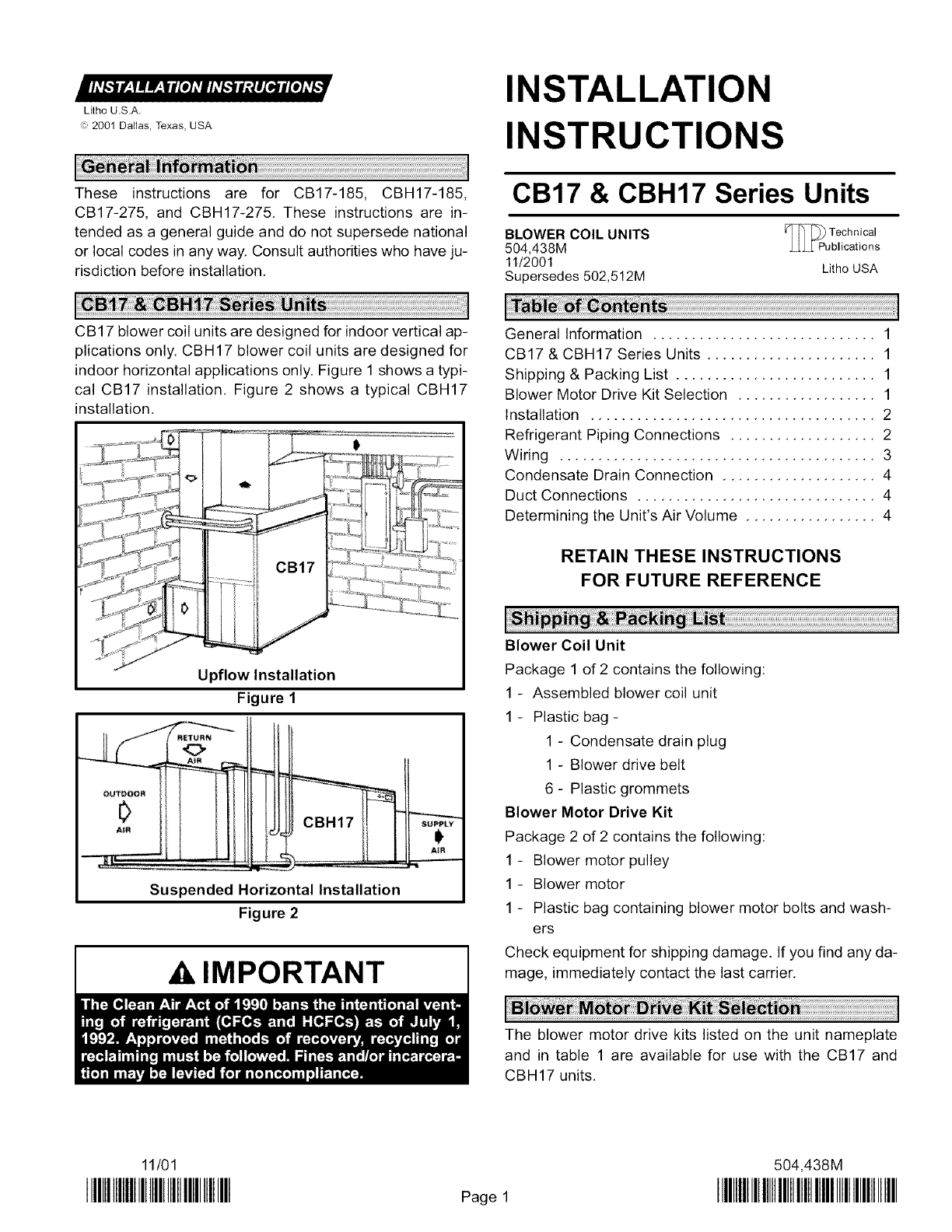
CB17 blower coil units are designed for indoor vertical ap-
plications only. CBH17 blower coil units are designed for
indoor horizontal applications only. Figure 1 shows a typi-
cal CB17 installation. Figure 2 shows a typical CBH17
installation.
CB17
Upflow Installation
Figure 1
OU_OOA
A_R
R_URN
<>
CBH17 su_v
Suspended Horizontal Installation
Figure 2
AIMPORTANT
General Information ............................. 1
CB17 & CBH17 Series Units ...................... 1
Shipping & Packing List .......................... 1
Blower Motor Drive Kit Selection .................. 1
Installation ..................................... 2
Refrigerant Piping Connections ................... 2
Wiring ......................................... 3
Condensate Drain Connection .................... 4
Duct Connections ............................... 4
Determining the Unit's Air Volume ................. 4
RETAIN THESE INSTRUCTIONS
FOR FUTURE REFERENCE
Blower Coil Unit
Package 1 of 2 contains the following:
1 - Assembled blower coil unit
1 - Plastic bag -
1 - Condensate drain plug
1 - Blower drive belt
6 - Plastic grommets
Blower Motor Drive Kit
Package 2 of 2 contains the following:
1 - Blower motor pulley
1 - Blower motor
1 - Plastic bag containing blower motor bolts and wash-
ers
Check equipment for shipping damage. If you find any da-
mage, immediately contact the last carrier,
The blower motor drive kits listed on the unit nameplate
and in table 1 are available for use with the CB17 and
CBH17 units.
11/01
IIIHIIIIIIIIIIIIIIIIIIIIIIIIIIIIIIIII Page 1
504,438M
IIIIIIIIIIIIIIIIIIIIIIIIIIIIIIIIIIIIIIIIIIIIIIIIII
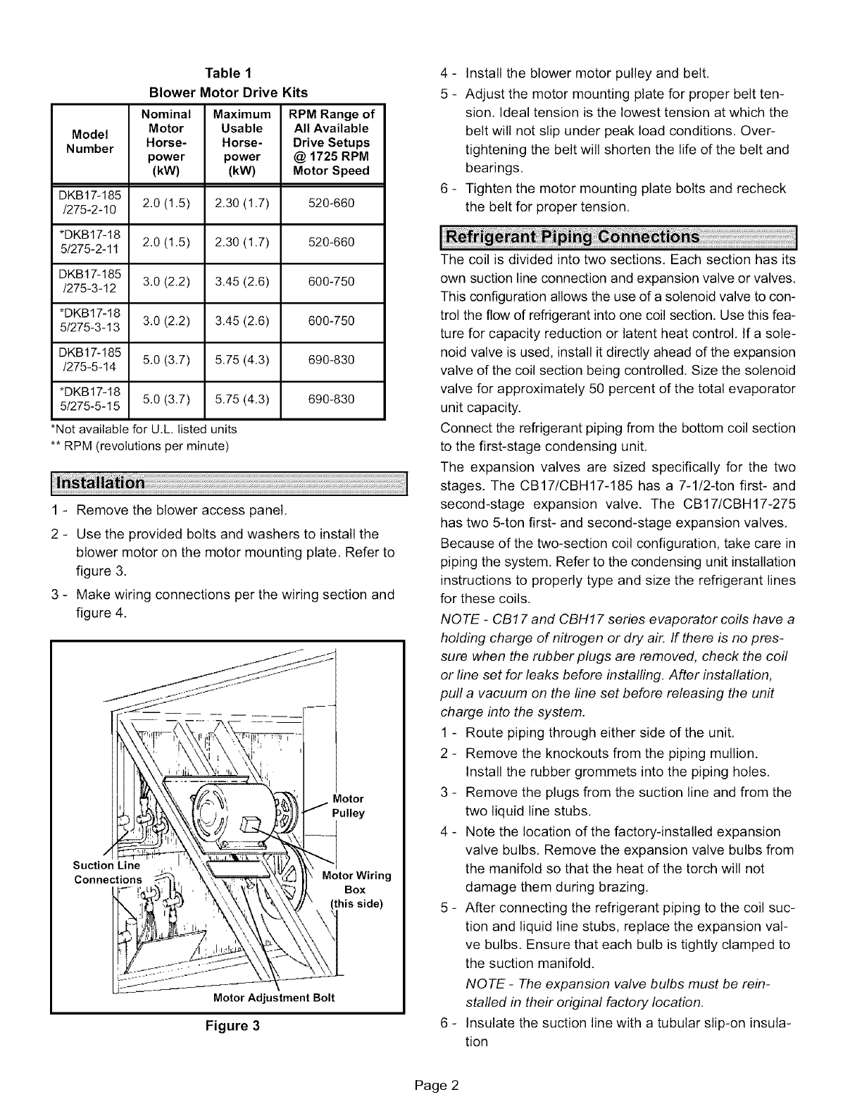
Table 1
Blower Motor Drive Kits
Nominal Maximum RPM Range of
Model Motor Usable All Available
Number Horse- Horse- Drive Setups
power power @ 1725 RPM
(kW) (kW) Motor Speed
DKB17-185
/275-2-10 2.0 (1.5) 2.30 (1.7) 520-660
*DKB17-18
5/275-2-11 2.0 (1.5) 2.30 (1.7) 520-660
DKB17-185
/275-3-12 3.0 (2.2) 3.45 (2.6) 600-750
*DKB17-18
5/275-3-13 3.0 (2.2) 3.45 (2.6) 600-750
DKB17-185
/275-5-14 5.0 (3.7) 5.75 (4.3) 690-830
*DKB17-18
5/275-5-15 5.0 (3.7) 5.75 (4.3) 690-830
*Not available for U.L. listed units
** RPM (revolutions per minute)
1 - Remove the blower access panel,
2 - Use the provided bolts and washers to install the
blower motor on the motor mounting plate. Refer to
figure 3,
3 - Make wiring connections per the wiring section and
figure 4.
Motor
Pulley
Suction Line
Connections Motor Wiring
Box
side)
Motor Adjustment Bolt
Figure 3
4 - Install the blower motor pulley and belt,
5 - Adjust the motor mounting plate for proper belt ten-
sion, Ideal tension is the lowest tension at which the
belt will not slip under peak load conditions. Over-
tightening the belt will shorten the life of the belt and
bearings,
6 - Tighten the motor mounting plate bolts and recheck
the belt for proper tension.
The coil is divided into two sections, Each section has its
own suction line connection and expansion valve or valves.
This configuration allows the use of a solenoid valve to con-
trol the flow of refrigerant into one coil section. Use this fea-
ture for capacity reduction or latent heat control, If a sole-
noid valve is used, install it directly ahead of the expansion
valve of the coil section being controlled. Size the solenoid
valve for approximately 50 percent of the total evaporator
unit capacity.
Connect the refrigerant piping from the bottom coil section
to the first-stage condensing unit.
The expansion valves are sized specifically for the two
stages. The CB17/CBH17-185 has a 7-1/2-ton first- and
second-stage expansion valve. The CB17/CBH17-275
has two 5-ton first- and second-stage expansion valves,
Because of the two-section coil configuration, take care in
piping the system, Refer to the condensing unit installation
instructions to properly type and size the refrigerant lines
for these coils.
NOTE -CBf 7 and CBHf 7 series evaporator coils have a
holding charge of nitrogen or dry air, If there is no pres-
sure when the rubber plugs are removed, check the coil
or line set for leaks before installing, After installation,
puff a vacuum on the line set before releasing the unit
charge into the system.
1 - Route piping through either side of the unit.
2 - Remove the knockouts from the piping mullion.
Install the rubber grommets into the piping holes,
3 - Remove the plugs from the suction line and from the
two liquid line stubs,
4 - Note the location of the factory-installed expansion
valve bulbs. Remove the expansion valve bulbs from
the manifold so that the heat of the torch will not
damage them during brazing.
5 - After connecting the refrigerant piping to the coil suc-
tion and liquid line stubs, replace the expansion val-
ve bulbs, Ensure that each bulb is tightly clamped to
the suction manifold.
NOTE -The expansion valve bulbs must be rein-
staffed in their original factory location,
6 - Insulate the suction line with a tubular slip-on insula-
tion
Page 2
NOTE -Complete all refrigerant piping connections be-
fore installing the blower contactor kit,
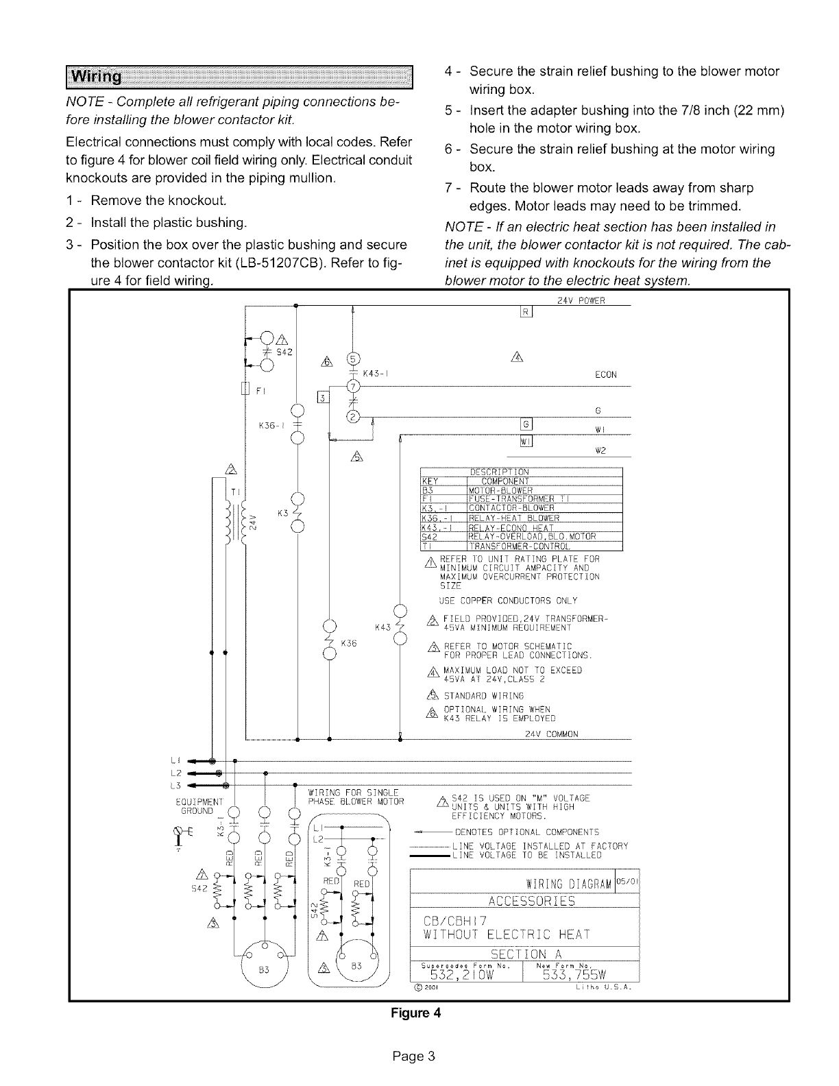
Electrical connections must comply with local codes. Refer
to figure 4 for blower coil field wiring only. Electrical conduit
knockouts are provided in the piping mullion,
1 - Remove the knockout,
_
_
4 - Secure the strain relief bushing to the blower motor
wiring box,
5 - Insert the adapter bushing into the 7/8 inch (22 mm)
hole in the motor wiring box,
6 - Secure the strain relief bushing at the motor wiring
box.
7 - Route the blower motor leads away from sharp
edges, Motor leads may need to be trimmed,
NOTE -If an electric heat section has been installed in
the unit, the blower contactor kit is not required. The cab-
inet is equipped with knockouts for the wiring from the
blower motor to the electric heat system.
Install the plastic bushing,
Position the box over the plastic bushing and secure
the blower contactor kit (LB-51207CB), Refer to fig-
ure 4 for field wiring,
- %JZ_
S4
K36 _
_> K3S
q
LI)U] MEN
GROUND _
T
A
A
K36
24V POWER
A
ECON
o
w2
DESCRIPTION
<EY COMPONENT
B3 MO]ORoBLOWER
:1 FUSE-1RANSFORMER ]1
<5, I CONTACTOR BLOWER
(56,-I RELAY HEAT BLOWER
(45,-I RELAY-ECONO HEAT
_42 REIAY-OVERLDAD,BLO,MOTOR
11 ]RANSFORMER_CONfROL
MAXIMUM OVERCURRENT PROTECTION
SIZE
USE COPPER CONDUCTORS ONLY
A FIELD PROVIDEB,24V TRANSFORMER-
45VA MINIMUM REOUIREMENT
_MAXIMUM LOAD NOT TO EXCEED
45VA AT 24V,CLASS 2
A STANDARD WIRINg
OPTIONAl WIRING WHEN
K43 RELAY IS EMPLOYED
24V COMMON
WIRING FOR SINGLE
PHASE: BLDWE:R MDTDR AS42 IS USED ON "M" VOLTAGE
LL_ UNITS & UNITS WITH HIGH
EFFICIENCY MOTORS.
_ _ / --LINE VOLTAGE TO BE INSTALLED
Ld U_ L_
ACCESSORIES
_" CB/CBH 7
A ......... WITHOUT ELECTRIC HEAT
SECTION A
Supersedes Form No, [ New Form No,
552,210W 555,755W
(_) 200_ L fho U.S.A.
Figure 4
Page 3
Theunitisequippedwithacondensatedrainoutletoneach
side.
1- Installtheprovideddrainpluginthecondensateout-
letthatwillnotbeused,
2- Installcondensatepipingusingproperlysizedfield-
providedfittings,
3- Installa trapinthedrainlinewherethedrainexits
theunit.
4- Pitchthedrainlinedownwardtotheopendrainor
sump,
NOTE -Never connect the condensate drain to a
closed system,
5 - Use plugged tees where possible to facilitate clean-
ing the drain lines.
If a return air plenum is not used. installation codes may
limit installation to single-story structures only.
Table 2
Do not install the supply air plenum within 18 inches (457
mm) of the blower access panel,
NOTE -Use flexible duct to eliminate vibration,
NOTE -The indoor coil must be dry and the air filters
must be in place when the following measurements are
taken,
1 - Run the blower without a cooling demand,
2 - Measure the static pressure external to the unit,
3 - Measure the indoor blower motor's rpm,
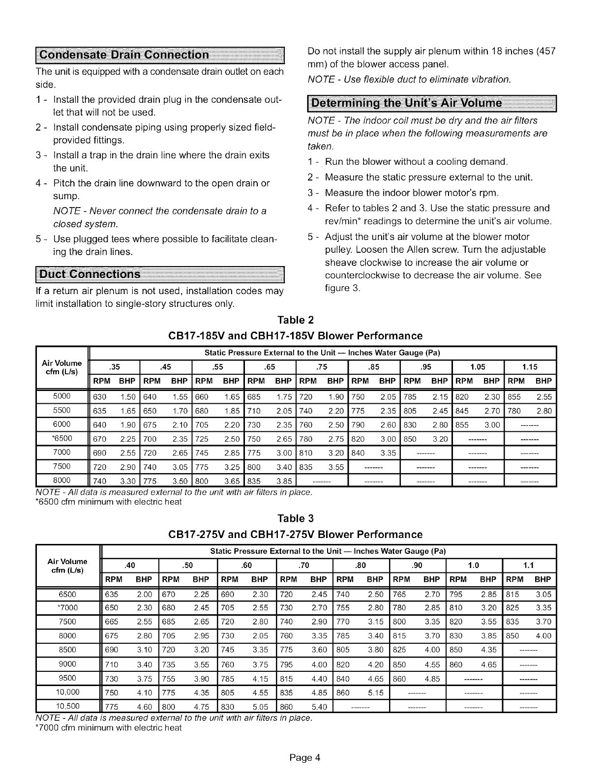
4 - Refer to tables 2 and 3, Use the static pressure and
rev/min* readings to determine the unit's air volume.
5 - Adjust the unit's air volume at the blower motor
pulley. Loosen the Allen screw, Turn the adjustable
sheave clockwise to increase the air volume or
counterclockwise to decrease the air volume. See
figure 3.
CB17-185V and CBH17-185V Blower Performance
Static Pressure External to the Unit -- Inches Water Gauge (Pa)
Air Volume .35 .45 .55 .65 .75 .85 .95 1.05 1.15
cfm (L/s) RPM BHP RPM BHP RPM BHP RPM BHP RPM BHP RPM BHP RPM BHP RPM BHP RPM BHP
5000 630 1.50 640 1.55 660 1.65 685 1.75 720 1.90 750 2.05 785 2.15 820 2.30 855 2.55
5500 635 1.65 650 1.70 680 1.85 710 2.05 740 2.20 775 2.35 805 2.45 845 2.70 780 2.80
6000 640 1.90 675 2.10 705 2.20 730 2.35 760 2.50 790 2.60 830 2.80 855 3.00 .......
*6500 670 2.25 700 2.35 725 2.50 750 2.65 780 2.75 820 3.00 850 3.20 ..............
7000 690 2.55 720 2.65 745 2.85 775 3.00 810 3.20 840 3.35 .....................
7500 720 2.90 740 3.05 775 3.25 800 3.40 835 3.55 ............................
8000 740 3.30 775 3.50 800 3.65 835 3.85 ...................................
NOTE -All data is measured external to the unit with air filters in place.
*6500 cfm minimum with electric heat
Table 3
CB17-275V and CBH17-275V Blower Performance
Static Pressure External to the Unit iInches Water Gauge (Pa)
Air Volume .60 .70 .80 .90 1.0 1.1
cfm (L/s) RPM BHP RPM BHP RPM BHP RPM BHP RPM BHP RPM BHP
2.25 690 2.30 720 2.45 740 2.50 765 2.70 795 2.85 815 3.05
2.45 705 2.55 730 2.70 755 2.80 780 2.85 810 3.20 825 3.35
2.65 720 2.80 740 2.90 770 3.15 800 3.35 820 3.55 835 3.70
2.95 730 2.05 760 3.35 785 3.40 815 3.70 830 3.85 850 4.00
3.20 745 3.35 775 3.60 805 3.80 825 4.00 850 4.35 .......
3.55 760 3.75 795 4.00 820 4.20 850 4.55 860 4.65 .......
3.90 785 4.15 815 4.40 840 4.65 860 4.85 ..............
4.35 805 4.55 835 4.85 860 5.15 .....................
4.75 830 5.05 860 5.40 ............................
unit with air filters in place.
.40 .50
RPM BHP RPM BHP
6500 635 2.00 670
*7000 650 2.30 680
7500 665 2.55 685
8000 675 2.80 705
8500 690 3.10 720
9000 710 3.40 735
9500 730 3.75 755
10,000 750 4.10 775
10,500 775 4.60 800
NOTE -All data is measured extemaltothe
*7000cfmminimumwith electric heat
Page 4
