LENNOX Air Conditioner/heat Pump(outside Unit) Manual L0805471
User Manual: LENNOX LENNOX Air conditioner/heat pump(outside unit) Manual LENNOX Air conditioner/heat pump(outside unit) Owner's Manual, LENNOX Air conditioner/heat pump(outside unit) installation guides
Open the PDF directly: View PDF ![]() .
.
Page Count: 2
LENNOX
1,_2003 Lennox Industries tnc,
Dallas, Texas, USA
COOLING KITS AND ACCESSORIES Fj_ppuTeCh n ical
blications
Lithe U.S.A.
504,724M
04/03
Supersedes 503,399M
CONDENSER COIL
REPLACEMENT KIT
INSTALLATION INSTRUCTIONS FOR REPLACEMENT CONDENSER
COIL FOR HS29 AND 10ACB SERIES UNITS
Package 1 of 1 contains:
1 - Condenser coil
1 - Discharge line
Check the replacement coil for shipping damage. If you
find any damage, immediately contact the last carrier.
8 -Replace top cap and control box. Restore power.
9-Refer to the unit installation instructions for leak
testing, evacuation and start-up procedures. Charge
the unit as outlined in the installation instructions or
charging sticker.
NOTE -Cut and debut the discharge manifold as
needed.
Use this kit for HS29-1, -2 and 10ACB-1, -2, -3, -4, -5, and
-6 series units. The kit is a direct replacement for HS29-2
and 10ACB-3, -4, -5, and -6 units. The enclosed plumbing
parts are not needed. To apply the kit to HS29-1 and 10
ACB-1 and -2 units, use the provided parts to slightly
modify the plumbing.
1 -Disconnect the power from the unit.
2 -Reclaim the refrigerant from the unit.
3 -Remove top cap and control box from the unit.
4 -HS29-1 and 10ACB-1, -2 Units - Sweat off the liquid
line from the service valve. Protect the valve with a
wet rag. Sweat off the discharge line from the
compressor at the discharge elbow. Discard the
removed plumbing parts.
HS29-2 and 10ACB-3, -4, -5, and -6 Units - Sweat
off the liquid line from the service valve. Protect the
valve with a wet rag, Sweat off discharge line at
manifold section of coil, Discard the removed
plumbing parts.
5 -Remove the condenser coil assembly from the unit,
6 -Install the replacement coil assembly.
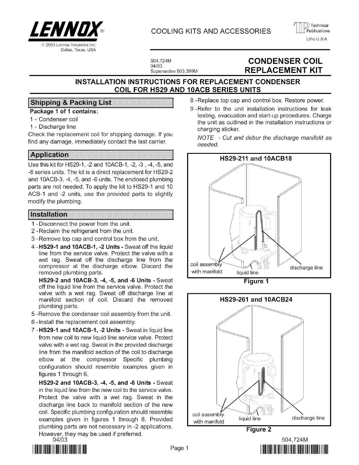
7 -HS29-1 and 10ACB-1, -2 Units - Sweat in liquid line
from new coil to new liquid line service valve, Protect
valve with a wet rag. Sweat in the provided discharge
line from the manifold section of the coil to discharge
elbow at the compressor Specific plumbing
configuration should resemble examples given in
figures 1 through 6,
HS29-2 and 10ACB-3, -4, -5, and -6 Units - Sweat
in the liquid line from the new coil to the service valve.
Protect the valve with a wet rag. Sweat in the
discharge line back to manifold section of the new
coil. Specific plumbing configuration should resemble
examples given in figures 1 through 6. Provided
plumbing parts are not necessary in -2 applications.
However, they may be used if preferred.
04/03
IIIHI£1111111111111111111Page1
HS29-211 and 10ACB18
coil assembly
with manifold discharge line
liquid line
Figure 1
H829-261 and 10ACB24
coil assembly
with manifold liquid line
Figure 2
discharge line
504,724M
IIIIIIIIIIIIllllllllllllllllllllllllllllllllllllll
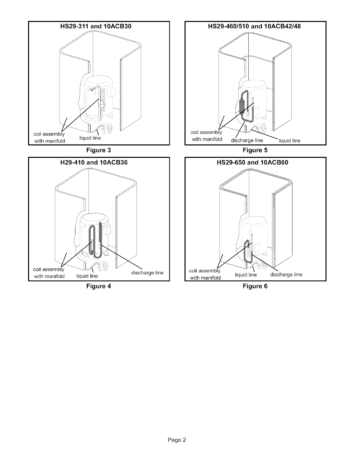
HS29-311 and 10ACB30
coil assembly
with manifold liquid line
Figure 3
H29-410 and 10ACB36
coil assembly
with manifold liquid line discharge line
Figure 4
HS29-460/510 and 10ACB42/48
coil assembly
with manifold discharge line liquid line
Figure 5
HS29-650 and 10ACB60
Y
with manifold liquid line discharge line
Figure 6
Page 2
