LENNOX Furnace/Heater, Gas Manual L0806201
User Manual: LENNOX LENNOX Furnace/Heater, Gas Manual LENNOX Furnace/Heater, Gas Owner's Manual, LENNOX Furnace/Heater, Gas installation guides
Open the PDF directly: View PDF ![]() .
.
Page Count: 50
_;_,2006 Lennox Industries Inc.
Dallas, Texas, USA
INSTALLATION
INSTRUCTIONS
G60UHV(X) Series
GAS FURNACE _-_") Technical
505,121M _--_.L_Publications
09/2006
Supersedes 06/2006 Lithe U.S.A.
RETAIN THESE INSTRUCTIONS
FOR FUTURE REFERENCE
Unit Dimensions ................................ 2
G60UHV(X) Parts Arrangement ................... 3
G60UHV(X) Gas Furnace ........................ 4
Shipping and Packing List ........................ 4
Safety Information ............................... 4
General ........................................ 5
Combustion, Dilution & Ventilation Air .............. 6
Setting Equipment ............................... 9
Filters .......................................... 13
Duct System .................................... 13
Venting ........................................ 13
Gas Piping ..................................... 21
Electrical ....................................... 22
Integrated Control Board Settings ................. 28
Unit Start-Up ................................... 37
Gas Pressure Adjustment ........................ 38
High Altitude Information ......................... 38
Other Unit Adjustments .......................... 38
Heating Sequence of Operation ................... 39
Service ........................................ 40
Repair Parts List ................................ 42
Ignition Control Board Diagnostic Codes ........... 43
Troubleshooting ................................. 44
Start-Up & Performance Check List ................ 50
AWARNING
Do not store or use gasoline or other
flammable vapors and liquids in the
vicinity of this or any other ap-
pliance.
Installation and service must be
performed by a qualified installer,
service agency or the gas supplier.
WHAT TO DO IF YOU SMELL GAS:
• Do not try to light any appliance.
•Do not touch any electrical switch; do not
use any phone in your building.
•Leave the building immediately.
•Immediately call your gas supplier from a
neighbor's phone. Follow the gas supplier's
instructions.
•If you cannot reach your gas supplier, call
the fire department.
09/06
iiiHiinlnlllllllllnllllllllllllllllll Page1
505,121M
IIIlllllllllllllllllllllllllllllllllllllllllll

*NOTE - 60C and 60D units that require air volumes
over 1800 cfm (850 L/s) must have one of the following:
1. Return air from single side with transition which will
accommodate 20 x 25 x 1 in. (508 x 635 x 25 mm)
cleanable air filter. (Required to maintain proper air
velocity.)
2. Return air from single side with optional RAB Return
Air Base.
3. Return air from bottom.
4. Return air from both sides.
5. Return air from bottom and one side.
Refer to Engineering Handbook for additional information.
**Flue outlet may be horizontal but furnace must be
vented vertically
_Optional external side return air filter kit cannot be used
with the optional RAB Return Air Base.
3/4 (19) -I_
<1-9/16 (14)
_OPTIONAL
EXTERNAL
SIDE RETURN
AIR FILTER KIT
(Either Side)
14-3/4
(375)
(406)
5/8 (16)
|/ 3/4(19)
*Bottom Return
Air Opening
FRONT VIEW
40
(1016)
3"3/4 (95)-I_1 F
D
FLUE OUTLET
(Top)
_OPTIONAL _---'---'--_----__--_. I
EXTERNAL _ _ 23-3/4 t603_
SIDE RETURN - II - • ,- uI
AIR FILTER KIT I_-._ 25 (635) =I
(Either Side) TOP VIEW
TOP VIEW
3-1/4 (83) Right --I 4
8-1/8 (206) Left |3-31, L
-_ (95)
=I_._
t
l \
14 (356) Right
13-1/4 (337) Left
4-7/8 (124) Right
2-1/4 (57) Left
28-1/2
(724)
n._ 19-7/16._
(494)
23-1/2
(597)
4-1/4 *Bottom Return
(108) Air Opening
SIDE VIEW
ABCD
Model No. in. mm in. mm in. mm in. mm
G6OUHV-36A-070 14-1/2 368 13-3/8 340 13 330 4-1/2 114
G6OUHV-36B-090 17-1/2 446 16-3/8 416 16 406 6 152
G6OUHV-6OC-O9O, 21 533 19-7/8 454 19-1/2 495 7-3/4 197
G6OUHV-60C-110
G6OUHV-6OD-135 24-1/2 622 23-3/8 546 23 584 9-1/2 241
9/16
'91-(14)
Page 2
Gasket
Flue
Transition
FlueBoxGasket
Flue
Collector
Box
Combustion Air
Orifice
Combustion Air
Pressure Switch Assembly
(two switches)
./ Combustion Air Inducer
Flame Sensor Limit Shield
_Flame Rollout Switches \
Air Intake _ _ Primary \/I
Cover _ Limit
Burner //__ I
Box Tol I Kz'2 I
NOx Insert
Gas Valve
Gas
Orifices Gasket
Heat Exchanger
Sight
Glass
Burner
Box Cover
Bracket
Burner Box Bottom
Control Transformer
Ignitor
Circuit Breaker
Air Deflector
G60UH-60C-110
Units Only
\
Secondary Limit(s)
Power Choke
(1 hp Only)
Variable Speed
Blower Motor
Two-Stage, Variable Speed
Integrated Control Board
Door Interlock Switch
FIGURE 1
Page 3
TheG60UHV(X)gasfurnaceis equippedwitha two-
stage,variablespeedintegratedcontrol.Thiscontrolen-
surescompatibilitywithLennox'HarmonyIllzonecontrol
system,aswellasathermostatwhichprovideshumidity
control.EachG60UHV(X)unitisshippedreadyforinstal-
lationintheupfloworhorizontalposition(leftorright).The
furnaceisshippedwiththebottompanelinplace.Thebot-
tompanelmustberemovediftheunitistobeinstalledina
horizontalapplication.Thepanelmayalsoberemovedin
upflowapplications.
Package1of 1contains
1- AssembledG60UHV(X)unit
1- Bagassemblycontainingthefollowing:
2-Screws
3-Wirenuts
1-Snapbushing
1-Snapplug
1- Wiretie
1-Vent warning label
1 -Owner's manual and warranty card
The following items may be ordered separately:
1- Thermostat
1 - Hanging bracket (for horizontal installations)
1 - Propane/LP changeover kit
1 - Return air base
1 - High altitude kit
1 - Side filter kit
Check equipment for shipping damage. If you find any
damage, immediately contact the last carrier.
,&WARNING
,&,CAUTION
G60UHV(X) units are CSA International certified to ANSI
Z21.47 and CSA 2.3 standard.
In the USA, installation of gas furnaces must conform with
local building codes. In the absence of local codes, units
must be installed according to the current National Fuel
Gas Code (ANSI-Z223.1). The National Fuel Gas Code is
available from the following address:
American National Standards Institute, Inc.
11 West 42nd Street
New York, NY 10036
In Canada, installation must conform with current National
Standard of Canada CSA-B149 installation codes for natu-
ral gas and propane gas burning appliances and equip-
ment, local plumbing or waste water codes and other appli-
cable local codes.
Adequate clearance must be made around the air open-
ings into the vestibule area. In order to ensure proper unit
operation, combustion and ventilation air supply must be
provided according to the current National Fuel Gas Code
or CSA-B149 standards.
Vent installations must be consistent with the venting
tables (in this instruction) and applicable provisions of local
building codes.
This furnace is CSA Intemational certified for installation
clearances to combustible material as listed on the unit
nameplate and in the tables in figures 6 and 11.Accessibility
and service clearances must take precedence over fire
protection clearances.
NOTE- For installation on combustible floors, the furnace
shall not be installed directly on carpeting, tile, or other
combustible material other than wood flooring.
For installation in a residential garage, the furnace must
be installed so that the burner(s) and the ignition source
are located no less than 18 inches (457 mm) above the
floor. The furnace must be located or protected to avoid
physical damage by vehicles. When a furnace is installed
in a public garage, hangar, or other building that has a haz-
ardous atmosphere, the furnace must be installed accord-
ing to recommended good practice requirements and cur-
rent National Fuel Gas Code or CSA B149 standards.
NOTE -Furnace must be adjusted to obtain a temperature
rise(high and bw fire) within the range(s) specified on the unit
nameplate. Failure to do so may cause erratic limit operation.
This G60UHV(X) furnace must be installed so that its elec-
trical components are protected from water.
When this furnace is used with cooling units, it shall be
installed in parallel with, or on the upstream side of, cooling
units to avoid condensation in the heating compartment.
With a parallel flow arrangement, a damper (or other
means to control the flow of air) must adequately prevent
chilled air from entering the furnace. If the damper is manu-
ally operated, it must be equipped to prevent operation of
either the heating or the cooling unit, unless it is in the full
HEAT or COOL setting.
Page 4
Wheninstalled,thisfurnacemustbeelectricallygrounded
accordingtolocalcodes.Inaddition,intheUnitedStates,
installationmustconformwiththecurrentNationalElec-
tricCode,ANSI/NFPANo.70.TheNationalElectricCode
(ANSI/NFPANo.70)isavailablefromthefollowingad-
dress:
NationalFireProtectionAssociation
1BatteryMarchPark
Quincy,MA02269
InCanada,allelectricalwiringandgroundingfortheunit
mustbeinstalledaccordingtothecurrentregulationsofthe
CanadianElectricalCodePartI (CSAStandardC22.1)
and/orlocalcodes.
NOTE -This furnace is designed for a minimum continu-
ous return air temperature of 60°F (16°C) or an intermit-
tent operation down to 55°F (13°C) dry bulb for cases
where a night setback thermostat is used. Return air tem-
perature must not exceed 85°F (29 °C) dry bulb.
The G60UHV(X) furnace may be installed in alcoves, clos-
ets, attics, basements, garages, and utility rooms in the up-
flow or horizontal position.
This furnace design has not been CSA International certi-
fied for installation in mobile homes, recreational vehicles,
or outdoors.
Lennox does not recommend the use of G60UHV(X) units
as a construction heater during any phase of construction.
Very low return air temperatures, harmful vapors and op-
eration of the unit with clogged or misplaced filters will dam-
age the unit.
G60UHV(X) units may be used for heating of buildings or
structures under construction, if the following conditions
are met:
•The vent system must be permanently installed per
these installation instructions.
• A room thermostat must control the furnace. The use of
fixed jumpers that will provide continuous heating is not
aflowed.
• The return air duct must be provided and sealed to the
furnace.
• Return air temperature range between 60°F (16°C) and
80°F (27°C) must be maintained.
• Air filters must be instafled in the system and must be
maintained during construction.
• Air filters must be replaced upon construction comple-
tion.
• The input rate and temperature rise must be set per the
furnace rating plate.
•One hundred percent (100%) outdoor air must be pro-
vided for combustion air requirements during construc-
tion. Temporary ducting may supply outdoor air to the
furnace. Do not connect duct directly to the furnace.
Size the temporary duct following these instructions in
section for Combustion, Dilution and Ventilation Air in a
confined space with air from outside.
• The furnace heat exchanger, components, duct system,
air filters and evaporator coils must be thoroughly
cleaned following final construction clean-up.
• All furnace operating conditions (including ignition, in-
put rate, temperature rise and venting) must be verified
according to these installation instructions.
NOTE -The Commonwealth of Massachusetts stipu-
lates these additional requirements:
• Gas furnaces shall be installed by a llcensedplumb-
er or gas fittter only.
• The gas cock must be "T handle" type.
• When afurnace is installed in an attic, the passage-
way to and service area surrounding the equipment
shall be floored.
These instructions are intended as a general guide and do
not supersede local codes in any way. Consult authorities
having jurisdiction before installation.
In addition to the requirements outlined previously, the fol-
lowing general recommendations must be considered
when installing a G60UHV(X) furnace:
•Place the furnace as close to the center of the air dis-
tribution system as possible. The furnace should also be
located close to the chimney or vent termination point.
•Do not install the furnace where drafts might blow direct-
ly into it. This could cause improper combustion and un-
safe operation.
•Do not block the furnace combustion air openings with
clothing, boxes, doors, etc. Air is needed for proper
combustion and safe unit operation.
•When the furnace is installed in an attic or other insu-
lated space, keep insulation away from the furnace.
Page 5
j WARNING ACAUTION
In the past, there was no problem in bringing in sufficient out-
door air for combustion. Infiltration provided all the air that
was needed. In today's homes, tight construction practices
make it necessary to bring in air from outside for combus-
tion. Take into account that exhaust fans, appliance vents,
chimneys, and fireplaces force additional air that could be
used for combustion out of the house. Unless outside air is
brought into the house for combustion, negative pressure
(outside pressure is greater than inside pressure) will build
to the point that a downdraft can occur in the furnace vent
pipe or chimney. As a result, combustion gases enter the liv-
ing space creating a potentially dangerous situation.
In the absence of local codes concerning air for combus-
tion and ventilation, use the guidelines and procedures in
this section to install G60UHV(X) furnaces to ensure effi-
cient and safe operation. You must consider combustion air
needs and requirements for exhaust vents and gas piping.
A portion of this information has been reprinted with per-
mission from the National Fuel Gas Code (ANSI-Z223.1).
This reprinted material is not the complete and official posi-
tion of the ANSI on the referenced subject, which is repre-
sented only by the standard in its entirety.
In Canada, refer to the standard CSA B149 installation
codes.
&CAUTION
All gas-fired appliances require air for the combustion pro-
cess. If sufficient combustion air is not available, the fur-
nace or other appliances will operate inefficiently and un-
safely, Enough air must be provided to meet the needs of all
fuel-burning appliances and appliances such as exhaust
fans which force air out of the house, When fireplaces, ex-
haust fans, or clothes dryers are used at the same time as
the furnace, much more air is necessary to ensure proper
combustion and to prevent a downdraft. Insufficient air
causes incomplete combustion which can result in carbon
monoxide,
In addition to providing combustion air, fresh outdoor air
dilutes contaminants in the indoor air. These contami-
nants may include bleaches, adhesives, detergents, sol-
vents and other contaminants which can corrode furnace
components,
The requirements for providing air for combustion and ven-
tilation depend largely on whether the furnace is installed in
an unconfined or a confined space,
Unconfined Space
An unconfined space is an area such as a basement or
large equipment room with a volume greater than 50 cubic
feet (1,42 m3) per 1,000 Btu (.29 kW) per hour of the com-
bined input rating of all appliances installed in that space,
This space also includes adjacent rooms which are not
separated by a door. Though an area may appear to be un-
confined, it might be necessary to bring in outdoor air for
combustion if the structure does not provide enough air by
Page 6
infiltration,If thefurnaceis locatedin a buildingof tight
constructionwithweatherstrippingandcaulkingaround
thewindowsanddoors,followtheproceduresintheair
fromoutsidesection,
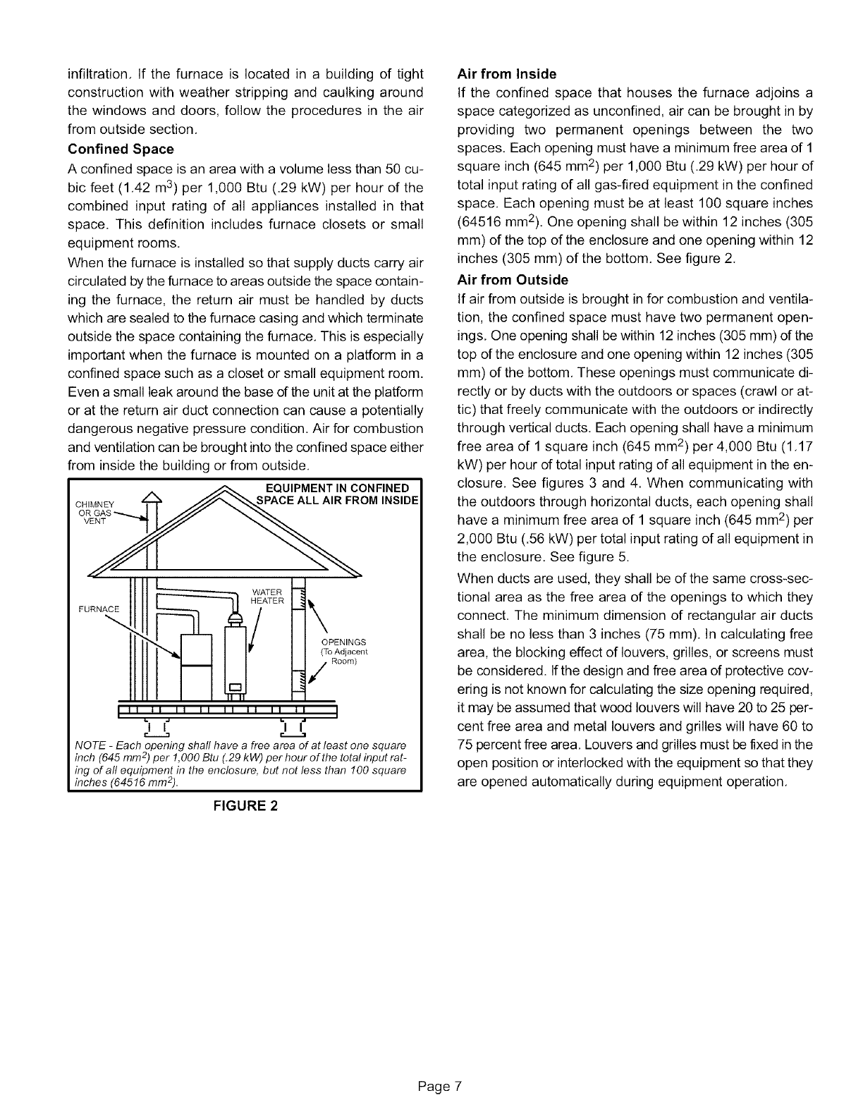
Confined Space
A confined space is an area with a volume less than 50 cu-
bic feet (1,42 m3) per 1,000 Btu (.29 kW) per hour of the
combined input rating of all appliances installed in that
space. This definition includes furnace closets or small
equipment rooms,
When the furnace is installed so that supply ducts carry air
circulated by the furnace to areas outside the space contain-
ing the furnace, the return air must be handled by ducts
which are sealed to the furnace casing and which terminate
outside the space containing the furnace, This is especially
important when the furnace is mounted on a platform in a
confined space such as a closet or small equipment room.
Even a small leak around the base of the unit at the platform
or at the return air duct connection can cause a potentially
dangerous negative pressure condition, Air for combustion
and ventilation can be brought into the confined space either
from inside the building or from outside.
__EQUIPMENT IN CONFINED
CHIMNEY _ /_ SPACE ALL AIR FROM INSIDE
OR GAS
h
_ WiTER /
HEATER
FURNACE 1_
OPENINGS
(To Adjacent
Room)
,,,,j, ,, ,, ,, ,, ,,,: ,,
I I I I
NOTE -Each opening shall have afree area of at least one square
inch (645 mm 2) per 1,000 Btu (.29 kW) per hour of the total input rat-
ing of all equipment in the enclosure, but not less than 100 square
inches (64516 ram2).
FIGURE 2
Air from Inside
If the confined space that houses the furnace adjoins a
space categorized as unconfined, air can be brought in by
providing two permanent openings between the two
spaces. Each opening must have a minimum free area of 1
square inch (645 mm2) per 1,000 Btu (.29 kW) per hour of
total input rating of all gas-fired equipment in the confined
space. Each opening must be at least 100 square inches
(64516 mm2). One opening shall be within 12 inches (305
mm) of the top of the enclosure and one opening within 12
inches (305 mm) of the bottom. See figure 2.
Air from Outside
If air from outside is brought in for combustion and ventila-
tion, the confined space must have two permanent open-
ings. One opening shall be within 12 inches (305 mm) of the
top of the enclosure and one opening within 12 inches (305
mm) of the bottom. These openings must communicate di-
rectly or by ducts with the outdoors or spaces (crawl or at-
tic) that freely communicate with the outdoors or indirectly
through vertical ducts. Each opening shall have a minimum
free area of 1 square inch (645 mm2) per 4,000 Btu (1,17
kW) per hour dtotal input rating of all equipment in the en-
closure, See figures 3 and 4. When communicating with
the outdoors through horizontal ducts, each opening shall
have a minimum free area of 1 square inch (645 mm 2) per
2,000 Btu (.56 kW) per total input rating of all equipment in
the enclosure, See figure 5.
When ducts are used, they shall be of the same cross-sec-
tional area as the free area of the openings to which they
connect. The minimum dimension of rectangular air ducts
shall be no less than 3 inches (75 mm). In calculating free
area, the blocking effect of louvers, grilles, or screens must
be considered. Ifthe design and free area of protective cov-
ering is not known for calculating the size opening required,
it may be assumed that wood louvers will have 20 to 25 per-
cent free area and metal louvers and grilles will have 60 to
75 percent free area. Louvers and grilles must be fixed in the
open position or interlocked with the equipment so that they
are opened automatically during equipment operation.
Page 7
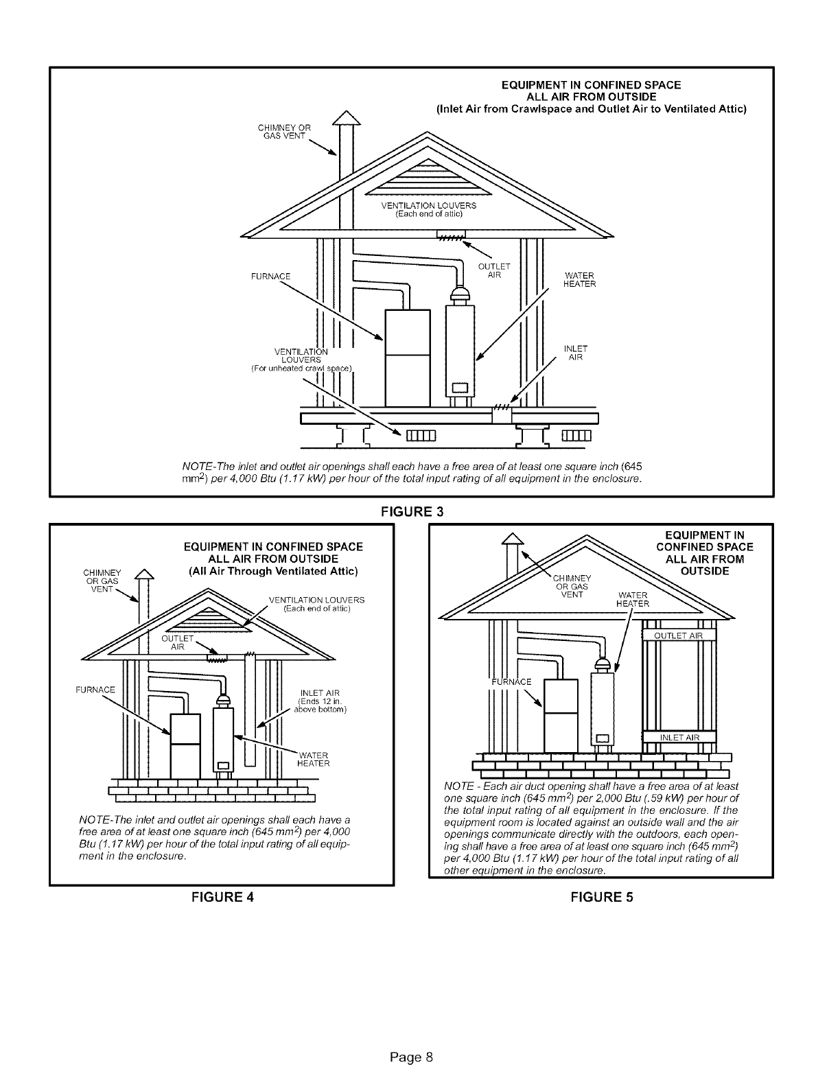
CHIMNEY OR
GAS VENT
EQUIPMENT IN CONFINED SPACE
ALL AIR FROM OUTSIDE
(Inlet Air from Crawlspace and Outlet Air to Ventilated Attic)
VENTILATION LOUVERS
(Each end of altic)
I ...... I
OUTLET
FURNACE AIR WATER
HEATER
VENTILATION INLET
LOUVERS AIR
(For unheated crawl ._
_1 _rrrm rrrm I
NOTE-The inlet and outlet air openings shall each have a free area of at least one square inch (645
mm2) per 4, 000 Btu (1.17 kW) per hour of the total input rating of all equipment in the enclosure.
CHIMNEY
OR GAS
VENT'_
EQUIPMENT IN CONFINED SPACE
ALL AIR FROM OUTSIDE
(All Air Through Ventilated Attic)
VENTILATION LOUVERS
(Each end of attic)
FURNACE INLET AIR
Ends 12 in.
above bottom
HEATER
NO TE-The inlet and outlet air openings shaft each have a
free area of at least one square inch (645 mm 2)per 4,000
Btu (1.17 kW) per hour of the total input rating of aft equip-
ment in the enclosure.
FIGURE 4
FIGURE 3
A _ EQUIPMENT IN
TT_. JJ_ CONFINED SPACE
I I "b__JY _ ALLAIRFROM
!lq!ll
NLET AI
II II l . . 1T-T. II II II IL_
I I I I I I I I I I I___J
IIIIIIII II I
I I I I I I I I I I I I
NOTE -Each air duct opening shaft have a free area of at least
one square inch (645 mm 2)per 2,000 Btu (.59 kW) per hour of
the total input rating of aft equipment in the enclosure. If the
equipment room is located against an outside wall and the air
openings communicate directly with the outdoors, each open-
ing shaft have a free area of at least one square inch (645 mm 2)
per 4,000 Btu (1.17 kW) per hour of the total input rating of aft
other equipment in the enclosure.
FIGURE 5
Page 8
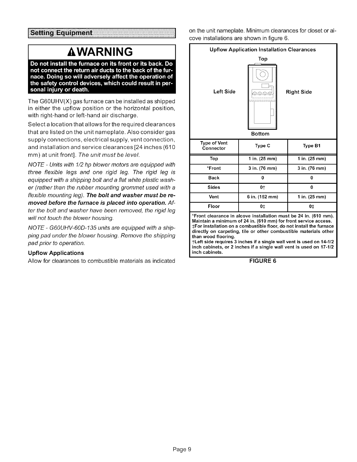
-&WARNING
The G60UHV(X) gas furnace can be installed as shipped
in either the upflow position or the horizontal position,
with right-hand or left-hand air discharge.
Select a location that allows for the required clearances
that are listed on the unit nameplate. Also consider gas
supply connections, electrical supply, vent connection,
and installation and service clearances [24 inches (610
mm) at unit front]. The unit must be level.
NOTE -Units with 1/2 hp blower motors are equipped with
three flexible legs and one rigid leg. The rigid leg is
equipped with a shipping bolt and a flat white plastic wash-
er (rather than the rubber mounting grommet used with a
flexible mounting leg). The bolt and washer must be re-
moved before the furnace is placed into operation. Af-
ter the bolt and washer have been removed, the rigid leg
will not touch the blower housing.
NOTE -G60UHV-60D-135 units are equipped with a ship-
ping pad under the blower housing. Remove the shipping
pad prior to operation.
Upflow Applications
Allow for clearances to combustible materials as indicated
on the unit nameplate, Minimum clearances for closet or al-
cove installations are shown in figure 6.
Upflow Application Installation Clearances
Top
Left Side
Bottom
Right Side
Type of Vent Type C Type B1
Connector
Top 1 in. (25 ram) 1 in. (25 ram)
*Front 3 in. (76 ram) 3 in. (76 ram)
Back 0 0
Sides 01- 0
Vent 6 in. (152 ram) 1 in. (25 ram)
Floor 05 05
*Front clearance in alcove installation must be 24 in. (610 ram).
Maintain a minimum of 24 in. (610 ram) for front service access.
SFor installation on a combustible floor, do not install the furnace
directly on carpeting, tile or other combustible materials other
than wood flooring.
1-Left side requires 3 inches if a single wall vent is used on 14-1/2
inch cabinets, or 2 inches if a single wall vent is used on 17-1/2
inch cabinets.
FIGURE 6
Page 9
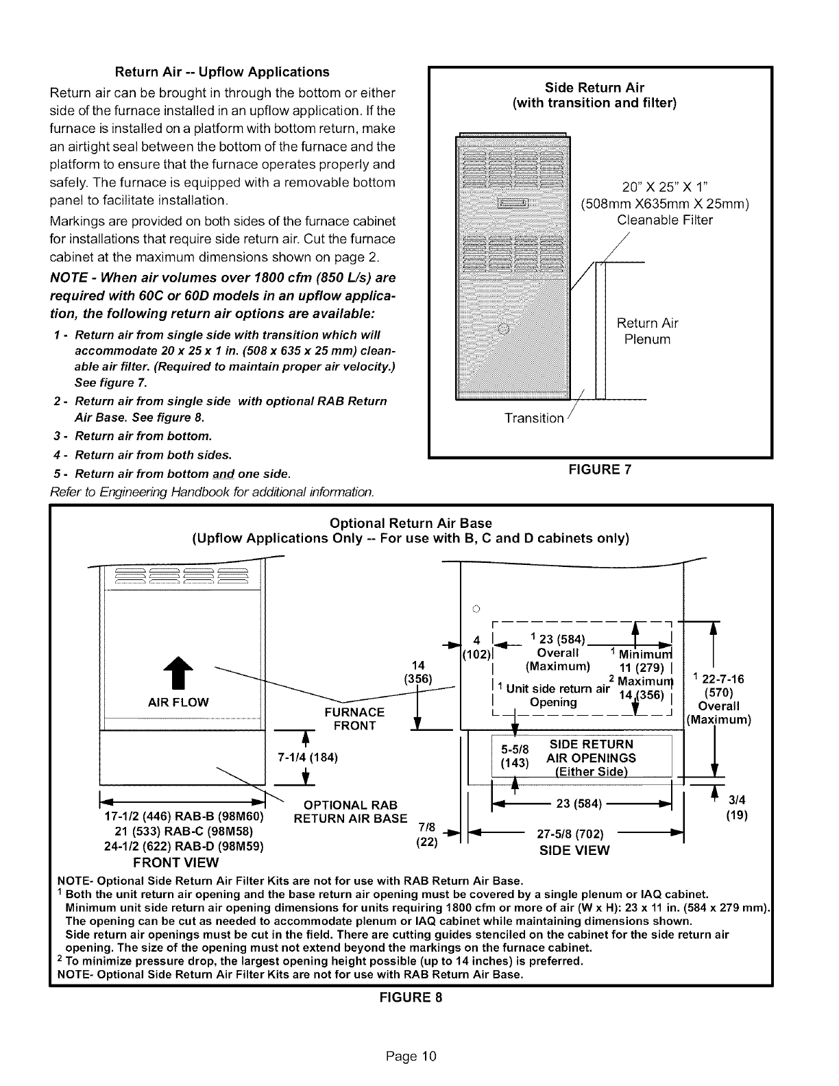
Return Air -- Upflow Applications
Return air can be brought in through the bottom or either
side of the furnace installed in an upflow application, If the
furnace is installed on a platform with bottom return, make
an airtight seal between the bottom of the furnace and the
platform to ensure that the furnace operates properly and
safely. The furnace is equipped with a removable bottom
panel to facilitate installation,
Markings are provided on both sides of the furnace cabinet
for installations that require side return air. Cut the furnace
cabinet at the maximum dimensions shown on page 2.
NOTE -When air volumes over 1800 cfm (850 L/s) are
required with 60C or 60D models in an upflow applica-
tion, the following return air options are available:
1-Return air from single side with transition which will
accommodate 20 x 25 x I in. (508 x 635 x 25 ram) clean-
able air filter. (Required to maintain proper air velocity.)
See figure 7.
2-Return air from single side with optional RAB Return
Air Base. See figure 8.
3-Return air from bottom.
4-Return air from both sides.
5-Return air from bottom and one side.
Refer to Engineering Handbook for additional information,
Side Return Air
(with transition and filter)
20" X 25" X 1"
(508mm X635mm X 25mm)
Cleanable Filter
_/
Return Air
Plenum
FIGURE 7
Optional Return Air Base
(Upflow Applications Only -- For use with B, Cand D cabinets only)
J
t
AIR FLOW
14 "-_
L
7-1/4 (184)
vI
17-1/2 (446) RAB-B (98M60)
21 (533) RAB-C (98M58)
24-1/2 (622) RAB-D (98M59)
FRONT VIEW
OPTIONAL RAB
RETURN AIR BASE 7/8 .._
(22)
©
m 7
4;-.91-- 1 23 (584) f =1
102)1 Overall 1Minimum
(Maximum) 11 (279) I
2 Maximun_
1Unit side return air 1A 1356)_
Opening ___jl__ _
I
5-5/8 SIDE RETURN
(143) AIR OPENINGS
(Either Side)
_1_ 23 (584)
I
I
122-7-16
(570)
Overall
'Maximum)
_J_
._ _ 3/4
(19)
91--- 27-5/8 (702)
SIDE VIEW
NOTE- Optional Side Return Air Filter Kits are not for use with RAB Return Air Base.
1 Both the unit return air opening and the base return air opening must be covered by a single plenum or IAQ cabinet.
Minimum unit side return air opening dimensions for units requiring 1800 cfm or more of air (W x H): 23 x 11 in. (584 x 279 mm).
The opening can be cut as needed to accommodate plenum or IAQ cabinet while maintaining dimensions shown.
Side return air openings must be cut in the field. There are cutting guides stenciled on the cabinet for the side return air
opening. The size of the opening must not extend beyond the markings on the furnace cabinet.
2 To minimize pressure drop, the largest opening height possible (up to 14 inches) is preferred.
NOTE- Optional Side Return Air Filter Kits are not for use with RAB Return Air Base.
FIGURE 8
Page 10
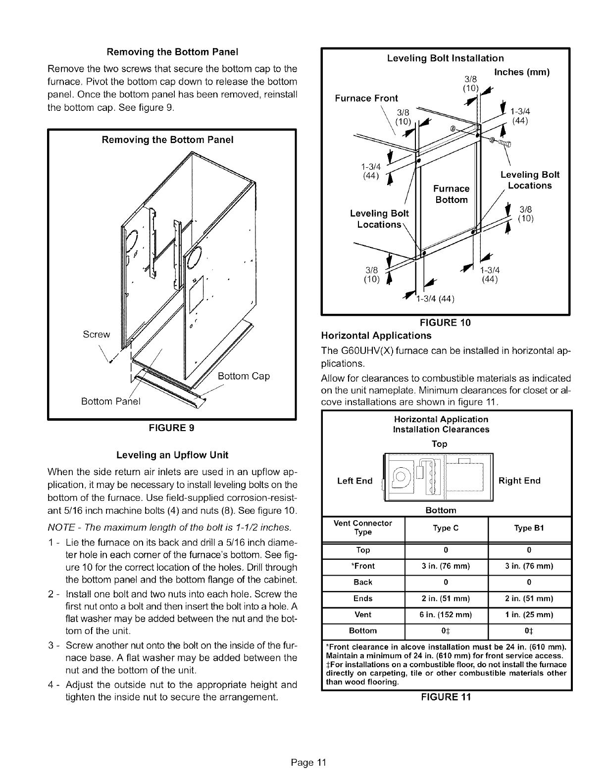
Removingthe Bottom Panel
Remove the two screws that secure the bottom cap to the
furnace. Pivot the bottom cap down to release the bottom
panel, Once the bottom panel has been removed, reinstall
the bottom cap. See figure 9,
Removing the Bottom Panel
Screw
\/
Bottom Cap
Bottom
FIGURE 9
Leveling an Upflow Unit
When the side return air inlets are used in an upflow ap-
plication, it may be necessary to install leveling bolts on the
bottom of the furnace. Use field-supplied corrosion-resist-
ant 5/16 inch machine bolts (4) and nuts (8), See figure 10,
NOTE -The maximum length of the bolt is 1-1/2 inches.
1 - Lie the furnace on its back and drill a 5/16 inch diame-
ter hole in each corner of the furnace's bottom, See fig-
ure 10 for the correct location of the holes, Drill through
the bottom panel and the bottom flange of the cabinet.
2 - Install one bolt and two nuts into each hole. Screw the
first nut onto a bolt and then insert the bolt into a hole. A
fiat washer may be added between the nut and the bot-
tom of the unit.
3 - Screw another nut onto the bolt on the inside of the fur-
nace base. A fiat washer may be added between the
nut and the bottom of the unit,
4 - Adjust the outside nut to the appropriate height and
tighten the inside nut to secure the arrangement,
Leveling Bolt Installation
Inches (mm)
3/8
(10)
Furnace Front
3/8 1-3/4
(44)
1-3/4
(44) Leveling Bolt
Locations
Leveling Bolt (3/8)
3/8 1-3/4
(10) (44)
1-3t4 (44)
FIGURE 10
Horizontal Applications
The G60UHV(X) furnace can be installed in horizontal ap-
plications,
Allow for clearances to combustible materials as indicated
on the unit nameplate. Minimum clearances for closet or al-
cove installations are shown in figure 11,
Horizontal Application
Installation Clearances
Top
Left End Right End
Vent Connector
Type
Top
*Front
Back
Ends
Vent
Bottom
Bottom
Type C
0
3in. (76 ram)
0
2 in. (51 ram)
6in. (152 ram)
05
Type B1
0
3in, (76 ram)
0
2 in. (51 ram)
1in. (25 ram)
05
*Front clearance in alcove installation must be 24 in. (610 ram).
Maintain a minimum of 24 in. (610 ram) for front service access.
SFor installations on a combustible floor, do not install the furnace
directly on carpeting, tile or other combustible materials other
than wood flooring.
FIGURE 11
Page 11
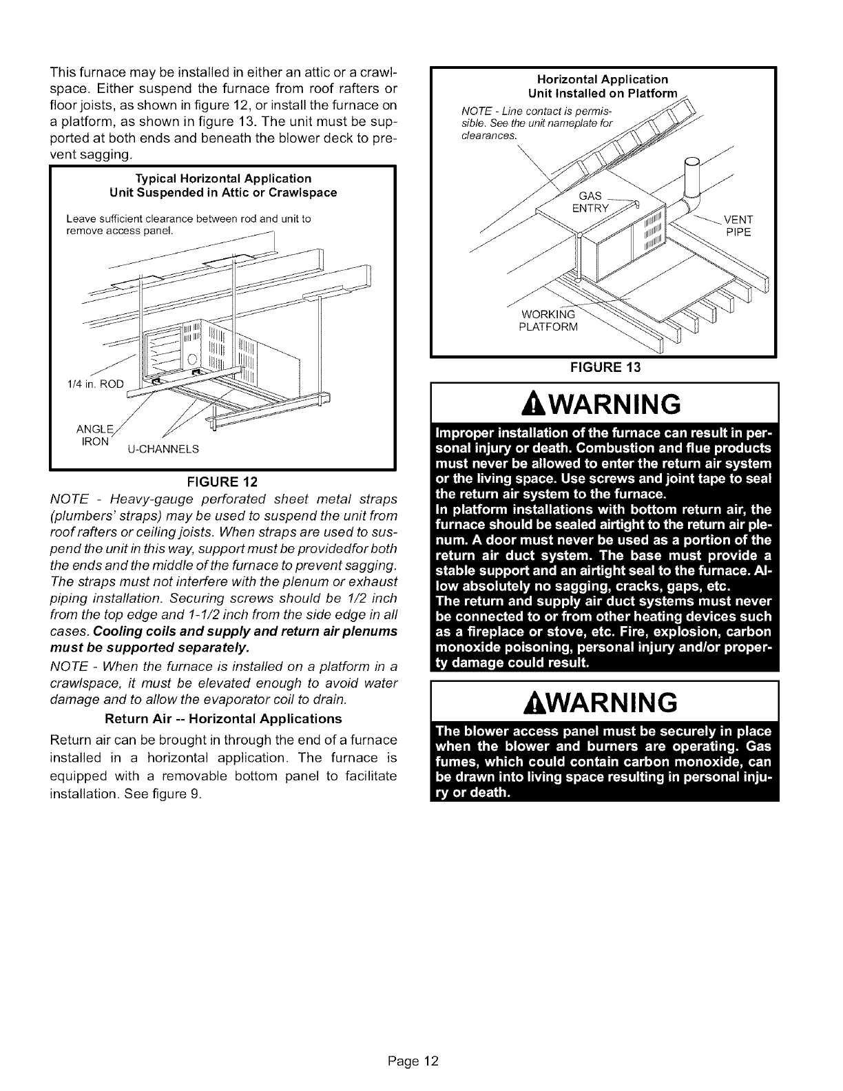
Thisfurnacemaybeinstalledineitheranatticoracrawl-
space.Eithersuspendthefurnacefromroofraftersor
floorjoists,asshowninfigure12,orinstallthefurnaceon
aplatform,asshownin figure13.Theunitmustbesup-
portedat bothendsandbeneaththeblowerdecktopre-
ventsagging.
Typical Horizontal Application
Unit Suspended in Attic or Crawlspace
Leave sufficient clearance between rod and unit to
remove access panel.
FIGURE 12
NOTE -Heavy-gauge perforated sheet metal straps
(plumbers' straps) may be used to suspend the unit from
roof rafters or ceiling joists. When straps are used to sus-
pend the unit in this way, support must be providedfor both
the ends and the middle of the furnace to prevent sagging.
The straps must not interfere with the plenum or exhaust
piping installation. Securing screws should be 1/2 inch
from the top edge and 1-1/2 inch from the side edge in all
cases. Cooling coils and supply and return air plenums
must be supported separately.
NOTE -When the furnace is installed on a platform in a
crawlspace, it must be elevated enough to avoid water
damage and to allow the evaporator coil to drain.
Return Air -- Horizontal Applications
Return air can be brought in through the end of a furnace
installed in a horizontal application. The furnace is
equipped with a removable bottom panel to facilitate
installation. See figure 9.
Horizontal Application
Unit Installed on Platform
NOTE -Line contact is permis-
sible. See the unit nameplate for
clearances.
\\\"x,
FIGURE 13
WARNING
_&WARNING
Page 12
Thisunitisnotequippedwitha filteror rack.A field-pro-
videdhigh-velocityfilterisrequiredfortheunittooperate
properly,Table1listsrecommendedfiltersizes,
A filtermustbein placeanytimetheunitisoperating,
TABLE1
Furnace
Cabinet Size
14-1/2"
17-1/2"
21"
24-1/2"
Filter Size
Side Return
16X25X1 (1)
16X25X1 (1)
16X25X1 (1)
16X25X1 (2)
Bottom Return
14X25X 1 (1)
16X25X 1 (1)
20 X 25 X 1 (1)
24 X 25 X 1 (1)
Use industry-approved standards (such as those pub-
lished by Air Conditioning Contractors of America or Ameri-
can Society of Heating, Refrigerating and Air Conditioning
Engineers) to size and install the supply and return air duct
system. This will result in a quiet and low-static system that
has uniform air distribution.
NOTE -Do not operate the furnace with an external static
pressure that exceeds 0.8 inches w.c. Higher external stat-
ic pressures may cause erratic tim# operation.
Supply Air Plenum
If the furnace is installed without a cooling coil, a removable
access panel must be installed in the supply air duct. The
access panel should be large enough to permit inspection
(either by smoke or reflected light) of the heat exchanger
for leaks after the furnace is installed. The furnace access
panel must always be in place when the furnace is operat-
ing and it must not allow leaks into the supply air duct sys-
tem.
Return Air Plenum
Return air must not be drawn from a room where this
furnace, or any other gas appliance (ie., a water heat-
er), is installed. When return air is drawn from a room, a
negative pressure is created in the room. If a gas ap-
pliance is operating in a room with negative pressure, the
flue products can be pulled back down the vent pipe and
into the room. This reverse flow of the flue gas may result
in incomplete combustion and the formation of carbon
monoxide gas. This toxic gas might then be distributed
throughout the house by the furnace duct system.
In upfiow applications, the return air can be brought in
through the bottom or either side of the furnace. If a fur-
nace with bottom return air is installed on a platform, make
an airtight seal between the bottom of the furnace and the
platform to ensure that the unit operates properly and
safely. Use fiberglass sealing strips, caulking, or equiva-
lent sealing method between the plenum and the furnace
cabinet to ensure a tight seal. Ira filter is installed, size the
return air duct to fit the filter frame.
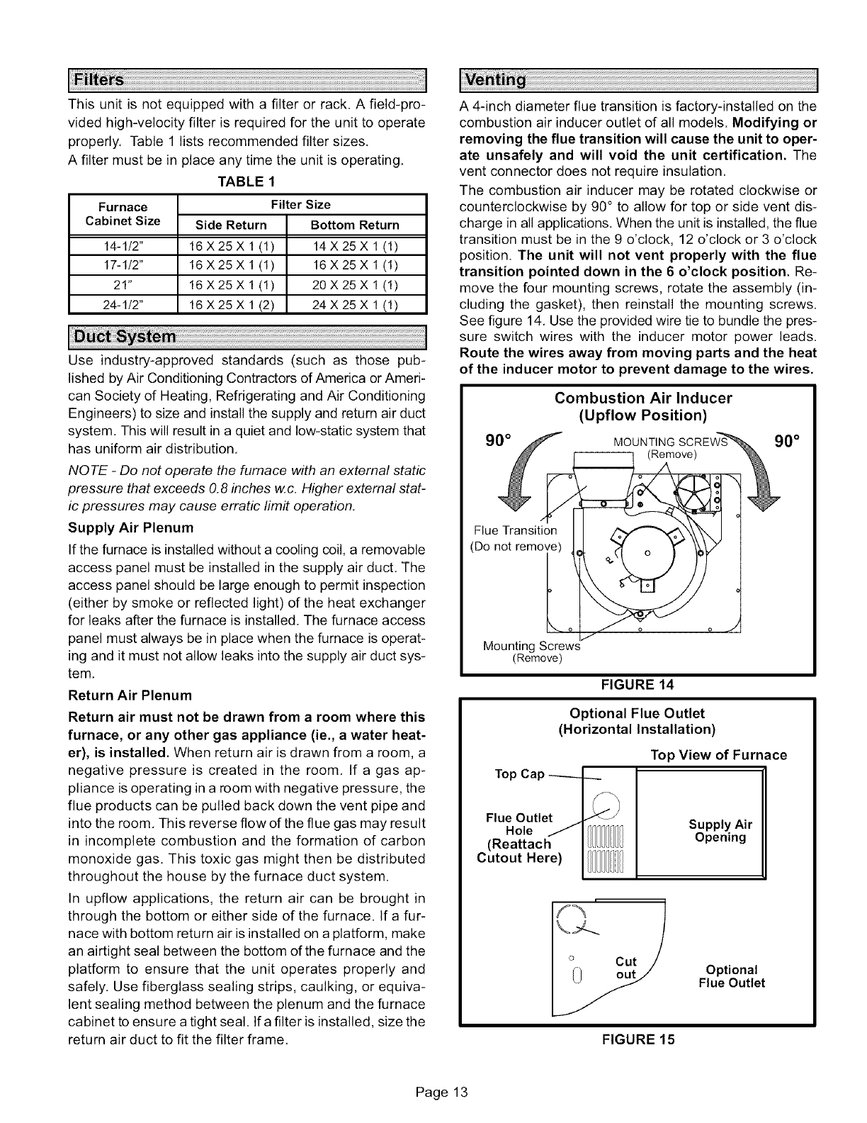
A 4-inch diameter flue transition is factory-installed on the
combustion air inducer outlet of all models. Modifying or
removing the flue transition will cause the unit to oper-
ate unsafely and will void the unit certification. The
vent connector does not require insulation.
The combustion air inducer may be rotated clockwise or
counterclockwise by 90° to allow for top or side vent dis-
charge in all applications. When the unit is installed, the flue
transition must be in the 9 o'clock, 12 o'clock or 3 o'clock
position. The unit will not vent properly with the flue
transition pointed down in the 6 o'clock position. Re-
move the four mounting screws, rotate the assembly (in-
cluding the gasket), then reinstall the mounting screws.
See figure 14. Use the provided wire tie to bundle the pres-
sure switch wires with the inducer motor power leads.
Route the wires away from moving parts and the heat
of the inducer motor to prevent damage to the wires.
Flue Transition
(Do not remove)
L
Mounting Screws
(Remove)
Combustion Air Inducer
(Upflow Position)
MOUNTING SCREW% 90 °
______ (Remove) _
FIGURE 14
Optional Flue Outlet
(Horizontal Installation)
Top Cap -----_.
f_
Flue Outlet _-J_'J
Hole
(Reattach IIII/! I
Cutout Here)
Top View of Furnace
Supply Air
Opening
FIGURE 15
Optional
Flue Outlet
Page 13
Usesheetmetalshearstoremovethecutoutfromtheside
ofthecabinet.Usethetwoprovidedsheetmetalscrewsto
installthecutoutonthetopcaptocovertheoriginalflue
outletopening.Seefigure15,
TheG60UHV(X)seriesunitsareclassifiedasfan-assisted
CategoryI furnaceswhenverticallyventedaccordingto
thelatesteditionof NationalFuelGasCode(NFPA54/
ANSI Z223.1) in the USA and the current standards of CSA
B149 Natural Gas and Propane Installation Codes in Can-
ada. A fan-assisted Category I furnace is an appliance
equipped with an integral mechanical means to either draw
or force combustion products through the combustion
chamber and/or heat exchanger.
NQ TE -Use these instructions as a guide. They do not su-
persede local codes, This furnace must be vented accord-
ing to all local codes these installation instructions, and the
provided venting tables in these instructions
The venting tables in this manual were extracted from the
National Fuel Gas Code (NFPA 54 /ANSI Z223,1 ) and are
provided as a guide for proper vent installation, Proper ap-
plication, termination, construction and location of vents
must conform to local codes having jurisdiction. In the ab-
sence of local codes, the NFGC serves as the defining doc-
ument,
Refer to the tables and the venting information contained in
these instructions to properly size and install the venting
system,
A, IMPORTANT
AWARNING
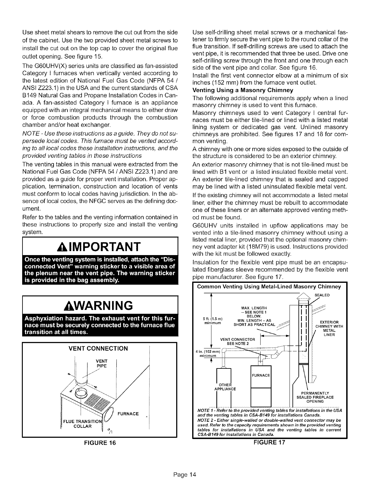
VENT CONNECTION
VENT
PIPE
J
FLUE TRANSITIC
COLLAR
FURNACE
FIGURE 16
Use self-drilling sheet metal screws or a mechanical fas-
tener to firmly secure the vent pipe to the round collar of the
flue transition. If self-drilling screws are used to attach the
vent pipe, it is recommended that three be used. Drive one
self-drilling screw through the front and one through each
side of the vent pipe and collar. See figure 16.
Install the first vent connector elbow at a minimum of six
inches (152 mm) from the furnace vent outlet,
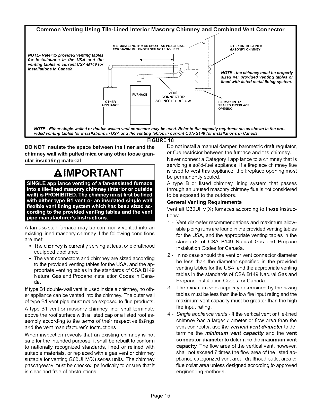
Venting Using a Masonry Chimney
The following additional requirements apply when a lined
masonry chimney is used to vent this furnace.
Masonry chimneys used to vent Category I central fur-
naces must be either tile-lined or lined with a listed metal
lining system or dedicated gas vent, Unlined masonry
chimneys are prohibited, See figures 17 and 18 for com-
mon venting.
A chimney with one or more sides exposed to the outside of
the structure is considered to be an exterior chimney.
An exterior masonry chimney that is not tile-lined must be
lined with B1 vent or a listed insulated flexible metal vent.
An exterior tile-lined chimney that is sealed and capped
may be lined with a listed uninsulated flexible metal vent,
If the existing chimney will not accommodate a listed metal
liner, either the chimney must be rebuilt to accommodate
one of these liners or an alternate approved venting meth-
od must be found.
G60UHV units installed in upflow applications may be
vented into a tile-lined masonry chimney without using a
listed metal liner, provided that the optional masonry chim-
ney vent adapter kit (18M79) is used. Instructions provided
with the kit must be followed exactly.
Insulation for the flexible vent pipe must be an encapsu-
lated fiberglass sleeve recommended by the flexible vent
pipe manufacturer, See figure 17,
Common Venting Using Metal-Lined Masonry Chimney
l SEALjD
MAX. LENGTH
+- SEE NOTE 1II
BELOW.
5_!15o,) MINLENGTH-AS II
rnm]rnurn SHORT AS PRACTICAL _i i EXTERIOR
___v i_-'_- ; CH_MNEYW_TH
II METAL
LINER
I',
4,n+{,02o, J
SEALED FIREPLACE
OPENING
NOTE 1-Refer to the provided venting tables for installations in the USA
and the venting tables in CSA-B149 for installations Canada.
NOTE 2 -Either single-walled or doable-walled vent connector may be
used. Refer to the capacity requirements shown in the provided venting
tables for installations in USA and the venting tables in current
CSA-B149 for installations in Canada.
FIGURE 17
Page 14
Common Venting Using Tile-Lined Interior Masonry Chimney and Combined Vent Connector
J
MINIMUM LENGTH = AS SHORT AS PRACTICAL. _N/ I I INTERIOR TILE=LINED
FOR MAXIMUM LENGTH SEE NOTE TO LEFT I I [ I MASONRY CHIMNEY
NOTE- Refer to provided venting tables I I J
for installations in the USA and the i= =" I ]I]J
venting tables in current CSA-B149 for F 1 ! 'l IJ_ _ _"_
installations in Canada. _ ' I_F_ 4--4 [/_ ]
H I ........... _ I A_ I NOTE-thechimneymustbeproperly
H _T L-_-- --_ I _ I ]sizedperprovided venting tables or
___ _ _ lined with llsted metal llning system.
I I FURNACE IVENT I
I I _ CONNECTORI I_
Ap_THAENRcE ._ SEE NOTE 1BELOW iiiMANDN_INTLYL A CE
NOTE -Either single-walled or double-walled vent connector may be used. Refer to the capacity requirements as shown in the pro-
vided venting tables for installations in USA and the venting tables in current CSA-B149 for installations in Canada.
FIGURE 18
DO NOT insulate the space between the liner and the Do not install a manual damper, barometric draft regulator,
chimney wall with puffed mica or any other loose gran-
ular insulating material
klMPORTANT
A fan-assisted furnace may be commonly vented into an
existing lined masonry chimney if the following conditions
are met:
• The chimney is currently serving at least one drafthood
equipped appliance
• The vent connectors and chimney are sized according
to the provided venting tables for the USA, and the ap-
propriate venting tables in the standards of CSA B149
Natural Gas and Propane Installation Codes in Cana-
da.
If type B1 double-wall vent is used inside a chimney, no oth-
er appliance can be vented into the chimney. The outer wall
of type B1 vent pipe must not be exposed to flue products.
A type B1 vent or masonry chimney liner shall terminate
above the roof surface with a listed cap or a listed roof as-
sembly according to the terms of their respective listings
and the vent manufacturer's instructions.
When inspection reveals that an existing chimney is not
safe for the intended purpose, it shall be rebuilt to conform
to nationally recognized standards, lined or relined with
suitable materials, or replaced with a gas vent or chimney
suitable for venting G60UHV(X) series units. The chimney
passageway must be checked periodically to ensure that it
is clear and free of obstructions.
or flue restrictor between the furnace and the chimney.
Never connect a Category I appliance to a chimney that is
servicing a solid-fuel appliance. If a fireplace chimney flue
is used to vent this appliance, the fireplace opening must
be permanently sealed.
A type B or listed chimney lining system that passes
through an unused masonry chimney flue is not considered
to be exposed to the outdoors.
General Venting Requirements
Vent all G60UHV(X) furnaces according to these instruc-
tions:
1 - Vent diameter recommendations and maximum allow-
able piping runs are found in the provided venting tables
for the USA, and the appropriate venting tables in the
standards of CSA B149 Natural Gas and Propane
Installation Codes for Canada.
2 - In no case should the vent or vent connector diameter
be less than the diameter specified in the provided
venting tables for the USA, and the appropriate venting
tables in the standards of CSA B149 Natural Gas and
Propane Installation Codes for Canada.
3 - The minimum vent capacity determined by the sizing
tables must be less than the low fire input rating and the
maximum vent capacity must be greater than the high
fire input rating.
4 - Single appliance vents - If the vertical vent or tile-lined
chimney has a larger diameter or flow area than the
vent connector, use the vertical vent diameter to de-
termine the minimum vent capacity and the vent
connector diameter to determine the maximum vent
capacity, The flow area of the vertical vent, however,
shall not exceed 7 times the flow area of the listed ap-
pliance categorized vent area, drafthood outlet area or
flue collar area unless designed according to approved
engineering methods.
Page 15
5- Multiple appliance vents - The flow area of the largest
section of vertical vent or chimney shall not exceed 7
times the smallest listed appliance categorized vent
area, drafthood outlet area or flue collar area unless de-
signed according to approved engineering methods.
6 - The entire length of single wall metal vent connector
shall be readily accessible for inspection, cleaning,
and replacement.
7 - Single appliance venting configurations with zero lat-
eral lengths (tables 3 and 4) are assumed to have no
elbows in the vent system. For all other vent configura-
tions, the vent system is assumed to have two 90 ° el-
bows. For each additional 90° elbow or equivalent (for
example two 45° elbows equal one 90° elbow) beyond
two, the maximum capacity listed in the venting table
should be reduced by 10% (0.90 x maximum listed ca-
pacity).
8 - The common venting tables (5, 6, 7, and 8) were gen-
erated using a maximum horizontal vent connector
length of 1-1/2 feet (.46 m) for each inch (25 mm) of
connector diameter as follows:
TABLE 2
Connector Diameter Maximum Horizontal
inches (mm) Connector Length feet (m)
3 (76) 4-1/2 (1.37)
4 (102) 6 (1.83)
5 (127) 7-1/2 (2.29)
6 (152) 9 (2.74)
7 (178) 10-1/2 (3.20)
9 - If the common vertical vent is offset, the maximum
common vent capacity listed in the common venting
tables should be reduced by 20%, the equivalent dtwo
90° elbows (0.80 x maximum common vent capacity).
The horizontal length of the offset shall not exceed
1-1/2 feet (.46 m) for each inch (25 mm) of common
vent diameter.
10 - The vent pipe should be as short as possible with the
least number of elbows and angles required to com-
plete the job. Route the vent connector to the vent us-
ing the shortest possible route.
11 - A vent connector shall be supported without any dips
or sags and shall slope a minimum of 1/4 inch (6.4 mm)
per linear foot (305 mm) of connector, back toward the
appliance.
12 - Vent connectors shall be firmly attached to the furnace
flue collar by self-drilling screws or other approved
means, except vent connectors of listed type B vent
material which shall be assembled according to the
manufacturer's instructions. Joints between sections
of single wall connector piping shall be fastened by
screws or other approved means.
13-When the vent connector used for Category I ap-
pliances must be located in or pass through a crawl-
space or other areas which may be cold, that portion of
the vent connector shall be constructed of listed
double-wall type B vent material or material having
equivalent insulation qualities.
14 - All venting pipe passing through floors, walls, and ceil-
ings must be installed with the listed clearance to com-
bustible materials and be fire stopped according to lo-
cal codes. In absence of local codes, refer to NFGC
(Z223.1).
15 - No portion of the venting system can extend into, or pass
through any circulation air duct or plenum.
16- Vent connectors serving Category I appliances shall
not be connected to any portion of mechanical draft
systems operating under positive pressure such as
Category Ill or IV venting systems.
17 - If vent connectors are combined prior to entering the
common vent, the maximum common vent capacity
listed in the common venting tables must be reduced by
10%, the equivalent of one 90° elbow (0.90 x maximum
common vent capacity).
18 - The common vent diameter must always be at least as
large as the largest vent connector diameter.
19 - In no case, shall the vent connector be sized more than
two consecutive table size diameters over the size of
the draft hood outlet or flue collar outlet.
20 - Do not install a manual damper, barometric draft regu-
lator or flue restrictor between the furnace and the
chimney.
21 - When connecting this appliance to an existing dedi-
cated or common venting system, you must inspect the
venting system's general condition and look for signs
of corrosion. The existing vent pipe size must conform
to these instructions and the provided venting tables
for the USA, and the appropriate venting tables in the
standards of CSA B149 Natural Gas and Propane
Installation Codes for Canada. If the existing venting
system does not meet these requirements, it must be
resized.
Page 16
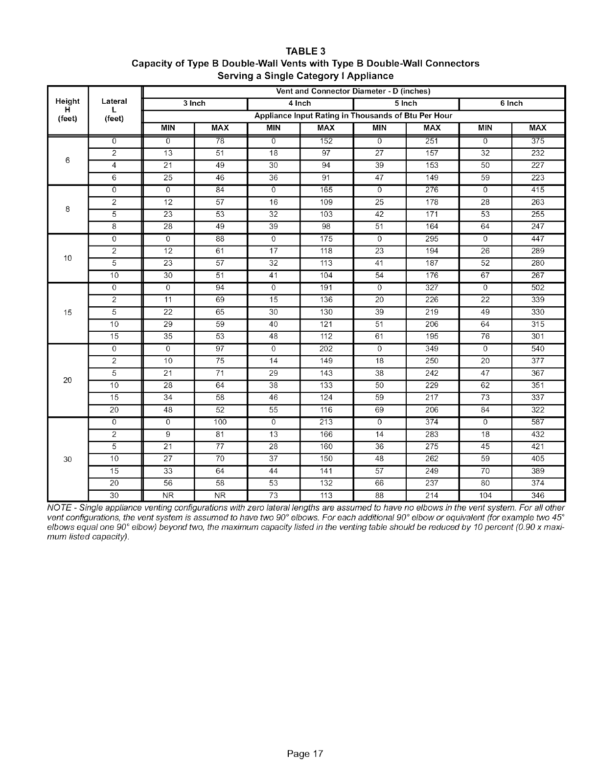
TABLE 3
Capacity of Type B Double-Wall Vents with Type B Double-Wall Connectors
Serving a Single Category I Appliance
Vent and Connector Diameter -D (inches)
Height Lateral 3 Inch 4 Inch 5 Inch 6 Inch
H L
(feet) (feet) Appliance Input Rating in Thousands of Btu Per Hour
MIN MAX MIN MAX MIN MAX MIN MAX
0 0 78 0 152 0 251 0 375
2 13 51 18 97 27 157 32 232
64 21 49 30 94 39 153 50 227
6 25 46 36 91 47 149 59 223
0 0 84 0 165 0 276 0 415
2 12 57 16 109 25 178 28 263
85 23 53 32 103 42 171 53 255
8 28 49 39 98 51 164 64 247
0 0 88 0 175 0 295 0 447
2 12 61 17 118 23 194 26 289
10 5 23 57 32 113 41 187 52 280
10 30 51 41 104 54 176 67 267
0 0 94 0 191 0 327 0 502
2 11 69 15 136 20 226 22 339
15 5 22 65 30 130 39 219 49 330
10 29 59 40 121 51 206 64 315
15 35 53 48 112 61 195 76 301
0 0 97 0 202 0 349 0 540
2 10 75 14 149 18 250 20 377
5 21 71 29 143 38 242 47 367
20 10 28 64 38 133 50 229 62 351
15 34 58 46 124 59 217 73 337
20 48 52 55 116 69 206 84 322
0 0 100 0 213 0 374 0 587
2 9 81 13 166 14 283 18 432
5 21 77 28 160 36 275 45 421
30 10 27 70 37 150 48 262 59 405
15 33 64 44 141 57 249 70 389
20 56 58 53 132 66 237 80 374
30 NR NR 73 113 88 214 104 346
NOTE -Single appliance venting configurations with zero lateral lengths are assumed to have no elbows in the vent system. For all other
vent configurations, the vent system is assumed to have two 90 °elbows. For each additional 90 °elbow or equivalent (for example two 45 °
elbows equal one 90 ° elbow) beyond two, the maximum capacity listed in the venting table should be reduced by 10 percent (0.90 x maxi-
mum listed capacity).
Page 17
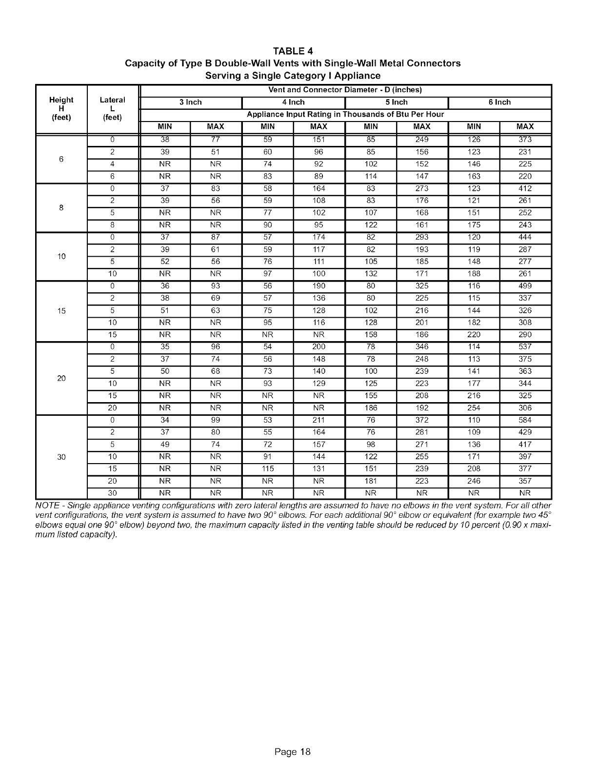
TABLE 4
Capacity of Type B Double-Wall Vents with Single-Wall Metal Connectors
Serving a Single Category I Appliance
Vent and Connector Diameter - D (inches)
Height Lateral 3 Inch 4 Inch 5 Inch 6 Inch
H L
(feet) (feet) Appliance Input Rating in Thousands of Btu Per Hour
MIN MAX MIN MAX MIN MAX MIN MAX
0 38 77 59 151 85 249 126 373
2 39 51 60 96 85 156 123 231
64 NR NR 74 92 102 152 146 225
6 NR NR 83 89 114 147 163 220
0 37 83 58 164 83 273 123 412
2 39 56 59 108 83 176 121 261
85 NR NR 77 102 107 168 151 252
8 NR NR 90 95 122 161 175 243
0 37 87 57 174 82 293 120 444
2 39 61 59 117 82 193 119 287
10 5 52 56 76 111 105 185 148 277
10 NR NR 97 100 132 171 188 261
0 36 93 56 190 80 325 116 499
2 38 69 57 136 80 225 115 337
15 5 51 63 75 128 102 216 144 326
10 NR NR 95 116 128 201 182 308
15 NR NR NR NR 158 186 220 290
0 35 96 54 200 78 346 114 537
2 37 74 56 148 78 248 113 375
5 50 68 73 140 100 239 141 363
20 10 NR NR 93 129 125 223 177 344
15 NR NR NR NR 155 208 216 325
20 NR NR NR NR 186 192 254 306
0 34 99 53 211 76 372 110 584
2 37 80 55 164 76 281 109 429
5 49 74 72 157 98 271 136 417
30 10 NR NR 91 144 122 255 171 397
15 NR NR 115 131 151 239 208 377
20 NR NR NR NR 181 223 246 357
30 NR NR NR NR NR NR NR NR
NOTE -Single appfiance venting configurations with zero lateral lengths are assumed to have no elbows in the vent system. For all other
vent configurations, the vent system is assumed to have two 90°elbows. For each additional 90°elbow or equivalent (for example two 45 °
elbows equal one 90 °elbow) beyond two, the maximum capacity listed in the venting table should be reduced by 10percent (0.90 x maxi-
mum listed capacity).
Page 18
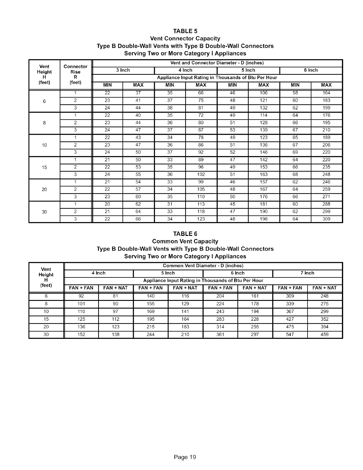
TABLE 5
Vent Connector Capacity
Type B Double-Wall Vents with Type B Double-Wall Connectors
Serving Two or More Category I Appliances
Vent and Connector Diameter -D (inches)
Vent Connector
Height Rise 3 Inch 4 Inch 5 Inch 6 Inch
H R Appliance Input Rating in Thousands of Btu Per Hour
(feet) (feet) MIN MAX MIN MAX MIN MAX MIN MAX
1 22 37 35 66 46 106 58 164
6 2 23 41 37 75 48 121 60 183
3 24 44 38 81 49 132 62 199
1 22 40 35 72 49 114 64 176
8 2 23 44 36 80 51 128 66 195
3 24 47 37 87 53 139 67 210
1 22 43 34 78 49 123 65 189
10 2 23 47 36 86 51 136 67 206
3 24 50 37 92 52 146 69 220
1 21 50 33 89 47 142 64 220
15 2 22 53 35 96 49 153 66 235
3 24 55 36 102 51 163 68 248
1 21 54 33 99 46 157 62 246
20 2 22 57 34 105 48 167 64 259
3 23 60 35 110 50 176 66 271
1 20 62 31 113 45 181 60 288
30 2 21 64 33 118 47 190 62 299
3 22 66 34 123 48 198 64 309
TABLE 6
Common Vent Capacity
Type B Double-Wall Vents with Type B Double-Wall Connectors
Serving Two or More Category I Appliances
Common Vent Diameter - D (inches)
Vent
Height 4 Inch 5 Inch 6 Inch 7 Inch
H Appliance Input Rating in Thousands of Btu Per Hour
(feet) FAN + FAN FAN + NAT FAN + FAN FAN + NAT FAN + FAN FAN + NAT FAN + FAN FAN + NAT
6 92 81 140 116 204 161 309 248
8 101 90 155 129 224 178 339 275
10 110 97 169 141 243 194 367 299
15 125 112 195 164 283 228 427 352
20 136 123 215 183 314 255 475 394
30 152 138 244 210 361 297 547 459
Page 19
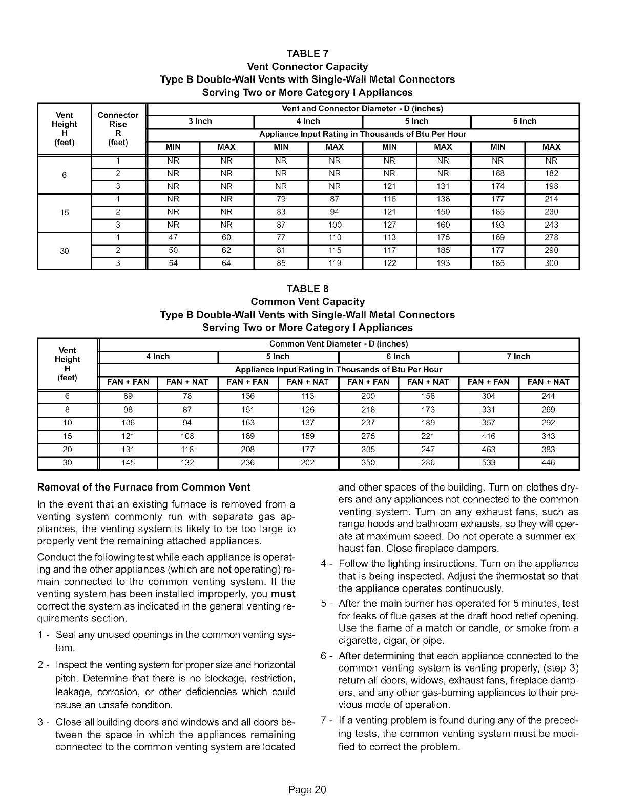
TABLE 7
Vent Connector Capacity
Type B Double-Wall Vents with Single-Wall Metal Connectors
Serving Two or More Category I Appliances
Vent and Connector Diameter - D (inches)
Vent Connector
Height Rise 3 Inch 4 Inch 5 Inch 6 Inch
H R Appliance Input Rating in Thousands of Btu Per Hour
(feet) (feet) MIN MAX MIN MAX MIN MAX MIN MAX
I NR NR NR NR NR NR NR NR
6 2 NR NR NR NR NR NR 168 182
3 NR NR NR NR 121 131 174 198
1 NR NR 79 87 116 138 177 214
15 2 NR NR 83 94 121 150 185 230
3 NR NR 87 100 127 160 193 243
1 47 60 77 110 113 175 169 278
30 2 50 62 81 115 117 185 177 290
3 54 64 85 119 122 193 185 300
TABLE 8
Common Vent Capacity
Type B Double-Wall Vents with Single-Wall Metal Connectors
Serving Two or More Category I Appliances
Common Vent Diameter - D (inches)
Vent
Height 4 Inch 5 Inch 6 Inch 7 Inch
H Appliance Input Rating in Thousands of Btu Per Hour
(feet) FAN + FAN FAN + NAT FAN + FAN FAN + NAT FAN + FAN FAN + NAT FAN + FAN FAN + NAT
6 89 78 136 113 200 158 304 244
8 98 87 151 126 218 173 331 269
10 106 94 163 137 237 189 357 292
15 121 108 189 159 275 221 416 343
20 131 118 208 177 305 247 463 383
30 145 132 236 202 350 286 533 446
Removal of the Furnace from Common Vent
In the event that an existing furnace is removed from a
venting system commonly run with separate gas ap-
pliances, the venting system is likely to be too large to
properly vent the remaining attached appliances,
Conduct the following test while each appliance is operat-
ing and the other appliances (which are not operating) re-
main connected to the common venting system. If the
venting system has been installed improperly, you must
correct the system as indicated in the general venting re-
quirements section.
1 - Seal any unused openings in the common venting sys-
tem,
2 - Inspect the venting system for proper size and horizontal
pitch, Determine that there is no blockage, restriction,
leakage, corrosion, or other deficiencies which could
cause an unsafe condition,
3 - Close all building doors and windows and all doors be-
tween the space in which the appliances remaining
connected to the common venting system are located
and other spaces of the building. Turn on clothes dry-
ers and any appliances not connected to the common
venting system. Turn on any exhaust fans, such as
range hoods and bathroom exhausts, so they will oper-
ate at maximum speed. Do not operate a summer ex-
haust fan. Close fireplace dampers.
4 - Follow the lighting instructions, Turn on the appliance
that is being inspected, Adjust the thermostat so that
the appliance operates continuously,
5 - After the main burner has operated for 5 minutes, test
for leaks of flue gases at the draft hood relief opening,
Use the flame of a match or candle, or smoke from a
cigarette, cigar, or pipe,
6 - After determining that each appliance connected to the
common venting system is venting properly, (step 3)
return all doors, widows, exhaust fans, fireplace damp-
ers, and any other gas-burning appliances to their pre-
vious mode of operation,
7 - If a venting problem is found during any of the preced-
ing tests, the common venting system must be modi-
fied to correct the problem,
Page 20
Resizethecommonventingsystemto theminimum
ventpipesizedeterminedbyusingtheappropriate
tablesinAppendixG.(Theseareinthecurrentstan-
dardsoftheNationalFuelGasCodeANSIZ223.1in
theUSA,andtheappropriateCategory1NaturalGas
andPropaneappliancesventingsizingtablesinthe
currentstandardsof theCSAB149NaturalGasand
PropaneInstallationCodesinCanada.)
XkCAUTION
3 - The gas piping must not run in or through air ducts,
clothes chutes, gas vents or chimneys, dumb waiters,
or elevator shafts.
4 - The piping should be sloped 1/4 inch (6,4 mm) per 15
feet (4,57 m) upward toward the meter from the fur-
nace. The piping must be supported at proper intervals
[every 8 to 10 feet (2.44 to 3.01 m)] with suitable hang-
ers or straps, Install a drip leg inside vertical pipe runs
to the unit.
5 - A 1/8" N.RT. plugged tap or pressure post is located
on the gas valve to facilitate test gauge connection.
See figures 26 and 27.
6 - In some localities, codes may require the installation of
a manual main shut-off valve and union (furnished by
the installer) external to the unit, The union must be of
the ground joint type.
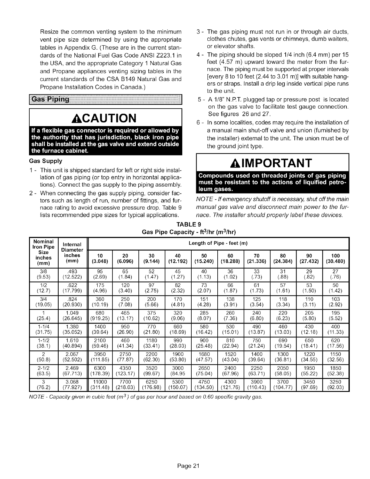
Gas Supply
1 - This unit is shipped standard for left or right side instal-
lation of gas piping (or top entry in horizontal applica-
tions). Connect the gas supply to the piping assembly.
2 - When connecting the gas supply piping, consider fac-
tors such as length of run, number of fittings, and fur-
nace rating to avoid excessive pressure drop. Table 9
lists recommended pipe sizes for typical applications.
klMPORTANT
NOTE -If emergency shutoff is necessa04 shut off the main
manual gas valve and disconnect main power to the fur-
nace. The installer should properly label these devices.
Nominal
IronPipe Internal
Size Diameter
inches inches
(ram) (ram)
3/8
(9.53)
1/2
(12.7)
3/4
(19.05)
1
(25.4)
1-1/4
(31.75)
1-1/2
(38.1)
2
(50.8)
2-1/2
(63.5)
3
(76.2)
NOTE -Capacity given in
TABLE 9
Gas Pipe Capacity -ft3/hr (m3/hr)
Length of Pipe - feet (m)
10 20 30 40 50 60 70 80 90 lOO
(3.048) (6.096) (9.144) (12.192) (15.240) (18.288) (21.336) (24.384) (27.432) (30.480)
.493 95 65
(12.522) (2.69) (1.84)
.622 175 120
(17.799) (4.96) (3.40)
.824 360 250
(20.930) (10.19) (7.08)
1.049 680 465
(26.645) (919.25) (13.17)
1.380 1400 950
(35.052) (39.64) (26.90)
1.610 2100 460
(40.894) (59.46) (41.34)
2.067 3950 2750
(52.502) (111.85) (77.87)
2.469 6300 4350
(67.713) (178.39) (123.17)
3.068 11000 7700
(77.927) (311.48) (218.03)
cubic feet
52
(1.47)
97
(2.75)
2OO
(5.66)
375
(10.62)
77O
(21.80)
1180
(33.41)
2200
(62.30)
3520
(99.67)
6250
(176.98)
45
(1.27)
82
(2.32)
170
(4.81)
32O
(9.06)
66O
(18.69)
990
(28.03)
1900
(53.80)
3000
(84.95
5300
(150.07)
4O
(1.13)
73
(2.07)
151
(4.28)
285
(8.07)
580
(16.42)
9OO
(25.48)
1680
(47.57)
2650
(75.04)
4750
(134.50)
36
(1.02)
66
(1.87)
138
(3.91)
26O
(7.36)
53O
(15.01)
810
(22.94)
1520
(43.04)
2400
(67.96)
4300
(121.76)
33
(.73)
61
(1.73)
125
(3.54)
24O
(6.80)
490
(13.87)
75O
(21.24)
1400
(39.64)
2250
(63.71)
3900
(110.43)
(m3 ) of gas per hour and based on O.60 specific gravity gas.
31
(.88)
57
(1.61)
118
(3.34)
22O
(6.23)
46O
(13.03)
69O
(19.54)
1300
(36.81)
2050
(58.05)
3700
(104.77)
29
(.82)
53
(1.5o)
110
(3.11)
2O5
(5.80)
430
(12.18)
65O
(18.41)
1220
(34.55)
1950
(55.22)
3450
(97.69)
27
(.76)
5O
(1.42)
103
(2.92)
195
(5.52)
400
(11.33)
62O
(17.56)
1150
(32.56)
1850
(52.38)
3250
(92.03)
Page 21
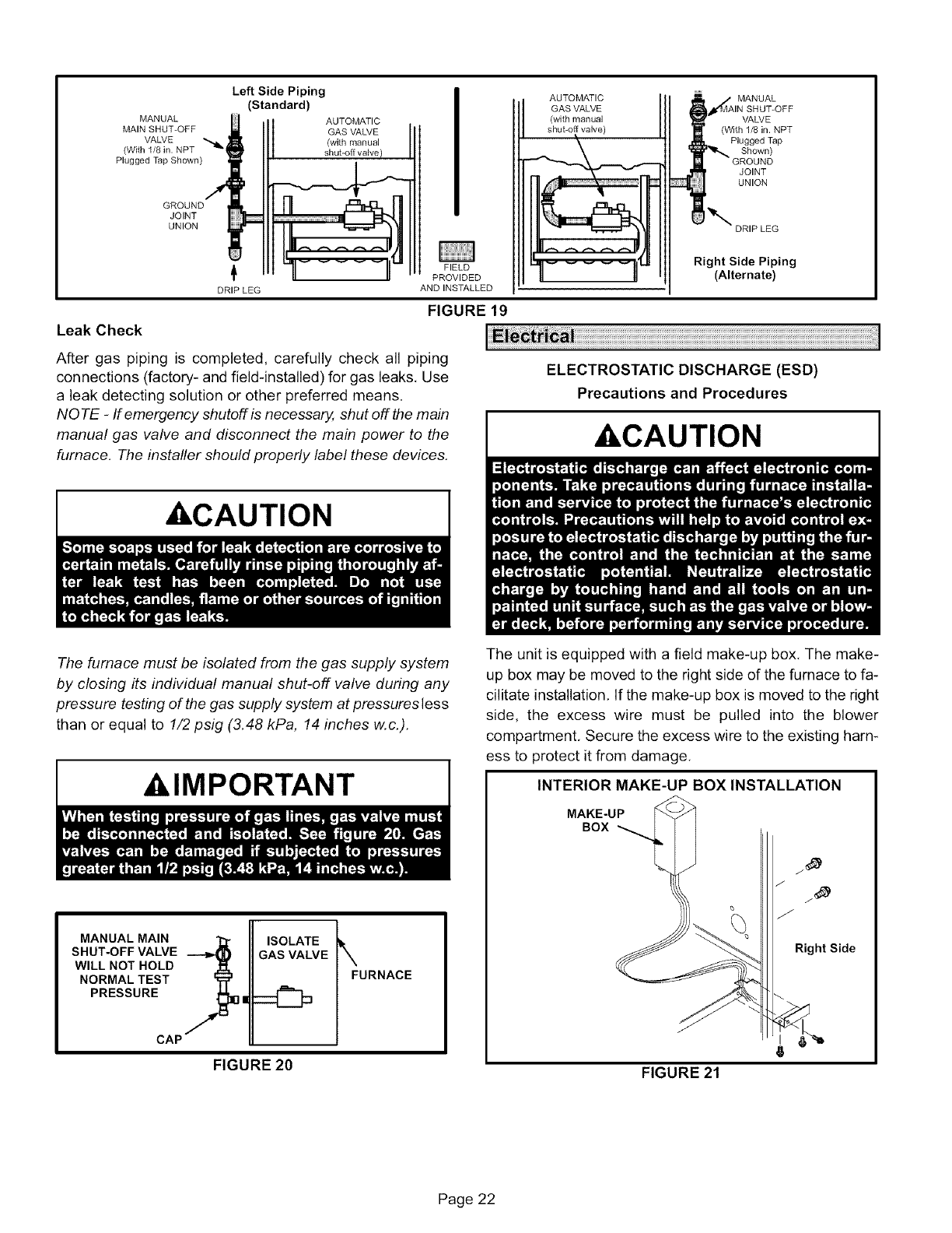
MANUAL
MAIN SHUT-OFF
VALVE
(With 1/8 in. NPT
Plugged Tap Shown)
GROUND
JOINT
UNION
Left Side Piping
(Standard)
AUTOMATIC
GAS VALVE
(with manual
shut-off valve)
AUTOMATIC MANUAL
GAS VALVE SHUT-OFF
(with manual VALVE
shuboff valve) (With 1/8 in. NPT
Plugged Tap
Shown)
JOINT
UNION
_DRIP LEG
DRIP LEG
FIELD
PROVIDED
ANDINSTALLED
FIGURE 19
Leak Check
After gas piping is completed, carefully check all piping
connections (factory- and field-installed) for gas leaks, Use
a leak detecting solution or other preferred means.
NOTE -If emergency shutoff is necessa04 shut off the main
manual gas valve and disconnect the main power to the
furnace. The installer should properly label these devices.
Right Side Piping
(Alternate)
ELECTROSTATIC DISCHARGE (ESD)
Precautions and Procedures
kCAUTION
,CAUTION
The furnace must be isolated from the gas supply system
by closing #s individual manual shut-off valve during any
pressure testing of the gas supply system at pressures less
than or equal to 1/2 psig (3.48 kPa, 14 inches w.c.).
,IMPORTANT
MANUAL MAIN
SHUT-OFF VALVE
WILL NOT HOLD
NORMAL TEST
PRESSURE |
CAP
ISOLATE
GAS VALVE
FIGURE 20
\FURNACE
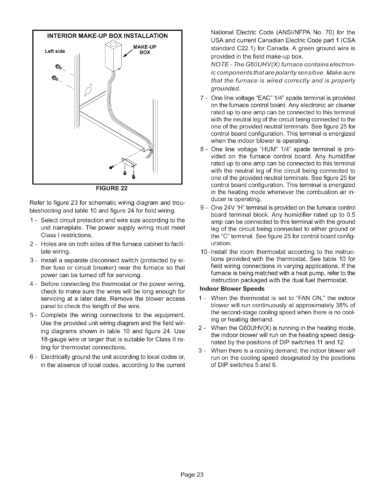
The unit is equipped with a field make-up box, The make-
up box may be moved to the right side of the furnace to fa-
cilitate installation, If the make-up box is moved to the right
side, the excess wire must be pulled into the blower
compartment, Secure the excess wire to the existing harn-
ess to protect it from damage.
INTERIOR MAKE-UP BOX INSTALLATION
MAKE-UP
BOX
6
FIGURE 21
Page 22
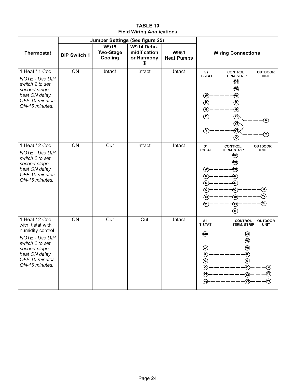
INTERIORMAKE-UP BOX INSTALLATION
Left side MAKE-UP
JBOX
FIGURE 22
Refer to figure 23 for schematic wiring diagram and trou-
bleshooting and table 10 and figure 24 for field wiring,
1 - Select circuit protection and wire size according to the
unit nameplate. The power supply wiring must meet
Class I restrictions,
2 - Holes are on both sides of the furnace cabinet to facili-
tate wiring,
3 - Install a separate disconnect switch (protected by ei-
ther fuse or circuit breaker) near the furnace so that
power can be turned off for servicing,
4 - Before connecting the thermostat or the power wiring,
check to make sure the wires will be long enough for
servicing at a later date, Remove the blower access
panel to check the length of the wire,
5- Complete the wiring connections to the equipment.
Use the provided unit wiring diagram and the field wir-
ing diagrams shown in table 10 and figure 24, Use
18-gauge wire or larger that is suitable for Class II ra-
ting for thermostat connections,
6 - Electrically ground the unit according to local codes or,
in the absence of local codes, according to the current
National Electric Code (ANSI/NFPA No, 70) for the
USA and current Canadian Electric Code part 1 (CSA
standard C22.1) for Canada, A green ground wire is
provided in the field make-up box,
NOTE- The G6OUHV(X) furnace contains electron-
ic compon en ts that are polarity sen sitive, Make sure
that the furnace is wired correctly and is properly
grounded,
7 - One line voltage "EAC" 1/4" spade terminal is provided
on the furnace control board. Any electronic air cleaner
rated up to one amp can be connected to this terminal
with the neutral leg dthe circuit being connected to the
one of the provided neutral terminals. See figure 25 for
control board configuration, This terminal is energized
when the indoor blower is operating,
8- One line voltage *'HUM" 1/4" spade terminal is pro-
vided on the furnace control board. Any humidifier
rated up to one amp can be connected to this terminal
with the neutral leg of the circuit being connected to
one of the provided neutral terminals. See figure 25 for
control board configuration. This terminal is energized
in the heating mode whenever the combustion air in-
ducer is operating.
9 - One 24V "H" terminal is provided on the furnace control
board terminal block. Any humidifier rated up to 0.5
amp can be connected to this terminal with the ground
leg of the circuit being connected to either ground or
the "C" terminal. See figure 25 for control board config-
uration.
10-Install the room thermostat according to the instruc-
tions provided with the thermostat, See table 10 for
field wiring connections in varying applications. If the
furnace is being matched with a heat pump, refer to the
instruction packaged with the dual fuel thermostat,
Indoor Blower Speeds
1 - When the thermostat is set to "FAN ON," the indoor
blower will run continuously at approximately 38% of
the second-stage cooling speed when there is no cool-
ing or heating demand,
2 - When the G60UHV(X) is running in the heating mode,
the indoor blower will run on the heating speed desig-
nated by the positions of DIP switches 11 and 12.
3 - When there is a cooling demand, the indoor blower will
run on the cooling speed designated by the positions
of DIP switches 5 and 6,
Page 23
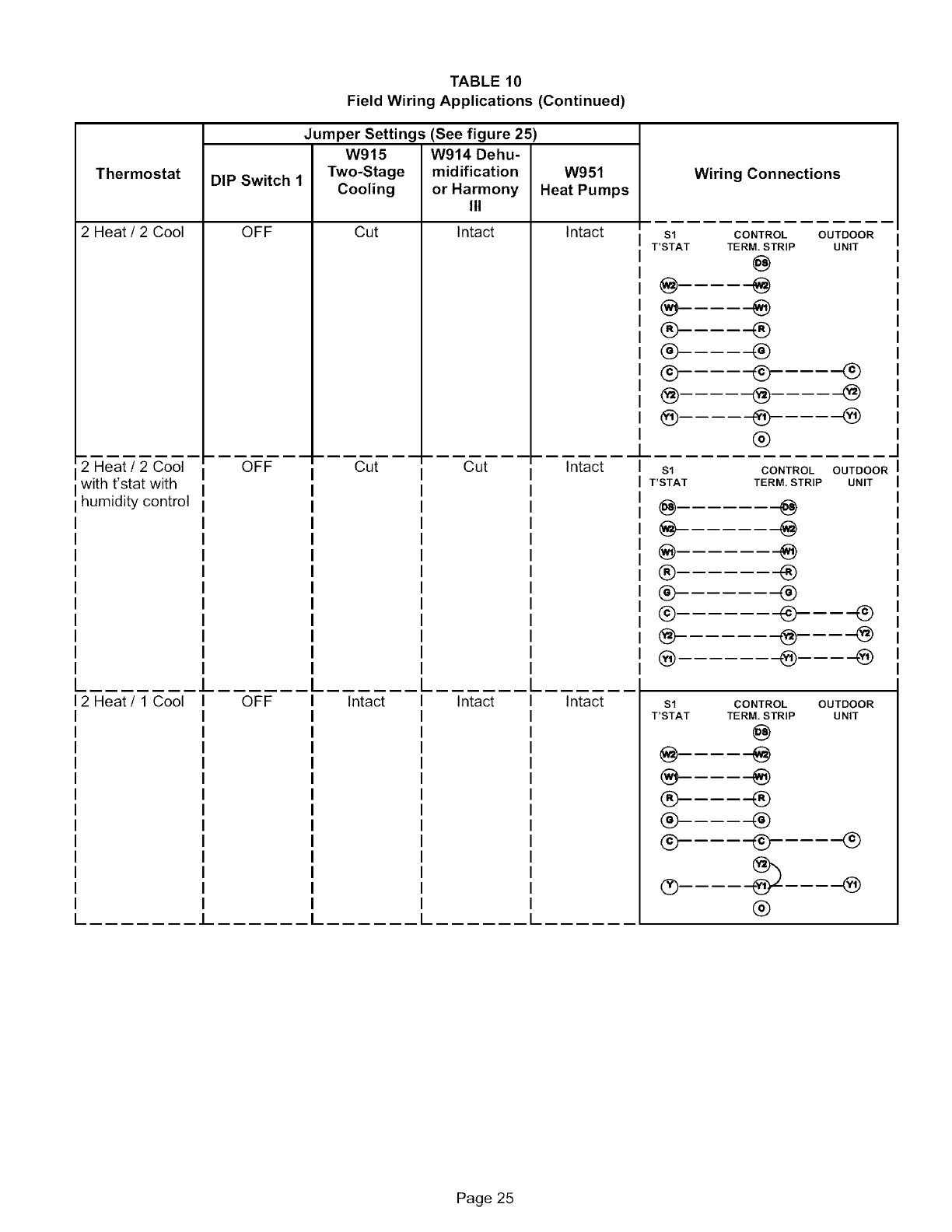
Thermostat
1 Heat/1 Cool
NOTE -Use DiP
switch 2to set
second-stage
heat ON delay.
QFF-IO minutes.
ON-15 minutes.
1 Heat /2 Cool
NOTE -Use DIP
switch 2 to set
second-stage
heat QN delay.
OFF-IO minutes.
ON-15 minutes.
1 Heat /2 Cool
with t'stat with
humidity control
NOTE -Use DIP
switch 2 to set
second-stage
heat ON delay.
QFF-fO minutes.
ON-15 minutes.
DIP Switch 1
ON
ON
ON
TABLE 10
Field Wiring Applications
Jumper Settings (See figure 25)
W915
Two-Stage
Cooling
Intact
Cut
Cut
W914 Dehu-
midification
or Harmony
III
Intact
Intact
Cut
W951
Heat Pumps
Intact
Intact
Intact
Wiring Connections
Sl CONTROL
T'STAT TERM. STRIP
@
®
®
®______
® _,
%
®
Sl CONTROL
T'STAT TERM. STRIP
@
®
® ®
® ®
@ ®
@. @
@
$1
T'STAT
@
®
®
®
@
OUTDOOR
UNIT
®
®
OUTDOOR
UNIT
®
@
@
CONTROL OUTDOOR
TERM. STRIP UNIT
@
®
®
_---_
@---@
®---_
Page 24
Thermostat
2 Heat /2 Cool
2 Heat /2 Cool
with t'stat with
humidity control
L
12 Heat /1 Cool
L
TABLE 10
Field Wiring Applications (Continued)
Jumper Settings (See figure 25)
W915 W914 Dehu-
DIP Switch 1 Two-Stage midification W951
Cooling or Harmony Heat Pumps
III
OFF Cut Intact Intact
OFF Cut Cut Intact
OFF Intact Intact Intact
$1
T'STAT
®
®
®
@.
@-
$1
T'STAT
@
@.
®.
®
®.
@
Wiring Connections
CONTROL
TERM. STRIP
@
®
®
@
®
®
OUTDOOR
UNIT
®
@
@
CONTROL OUTDOOR
TERM. STRIP UNIT
@
@
®
®®
@----@
®----@
$1 CONTROL OUTDOOR
T'STAT TERM. STRIP UNIT
@
® ®
0- 4_- @
®
Page 25
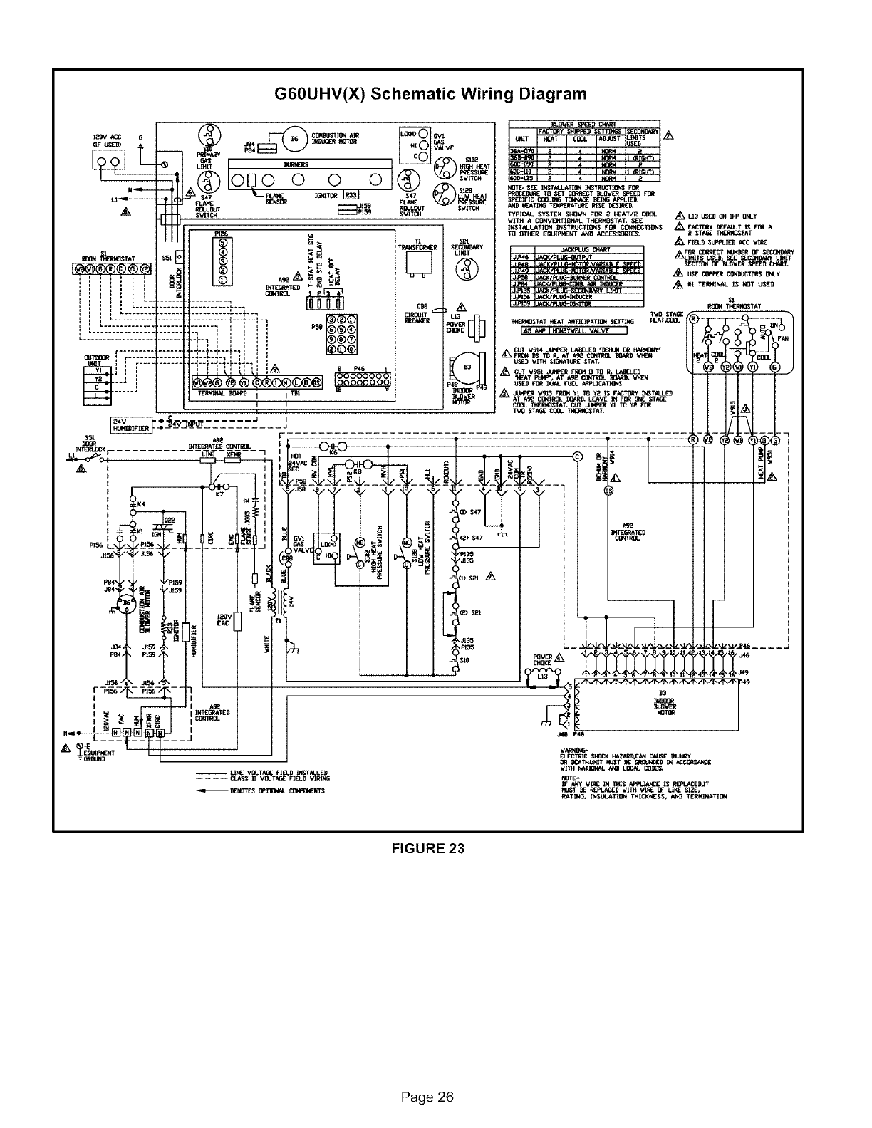
G60UHV(X) Schematic Wiring Diagram
FIGURE 23
Page 26

TYPICAL G60UHV(X) FIELD WIRING DIAGRAM
USE COPPER CONDUCTORS ONLY.
D _ FIELD INSTALLED CLASS II 24V
FIELD INSTALLED LINE VOLTAGE
t20V ACC G
N...,,e-i.
LI ...,m.ili--
= E
THERMOSTAT $51
I@@@_)©@@1 =_
f,i J
= i = I c.....
]_ ...............
L_t.U.._HH_-H2L _.H_-i
i. .........................
r...............
I
t_---- J
_-e 24V IN_U'T......
_CQHBUSTIQN AIR
J84 INDUCE'R HOTOR
PR]HARY P84 VALVE
oQ%o
GAS BURNERS HIGH HEAT
0 0 SVITCH
FLAME SENSOR 3t59
RDLLOUT __P159 RQLLDUT $_/ITCH
$VITCH
SVITCH
PtSS _Tt $21
_i TRANSFOR_R SEC_Y
LIMIT
INTEGRATED
CONTROL !2
.......... L._. C_8
.........,, , , _ ?_1111
.d.-r-J-_..÷_-
IIHDTI_
t
FIGURE 24
TWO-STAGE, VARIABLE SPEED INTEGRATED CONTROL BOARD
I OOOq
STATUS=
E-COW-
DIAGNOSTIC
LEDs
HEATING
DIP
SWITCHES
sl
INDOOR
BLOWERDIP
SWITCHES
ON-BOARD
JUMPERS
1/4" QUICK CONNECT TERMINALS
HUM : 120 VAC OUTPUT TO HUMIDIFIER
XMFR :12O VAC OUTPUT TO TRANSFORMER
LI :120 VAC INPUT TO CONTROL
CIRC : 120 VAC OUTPUT TO CIRCULATING BLOWER
EAC : 120 VAC OUTPUT TO ELECTRONIC AIR CLEANER
NEUTRALS= 120 VAC NEUTRAL
THERMOSTAT CONNECTIONS (TB1)
DS: DEHUMIDIFICATIONSIGNAL
W2: HEATDEMANDFROM2NDSTAGET'STAT
Wl: HEAT DEMAND FROM IST STAGE T'STAT
R: CLASS 2 VOLTAGE TO THERMOSTAT
G: MANUAL FAN FROM T'STAT
C: THERMOSTATSIGNAL GROUND CONNECTED TO TRANSFORMER
GROUND (TR) & CHASIS GROUND (GRD)
YI: THERMOSTAT Is_"STAGE COOL SIGNAL
Y2: THERMOSTAT2nd STAGE COOL SIGNAL
0--THERMOSTATSIGNAL TO HEAT PUMP REVERSINGVALVE
H= 24V HUMIDIFIER OUTPUT
L= LENNOX SYSTEM OPERATION MONITOR
1= FUTURE USE
DIP SWITCH FUNCTIONS
HTG DIP SWITCH(ES)
1
2
3 and 4
INDOOR BLOWER
DIP SWITCH(ES)
FUNCTION
T'stat Heat Staqes (sin qle or two-staqe)
Second Staqe ON Delay (sin qle-staqe t'stat)
Heatinq Fan OFF Delay
FUNCTION
5 and 6
7 and 8
9 and 10
11 and 12
Coolinq Mode Blower Speed
Blower Speed Adiustment
Cooling Mode Blower Ramping Profile
Heating Mode Blower Speed
FIGURE 25
Page 27
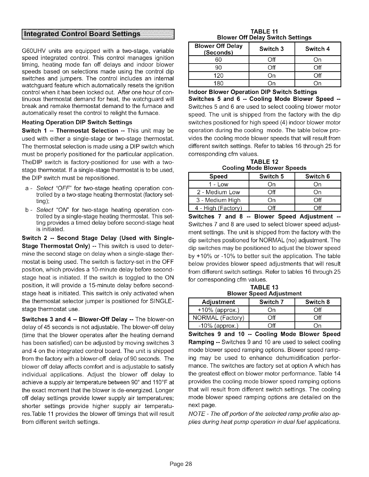
G60UHVunitsareequippedwitha two-stage,variable
speedintegratedcontrol.Thiscontrolmanagesignition
timing,heatingmodefan offdelaysandindoorblower
speedsbasedonselectionsmadeusingthecontroldip
switchesandjumpers.Thecontrolincludesan internal
watchguardfeaturewhichautomaticallyresetstheignition
controlwhenithasbeenlockedout.Afteronehourofcon-
tinuousthermostatdemandfor heat,thewatchguardwill
breakandremakethermostatdemandto thefurnaceand
automaticallyresetthecontrolto relightthefurnace.
HeatingOperationDIPSwitchSettings
Switch1 -- ThermostatSelection-- Thisunitmaybe
usedwitheithera single-stageor two-stagethermostat.
ThethermostatselectionismadeusingaDIPswitchwhich
mustbeproperlypositionedfortheparticularapplication.
TheDIPswitchis factory-positionedfor usewitha two-
stagethermostat.Ifasingle-stagethermostatistobeused,
theDIPswitchmustberepositioned,
a- Select "OFF" for two-stage heating operation con-
trolled by a two-stage heating thermostat (factory set-
ting);
b- Select "ON" for two-stage heating operation con-
trolled by a single-stage heating thermostat, This set-
ting provides a timed delay before second-stage heat
is initiated,
Switch 2 -- Second Stage Delay (Used with Single-
Stage Thermostat Only) -- This switch is used to deter-
mine the second stage on delay when a single-stage ther-
mostat is being used. The switch is factory-set in the OFF
position, which provides a 10-minute delay before second-
stage heat is initiated, If the switch is toggled to the ON
position, it will provide a 15-minute delay before second-
stage heat is initiated, This switch is only activated when
the thermostat selector jumper is positioned for SINGLE-
stage thermostat use,
Switches 3 and 4 -- Blower-Off Delay -- The blower-on
delay of 45 seconds is not adjustable. The blower-off delay
(time that the blower operates after the heating demand
has been satisfied) can be adjusted by moving switches 3
and 4 on the integrated control board, The unit is shipped
from the factory with a blower-off delay of 90 seconds, The
blower off delay affects comfort and is adjustable to satisfy
individual applications. Adjust the blower off delay to
achieve a supply air temperature between 90° and 110°F at
the exact moment that the blower is de-energized. Longer
off delay settings provide lower supply air temperatures;
shorter settings provide higher supply air temperatu-
res,Table 11 provides the blower off timings that will result
from different switch settings,
TABLE 11
Blower Off Delay Switch Settings
Blower Off Delay Switch 3 Switch 4
(Seconds)
60 Off On
90 Off Off
120 On Off
180 On On
Indoor Blower Operation DIP Switch Settings
Switches 5 and 6-- Cooling Mode Blower Speed --
Switches 5 and 6 are used to select cooling blower motor
speed. The unit is shipped from the factory with the dip
switches positioned for high speed (4) indoor blower motor
operation during the cooling mode. The table below pro-
vides the cooling mode blower speeds that will result from
different switch settings. Refer to tables 16 through 25 for
corresponding cfm values,
TABLE 12
Cooling Mode Blower Speeds
Speed Switch 5 Switch 6
1 - Low On On
2 - Medium Low Off On
3 - Medium High On Off
4 - High (Factory) Off Off
Switches 7 and 8-- Blower Speed Adjustment --
Switches 7 and 8 are used to select blower speed adjust-
ment settings. The unit is shipped from the factory with the
dip switches positioned for NORMAL (no) adjustment, The
dip switches may be positioned to adjust the blower speed
by +10% or -10% to better suit the application, The table
below provides blower speed adjustments that will result
from different switch settings. Refer to tables 16 through 25
for corresponding cfm values,
TABLE 13
Blower Speed Adjustment
Adjustment Switch 7 Switch 8
+10% (approx,) On Off
NORMAL (Factory) Off Off
-10% (approx,) Off On
Switches 9 and 10 -- Cooling Mode Blower Speed
Ramping -- Switches 9 and 10 are used to select cooling
mode blower speed ramping options, Blower speed ramp-
ing may be used to enhance dehumidification perfor-
mance. The switches are factory set at option A which has
the greatest effect on blower motor performance. Table 14
provides the cooling mode blower speed ramping options
that will result from different switch settings, The cooling
mode blower speed ramping options are detailed on the
next page,
NOTE -The off portion of the selected ramp profile also ap-
plies during heat pump operation in dual fuel applications,
Page 28
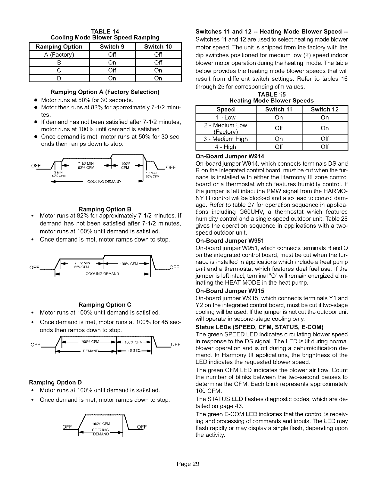
TABLE 14
Cooling Mode Blower Speed Ramping
Ramping Option Switch 9Switch 10
A (Factory) Off Off
B On Off
C Off On
D On On
Ramping Option A (Factory Selection)
• Motor runs at 50% for 30 seconds.
• Motor then runs at 82% for approximately 7-1/2 minu-
tes.
• If demand has not been satisfied after 7-1/2 minutes,
motor runs at 100% until demand is satisfied.
• Once demand is met, motor runs at 50% for 30 sec-
onds then ramps down to stop.
71/2MIN _ 100% __
82% CFM CFM OFF
COOL,NGDEMAND
Ramping Option B
• Motor runs at 82% for approximately 7-1/2 minutes. If
demand has not been satisfied after 7-1/2 minutes,
motor runs at 100% until demand is satisfied.
• Once demand is met, motor ramps down to stop.
(
-- 7 1/2 MIN _ 100% CFM
OFF 82%CFM /OFF
COOLING DEMAND --'1_"
Ramping Option C
• Motor runs at 100% until demand is satisfied.
• Once demand is met, motor runs at 100% for 45 sec-
onds then ramps down to stop.
._p-- 100% CFM --
OFF OFF
-- DEMAND
Ramping Option D
• Motor runs at 100% until demand is satisfied.
• Once demand is met, motor ramps down to stop.
100% CFM _OFF
COOLING
DEMAND
Switches 11 and 12 -- Heating Mode Blower Speed --
Switches 11and 12 are used to select heating mode blower
motor speed, The unit is shipped from the factory with the
dip switches positioned for medium low (2) speed indoor
blower motor operation during the heating mode. The table
below provides the heating mode blower speeds that will
result from different switch settings, Refer to tables 16
through 25 for corresponding cfm values,
TABLE 15
Heating Mode Blower Speeds
Speed Switch 11 Switch 12
1 - Low On On
2 - Medium Low Off On
(Factory)
3 - Medium High On Off
4 - High Off Off
On-Board Jumper W914
On-board jumper W914, which connects terminals DS and
R on the integrated control board, must be cut when the fur-
nace is installed with either the Harmony III zone control
board or a thermostat which features humidity control, If
the jumper is left intact the PMW signal from the HARMO-
NY Ill control will be blocked and also lead to control dam-
age. Refer to table 27 for operation sequence in applica-
tions including G60UHV, a thermostat which features
humidity control and a single-speed outdoor unit. Table 28
gives the operation sequence in applications with a two-
speed outdoor unit,
On-Board Jumper W951
On-board jumper W951, which connects terminals R and O
on the integrated control board, must be cut when the fur-
nace is installed in applications which include a heat pump
unit and a thermostat which features dual fuel use. If the
jumper is left intact, terminal "O" will remain energized elim-
inating the HEAT MODE in the heat pump.
On-Board Jumper W915
On-board jumper W915, which connects terminals Y1 and
Y2 on the integrated control board, must be cut if two-stage
cooling will be used. If the jumper is not cut the outdoor unit
will operate in second-stage cooling only.
Status LEDs (SPEED, CFM, STATUS, E-COM)
The green SPEED LED indicates circulating blower speed
in response to the DS signal. The LED is lit during normal
blower operation and is off during a dehumidification de-
mand. In Harmony III applications, the brightness of the
LED indicates the requested blower speed.
The green CFM LED indicates the blower air flow. Count
the number of blinks between the two-second pauses to
determine the CFM. Each blink represents approximately
100 CFM.
The STATUS LED flashes diagnostic codes, which are de-
tailed on page 43.
The green E-COM LED indicates that the control is receiv-
ing and processing of commands and inputs. The LED may
flash rapidly or may display a single flash, depending upon
the activity.
Page 29
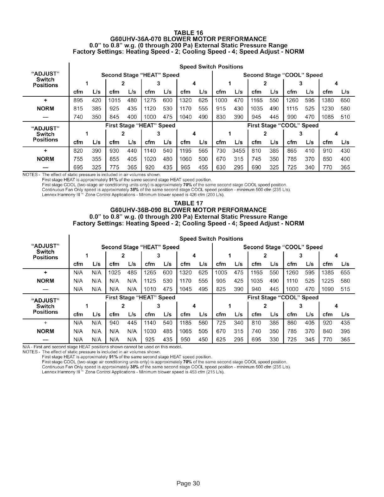
TABLE 16
G60UHV-36A-070 BLOWER MOTOR PERFORMANCE
0.0" to 0.8" w.g. (0 through 200 Pa) External Static Pressure Range
Factory Settings: Heating Speed - 2; Cooling Speed - 4; Speed Adjust - NORM
"ADJUST"
Switch
Positions
Speed Switch Positions
Second Stage "HEAT" Speed Second Stage "COOL" Speed
12341234
cfm L/s cfm L/s cfm L/s cfm L/s cfm L/s cfm L/s cfm L/s cfm L/s
+895 420 1015 480 1275 600 1320 625 1000 470 1165 550 1260 595 1380 650
NORM 815 385 925 435 1120 530 1170 555 915 430 1035 490 1115 525 1230 580
-- 740 350 845 400 1000 475 1040 490 830 390 945 445 990 470 1085 510
"ADJUST" First Stage "HEAT" Speed First Stage "COOL" Speed
Switch 1 2 3 4 1 2 3 4
Positions cfm L/s cfm L/s cfm L/s cfm L/s cfm L/s cfm L/s cfm L/s cfm L/s
+820 390 930 440 1140 540 1195 565 730 3455 810 385 865 410 910 430
NORM 755 355 855 405 1020 480 1060 500 670 315 745 350 785 370 850 400
i 695 325 775 365 920 435 965 455 630 295 690 325 725 340 770 365
NOTES - The effect of static pressure is included in air volumes shown.
First stage HEAT is approximately 91% of the same second stage HEAT speed position.
First stage COOL (two-stage air conditioning units only) is approximately 70% of the same second stage COOL speed position.
Continuous Fan Only speed is approximately 38% of the same second stage COOL speed position - minimum 500 cfm (235 L/s).
Lennox Harmony Ill" Zone Control Applications - Minimum blower speed is 426 cfm (200 L!s).
TABLE 17
G60UHV-36B-090 BLOWER MOTOR PERFORMANCE
0.0" to 0.8" w.g. (0 through 200 Pa) External Static Pressure Range
Factory Settings: Heating Speed - 2; Cooling Speed - 4; Speed Adjust - NORM
"ADJUST"
Switch
Positions
Speed Switch Positions
;econd Stage "HEAT" Speed Second Stage "COOL" Speed
12341234
cfm L/s cfm L/s cfm L/s cfm L/s cfm L/s cfm L/s cfm L/s cfm L/s
+ N/A N/A 1025 485 1265 600 1320 625 1005 475 1165 550 1260 595 1385 655
NORM N/A N/A N/A N/A 1125 530 1170 555 905 425 1035 490 1110 525 1225 580
i N/A N/A N/A N/A 1010 475 1045 495 825 390 940 445 1000 470 1090 515
"ADJUST" First Stage "HEAT" Speed First Stage "COOL" Speed
Switch 1 2 3 4 1 2 3 4
Positions cfm L/s cfm L/s cfm L/s cfm L/s cfm L/s cfm L/s cfm L/s cfm L/s
+ N/A N/A 940 445 1140 540 1185 560 725 340 810 385 860 405 920 435
NORM N/A N/A N/A N/A 1030 485 1065 505 670 315 740 350 785 370 840 395
-- N/A N/A N/A N/A 925 435 950 450 625 295 695 330 725 345 770 365
N/A - First and second stage HEAT positions shown cannot be used on this model.
NOTES - The effect of static pressure is included in air volumes shown.
First stage HEAT is approximately 91% of the same second stage HEAT speed position.
First stage COOL (two-stage air conditioning units only) is approximately 70% of the same second stage COOL speed position.
Continuous Fan Onty speed is approximately 38% of the same second stage COOL speed position - minimum 500 cfm (235 L/s).
Lennox Harmony Ill" Zone Controt Applications - Minimum blower speed is 453 cfm (215 L/s).
Page 30
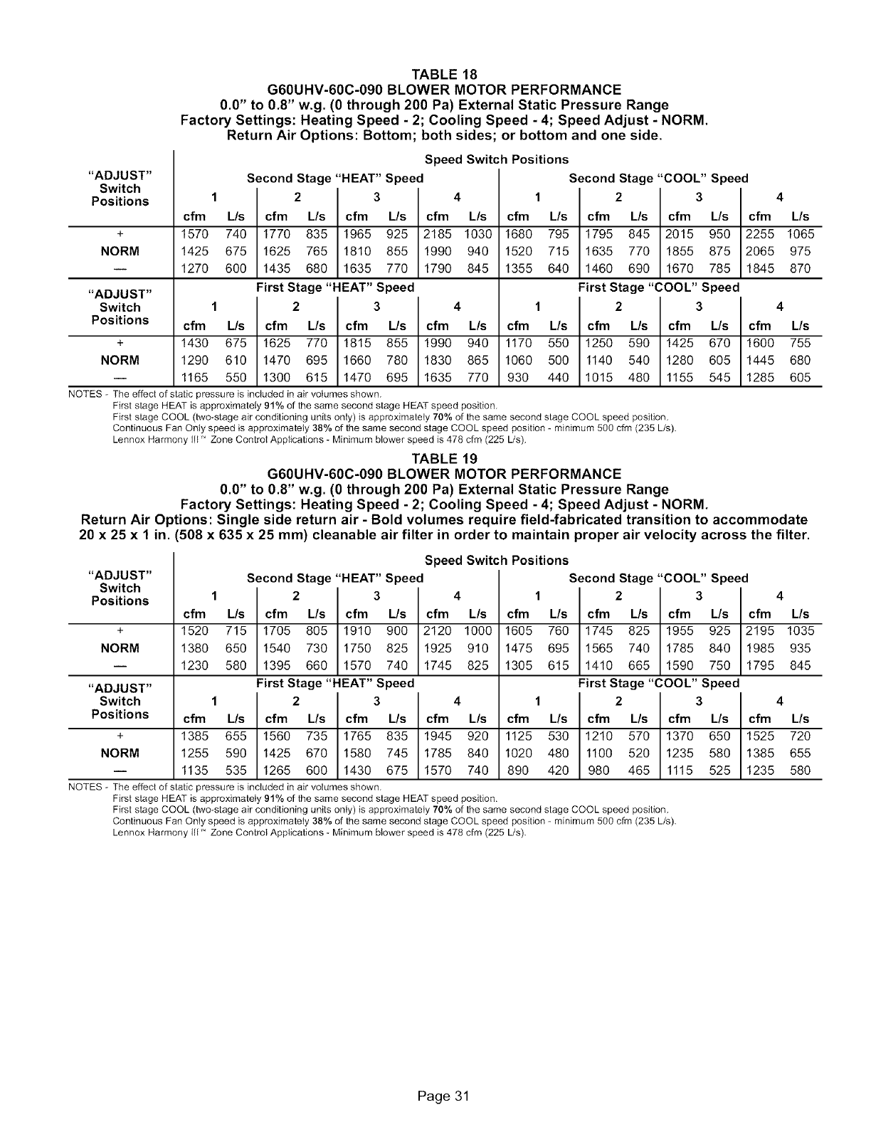
TABLE 18
G60UHV-60C-090 BLOWER MOTOR PERFORMANCE
0.0" to 0.8" w.g. (0 through 200 Pa) External Static Pressure Range
Factory Settings: Heating Speed - 2; Cooling Speed - 4; Speed Adjust - NORM.
Return Air Options: Bottom; both sides; or bottom and one side.
"ADJUST"
Switch
Positions
Speed Switch Positions
Second Stage "HEAT" Speed Second Stage "COOL" Speed
1 2 3 4 1 2 3 4
cfm L/s cfm L/s cfm L/s cfm L/s cfm L/s cfm L/s cfm L/s cfm L/s
+ 1570 740 1770 835 1965 925 2185 1030 1680 795 1795 845 2015 950 2255 1065
NORM 1425 675 1625 765 1810 855 1990 940 1520 715 1635 770 1855 875 2065 975
-- 1270 600 1435 680 1635 770 1790 845 1355 640 1460 690 1670 785 1845 870
"ADJUST" First Stage "HEAT" Speed First Stage "COOL" Speed
Switch 1 2 3 4 1 2 3 4
Positions cfm L/s cfm L/s cfm L/s cfm L/s cfm L/s cfm L/s cfm L/s cfm L/s
+ 1430 675 1625 770 1815 855 1990 940 1170 550 1250 590 1425 670 1600 755
NORM 1290 610 1470 695 1660 780 1830 865 1060 500 1140 540 1280 605 1445 680
-- 1165 550 1300 615 1470 695 1635 770 930 440 1015 480 1155 545 1285 605
NOTES - The effect of static pressure is included in air volumes shown.
First stage HEAT is approximately 91% of the same second stage HEAT speed position.
First stage COOL (two-stage air conditioning units only) is approximately 70% of the same second stage COOL speed position.
Continuous Fan Only speed is approximately 38% of the same second stage COOL speed position - minimum 500 cfm (235 L/s).
Lennox Harmony Ill ' Zone Control Applications - Minimum blower speed is 478 cfm (225 Us).
TABLE 19
G60UHV-60C-090 BLOWER MOTOR PERFORMANCE
0.0" to 0.8" w.g. (0 through 200 Pa) External Static Pressure Range
Factory Settings: Heating Speed - 2; Cooling Speed - 4; Speed Adjust - NORM.
Return Air Options: Single side return air - Bold volumes require field-fabricated transition to accommodate
20 x 25 x 1 in. (508 x 635 x 25 mm) cleanable air filter in order to maintain proper air velocity across the filter.
"ADJUST"
Switch
Positions
Speed Switch Positions
Second Stage "HEAT" Speed Second Stage "COOL" Speed
1 2 3 4 1 2 3 4
cfm L/s cfm L/s cfm L/s cfm L/s cfm L/s cfm L/s cfm L/s cfm L/s
+ 1520 715 1705 805 1910 900 2120 1000 1605 760 1745 825 1955 925 2195 1035
NORM 1380 650 1540 730 1750 825 1925 910 1475 695 1565 740 1785 840 1985 935
i 1230 580 1395 660 1570 740 1745 825 1305 615 1410 665 1590 750 1795 845
"ADJUST" First Stage "HEAT" Speed First Stage "COOL" Speed
Switch 1 2 3 4 1 2 3 4
Positions cfm L/s cfm L/s cfm L/s cfm L/s cfm L/s cfm L/s cfm L/s cfm L/s
+ 1385 655 1560 735 1765 835 1945 920 1125 530 1210 570 1370 650 1525 720
NORM 1255 590 1425 670 1580 745 1785 840 1020 480 1100 520 1235 580 1385 655
i 1135 535 1265 600 1430 675 1570 740 890 420 980 465 1115 525 1235 580
NOTES - The effect of static pressure is included in air volumes shown.
First stage HEAT is approximately 91% of the same second stage HEAT speed position.
First stage COOL (two-stage air conditioning units only) is approximately 70% of the same second stage COOL speed position.
Continuous Fan Only speed is approximately 38% of the same second stage COOL speed position - minimum 500 cfm (235 L/s).
Lennox Harmony Iit" Zone Control Applications - Minimum blower speed is 478 cfm (225 L/s).
Page 31
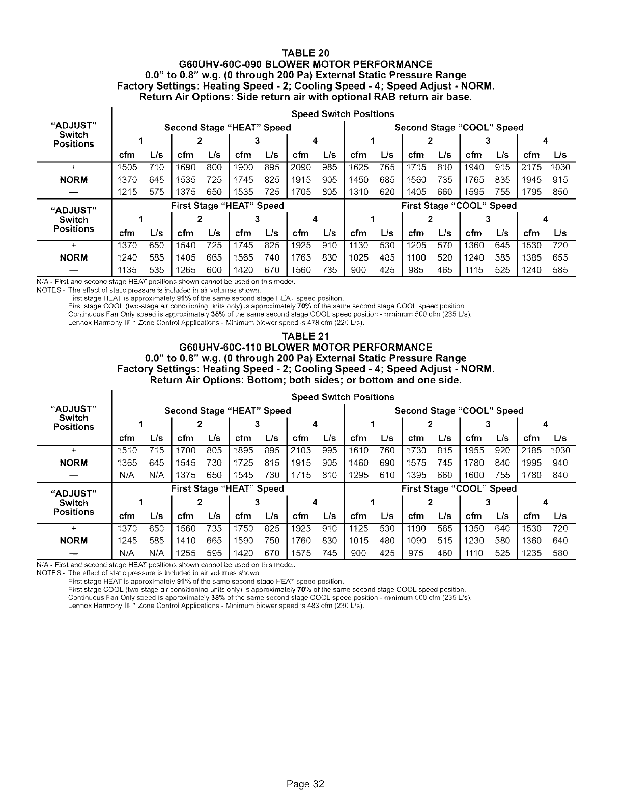
TABLE 20
G60UHV-60C-090 BLOWER MOTOR PERFORMANCE
0.0" to 0.8" w.g. (0 through 200 Pa) External Static Pressure Range
Factory Settings: Heating Speed - 2; Cooling Speed - 4; Speed Adjust - NORM.
Return Air Options: Side return air with optional RAB return air base.
"ADJUST"
Switch
Positions
Speed Switch Positions
Second Stage "HEAT" Speed Second Stage "COOL" Speed
12341234
cfm L/s cfm L/s cfm L/s cfm L/s cfm L/s cfm L/s cfm L/s cfm L/s
+ 1505 710 1690 800 1900 895 2090 985 1625 765 1715 810 1940 915 2175 1030
NORM 1370 645 1535 725 1745 825 1915 905 1450 685 1560 735 1765 835 1945 915
-- 1215 575 1375 650 1535 725 1705 805 1310 620 1405 660 1595 755 1795 850
"ADJUST" First Stage "HEAT" Speed First Stage "COOL" Speed
Switch 1 2 3 4 1 2 3 4
Positions cfm L/s cfm L/s cfm L/s cfm L/s cfm L/s cfm L/s cfm L/s cfm L/s
+ 1370 650 1540 725 1745 825 1925 910 1130 530 1205 570 1360 645 1530 720
NORM 1240 585 1405 665 1565 740 1765 830 1025 485 1100 520 1240 585 1385 655
-- 1135 535 1265 600 1420 670 1560 735 900 425 985 465 1115 525 1240 585
N/A - First and second stage HEAT positions shown cannot be used on this model.
NOTES - The effect of static pressure is included in air volumes shown.
First stage HEAT is approximately 91% of the same second stage HEAT speed position.
First stage COOL (two-stage air conditioning units only) is approximately 70% of the same second stage COOL speed position.
Continuous Fan Only speed is approximately 38% of the same second stage COOL speed position - minimum 500 cfm (235 Us).
Lennox Harmony Ill ' Zone Control Applications - Minimum blower speed is 478 cfm (225 Us).
TABLE 21
G60UHV-60C-110 BLOWER MOTOR PERFORMANCE
0.0" to 0.8" w.g. (0 through 200 Pa) External Static Pressure Range
Factory Settings: Heating Speed - 2; Cooling Speed - 4; Speed Adjust - NORM.
Return Air Options: Bottom; both sides; or bottom and one side.
"ADJUST"
Switch
Positions
Speed Switch Positions
Second Stage "HEAT" Speed Second Stage "COOL" Speed
12341234
cfm L/s cfm L/s cfm L/s cfm L/s cfm L/s cfm L/s cfm L/s cfm L/s
+ 1510 715 1700 805 1895 895 2105 995 1610 760 1730 815 1955 920 2185 1030
NORM 1365 645 1545 730 1725 815 1915 905 1460 690 1575 745 1780 840 1995 940
-- N/A N/A 1375 650 1545 730 1715 810 1295 610 1395 660 1600 755 1780 840
"ADJUST" First Stage "HEAT" Speed First Stage "COOL" Speed
Switch 1 2 3 4 1 2 3 4
Positions cfm L/s cfm L/s cfm L/s cfm L/s cfm L/s cfm L/s cfm L/s cfm L/s
+ 1370 650 1560 735 1750 825 1925 910 1125 530 1190 565 1350 640 1530 720
NORM 1245 585 1410 665 1590 750 1760 830 1015 480 1090 515 1230 580 1360 640
-- N/A N/A 1255 595 1420 670 1575 745 900 425 975 460 1110 525 1235 580
N/A - First and second stage HEAT positions shown cannot be used on this model.
NOTES - The effect of static pressure is included in air volumes shown.
First stage HEAT is approximately 91% of the same second stage HEAT speed position.
First stage COOL (two-stage air conditioning units only) is approximately 70% of the same second stage COOL speed position.
Continuous Fan Only speed is approximately 38% of the same second stage COOL speed position - minimum 500 cfm (235 Us).
Lennox Harmony Ill" Zone Controt Applications - Minimum blower speed is 483 cfm (230 L/s).
Page 32
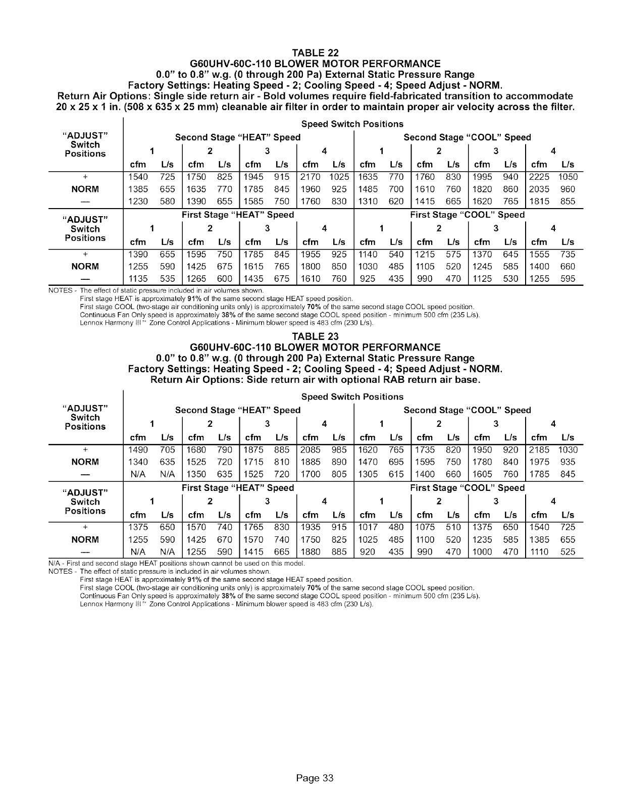
TABLE 22
G60UHV-60C-110 BLOWER MOTOR PERFORMANCE
0.0" to 0.8" w.g. (0 through 200 Pa) External Static Pressure Range
Factory Settings: Heating Speed - 2; Cooling Speed - 4; Speed Adjust - NORM.
Return Air O _tions: Single side return air - Bold volumes require field-fabricated transition to accommodate
20 x 25 x 1 in. 508 x 635 x 25 mm) cleanable air filter in order to maintain proper air velocity across the filter.
Speed Switch Positions
"ADJUST" Second Stage "HEAT" Speed Second Stage "COOL" Speed
Switch
Positions 1 2 3 4 1 2 3
cfm L/s cfm L/s cfm L/s cfm L/s cfm L/s cfm L/s cfm L/s
+ 1540 725 1750 825 1945 915 2170 1025 1635 770 1760 830 1995 940
NORM 1385 655 1635 770 1785 845 1960 925 1485 700 1610 760 1820 860
i 1230 580 1390 655 1585 750 1760 830 1310 620 1415 665 1620 765
"ADJUST" First Stage "HEAT" Speed First Stage "COOL" Speed
Switch 1 2 3 4 1 2 3 4
Positions cfm L/s cfm L/s cfm L/s cfm L/s cfm L/s cfm L/s cfm L/s cfm L/s
+ 1390 655 1595 750 1785 845 1955 925 1140 540 1215 575 1370 645 1555 735
NORM 1255 590 1425 675 1615 765 1800 850 1030 485 1105 520 1245 585 1400 660
i 1135 535 1265 600 1435 675 1610 760 925 435 990 470 1125 530 1255 595
NOTES - The effect of static pressure included in air volumes shown.
First stage HEAT is approximately 91% of the same second stage HEAT speed position.
First stage COOL (two-stage air conditioning units only) is approximately 70% of the same second stage COOL speed position.
Continuous Fan Only speed is approximately 38% of the same second stage COOL speed position - minimum 500 cfm (235 L/s).
Lennox Harmony Ill" Zone Control Applications - Minimum blower speed is 483 cfm (230 L/s).
TABLE 23
G60UHV-60C-110 BLOWER MOTOR PERFORMANCE
0.0" to 0.8" w.g. (0 through 200 Pa) External Static Pressure Range
Factory Settings: Heating Speed - 2; Cooling Speed - 4; Speed Adjust - NORM.
Return Air Options: Side return air with optional RAB return air base.
4
cfm L/s
2225 1050
2035 960
1815 855
"ADJUST"
Switch
Positions
Speed Switch Positions
Second Stage "HEAT" Speed Second Stage "COOL" Speed
1 2 3 4 1 2 3 4
cfm L/s cfm L/s cfm L/s cfm L/s cfm L/s cfm L/s cfm L/s cfm L/s
+ 1490 705 1680 790 1875 885 2085 985 1620 765 1735 820 1950 920 2185 1030
NORM 1340 635 1525 720 1715 810 1885 890 1470 695 1595 750 1780 840 1975 935
i N/A N/A 1350 635 1525 720 1700 805 1305 615 1400 660 1605 760 1785 845
"ADJUST" First Stage "HEAT" Speed First Stage "COOL" Speed
Switch 1 2 3 4 1 2 3 4
Positions cfm L/s cfm L/s cfm L/s cfm L/s cfm L/s cfm L/s cfm L/s cfm L/s
+ 1375 650 1570 740 1765 830 1935 915 1017 480 1075 510 1375 650 1540 725
NORM 1255 590 1425 870 1570 740 1750 825 1025 485 1100 520 1235 585 1385 855
-- N/A N/A 1255 590 1415 665 1880 885 920 435 990 470 1000 470 1110 525
N/A - First and second stage HEAT positions shown cannot be used on this model.
NOTES - The effect of static pressure is included in air volumes shown.
First stage HEAT is approximately 91% of the same second stage HEAT speed position.
First stage COOL (two-stage air conditioning units only) is approximately 70% of the same second stage COOL speed position.
Continuous Fan Only speed is approximately 38% of the same second stage COOL speed position - minimum 500 cfm (235 L/s).
Lennox Harmony Ill ' Zone Control Applications - Minimum blower speed is 483 cfm (230 L!s).
Page 33
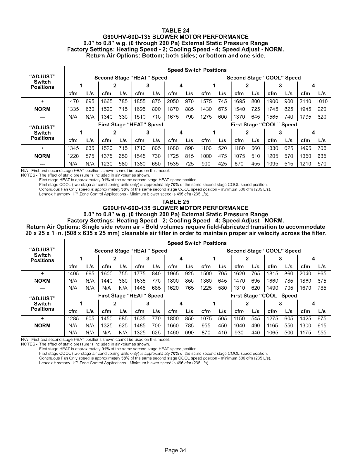
TABLE 24
G60UHV-60D-135 BLOWER MOTOR PERFORMANCE
0.0" to 0.8" w.g. (0 through 200 Pa) External Static Pressure Range
Factory Settings: Heating Speed - 2; Cooling Speed - 4; Speed Adjust - NORM.
Return Air Options: Bottom; both sides; or bottom and one side.
"ADJUST"
Switch
Positions
Speed Switch Positions
Second Stage "HEAT" Speed Second Stage "COOL" Speed
12341234
cfm L/s cfm L/s cfm L/s cfm L/s cfm L/s cfm L/s cfm L/s cfm L/s
+ 1470 695 1665 785 1855 875 2050 970 1575 745 1695 800 1900 900 2140 1010
NORM 1335 630 1520 715 1695 800 1870 885 1430 675 1540 725 1745 825 1945 920
i N/A N/A 1340 630 1510 710 1675 790 1275 600 1370 645 1565 740 1735 820
"ADJUST" First Stage "HEAT" Speed First Stage "COOL" Speed
Switch 1 2 3 4 1 2 3 4
Positions cfm L/s cfm L/s cfm L/s cfm L/s cfm L/s cfm L/s cfm L/s cfm L/s
+ 1345 635 1520 715 1710 805 1880 890 1100 520 1180 560 1330 625 1495 705
NORM 1220 575 1375 650 1545 730 1725 815 1000 475 1075 510 1205 570 1350 635
-- N/A N/A 1230 580 1380 650 1535 725 900 425 670 455 1095 515 1210 570
N/A - First and second stage HEAT positions shown cannot be used on this model.
NOTES - The effect of static pressure is included in air volumes shown.
First stage HEAT is approximately 91% of the same second stage HEAT speed position.
First stage COOL (two-stage air conditioning units only) is approximately 70% of the same second stage COOL speed position.
Continuous Fan Only speed is approximately 38% of the same second stage COOL speed position - minimum 500 cfm (235 Us).
Lennox Harmony Ill ' Zone Control Applications - Minimum blower speed is 495 cfm (235 Us).
TABLE 25
G60UHV-60D-135 BLOWER MOTOR PERFORMANCE
0.0" to 0.8" w.g. (0 through 200 Pa) External Static Pressure Range
Factory Settings: Heating Speed - 2; Cooling Speed - 4; Speed Adjust - NORM.
Return Air Options: Single side return air - Bold volumes require field-fabricated transition to accommodate
20 x 25 x 1 in. 508 x 635 x 25 mm) cleanable air filter in order to maintain proper air velocity across the filter.
"ADJUST"
Switch
Positions
Speed Switch Positions
Second Stage "HEAT" Speed Second Stage "COOL" Speed
1 2 3 4
cfm L/s cfm L/s cfm L/s cfm L/s
1500 705 1620 765 1815 860 2040 965
1360 645 1470 695 1660 785 1860 875
1225 580 1310 620 1490 705 1670 785
1234
cfm L/s cfm L/s cfm L/s cfm L/s
+ 1405 665 1600 755 1775 840 1965 925
NORM N/A N/A 1440 680 1635 770 1800 850
i N/A N/A N/A N/A 1445 685 1620 765
"ADJUST" First Stage "HEAT" Speed First Stage "COOL" Speed
Switch 1 2 3 4 1 2 3 4
Positions cfm L/s cfm L/s cfm L/s cfm L/s cfm L/s cfm L/s cfm L/s cfm L/s
+ 1285 605 1450 685 1635 770 1800 850 1075 505 1150 545 1275 605 1425 675
NORM N/A N/A 1325 625 1485 700 1660 785 955 450 1040 490 1165 550 1300 615
i N/A N/A N/A N/A 1325 625 1460 690 870 410 930 440 1065 500 1175 555
N/A - First and second stage HEAT positions shown cannot be used on this model.
NOTES - The effect of static pressure is included in air volumes shown.
First stage HEAT is approximately 91% of the same second stage HEAT speed position.
First stage COOL (two-stage air conditioning units only) is approximately 70% of the same second stage COOL speed position.
Continuous Fan Only speed is approximately 38% of the same second stage COOL speed position - minimum 500 cfm (235 Us).
Lennox Harmony Ill" Zone Control Applications - Minimum blower speed is 495 cfm (235 Us).
Page 34
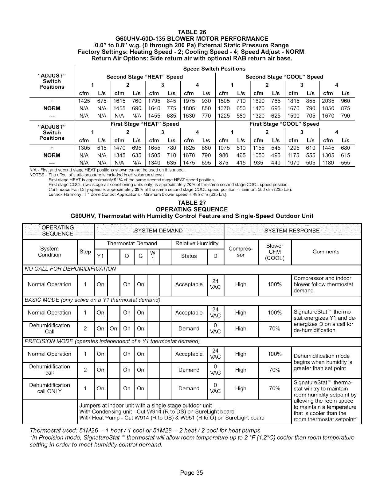
TABLE 26
G60UHV-60D-135 BLOWER MOTOR PERFORMANCE
0.0" to 0.8" w.g. (0 through 200 Pa) External Static Pressure Range
Factory Settings: Heating Speed - 2; Cooling Speed - 4; Speed Adjust - NORM.
Return Air Options: Side return air with optional RAB return air base.
"ADJUST"
Switch
Positions
Speed Switch Positions
Second Stage "HEAT" Speed Second Stage "COOL" Speed
1 2 3 4 1 2 3 4
cfm L/s cfm L/s cfm L/s cfm L/s cfm L/s cfm L/s cfm L/s cfm L/s
+ 1425 675 1615 760 1795 845 1975 930 1505 710 1620 765 1815 855 2035 960
NORM N/A N/A 1455 690 1640 775 1805 850 1370 650 1470 695 1670 790 1850 875
-- N/A N/A N/A N/A 1455 685 1630 770 1225 580 1320 625 1500 705 1670 790
"ADJUST" First Stage "HEAT" Speed First Stage "COOL" Speed
Switch 1 2 3 4 1 2 3 4
Positions cfm L/s cfm L/s cfm L/s cfm L/s cfm L/s cfm L/s cfm L/s cfm L/s
+ 1305 615 1470 695 1655 780 1825 860 1075 510 1155 545 1295 610 1445 680
NORM N/A N/A 1345 635 1505 710 1670 790 980 465 1050 495 1175 555 1305 615
-- N/A N/A N/A N/A 1340 635 1475 695 875 415 935 440 1070 505 1180 555
N/A - First and second stage HEAT positions shown cannot be used on this model.
NOTES - The effect of static pressure is included in air volumes shown.
First stage HEAT is approximately 91% of the same second stage HEAT speed position.
First stage COOL (two-stage air conditioning units only) is approximately 70% of the same second stage COOL speed position.
Continuous Fan Only speed is approximately 38% of the same second stage COOL speed position - minimum 500 cfm (235 L/s).
Lennox Harmony Ill 'Zone Control Applications - Minimum blower speed is 495 cfm (235 L/s).
TABLE 27
OPERATING SEQUENCE
G60UHV, Thermostat with Humidity Control Feature and Single-Speed Outdoor Unit
OPERATING t 't .......
•S¥S EM DEMAND S¥S EM RESPONSE
SEQUENCE .
Thermostat Demand Relative Humidity
System Step I III
Condition Y1 O G W
1 Status D
NO CALL FOR DEHUMIDIFICATION
Normal Operation 1 On On On
BASIC MODE (only active on a Y1 thermostat demand)
Normal Operation 1 On On On
Dehumidification 2 On On On On
Call
Compres-
sor
24
Acceptable VAC High
24
Acceptable VAC High
0
Demand VAC High
Blower
CFM
(COOL)
lOO%
lOO%
70%
Comments
Compressor and indoor
blower follow thermostat
demand
SignatureStat T" thermo-
stat energizes Y1 and de-
energizes D on a call for
de-humidification
PRECISION MODE (operates ind_ oendent of a Y1 thermostat demand)
Normal Operation
Dehumidification
call
Dehumidification
call ONLY
24
1 On On On Acceptable VAC High
0
2 On On On Demand VAC High
0
1 On On On Demand VAC High
Jumpers at indoor unit with a single stage outdoor unit
With Condensing unit - Cut W914 (R to DS) on SureLight board
With Heat Pump - Cut W914 (R to DS) & W951 (R to O) on SureLight board
100%
70%
70%
Dehumidification mode
begins when humidity is
greater than set point
SignatureStat T`'thermo-
stat will try to maintain
room humidity setpoint by
allowing the room space
to maintain a temperature
that is cooler than the
room thermostat setpoint*
Thermostat used: 51M26 -- 1 heat/1 cool or 51M28 -- 2 heat/2 cool for heat pumps
*In Precision mode, SignatureStat "thermostat will allow room temperature up to 2 °F (1.2°C) cooler than room temperature
setting in order to meet humidity control demand.
Page 35
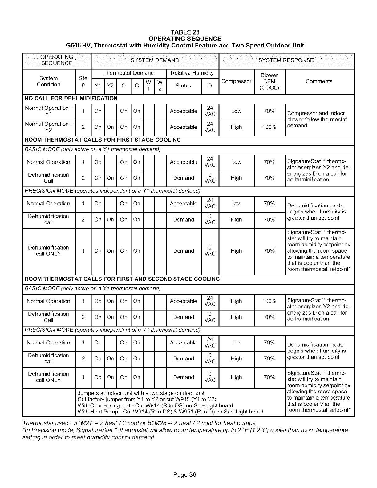
TABLE 28
OPERATING SEQUENCE
G60UHV, Thermostat with Humidity Control Feature and Two-Speed Outdoor Unit
OPERATING _-I T .......
SEQUENCE I SYS EM DEMAND S¥S EM RESPONSE
Thermostat Demand Relative Humidity
System Ste
Condition P ww I
1 Status D
NO CALL FOR DEHUMIDIFICATION
Compressor
Blower
CFM
(COOL)
Comments
Normal Operation - 24
Y1 1 On On On Acceptable VAC
Normal Operation - 24
Y2 2 On On On On Acceptable VAC
Low
High
70%
100%
Compressor and indoor
blower follow thermostat
demand
ROOM THERMOSTAT CALLS FOR FIRST STAGE COl)LING
BASIC MODE (only active on a Y1 thermostat demand)
Normal Operation 1 On On On
Dehumidification
Call 2 On On On On
24
Acceptable VAC
0
Demand VAC
Low
High
70%
70%
SignatureStat T" thermo-
stat energizes Y2 and de-
energizes D on a call for
de-humidification
PRECISION MODE (operates independent of a Y1 thermostat demand)
24
Normal Operation 1 On On On Acceptable VAC
Dehumidification 0
2 On On On On Demand
call VAC
Dehumidification 0
call ONLY 1 On On On On Demand VAC
ROOM THERMOSTAT CALLS FOR FIRST AND SECOND STAGE COOLING
BASIC MODE (only active on a Y1 thermostat demand)
24
Normal Operation 1 On On On On Acceptable VAC
Dehumidification 0
2 On On On On Demand
Call VAC
Low
High
High
High
High
70%
70%
70%
10o%
7o%
Dehumidification mode
begins when humidity is
greater than set point
SignatureStat T_ thermo-
stat will try to maintain
room humidity setpoint by
allowing the room space
to maintain a temperature
that is cooler than the
room thermostat setpoint*
SignatureStat T" thermo-
stat energizes Y2 and de-
energizes D on a call for
de-humidification
PRECISION MODE (operates independent of a Y1 thermostat demand)
Normal Operation 1 On On On Acceptable
Dehumidification 2 On On On On Demand
call
Dehumidification
call ONLY 1 On On On On Demand
24
VAC Low
0
VAC High
0
VAC High
70%
70%
70%
Jumpers at indoor unit with a two stage outdoor unit
Cut factory jumper from Y1 to Y2 or cut W915 (Y1 to Y2)
With Condensing unit - Cut W914 (R to DS) on SureLight board
With Heat Pump - Cut W914 (R to DS) & W951 (R to O) on SureLight board
Dehumidification mode
begins when humidity is
greater than set point
SignatureStat T_ thermo-
stat will try to maintain
room humidity setpoint by
allowing the room space
to maintain a temperature
that is cooler than the
room thermostat setpoint*
Thermostat used: 51M27 -- 2 heat/2 cool or 51M28 -- 2 heat/2 cool for heat pumps
*In Precision mode, SignatureStat "thermostat will allow room temperature up to 2 °F (1.2°C) coolerthan room temperature
setting in order to meet humidity control demand.
Page 36
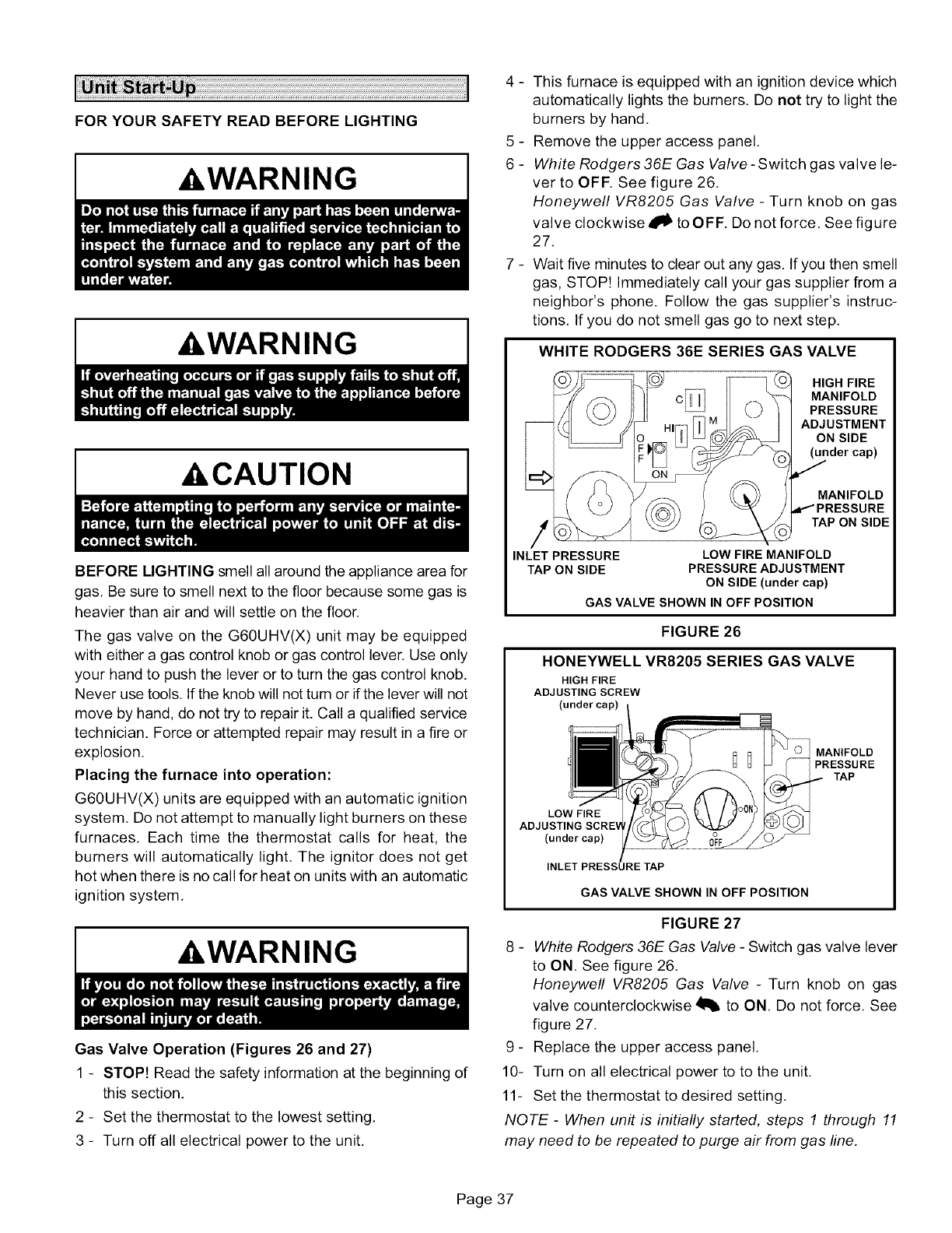
FOR YOUR SAFETY READ BEFORE LIGHTING
AWARNING
AWARNING
ACAUTION
BEFORE LIGHTING smell all around the appliance area for
gas, Be sure to smell next to the floor because some gas is
heavier than air and will settle on the floor.
The gas valve on the G60UHV(X) unit may be equipped
with either a gas control knob or gas control lever. Use only
your hand to push the lever or to turn the gas control knob.
Never use tools, If the knob will not tum or if the lever will not
move by hand, do not try to repair it. Call a qualified service
technician. Force or attempted repair may result in a fire or
explosion.
Placing the furnace into operation:
G60UHV(X) units are equipped with an automatic ignition
system. Do not attempt to manually light burners on these
furnaces, Each time the thermostat calls for heat, the
burners will automatically light, The ignitor does not get
hot when there is no call for heat on units with an automatic
ignition system,
AWARNING
Gas Valve Operation (Figures 26 and 27)
1 - STOP! Read the safety information at the beginning of
this section.
2 - Set the thermostat to the lowest setting,
3 - Turn off all electrical power to the unit,
4 - This furnace is equipped with an ignition device which
automatically lights the burners. Do not try to light the
burners by hand.
5 - Remove the upper access panel.
6 - White Rodgers 36E Gas Valve - Switch gas valve le-
ver to OFF. See figure 26.
Honeywell VR8205 Gas Valve - Turn knob on gas
valve clockwise _ to OFF. Do not force. See figure
27.
7 - Wait five minutes to clear out any gas. If you then smell
gas, STOP! Immediately call your gas supplier from a
neighbor's phone. Follow the gas supplier's instruc-
tions. If you do not smell gas go to next step.
WHITE RODGERS 36E SERIES GAS VALVE
HIGH FIRE
MANIFOLD
PRESSURE
ADJUSTMENT
ON SIDE
(under cap)
MANIFOLD
TAP ON SIDE
INLET PRESSURE LOW FIRE MANIFOLD
TAP ON SIDE PRESSURE ADJUSTMENT
ON SIDE (under cap)
GAS VALVE SHOWN IN OFF POSITION
FIGURE 26
HONEYWELL VR8205 SERIES GAS VALVE
HIGH FIRE
ADJUSTING SCREW
(under cap)
MANIFOLD
PRESSURE
TAP
LOW FIRE
(under cap)
INLET PRESSI _E TAP
GAS VALVE SHOWN IN OFF POSITION
FIGURE 27
8 - White Rodgers 36E Gas Valve - Switch gas valve lever
to ON. See figure 26,
Honeywell VR8205 Gas Valve - Turn knob on gas
valve counterclockwise 41_ to ON. Do not force, See
figure 27,
9 - Replace the upper access panel,
10- Turn on all electrical power to to the unit,
11- Set the thermostat to desired setting,
NOTE -When unit is initially started, steps 1 through 11
may need to be repeated to purge air from gas line,
Page 37
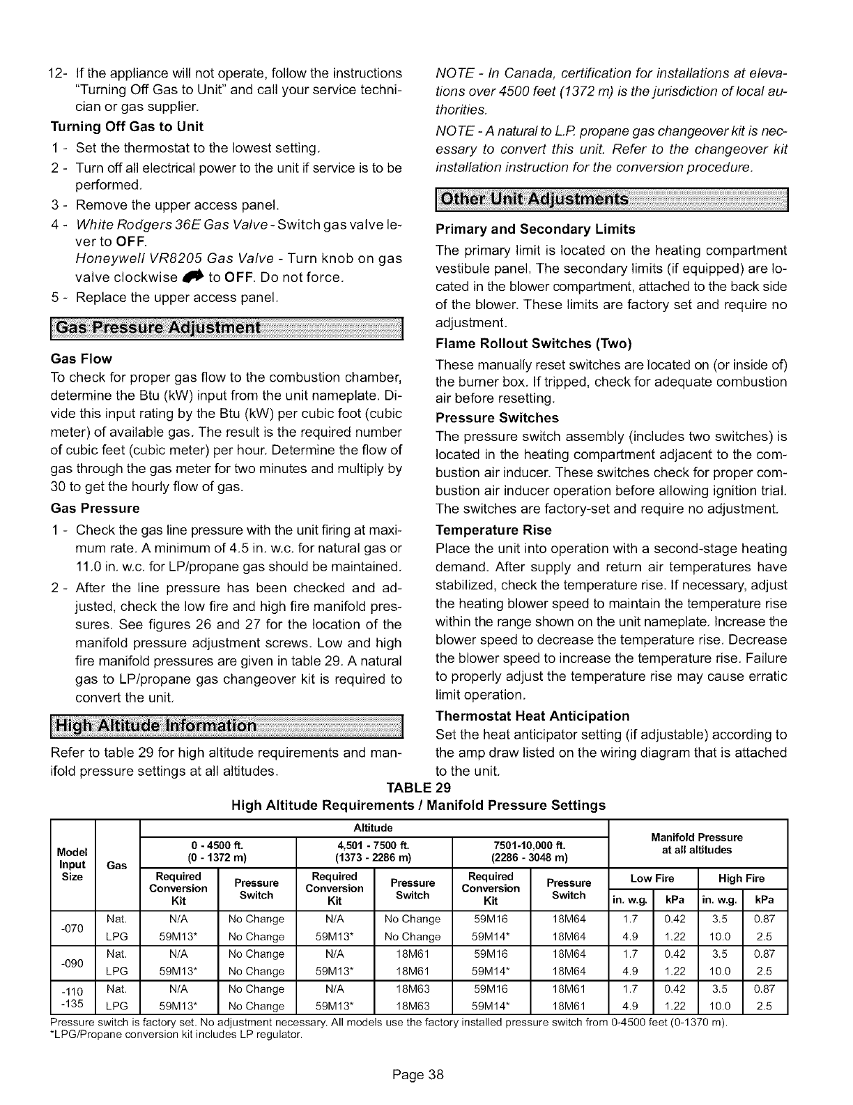
12- Iftheappliancewillnotoperate,followtheinstructions
"TurningOffGastoUnit"andcallyourservicetechni-
cianor gas supplier.
Turning Off Gas to Unit
1 - Set the thermostat to the lowest setting,
2 - Turn off all electrical power to the unit if service is to be
performed,
3 - Remove the upper access panel.
4 - White Rodgers 36E Gas Valve- Switch gas valve le-
verto OFF.
Honeywell VR8205 Gas Valve - Turn knob on gas
valve clockwise _ll to OFF, Do not force,
5 - Replace the upper access panel,
Gas Flow
To check for proper gas flow to the combustion chamber,
determine the Btu (kW) input from the unit nameplate, Di-
vide this input rating by the Btu (kW) per cubic foot (cubic
meter) of available gas, The result is the required number
of cubic feet (cubic meter) per hour. Determine the flow of
gas through the gas meter for two minutes and multiply by
30 to get the hourly flow of gas,
Gas Pressure
1 - Check the gas line pressure with the unit firing at maxi-
mum rate, A minimum of 4,5 in, w,c, for natural gas or
11,0 in, w,c, for LP/propane gas should be maintained,
2- After the line pressure has been checked and ad-
justed, check the low fire and high fire manifold pres-
sures, See figures 26 and 27 for the location of the
manifold pressure adjustment screws. Low and high
fire manifold pressures are given in table 29, A natural
gas to LP/propane gas changeover kit is required to
convert the unit,
Refer to table 29 for high altitude requirements and man-
ifold pressure settings at all altitudes.
NOTE -In Canada, certification for installations at eleva-
tions over 4500 feet (1372 m) is the jurisdiction of local au-
thorities.
NOTE -A natural to L.P.propane gas changeover kit is nec-
essary to convert this unit. Refer to the changeover kit
installation instruction for the conversion procedure.
Primary and Secondary Limits
The primary limit is located on the heating compartment
vestibule panel. The secondary limits (if equipped) are lo-
cated in the blower compartment, attached to the back side
of the blower, These limits are factory set and require no
adjustment.
Flame Rollout Switches (Two)
These manually reset switches are located on (or inside of)
the burner box, If tripped, check for adequate combustion
air before resetting.
Pressure Switches
The pressure switch assembly (includes two switches) is
located in the heating compartment adjacent to the com-
bustion air inducer. These switches check for proper com-
bustion air inducer operation before allowing ignition trial,
The switches are factory-set and require no adjustment,
Temperature Rise
Place the unit into operation with a second-stage heating
demand. After supply and return air temperatures have
stabilized, check the temperature rise. If necessary, adjust
the heating blower speed to maintain the temperature rise
within the range shown on the unit nameplate, Increase the
blower speed to decrease the temperature rise, Decrease
the blower speed to increase the temperature rise. Failure
to properly adjust the temperature rise may cause erratic
limit operation,
Thermostat Heat Anticipation
Set the heat anticipator setting (if adjustable) according to
the amp draw listed on the wiring diagram that is attached
to the unit,
TABLE 29
High Altitude Requirements /Manifold Pressure Settings
Model
Input
Size Gas
0 - 4500 ft.
(0 - 1372 m)
Required
Conversion Pressure
Kit Switch
Altitude
4,501 -7500 ft.
(1373 -2286 m)
Required
Conversion Pressure
Kit Switch
7501-10,000 ft.
(2286 - 3048 m)
Required
Conversion Pressure
Kit Switch
Manifold Pressure
at all altitudes
in. w.g. kPa in. w.g.
Nat. N/A No Change N/A No Change 59M16 18M64 1.7 0.42 3.5
-070 LPG 59M13" No Change 59M13" No Change 59M14" 18M64 4.9 1.22 10.0
Nat, N/A No Change N/A 18M61 59M16 18M64 1.7 0.42 3.5
-090 LPG 59M13" No Change 59M13" 18M61 59M14" 18M64 4.9 1.22 10.0
-110 Nat. N/A No Change N/A 18M63 59M16 18M61 1.7 0.42 3.5
-135 LPG 59M13" No Change 59M13" 18M63 59M14" 18M61 4.9 1.22 10.0
Low Fire High Fire
kPa
0.87
2.5
0.87
2.5
0.87
2.5
Pressure switch is factory set. No adjustment necessary. All models use the factory installed pressure switch from 0-4500 feet (0-1370 m).
*LPG/Propane conversion kit includes LP regulator.
Page 38
Electrical
1- Checkallwiringforlooseconnections.
2 - Checkforthecorrectvoltageat thefurnace(furnace
operating).
3 - Checkamp-drawontheblowermotor.
MotorNameplate Actual
NOTE -Do not secure the electrical conduit directly to the
air ducts or structure.
Electronic Ignition
The two-stage, variable speed integrated control used in
G60UHV units has an added feature of an internal Watch-
guard control, The feature serves as an automatic reset de-
vice for ignition control lockout caused by ignition failure.
This type of lockout is usually due to low gas line pressure,
After one hour of continuous thermostat demand for heat,
the Watchguard will break and remake thermostat demand
to the furnace and automatically reset the control to begin
the ignition sequence,
Flue And Chimney
1 - Check flue pipe, chimney and all connections for tight-
ness and to make sure there is no blockage,
2 - Check unit for proper draft.
3 - Is pressure switch closed? Obstructed flue will cause
unit to shut off at pressure switch. Check flue and outlet
for blockages.
4 - Reset manual flame rollout switches on burner box,
Failure To Operate
If the unit fails to operate, check the following:
1 - Is the thermostat calling for heat?
2 - Are access panels securely in place?
3 - Is the main disconnect switch closed?
4 - Is there a blown fuse or tripped circuit breaker?
5 - Is the filter dirty or plugged? Dirty or plugged filters will
cause the limit control to shut the unit off.
6 - Is gas turned on at the meter?
7 - Is the manual main shut-off valve open?
8 - Is the internal manual shut-off valve open?
9 - Is the unit ignition system in lock out? Ifthe unit locks out
again, call the service technician to inspect the unit for
blockages.
NOTE -The control board thermostat selection DIP switch is
factory-set in the "TWO-STAGE" position.
Applications Using a Two-Stage Thermostat
A - Heating Sequence -- Control Board Thermostat
Selection DIP Switch in "Two-Stage" Position (Factory
Setting)
1 - On a call for heat, thermostat first-stage contacts close
sending a signal to the integrated control. The inte-
grated control runs a self-diagnostic program and
checks high temperature limit switches for normally
closed contacts and pressure switches for normally
open contacts.The combustion air inducer is ener-
gized at low speed and the 120 VAC humidifier termi-
nal is energized.
2 - Once the control receives a signal that the low pres-
sure switch has closed, the combustion air inducer be-
gins a 15-second pre-purge in low speed.
3 - After the pre-purge is complete, a 20-second initial ig-
nitor warm-up period begins. The combustion air in-
ducer continues to operate at low speed.
4 - After the 20-second warm-up period has ended, the gas
valve is energized on low fire (first stage) and ignition oc-
curs, At the same time, the control module sends a sig-
nal to begin an indoor blower 45-second ON-delay.
When the delay ends, the indoor blower motor is ener-
gized on the low fire heating speed and the 24V hu-
midifier terminal is energized. The furnace will contin-
ue this operation as long as the thermostat has a
first-stage heating demand,
5 - If second-stage heat is required, the thermostat sec-
ond-stage heat contacts close and send a signal to the
integrated control. The integrated control initiates a
30-second second-stage recognition delay.
6 - At the end of the recognition delay, the integrated con-
trol energizes the combustion air inducer at high
speed. The control also checks the high fire (second
stage) pressure switch to make sure it is closed.The
high fire (second stage) gas valve is energized and the
indoor blower motor is energized for operation at the
high fire heating speed.
7 - When the demand for high fire (second stage) heat is
satisfied, thecombustion air inducer is switched to the
low-fire heating speed and the high-fire (second
stage) gas valve is de-energized. The low-fire (first
stage) gas valve continues operation. The indoor
blower motor is switched to the low-fire heating speed.
8 - When the thermostat demand for low-fire (first stage)
heat is satisfied, the gas valve is de-energized and the
field-selected indoor blower off delay begins. The
combustion air inducer begins a 5-second post-purge
period.
9 - When the combustion air post-purge period is com-
plete, the inducer and humidifier terminals are de-en-
ergized. The indoor blower is de-energized at the end
of the off delay,
Applications Using A Single-Stage Thermostat
B - Heating Sequence -- Control Board Thermostat
Selection DIP Switch in "Single-Stage" Position
NOTE -In these applications, two-stage heat will be initi-
ated by the integrated control if heating demand has not
been satisfied after the field adjustable period (10 or 15
minutes).
1 - On a call for heat, thermostat first-stage contacts close
sending a signal to the integrated control. The inte-
grated control runs a self-diagnostic program and
checks high temperature limit switches for normally
closed contacts and pressure switches for normally
open contacts.The combustion air inducer is ener-
gized at low speed and the 120 VAC humidifier termi-
nal is energized,
2 - Once the control receives a signal that the low pres-
sure switch has closed, the combustion air inducer be-
gins a 15-second pre-purge in low speed,
3 - After the pre-purge is complete, a 20-second initial ig-
nitor warm-up period begins. The combustion air in-
ducer continues to operate at low speed.
Page 39
4 - Afterthe20-secondwarm-upperiodhasended,thegas
valveisenergizedonlowfire(firststage)andignitionoc-
curs.Atthesametime,thecontrolmodulesendsa sig-
nalto beginan indoorblower45-secondON-delay.
Whenthedelayends,theindoorblowermotorisener-
gizedonthelowfireheatingspeedandthe24Vhu-
midifierterminalisenergized.Theintegratedcontrol
alsoinitiatesa second-stageondelay(factory-setat
10minutes;adjustableto 15minutes).
5- Iftheheatingdemandcontinuesbeyondthesecond-
stageondelay,theintegratedcontrolenergizesthe
combustionairinducerathighspeed.Thecontrolalso
checksthehighfire(secondstage)pressureswitchto
makesureit isclosed.Thehighfire(secondstage)gas
valveisenergizedandtheindoorblowermotorisen-
ergizedforoperationatthehighfireheatingspeed.
6 - Whenthethermostatheatingdemandissatisfied,the-
combustionairinducerbeginsa 5-secondlowspeed
post-purge.Thefield-selectedindoorbloweroffdelay
begins.Theindoorbloweroperatesat the low-fire
heatingspeed.
7- Whenthecombustionairpost-purgeperiodis com-
plete,theinducerandhumidifierterminalsarede-en-
ergized.Theindoorblowerisde-energizedattheend
oftheoffdelay.
............................................................................................................................................................................................................................................
AWARNING
ACAUTION
At the beginning of each heating season, a qualified techni-
cian should check the system as follows:
Blower
Check the blower wheel for debris and clean if necessary.
The blower motors are prelubricated for extended bearing
life. No further lubrication is needed.
AWARNING
Filters
All G60UHV(X) filters are installed external to the unit. Fil-
ters should be inspected monthly, Clean or replace the fil-
ters when necessary to ensure that the furnace operates
properly. Replacement filters must be rated for high veloc-
ity airflow, Table 1 lists recommended filter sizes,
Flue And Chimney
Check the flue pipe, chimney and all connections for tight-
ness and to make sure there is no blockage,
Electrical
1 - Check all wiring for loose connections.
2 - Check for the correct voltage at the furnace (furnace
operating),
3 - Check amp-draw on the blower motor.
Motor Nameplate Actual
Cleaning the Heat Exchanger and Burners
NOTE -Use papers or protective covering in front of the fur-
nace during cleaning.
Cleaning the heat exchanger requires a steel spring
"snake," a reversible drill and a vacuum cleaner, The steel
spring snake may be constructed by purchasing a 4 ft, long
by 1/4 inch diameter steel wire cable and a 1/4 inch diame-
ter wire brush, These items are available at a hardware
store. Insert wire end of brush into the open end of the
spring cable. Crimp the cable around the brush so that the
brush is secured and will not come off during cleaning, At-
tach the other end of the cable to the reversible drill to com-
plete the tool for cleaning the heat exchanger.
1 - Turn off both electrical and gas power supplies to fur-
nace.
2 - Remove flue pipe and top cap from the unit. Label the
pressure switch wires, then disconnect them.
3 - Remove the four screws that secure the combustion air
inducer. Carefully remove the combustion air inducer to
avoid damaging blower gasket. If gasket is damaged, it
must be replaced to prevent leakage. See figure 1.
4 - Remove the collector box located behind the combus-
tion air inducer. Be careful with the collector box gas-
ket. If the gasket is damaged, it must be replaced to
prevent leakage.
5 - Label the wires from gas valve and rollout switches,
then disconnect them.
6 - Remove the four screws securing the burner box cover
and remove the cover.
7 - Disconnect gas supply piping. Remove six screws se-
curing the burner box /manifold assembly to the vesti-
bule panel and remove the assembly from the unit.
Take care not to damage the gasket.
8 - NOx units only - Remove the three screws that attach
the NOx insert to the corbel at the entrance to each
heat exchanger section. Carefully remove the NOx in-
sert from each section. See figure 29.
9 - Insert the brush end of cable snake into the top of one
of the heat exchanger openings, Do not force the
cable into the heat exchanger. Insert the cable and
operate the drill on slow speed, Move the cable in and
out of the heat exchanger section three or four times or
until sufficient cleaning is accomplished. Reverse drill
and slowly work the cable out of opening,
Page 40
G60UHV(X) BURNER & HEAT EXCHANGER REMOVAL
HEATEXCHANGER
GASKET
BOX
ASSEMBLY
GAS VALVE
ASSEMBLY
FIGURE 28
NOxlNSERTS
(X modelsonly)
/
FIGURE 29
10- Repeat procedure for each heat exchanger section.
11- After each of the top heat exchanger sections has been
cleaned, insert the brush end of the cable snake into
the bottom openings of each of the heat exchanger
sections and clean as described in step 8.
12- Remove the cable from the heat exchanger. Use a vac-
uum cleaner to remove debris knocked loose during
cleaning.
13- Attach the exhaust end (positive pressure) of the vacu-
um cleaner to the top of the heat exchanger section.
Any loose debris will be forced to the bottom of the heat
exchanger section. Vacuum debris from bottom open-
ings.
14- Replace collector box and combustion air inducer.
Check gaskets for damage. Damaged gaskets must be
replaced to avoid heat exchanger leaks. Replace all
screws to the collector box and combustion air inducer.
Failure to replace all screws may cause leaks.
15- To clean the burner, run a vacuum cleaner with a soft
brush attachment over the face of burners. Visually in-
spect inside the burners and crossovers for any blockage
caused by foreign matter. Remove any blockage.
16- NOx units only - Reattach the NOx inserts to the cor-
bels at the entrance to each heat exchanger opening.
See figure 29.
17- Re-install gasket and burner box /manifold assembly
onto the vestibule panel. Replace burner box cover
and re-secure using screws.
NOTE -Gasket must be replaced if it was damaged
during disassembly.
18- Reconnect wires to pressure switch, roll-out switches,
gas valve and combustion air inducer. Refer to unit wir-
ing diagram.
19- Re-install top cap and re-secure vent pipe to combus-
tion air inducer outlet.
20- Reconnect gas supply piping.
21- Turn on power and gas supply to unit.
22- Set thermostat and check for proper operation.
23- Check all piping connections, factory and field, for gas
leaks. Use a leak detecting solution or other preferred
means,
CAUTION
24- Ira leak is detected, shut gas and electricity offand
repair leak.
25- Repeat steps 23 and 24 until no leaks are detected.
26- Replace front access panel.
Page 41
ThefollowingrepairpartsareavailablethroughindependentLennoxdealers.Whenorderingparts,includethecomplete
furnacemodelnumberlistedontheCSAInternationalnameplate-- Example:G60UHV(X)-36A-070-7.
CabinetParts
Upperaccesspanel
Blowerpanel
Topcap
ControlPanelParts
Transformer
Two-stage,variablespeedintegratedcontrolboard
Doorinterlockswitch
Circuitbreaker
BlowerParts
Blowerwheel
Blowerhousing
Motor
Motorelectronics
Powerchoke(1hponly)
Motormountingframe
Motorcapacitor
Blowerhousingcutoffplate
HeatingParts
FlameSensor
Heatexchangerassembly
Gasmanifold
Two-speedcombustionairinducer
Two-stagegasvalve
Mainburnercluster
Mainburnerorifices
Pressureswitch
Ignitor
Primarylimitcontrol
Flamerolloutswitch
Secondarylimit
Page42
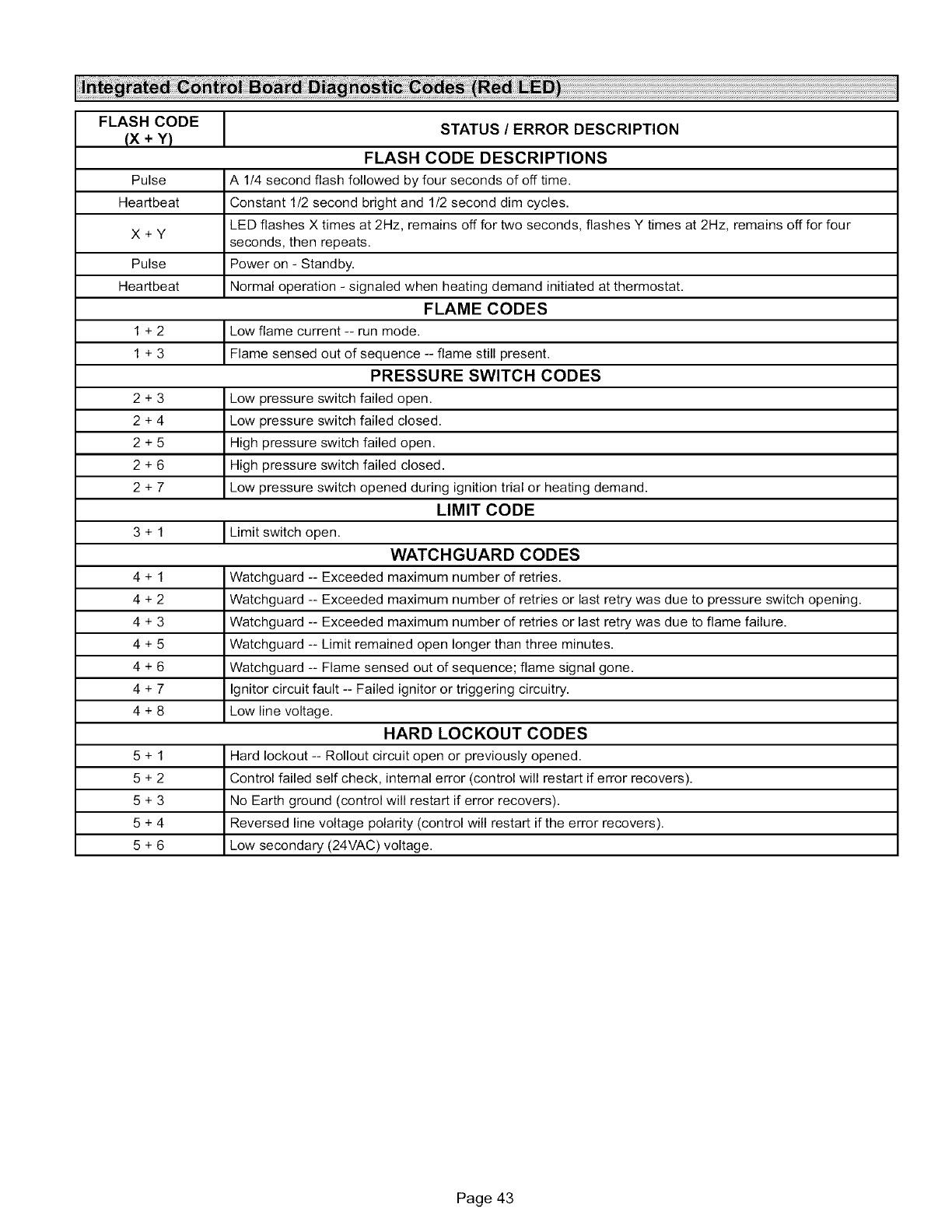
FLASH CODE
(x. Y)
Pulse
Heartbeat
X+Y
Pulse
Heartbeat
1+2
1+3
2+3
2+4
2+5
2+6
2+7
3+1
4+1
4+2
4+3
4+5
4+6
4+7
4+8
5+1
5+2
5+3
5+4
5+6
ISTATUS /ERROR DESCRIPTION
FLASH CODE DESCRIPTIONS
A 114 second flash followed by four seconds of off time.
Constant 1/2 second bright and 1/2 second dim cycles.
LED flashes X times at 2Hz, remains off for two seconds, flashes Y times at 2Hz, remains off for four
seconds, then repeats.
Power on - Standby.
Normal operation - signaled when heating demand initiated at thermostat.
FLAME CODES
Low flame current -- run mode.
Flame sensed out of sequence -- flame still present.
PRESSURE SWITCH CODES
Low pressure switch failed open.
Low pressure switch failed closed.
High pressure switch failed open.
High pressure switch failed closed.
Low pressure switch opened during ignition trial or heating demand.
LIMIT CODE
Limit switch open.
WATCHGUARD CODES
Watchguard -- Exceeded maximum number of retries.
Watchguard -- Exceeded maximum number of retries or last retry was due to pressure switch opening.
Watchguard -- Exceeded maximum number of retries or last retry was due to flame failure.
Watchguard -- Limit remained open longer than three minutes.
Watchguard -- Flame sensed out of sequence; flame signal gone.
Ignitor circuit fault -- Failed ignitor or triggering circuitry.
Low line voltage.
HARD LOCKOUT CODES
Hard lockout -- Rollout circuit open or previously opened.
Control failed self check, internal error (control will restart if error recovers).
No Earth ground (control will restart if error recovers).
Reversed line voltage polarity (control will restart if the error recovers).
Low secondary (24VAC) voltage.
Page 43
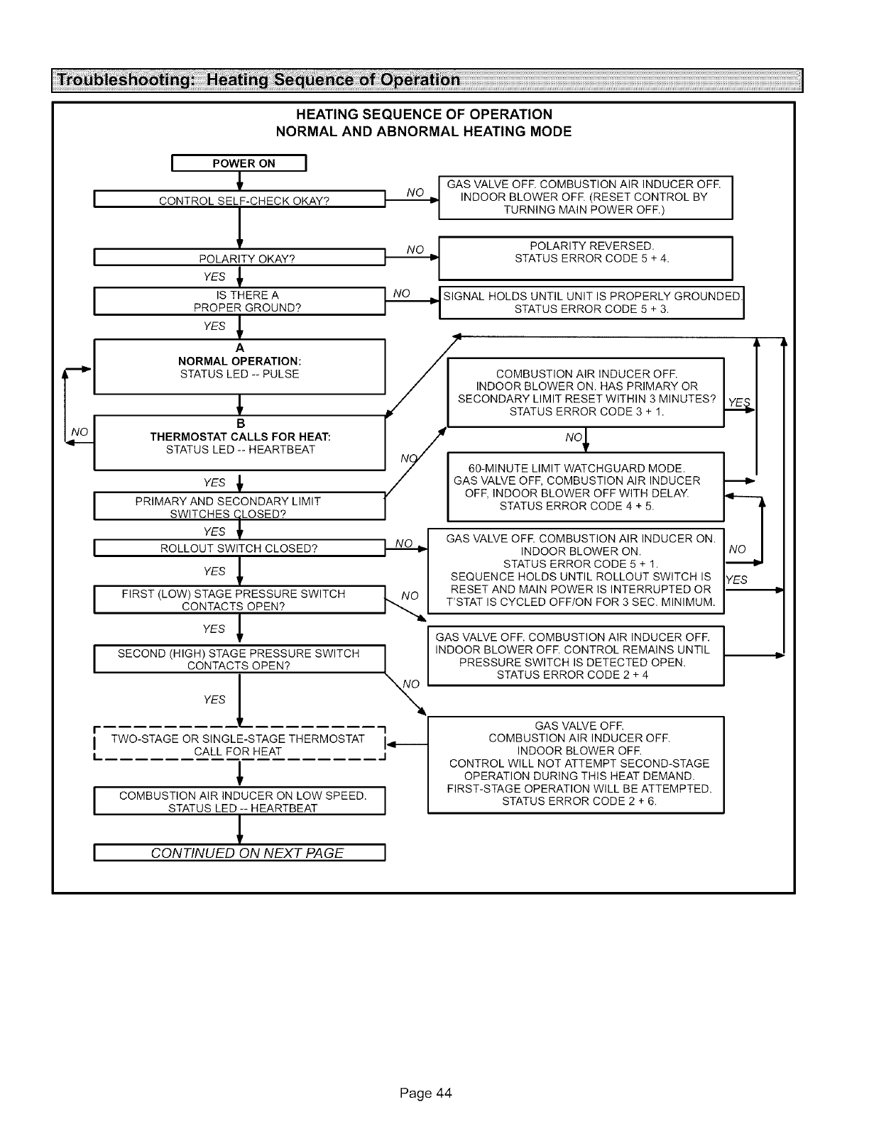
I
I
I
I
I
HEATING SEQUENCE OF OPERATION
NORMAL AND ABNORMAL HEATING MODE
I POWER ON I
CONTROL SELF-CHECK OKAY?
1
POLARITY OKAY?
YES
IS THERE A
PROPER GROUND?
YES _
I._ POLARITY REVERSED,
STATUS ERROR CODE 5 + 4,
.__.1 SIGNAL HOLDS UNTIL UNIT IS PROPERLY GROUNDED.
STATUS ERROR CODE 5 + 3.
A
NORMAL OPERATION:
STATUS LED -- PULSE
,1
B
GAS VALVE OFF. COMBUSTION AIR INDUCER OFF.
INDOOR BLOWER OFF. (RESET CONTROL BY
TURNING MAIN POWER OFF.)
COMBUSTION AIR INDUCER OFF.
INDOOR BLOWER ON. HAS PRIMARY OR
THERMOSTAT CALLS FOR HEAT:
STATUS LED -- HEARTBEAT
YES
PRIMARY AND SECONDARY LIMIT
SWITCHESyEs_LOSED?
ROLLOUT SWITCH CLOSED?
YES _
FIRST (LOW) STAGE PRESSURE SWITCH [.NO
CONTACTS OPEN?
YES _
I SECOND (HIGH)coNTACTSYESSTAGE_ PRESSUREOPEN? SWITCH I_
r I
I TWO-STAGE OR SINGLE-STAGE THERMOSTAT i._..._
LCALL FOR HEAT 1
STATUS LED -- HEARTBEAT
ICONTINUED ON NEXT PAGE I
60-MINUTE LIMIT WATCHGUARD MODE.
GAS VALVE OFF, COMBUSTION AIR INDUCER
OFF, INDOOR BLOWER OFF WITH DELAY.
STATUS ERROR CODE 4 + 5.
/
SECONDARY LIMIT RESET WITHIN 3 MINUTES? I y_:.q
STATUS ERROR CODE 3 + 1.
GAS VALVE OFR COMBUSTION AIR INDUCER ON.
INDOOR BLOWER ON.
STATUS ERROR CODE 5 + 1.
SEQUENCE HOLDS UNTIL ROLLOUT SWITCH IS
RESET AND MAIN POWER IS INTERRUPTED OR
T'STAT IS CYCLED OFF/ON FOR 3 SEC. MINIMUM,
GAS VALVE OFF. COMBUSTION AIR INDUCER OFR
INDOOR BLOWER OFR CONTROL REMAINS UNTIL
PRESSURE SWITCH IS DETECTED OPEN.
STATUS ERROR CODE 2 + 4
GAS VALVE OFR
COMBUSTION AIR INDUCER OFF.
INDOOR BLOWER OFR
CONTROL WILL NOT ATTEMPT SECOND-STAGE
OPERATION DURING THIS HEAT DEMAND.
FIRST-STAGE OPERATION WILL BE ATTEMPTED.
STATUS ERROR CODE 2 + 6.
YES
Page 44
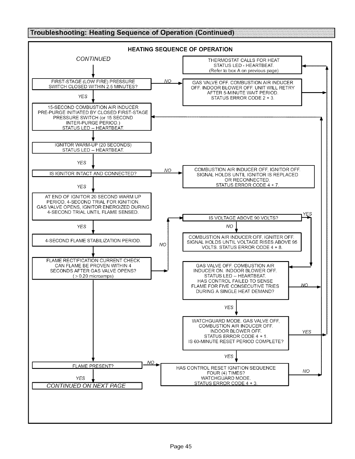
CONTINUED
HEATING SEQUENCE OF OPERATION
NO
NO
I FIRST-STAGE(LOWF,RE)PRESSUREISWITCH CLOSED WITHIN 2.5 MINUTES?
YES _
15-SECOND COMBUSTION AIR INDUCER I
m
PRE-PURGE INITIATED BY CLOSED FIRST-STAGE i
PRESSURE SWITCH (or 15 SECOND
INTER-PURGE PERIOD.)
STATUS LED -- HEARTBEAT.
[ IGNITORWARM-UPI_0SECONDStJSTATUS LED -- HEARTBEAT.
YES _
Iis IGNITOR INTACT AND CONNECTED? i
YES
I AT END OF IGNITOR 20 SECOND WARM UP I
I
PERIOD, 4-SECOND TRIAL FOR IGNITION. I
GAS VALVE OPENS, IGNITOR ENERGIZED DURING
4-SECOND TR AL UNT L FLAME SENSED,
YES
I 4-SECOND FLAME STABILIZATION PERIOD. I NO
I FLAME RECTIFICATION CURRENT CHECK
CAN FLAME BE PROVEN WITHIN 4
SECONDS AFTER GAS VALVE OPENS?
( > 0.20 microamps)
FLAMEyESPRESENT?_ IN--_-_°
CONTINUED ON NEXT PAGE J
I
[
---4
THERMOSTAT CALLS FOR HEAT
STATUS LED - HEARTBEAT.
(Refer to box A on previous page)
GAS VALVE OFR COMBUSTION AIR INDUCER
OFF. INDOOR BLOWER OFF. UNIT WILL RETRY
AFTER 5-MINUTE WAIT PERIOD,
STATUS ERROR CODE 2 + 3.
COMBUSTION AIR INDUCER OFF, IGNITOR OFF.
SIGNAL HOLDS UNTIL IGNITOR IS REPLACED
OR RECONNECTED,
STATUS ERROR CODE 4 + 7.
IS VOLTAGE ABOVE 90 VOLTS?
.o_
COMBUSTION AIR INDUCER OFF, IGNITER OFF.
SIGNAL HOLDS UNTIL VOLTAGE RISES ABOVE 95
VOLTS, STATUS ERROR CODE 4 + 8.
GAS VALVE OFF. COMBUSTION AIR Lt _r
INDUCER ON. INDOOR BLOWER OFF. I
STATUS LED -- HEARTBEAT.
HAS CONTROL FAILED TO SENSE
FLAME FOR FIVE CONSECUTIVE TRIES NO
DURING A SINGLE HEAT DEMAND?
YES lr
WATCHGUARD MODE. GAS VALVE OFF,
COMBUSTION AIR INDUCER OFR
INDOOR BLOWER OFF.
STATUS ERROR CODE 4 + 1.
IS 60-MINUTE RESET PERIOD COMPLETE?
YES _
HAS CONTROL RESET IGNITION SEQUENCE
FOUR (4) TIMES?
WATCHGUARD MODE,
STATUS ERROR CODE 4 + 3. I
J
I
YES
NO
Page 45
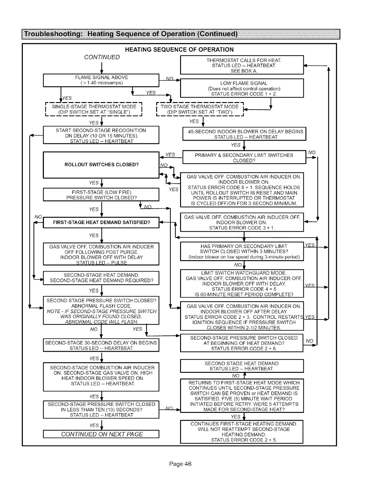
I
I
q
YES
HEATING SEQUENCE OF OPERATION
CONTINUED
FLAME SIGNAL ABOVE
(>1.40 microamps)
I SINGLE-STAGE THERMOSTAT MODE I
'L (DiP SWITCH SET AT 'SINGLE") I'
YES _
START SECOND-STAGE RECOGNITION
ON DELAY (10 OR 15 MINUTES).
STATUS LED -- HEARTBEAT
ROLLOUT SWITCHES CLOSED?
YES
I FIRST-STAGE (LOW FIRE)PRESSURE SWITCH CLOSED?
YES _l _ NO
FIRST-STAGE HEAT DEMAND SATISFIED?
YES _
GAS VALVE OFF, COMBUSTION AIR INDUCER
OFF FOLLOWING POST PURGE.
INDOOR BLOWER OFF WITH DELAY
STATUS LED -- PULSE
SECOND-STAGE 30-SECOND DELAY ON BEGINSJ
STATUS LED -- HEARTBEAT.
YES _
SECOND-STAGE COMBUSTION AIR INDUCER
ON. SECOND-STAGE GAS VALVE ON. HIGH
HEAT INDOOR BLOWER SPEED ON.
STATUS LED -- HEARTBEAT.
q SECOND-STAGE HEAT DEMAND.
SECOND-STAGE HEAT DEMAND REQUIRED?
YES _
t SECOND STAGE PRESSURE SWITCH CLOSED?
ABNORMAL FLASH CODE.
NOTE -IF SECOND-STAGE PRESSURE SWITCH
WAS ORIGINALLY FOUND CLOSED,
ABNORMAL CODE WILL FLASH.
NO _IYES _
YES
SECOND-STAGE PRESSURE SWITCH CLOSED
IN LESS THAN TEN (10) SECONDS?
STATUS LED -- HEARTBEAT
YES _
CONTINUED ON NEXT PAGE
THERMOSTAT CALLS FOR HEAT.
STATUS LED -- HEARTBEAT
SEE BOX A.
LOW FLAME SIGNAL
(Does not affect control operation)
STATUS ERROR CODE 1 + 2.
,I
I TWO STAGE THERMOSTAT MODE I_
I. (DIP SWITCH SET AT "TWO") j
YES _
I 45-SECOND INDOOR BLOWER ON DELAY BEGINS.
STATUS LED -- HEARTBEAT.
YES _
_, PRIMARY & SECONDARY LIMIT SWITCHES
CLOSED?
GAS VALVE OFF. COMBUSTION AIR INDUCER ON.
INDOOR BLOWER ON.
STATUS ERROR CODE 5 + 1. SEQUENCE HOLDS
UNTIL ROLLOUT SWITCH IS RESET AND MAIN
POWER IS INTERRUPTED OR THERMOSTAT
IS CYCLED OFF/ON FOR 3 SECOND MINIMUM.
k-
F
I GAS VALVE OFF, COMBUSTION AIR INDUCER OFF,
INDOOR BLOWER ON.
STATUS ERROR CODE 3 + 1.
I HAS PRIMARY OR SECONDARY LIMIT
SWITCH CLOSED WITHIN 3 MINUTES?
(Indoor blower on low speed during 3-minute period
NO1,
I LIMIT SWITCH WATCHGUARD MODE. I
GAS VALVE OFF, COMBUSTION AIR INDUCER OFF,
INDOOR BLOWER OFF WITH DELAY LY..ES_
STATUS ERROR CODE 4 + 5
IS 60-MINUTE RESET PERIOD COMPLETE? |
GAS VALVE OFF. COMBUSTION AIR INDUCER ON.
INDOOR BLOWER OFF AFTER DELAY.
STATUS ERROR CODE 2 + 3. CONTROL RESTARTS
IGNITION SEQUENCE IF PRESSURE SWITCH
CLOSES WITHIN 2-1/2 MINUTES.
SECOND-STAGE PRESSURE SWITCH CLOSED
AT BEGINNING OF HEAT DEMAND?
STATUS ERROR CODE 2 + 6.
YES
._.o
ISECOND STAGE HEAT DEMAND
STATUS LED -- HEARTBEAT.
No f
RETURNS TO FIRST-STAGE HEAT MODE WHICH
CONTINUES UNTIL SECOND-STAGE PRESSURE
SWITCH CAN BE PROVEN or HEAT DEMAND IS
SATISFIED. FIVE (5) MINUTE WAIT PERIOD
INITIATED BEFORE RETRY. WERE 5 ATTEMPTS
MADE FOR SECOND-STAGE HEAT?
YES _
CONTINUES FIRST-STAGE HEATING DEMAND.
WILL NOT REATTEMPT SECOND-STAGE
HEATING DEMAND,
STATUS ERROR CODE 2 + 5.
I
l
Page 46
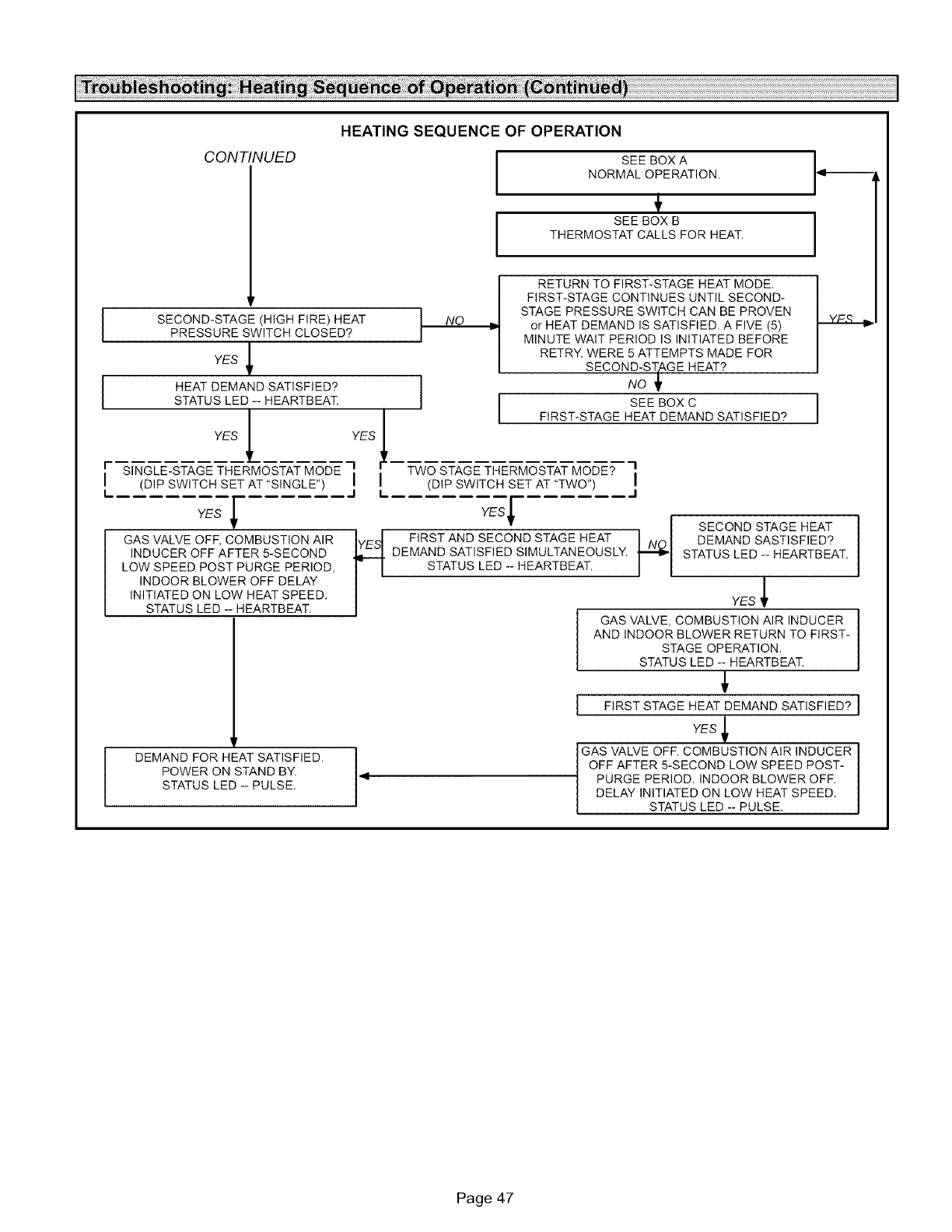
CONTINUED
HEATING SEQUENCE OF OPERATION
SEE BOX A
NORMAL OPERATION.
SEE BOX B
THERMOSTAT CALLS FOR HEAT.
I SECOND-STAGE (HIGH FIRE) HEAT
PRESSURE SWITCH CLOSED?
YES _
I HEAT DEMAND SATISFIED?
STATUS LED -- HEARTBEAT.
YES YES 1
[ SINGLE-STAGE THERMOSTAT MODE 1 I '
(DiP SWITCH SET AT "SINGLE") I I
I
L 1 I.
YES I
GAS VALVE OFF, COMBUSTION AIR
INDUCER OFF AFTER 5-SECOND
LOW SPEED POST PURGE PERIOD,
INDOOR BLOWER OFF DELAY
INITIATED ON LOW HEAT SPEED,
STATUS LED - HEARTBEAT.
DEMAND FOR HEAT SATISFIED.
POWER ON STAND BY.
STATUS LED -- PULSE.
I
I
NO
I
RETURN TO FIRST-STAGE HEAT MODE.
FIRST-STAGE CONTINUES UNTIL SECOND-
STAGE PRESSURE SWITCH CAN BE PROVEN
or HEAT DEMAND IS SATISFIED. A FIVE (5)
MINUTE WAIT PERIOD IS INITIATED BEFORE
RETRY. WERE 5 ATTEMPTS MADE FOR
SECOND-STaGE HEAT?
NO ,_
SEE BOX C
FIRST-STAGE HEAT DEMAND SATISFIED? I
TWO STAGE THERMOSTAT MODE? 3,
(DIP SWITCH SET AT "TWO") I
J
YES'f
._ SECOND STAGE HEAT
FIRST AND SECOND STAGE HEAT DEMAND SASTISFIED?
DEMAND SATISFIED SIMULTANEOUSLY. STATUS LED -- HEARTBEAT.
STATUS LED -- HEARTBEAT.
YES _
I GAS VALVE, COMBUSTION AIR INDUCER
AND INDOOR BLOWER RETURN TO FIRST-
STAGE OPERATION.
STATUS LED -- HEARTBEAT.
I FIRST STAGE HEAT DEMAND SATISFIED? I
YES
4 GAS VALVE OFF. COMBUSTION AIR INDUCER
OFF AFTER 5-SECOND LOW SPEED POST-
PURGE PERIOD. INDOOR BLOWER OFF.
DELAY INITIATED ON LOW HEAT SPEED,
STATUS LED -- PULSE,
Page 47
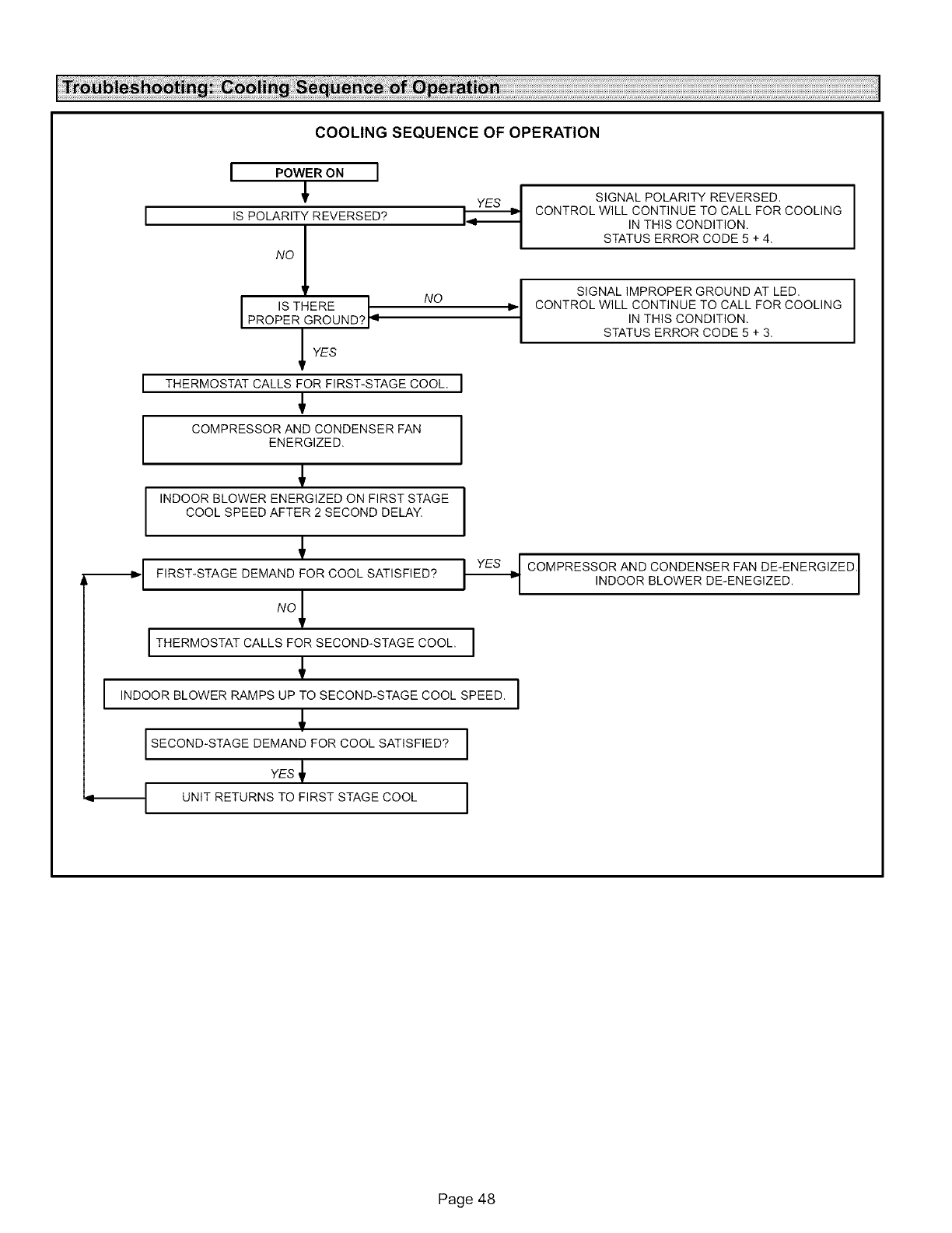
COOLINGSEQUENCEOF OPERATION
I
I
I POWER ON I
4,
IS POLARITY REVERSED?
I IS THERE NO
PROPER GROUND? 9
_YES
THERMOSTAT CALLS FOR FIRST-STAGE COOL. I
4,
COMPRESSOR AND CONDENSER FAN
ENERGIZED.
4,
INDOOR BLOWER ENERGIZED ON FIRST STAGE
COOL SPEED AFTER 2 SECOND DELAY.
SIGNAL POLARITY REVERSED.
CONTROL WILL CONTINUE TO CALL FOR COOLING
IN THIS CONDITION,
STATUS ERROR CODE 5 + 4.
SIGNAL IMPROPER GROUND AT LED.
CONTROL WILL CONTINUE TO CALL FOR COOLING
IN THIS CONDITION,
STATUS ERROR CODE 5 + 3.
4,
_1 FIRST-STAGE DEMAND FOR COOL SATISFIED?
I THERMOSTAT CALLS FOR SECOND-STAGE COOL,
4,
I ,NDOORBLOWERRAMPSUPTOSECOND-STAGECOOLSPEEDI
4,
ISECOND-STAGEDEMANDFORCOOLSAT'SF'ED?I
YES 4, I
I_ COMPRESSOR AND CONDENSER FAN DE-ENERGIZED.
NDOOR BLOWER DE-ENEG ZED.
I
Page 48
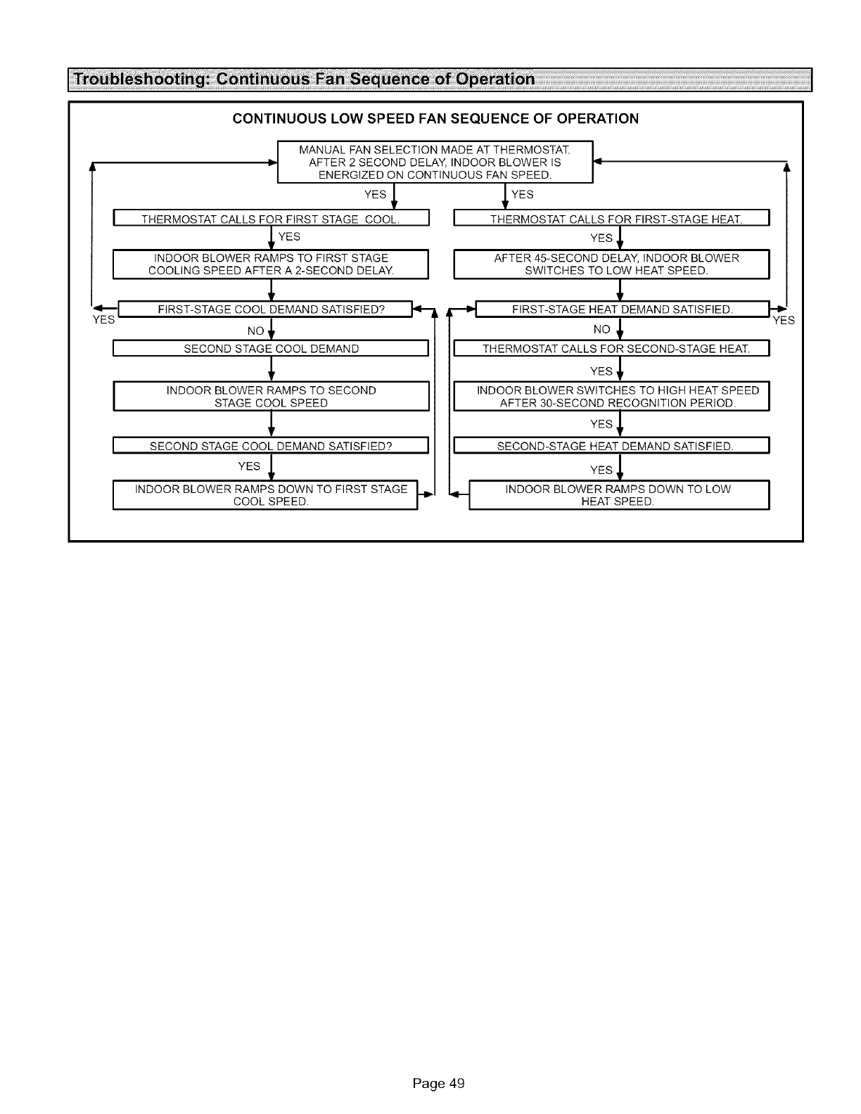
CONTINUOUSLOW SPEED FAN SEQUENCE OF OPERATION
I=
YES
I THERMOSTAT CALLS FOR FIRST STAGE COOL.
YES
I INDOOR BLOWER RAMPS TO FIRST STAGE
COOLING SPEED AFTER A 2-SECOND DELAY,
FIRST-STAGE COOL DEMAND SATISFIED?
NO_
I SECONDSTAGECOOLDEMAND I
I INDOOR BLOWER RAMPS TO SECOND
STAGE COOL SPEED
I SECONDSTAGECOOLDEMANDSAT,SFIED?I
YES
I INDOOR BLOWER RAMPS DOWN TO FIRST STAGECOOL SPEED. p
MANUAL FAN SELECTION MADE AT THERMOSTAT
AFTER 2 SECOND DELAY, INDOOR BLOWER IS
ENERGIZED ON CONTINUOUS FAN SPEED.
I I
II
I
I
I
q
ii
YES
THERMOSTAT CALLS FOR FIRST-STAGE HEAT. I
YES
AFTER 45-SECOND DELAY, INDOOR BLOWER I
SWITCHES TO LOW HEAT SPEED,
FIRST-STAGE HEAT DEMAND SATISFIED. _YI
NO
THERMOSTAT CALLS FOR SECOND-STAGE HEAT. I
YES
INDOOR BLOWER SWITCHES TO HIGH HEAT SPEED I
AFTER 30-SECOND RECOGNITION PERIOD.
YES
SECOND-STAGE HEAT DEMAND SATISFIED. I
YES
INDOOR BLOWERHEATRAMPSsPEED.DOWNTO LOW I
Page 49
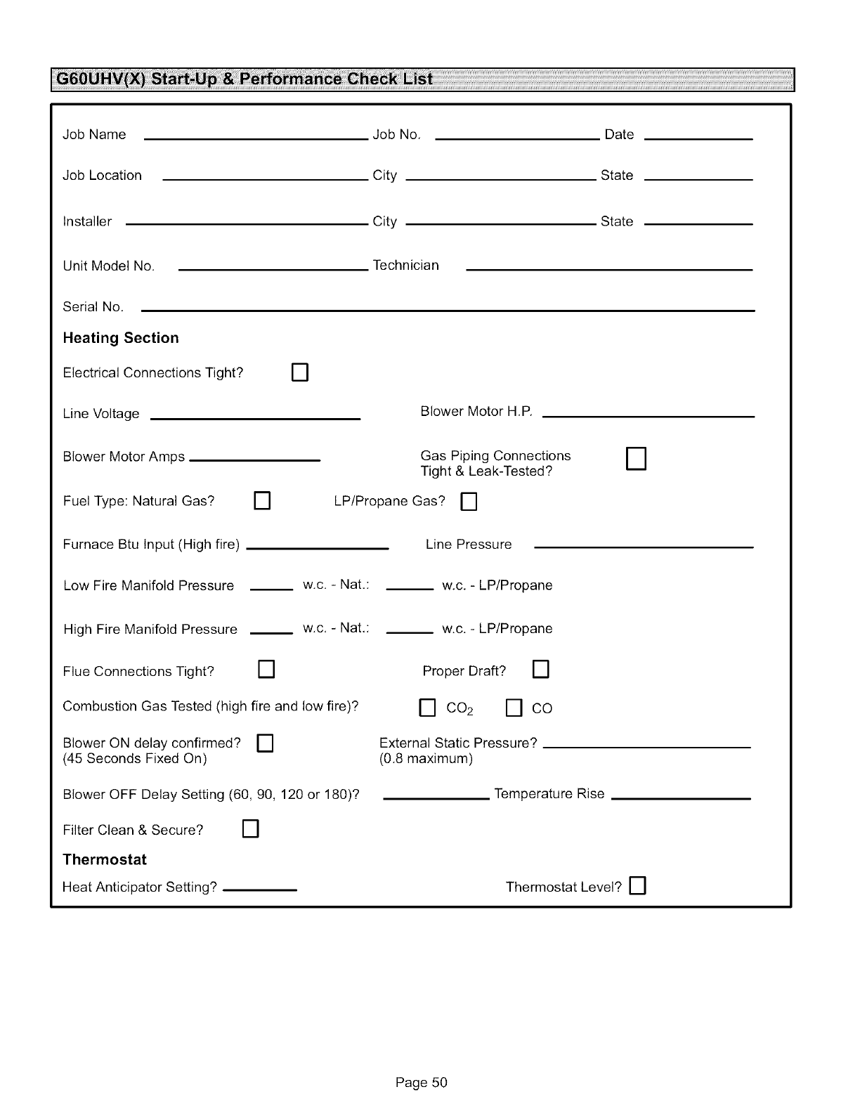
JobName
JobLocation
Installer
UnitModelNo.
SerialNo.
Heating Section
Electrical Connections Tight?
Line Voltage
Blower Motor Amps
Fuel Type: Natural Gas? []
[]
Job No.
City
City
Technician
Blower Motor H.P.
Gas Piping Connections
Tight & Leak-Tested?
LP/Propane Gas? []
Date
State
State
D
Furnace Btu Input (High fire)
Low Fire Manifold Pressure
High Fire Manifold Pressure
Flue Connections Tight? []
w.c.- Nat,:
w.c.- Nat,:
Line Pressure
__ w.c. - LP/Propane
w.c. - LP/Propane
Proper Draft? []
Combustion Gas Tested (high fire and low fire)?
Blower ON delay confirmed? []
(45 Seconds Fixed On)
Blower OFF Delay Setting (60, 90, 120 or 180)?
Filter Clean & Secure? []
Thermostat
Heat Anticipator Setting?
[] 002 [] CO
External Static Pressure?
(0.8 maximum)
Temperature Rise
Thermostat Level? []
Page 50
