LENNOX Evaporator Coils Manual L0806276
User Manual: LENNOX LENNOX Evaporator Coils Manual LENNOX Evaporator Coils Owner's Manual, LENNOX Evaporator Coils installation guides
Open the PDF directly: View PDF ![]() .
.
Page Count: 8
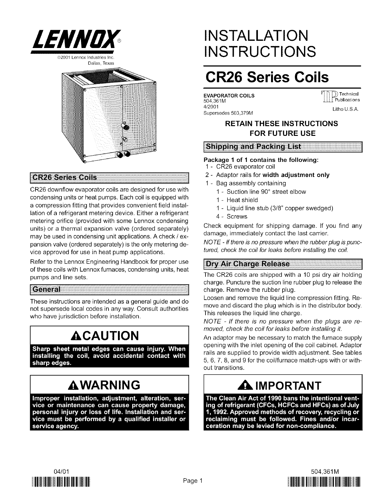
LENNOX
(c)2001 Lennox Industries Inc.
Dallas, Texas
INSTALLATION
INSTRUCTIONS
CR26 Series Coils
EVAPORATOR COILS
504,361M
4/2001
Supersedes 503,379M
F]_puTeCh nical
blications
Lithe U.S.A.
RETAIN THESE INSTRUCTIONS
FOR FUTURE USE
CR26 downflow evaporator coils are designed for use with
condensing units or heat pumps. Each coil is equipped with
a compression fitting that provides convenient field instal-
lation of a refrigerant metering device. Either a refrigerant
metering orifice (provided with some Lennox condensing
units) or a thermal expansion valve (ordered separately)
may be used in condensing unit applications. A check /ex-
pansion valve (ordered separately) is the only metering de-
vice approved for use in heat pump applications.
Refer to the Lennox Engineering Handbook for proper use
of these coils with Lennox furnaces, condensing units, heat
pumps and line sets.
These instructions are intended as a general guide and do
not supersede local codes in any way. Consult authorities
who have jurisdiction before installation.
ACAUTION
AWARNING
Package 1 of 1 contains the following:
1-CR26 evaporator coil
2-Adaptor rails for width adjustment only
1-Bag assembly containing
1 - Suction line 90° street elbow
1 - Heat shield
1 - Liquid line stub (3/8" copper swedged)
4- Screws
Check equipment for shipping damage. If you find any
damage, immediately contact the last carrier.
NOTE -If there is no pressure when the rubber plug is punc-
tured, check the coil for leaks before installing the coil.
The CR26 coils are shipped with a 10 psi dry air holding
charge. Puncture the suction line rubber plug to release the
charge. Remove the rubber plug.
Loosen and remove the liquid line compression fitting. Re-
move and discard the plug which is in the distributor body.
This releases the liquid line charge.
NOTE -If there is no pressure when the plugs are re-
moved, check the coil for leaks before installing it.
An adaptor may be necessary to match the furnace supply
opening with the inlet opening of the coil cabinet. Adaptor
rails are supplied to provide width adjustment. See tables
5, 6, 7, 8, and 9 for the coil/furnace match-ups with or with-
out transitions.
IMPORTANT
04/01
IIIHIIIIIIIIIIIIIIIIIIIIIIIIIIIIIIIII Page 1
504,361M
IIIlllIIIIIIIIIIIIIIIIIIIIIIIIIIIWIIIIII
1- See table 1 for the dimensions of the floor opening re-
quired to accommodate the supply air opening and the
plenum. If the unit is installed against a wall, the rear
edge of the opening must be at least 1" (25 mm) from
the wall. Cut an appropriately sized opening,
Table 1
Floor Opening
Unit
CR26-18N, -30N, -36N
CR26-36W, -48N, -60N
CR26-48W
CR26-60W
Side to Side
14-1/4" (3.6 m)
19-1/4" (4.9 m)
24-1/4" (6.2 m)
24-1/4" (6.2 m)
Front to Rear
22-1/8" (5.6 m)
22-1/8" (5.6 m)
22-1/8" (5.6 m)
22-1/8" (5.6 m)
2- Lower the plenum through the floor opening. Align the
flanges on the base of the unit with the matching
flanges on the plenum, then lower the unit over the ple-
num. The coil cabinet must be level or sloped slightly
toward the drain outlet and secured and sealed to the
plenum, If the furnace and coil cabinet are the same
size, skip to step four.
Adjusting the Coil Cabinet Width
3- Install the provided adaptor rails or filler pieces on the
coil if necessary. Align the adaptor rails with the rear
of the coil cabinet. Figure 2 illustrates how the furnace,
coil, and adapter rails fit together,
G40/50 Furnace Applications -
Use the provided rails to match the coil to the furnace.
Refer to tables 5 through 9 for correct rail widths,
Place the adaptor rail flat on the top of the coil cabinet.
See figure 1, Bend the short flange up 90° at the perfo-
ration. Use the four provided screws to secure the rails
to the coil cabinet,
Adaptor Short
Adaptor Rail Rails Flange
Installation bend)
Align the adaptor
rail with the rear of
the coil cabinet.
Secure With
Two Screws
On Each Side
Figure 1
Gas Furnace with
Adaptor Rails and Coil
gas
furnace
Seal
between
adaptor
and furnace.
adaptor
rails
short flange the
(90° angle) rail
the rear
of the coil
CR26 cabinet.
coil
J
FILLER PIECES
Figure 2
Applications other than the G40/G50 -
If you use the CR26 coil with furnaces other than the
G40/G50, and the furnace's width is smaller than the
coil inlet opening, install filler pieces (field-provided).
See figure 3,
If the supply opening on the furnace is larger than the
evaporator cabinet inlet opening, use an adaptor and
furnace support (field-provided). See figure 4.
FURNACE I
FILLER PIECES
AIR FLOW
CR26
PLENUM
Figure 3
Seal between
filler pieces
and furnace.
Page 2
FURNACE
SUPPORT
FURNACE
,_ADAPTOR!
AIR FLOW
0
CR26
PLENUM
Seal between
furnace supports
Jand furnace.
Figure 4
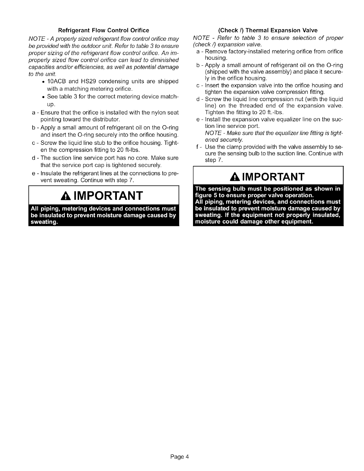
ACAUTION
4- Seal between the furnace cabinet and the coil cabinet
to prevent air leaks.
5- As you lower the furnace onto the coil, align the flanges
of the furnace and the the coil cabinet,
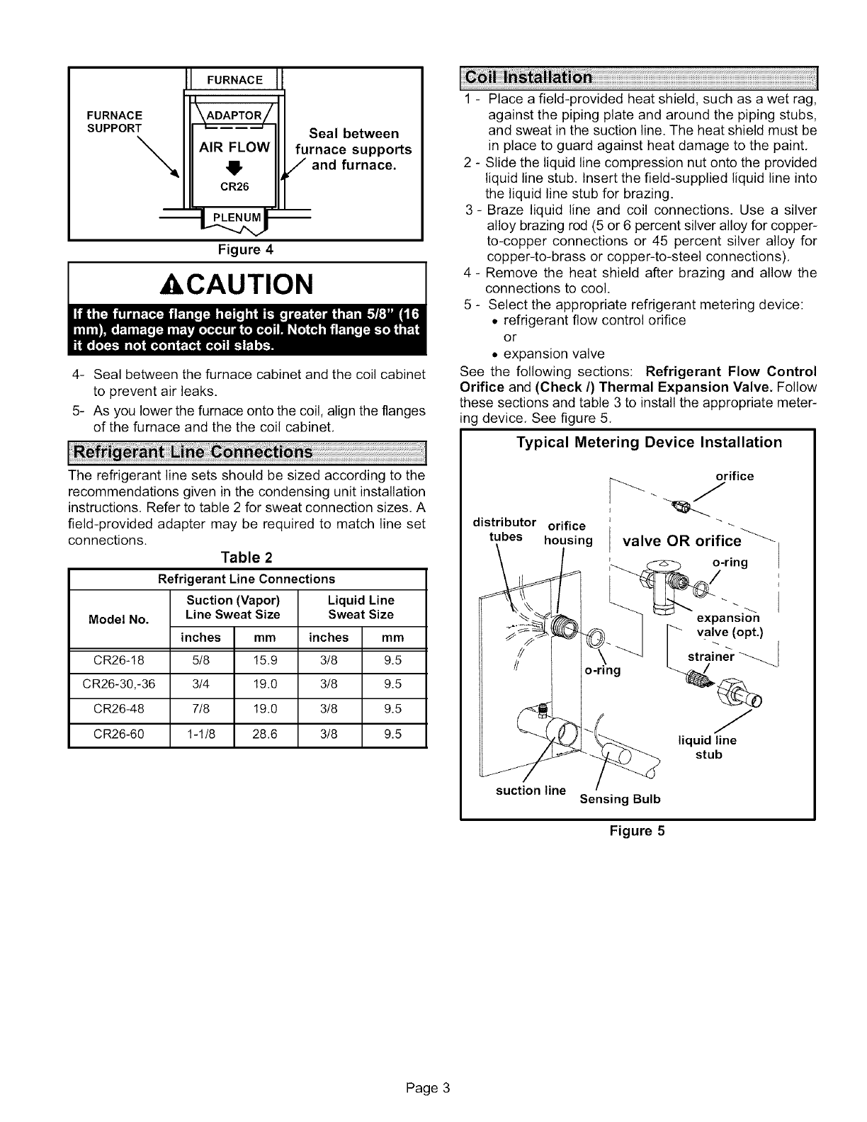
The refrigerant line sets should be sized according to the
recommendations given in the condensing unit installation
instructions, Refer to table 2 for sweat connection sizes, A
field-provided adapter may be required to match line set
connections.
Table 2
Refrigerant Line Connections
Model No.
mm
CR26-18 9.5
CR26-30,-36 9.5
CR26-48 9.5
CR26-60 9.5
Suction (Vapor)
Line Sweat Size
inches mm
5/8 15.9
3/4 19.0
7/8 19.0
1-1/8 28.6
Liquid Line
Sweat Size
inches
3/8
3/8
3/8
3/8
1 - Place a field-provided heat shield, such as a wet rag,
against the piping plate and around the piping stubs,
and sweat in the suction line. The heat shield must be
in place to guard against heat damage to the paint,
2 - Slide the liquid line compression nut onto the provided
liquid line stub. Insert the field-supplied liquid line into
the liquid line stub for brazing.
3- Braze liquid line and coil connections. Use a silver
alloy brazing rod (5 or 6 percent silver alloy for copper-
to-copper connections or 45 percent silver alloy for
copper-to-brass or copper-to-steel connections),
4- Remove the heat shield after brazing and allow the
connections to cool.
5 - Select the appropriate refrigerant metering device:
• refrigerant flow control orifice
or
• expansion valve
See the following sections: Refrigerant Flow Control
Orifice and (Check/) Thermal Expansion Valve. Follow
these sections and table 3 to install the appropriate meter-
ing device, See figure 5,
Typical Metering Device Installation
distributor orifice
tubes housing
orifice
valve OR orifice _
o-ring
o-ring
expansion
valve (opt.)
strainer
liquid line
stub
suction line Sensing Bulb
Figure 5
Page 3
Refrigerant Flow Control Orifice
NOTE -A properly sized refrigerant flow control orifice may
be provided with the outdoor unit. Refer to table 3 to ensure
proper sizing of the refrigerant flow control orifice. An im-
properly sized flow control orifice can lead to diminished
capacities and/or efficiencies, as well as potential damage
to the unit.
• 10ACB and HS29 condensing units are shipped
with a matching metering orifice,
• See table 3 for the correct metering device match-
up.
a - Ensure that the orifice is installed with the nylon seat
pointing toward the distributor.
b - Apply a small amount of refrigerant oil on the O-ring
and insert the O-ring securely into the orifice housing,
c - Screw the liquid line stub to the orifice housing, Tight-
en the compression fitting to 20 ft-lbs,
d - The suction line service port has no core, Make sure
that the service port cap is tightened securely.
e - Insulate the refrigerant lines at the connections to pre-
vent sweating, Continue with step 7.
A IMPORTANT
(Check/) Thermal Expansion Valve
NOTE -Refer to table 3 to ensure selection of proper
(check/) expansion valve.
a - Remove factory-installed metering orifice from orifice
housing,
b - Apply a small amount of refrigerant oil on the O-ring
(shipped with the valve assembly) and place it secure-
ly in the orifice housing,
c - Insert the expansion valve into the orifice housing and
tighten the expansion valve compression fitting.
d - Screw the liquid line compression nut (with the liquid
line) on the threaded end of the expansion valve,
Tighten the fitting to 20 ft.-Ibs.
e - Install the expansion valve equalizer line on the suc-
tion line service port.
NOTE -Make sure that the equalizer line fitting is tight-
ened securely.
f - Use the clamp provided with the valve assembly to se-
cure the sensing bulb to the suction line. Continue with
step 7.
,& IMPORTANT
Page 4
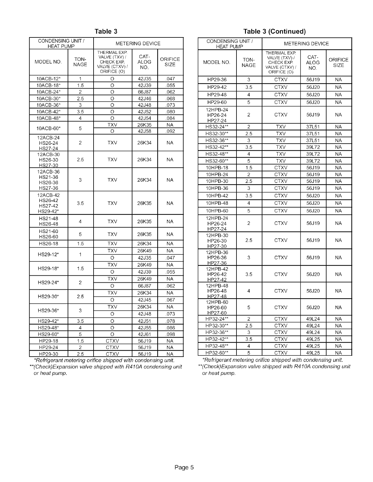
Table 3 Table 3 (Continued)
CONDENSING UNIT /
HEAT PUMP
MODEL NO. TON-
NAGE
10ACB-12* 1
10ACB-18* 1.5
10ACB-24* 2
10ACB-30* 2.5
10ACB-36* 3
10ACB-42* 3.5
10ACB-48* 4
10ACB-60* 5
12ACB-24
HS26-24 2
HS27-24
12ACB-30
HS26-30 2.5
HS27-30
12ACB-36
HS21-36 3
HS26-36
HS27-36
12ACB-42
HS26-42 3.5
HS27-42
HS29-42"
HS21-48
HS26-48 4
HS21-60
HS26-60 5
HS26-18 1.5
HS29-12* 1
HS29-18* 1.5
HS29-24" 2
HS29-30" 2.5
HS29-36" 3
HS29-42" 3.5
HS29-48" 4
HS29-60" 5
HP29-18 1.5
HP29-24 2
HP29-30 2.5
METERING DEVICE
THERMALEXR
VALVE(TXV)/ CAT- ORIFICE
CHECKEXR ALOG SIZE
VALVE(CTXV) /NO.
ORIFICE (O)
O 42J35 .047
O 42J39 .055
O 66J87 .062
O 42J46 .068
O 42J48 .073
O 42J52 .080
O 42J54 .084
TXV 26K35 NA
O 42J58 .092
TXV 26K34 NA
TXV 26K34 NA
TXV 26K34 NA
TXV 26K35 NA
TXV 26K35 NA
TXV 26K35 NA
TXV 26K34 NA
TXV 26K49 NA
O 42J35 .047
TXV 26K49 NA
O 42J39 .055
TXV 26K49 NA
O 66J87 .062
TXV 26K34 NA
O 42J45 .067
TXV 26K34 NA
O 42J48 .073
O 42J51 .078
O 42J55 .086
O 42J61 .098
CTXV 56J19 NA
CTXV 56J19 NA
CTXV 56J19 NA
*Refrigerant metering orifice shipped with condensing unit.
**(Check)Expansion valve shipped with R410A condensing unit
or heat pump.
CONDENSING UNIT/ METERING DEVICE
HEAT PUMP
THERMAL EXR
MODEL NO. TON- VALVE(TXV)/CAT- ORIFICE
CHECK EXR ALOG
NAGE VALVE(CTXV) /NO. SIZE
ORIFICE (O)
HP29-36 3 CTXV 56J 19 NA
HP29-42 3.5 CTXV 56J20 NA
HP29-48 4 CTXV 56J20 NA
HP29-60 5 CTXV 56J20 NA
12HPB-24
HP26-24 2 CTXV 56J 19 NA
HP27-24
HS32-24"* 2 TXV 37L51 NA
HS32-30"* 2.5 TXV 37L51 NA
HS32-36"* 3 TXV 37L51 NA
HS32-42"* 3.5 TXV 39L72 NA
HS32-48"* 4 TXV 39L72 NA
HS32-60"* 5 TXV 39L72 NA
10HPB-18 1.5 CTXV 56J19 NA
10H PB-24 2 CTXV 56J 19 NA
10H PB-30 2.5 CTXV 56J 19 NA
10H PB-36 3 CTXV 56J 19 NA
10H PB-42 3.5 CTXV 56J20 NA
10HPB-48 4 CTXV 56J20 NA
10H PB-60 5 CTXV 56J20 NA
12HPB-24
HP26-24 2 CTXV 56J 19 NA
HP27-24
12HPB-30
HP26-30 2.5 CTXV 56J19 NA
HP27-30
12HPB-36
HP26-36 3 CTXV 56J 19 NA
HP27-36
12HPB-42
HP26-42 3.5 CTXV 56J20 NA
HP27-42
12HPB-48
HP26-48 4 CTXV 56J20 NA
HP27-48
12HPB-60
HP26-60 5 CTXV 56J20 NA
HP27-60
HP32-24"* 2 CTXV 49L24 NA
HP32-30"* 2.5 CTXV 49L24 NA
HP32-36"* 3 CTXV 49L24 NA
HP32-42"* 3.5 CTXV 49L25 NA
HP32-48"* 4 CTXV 49L25 NA
HP32-60"* 5 CTXV 49L25 NA
*Refrigerant metering orifice shipped with condensing unit.
**(Check)Expansion valve shipped with R4 IOA condensing unit
or heat pump.
Page 5
Makedrainconnectionsfromthe3/4"(19mm)pipenipple
onpanwitha 3/4"(19mm)drainpipe.Routedrainpipe
downwardtoanopendrainorsump,Neverconnectdrain
toa closedsystem.
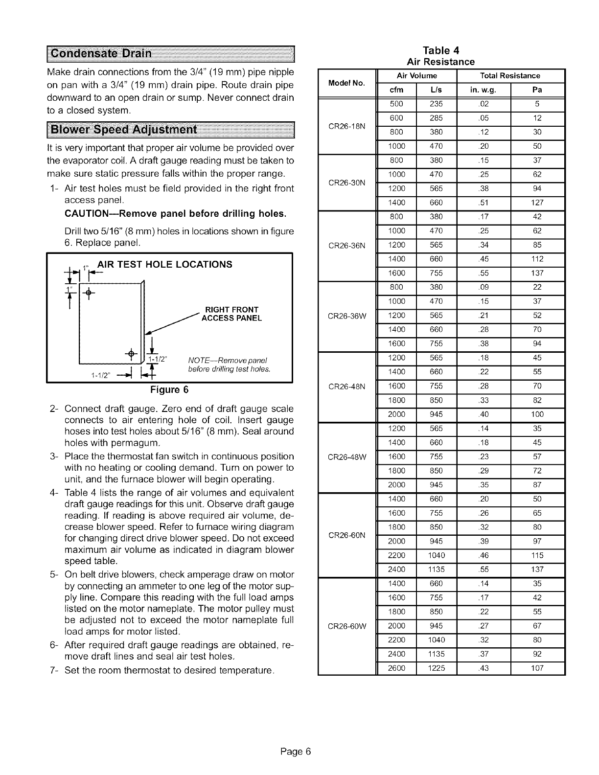
Itisveryimportantthatproperairvolumebeprovidedover
theevaporatorcoil.Adraftgaugereadingmustbetakento
makesurestaticpressurefallswithintheproperrange.
1- Airtestholesmustbefieldprovidedintherightfront
accesspanel.
CAUTION--Remove panel before drilling holes.
Drill two 5/16" (8 mm) holes in locations shown in figure
6, Replace panel.
_ t,_____IRTEST HOLE LOCATIONS
t+ RIGHT FRONT
_ACCESS PANEL
+l 1-1/2' NO TE--Remove panel
t-1/2" --_ _T- before drilling test holes.
Figure 6
2- Connect draft gauge. Zero end of draft gauge scale
connects to air entering hole of coil. Insert gauge
hoses into test holes about 5/16" (8 mm), Seal around
holes with permagum,
3- Place the thermostat fan switch in continuous position
with no heating or cooling demand. Turn on power to
unit, and the furnace blower will begin operating,
4- Table 4 lists the range of air volumes and equivalent
draft gauge readings for this unit, Observe draft gauge
reading, If reading is above required air volume, de-
crease blower speed, Refer to furnace wiring diagram
for changing direct drive blower speed, Do not exceed
maximum air volume as indicated in diagram blower
speed table,
5- On belt drive blowers, check amperage draw on motor
by connecting an ammeter to one leg of the motor sup-
ply line, Compare this reading with the full load amps
listed on the motor nameplate. The motor pulley must
be adjusted not to exceed the motor nameplate full
load amps for motor listed,
6- After required draft gauge readings are obtained, re-
move draft lines and seal air test holes,
7- Set the room thermostat to desired temperature,
Table 4
Air Resistance
Air Volume
Mode! No. cfm L/s
500 235
600 285
CR26-18N 800 380
1000 470
800 380
1000 470
CR26-30N 1200 565
1400 660
800 380
1000 470
CR26-36N 1200 565
1400 660
1600 755
800 380
1000 470
CR26-36W 1200 565
1400 660
1600 755
1200 565
1400 660
CR26-48N 1600 755
1800 850
2000 945
1200 565
1400 660
CR26-48W 1600 755
1800 850
2000 945
1400 660
1600 755
1800 850
CR26-60N 2000 945
2200 1040
2400 1135
1400 660
1600 755
1800 850
CR26-60W 2000 945
2200 1040
2400 1135
2600 1225
Total Resistance
in. w.g. Pa
.02 5
.05 12
.12 30
.20 50
15 37
25 62
38 94
51 127
17 42
25 62
34 85
45 112
55 137
09 22
15 37
21 52
28 70
38 94
18 45
22 55
,28 70
33 82
40 100
14 35
18 45
23 57
29 72
35 87
20 50
26 65
32 80
39 97
46 115
55 137
14 35
17 42
22 55
27 67
32 80
37 92
43 107
Page 6
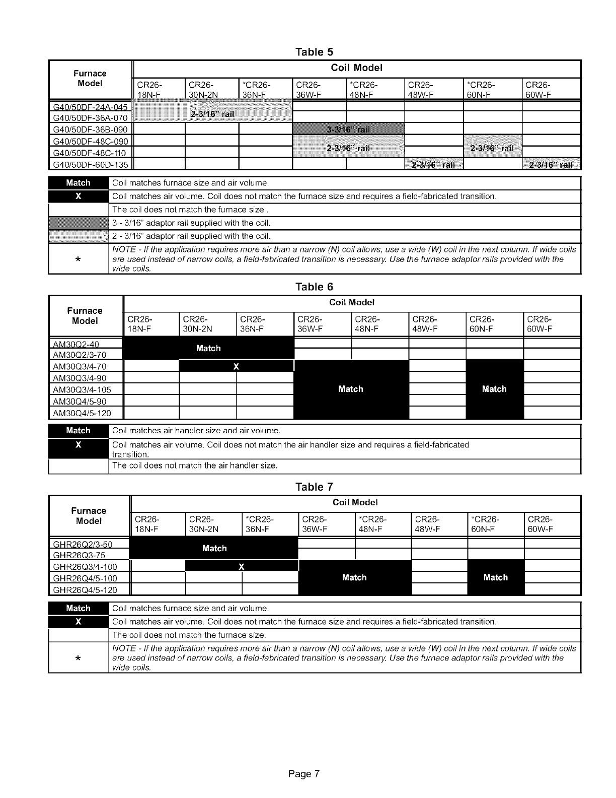
Furnace
Model
G40/50DF-24A-045
G40/50DF-36A-070
G40/50DF-36B-090
G40/50DF-48C-090
G40/50DF-48C-110
G40/50DF-60D-135
Table 5
Coil Model
CR26- CR26- *CR26- CR26- *CR26- CR26- *CR26- CR26-
18N-F 30N-2N 36N-F 36W-F 48N-F 48W-F 60N-F 60W-F
iiiiiiiiiiiiiiiiiiiiiiiiiiiiiiiiiiiiiiiiiiiiiiiiiiiiiiiiiiiiiiiili_liilllliiiiliiiillliiillli_iiliiiliiilii!!liiiilliiiiliiillilliiiii!!_iiiiiiiiiiiiiiiiiiiiiiiiiiiiiiiiiiil_!_iiiii:!il¸i¸ill¸ii!iiiiiiii!iiiiiiiiiiiiiiiiii!i!!iiiiiiiiiiiiiiiiiiiiiiiiiiiiiiiill¸i!i!iiiiiiiiiiiiill
iiiiiiiiiiiiiiiiiiiiiiiiiiiiiiiiiiiiiiiiiiiiiiiiiiiiiiiiiiiiiiiiiiiiiiiiiiiiiiiiiiiiiiiiiiiiiiiiiiiiiiiiiiiiiiiiiiiiii;iiii:
Furnace
Model
Coil matches furnace size and air volume.
Coil matches air volume. Coil does not match the furnace size and requires a field-fabricated transition.
The coil does not match the furnace size.
3 - 3/16" adaptor rail supplied with the coil.
2 - 3/16" adaptor rail supplied with the coil.
NOTE -ff the application requires more air than a narrow (N) coil allows, use a wide (W) coil in the next column, ff wide coils
are used instead of narrow coils, a field-fabricated transition is necessary. Use the furnace adaptor rails provided with the
wide coils.
AM30Q2/3-70
AM30Q3/4-70
AM30Q3/4-90
AM30Q3/4-105
AM30Q4/5-90
AM30Q4/5-120
CR26-
18N-F
CR26- CR26-
30N-2N 36N-F
Table 6
Coil Model
CR26- I CR26-
36W-F t 48N-F
CR26-
48W-F
CR26-
60N-F
CR26-
60W-F
Coil matches air handler size and air volume.
Coil matches air volume. Coil does not match the air handler size and requires a field-fabricated
transition.
I The coil does not match the air handler size.
Furnace
Model
GHR26Q3-75
GHR26Q3/4-100
GHR26Q4t5-100
GHR26Q4t5-120
CR26- CR26- *CR26-
18N-F 30N-2N 36N-F
Table 7
Coil Model
CR26- I *CR26-
36W-F t48N-F
t CR26-
48W-F
*CR26-
60N-F
CR26-
60W-F
ICoil matches furnace size and air volume.
Coil matches air volume. Coil does not match the furnace size and requires a field-fabricated transition.
The coil does not match the furnace size.
NOTE -ff the application requires more air than a narrow (N) coil allows, use a wide (W) ceil in the next column, ff wide coils
are used instead of narrow coils, a field-fabricated transition is necessary. Use the furnace adaptor rails provided with the
wide coils.
Page 7
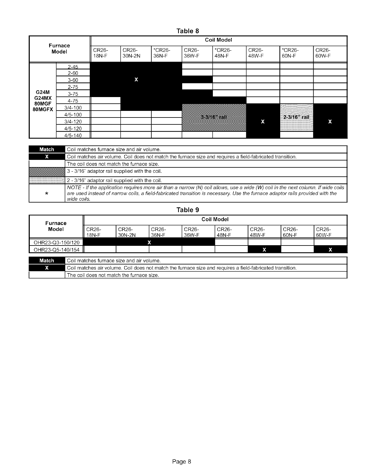
Furnace
Model CR26-
18N-F
CR26-
30N-2N
*CR26-
36N-F
Table 8
CR26-
36W-F
Coil Model
*CR26-
48N-F
CR26-
48W-F
*CR26-
60N-F
CR26-
60W-F
2-60
3-60
2-75
G24M 3-75
G24MX 4-75
80MGF
80MGFX 3/4-100
4/5-100
3/4-120
4t5-120
4t5-140
iiiiiiiiiiiiiiiiiiiiiiiiiiiiiiiiiiiiiiiiiiiiiiiiiiiiiiiiiiiiiiiiiiiiiiiiiiiiiiiiiiiiiiiiiiiiiiiiiiiiiiiiiiiiiiiiiiiiiiiil_
Coil matches furnace size and air volume.
Coil matches air volume. Coil does not match the furnace size and requires a field-fabricated transition.
The coil does not match the furnace size.
3 - 3/16" adaptor rail supplied with the coil.
2 - 3/16" adaptor rail supplied with the coil.
NOTE -ff the application requires more air than a narrow (N) coil allows, use a wide (W) coil in the next column, ff wide coils
are used instead of narrow coils, a field-fabricated transition is necessa_ Use the furnace adaptor rails provided with the
wide coils.
Furnace
Model
OHR23-Q3-150/120
OHR23-Q5-140/154
CR26- CR26-
18N-F 30N-2N
Table 9
Coil Model
CR26-
48W-F
CR26-
60N-F
CR26-
60W-F
Coil matches furnace size and air volume.
Coil matches air volume. Coil does not match the furnace size and requires a field-fabricated transition.
The coil does not match the furnace size.
Page 8
