LENNOX Controls And HVAC Accessories Manual L0806363
User Manual: LENNOX LENNOX Controls and HVAC Accessories Manual LENNOX Controls and HVAC Accessories Owner's Manual, LENNOX Controls and HVAC Accessories installation guides
Open the PDF directly: View PDF ![]() .
.
Page Count: 24
ZENNOX
t,_2004 Lennox industries Inc,
Dallas, Texas, USA
HEAT PUMP
KITS AND ACCESSORIES
_pu Technical
blications
Lithe U.S.A.
502,755M
09/2004
Supersedes 05/2003
FUELMASTER 21 ¢
CONTROL BOARD
INSTALLATION INSTRUCTIONS FOR FUELMASTER 21 ¢(FM21) CONTROL BOARD
Package 1 of 1 contains:
1 - FM21 board
1 - Mounting box with cover
1 - Bag assembly containing:
4 - #8 - 18 x 1/2" screws
The FM21 FueIMaster 21° control board is designed for
use with a conventional gas or oil furnace in combination
with a heat pump.Optional kits for service light (SLC1)
and defrost thermostat probe (DTR1) are available. An
outdoor thermostat may be used with the FM21 when
low temperature heat pump lockout is desired.
NOTE -A time delay relay (54G5701) is required when
an outdoor thermostat is used.
When the outdoor temperature is below the outdoor ther-
mostat setting, the time delay relay (DL10) will provide a
two-second delay before the compressor contactor is
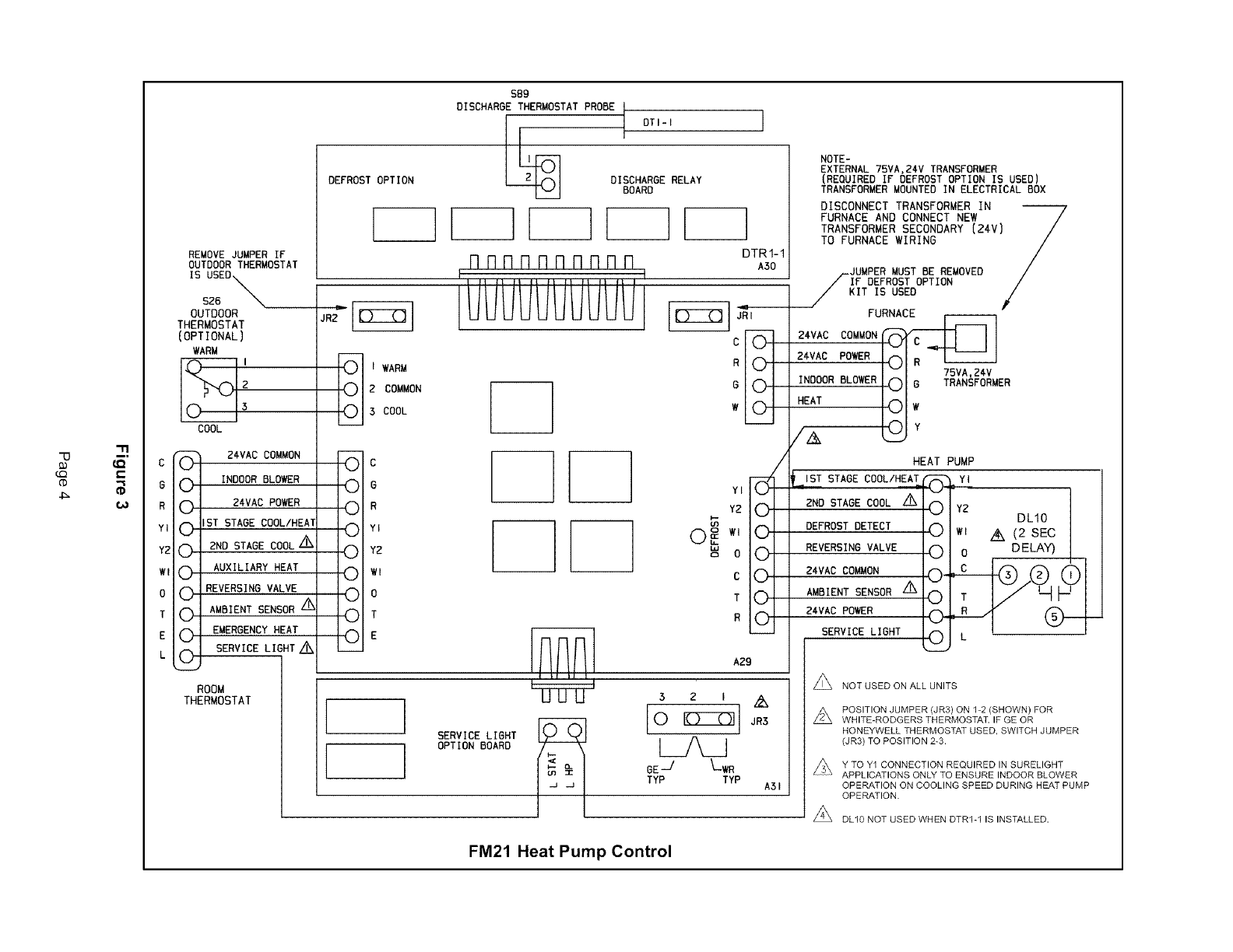
energized. Refer to figure 3 for field wiring.
During a call for heat with the FM21, the heat pump will
provide first- stage heating. However, if first-stage op-
eration does not satisfy the heating demand, second-
stage heat is provided by the furnace as the secondary
source of heat. The FM21 automatically terminates heat
pump operation and starts the furnace.
The FM21 also controls the indoor blower speed. The in-
door blower runs in high speed during first-stage heating
(provided by the heat pump). When there is a need for
second-stage heating, the FM21 stops the blower, al-
lows the furnace heat exchanger to warm up, and then
operates the indoor blower on heating speed. In situa-
tions that require the blower to run continuously, the
blower speed will change automatically from heat pump
(high speed) to furnace (heating speed).
If the optional defrost thermostat probe, DTR1, is used,
the indoor blower will run continuously on high speed
during both first-stage and second-stage heating without
interruption.
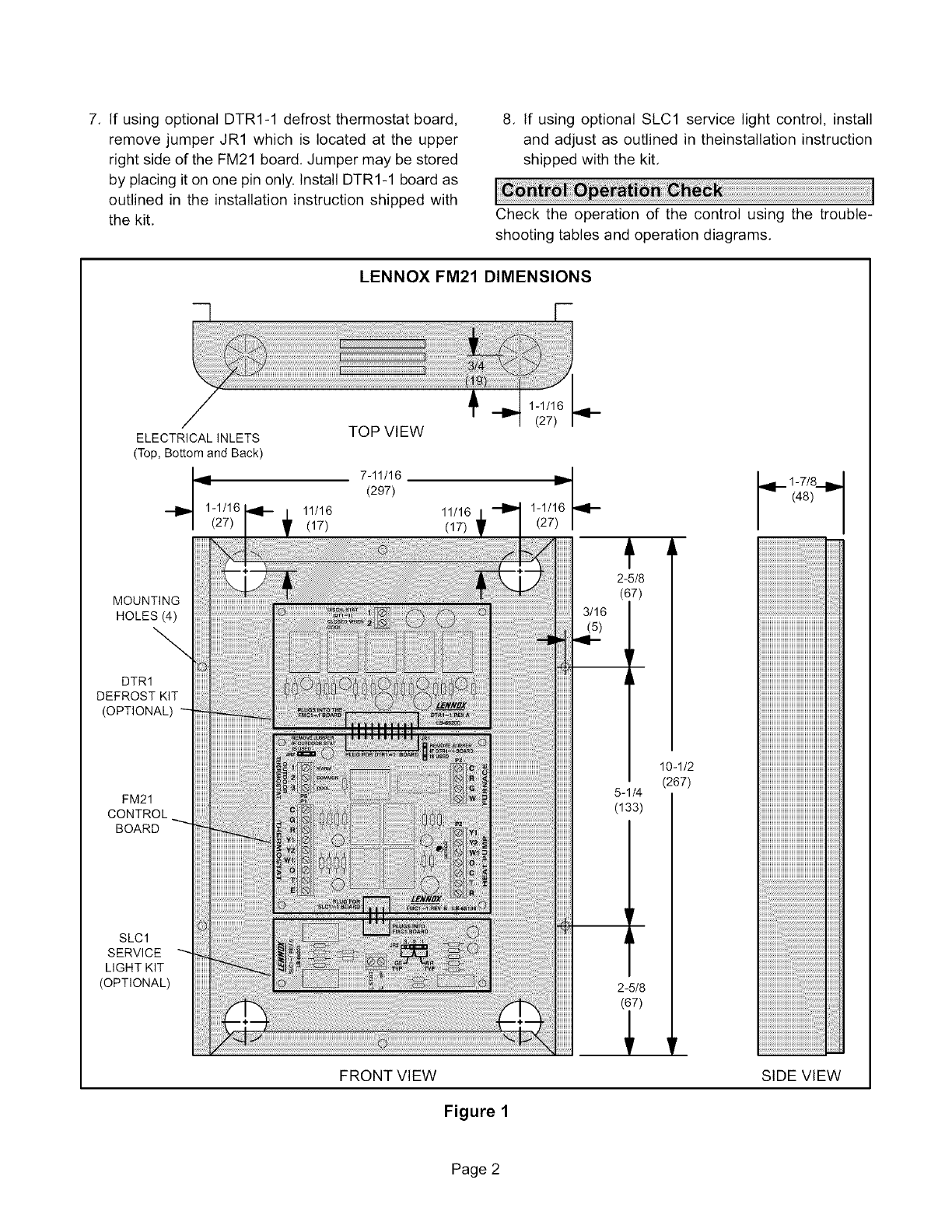
1. Determine an appropriate indoor location close to
the furnace to install the FM21 control box. The box
may be installed on the furnace to facilitate wiring.
IMPORTANT
.
.
.
5.
6.
Use the provided screws to secure the control box.
Refer to figure 1 for dimensions.
NOTE -Standard 18-gauge thermostat wire is rec-
ommended for all wiring.
Remove the FM21 control box cover and make the
thermostat connections to the FM21 board, Termi-
nals for the thermostat connections are located on
the left side of the FM21 board,
Make furnace and heat pump connections to termi-
nals on the FM21 board, These terminals are lo-
cated on the right side of the FM21 board,
NOTE -If the furnace is equipped with a SureLighltb
ignition control board, a wire must be connected
from the heat pump Y1 terminal on the FM21 board
to the Y terminal on the furnace SureLight ignition
control board. This will ensure indoor blower opera-
tion on cooling speed during heat pump operation.
Run wires through the electrical inlets as shown in
figure 2.
If outdoor thermostat (S26) is being used with FM21,
remove jumper JR2 that is located on the upper left
side of the FM21 board. The jumper may be stored
by placing it on one pin only. Wire the outdoor ther-
mostat (S26) to the outdoor thermostat terminals on
the FM21 board. See figure 3 for wiring.
Page 1
7. If usingoptionalDTRI-1defrostthermostatboard,
removejumperJR1whichis locatedat theupper
rightsideoftheFM21board.Jumpermaybestored
byplacingitononepinonly.InstallDTRI-1boardas
outlinedintheinstallationinstructionshippedwith
thekit,
8. If usingoptionalSLC1servicelightcontrol,install
andadjustasoutlinedintheinstallationinstruction
shippedwiththekit,
Checktheoperationof the controlusingthe trouble-
shootingtablesandoperationdiagrams.
LENNOX FM21 DIMENSIONS
MOUNTING
HOLES (4)
DTR1
DEFROST KIT
(OPTIONAL)
FM21
CONTROL
BOARD
SLCl
SERVICE
LIGHT KIT
(OPTIONAL)
FRONT VIEW
2-5/8
(67)
3/16
(5)
5-1/4
(133)
2-5/8
(67)
10-1/2
(267)
1-7/8
_!-- (48)_"
SIDE VIEW
Figure 1
Page 2
ToOptionalOutdoor
Thermostat(3wires)
LENNOX FM21 WIRING INLETS
To Optional DTRI-1
Probe (2 wires)
To Furnace (5 wires)
MOUNTING
HOLES (4) _
DTR1
DEFROST KIT
(OPTIONAL)
Wire used only
if furnace is
/equipped with
SureLight ignition
control board
FM21
CONTROL
BOARD
SLCl SERVICE
LIGHT KIT
(OPTIONAL)
To Room
Thermostat (10
wires maximum) FRONT VIEW
Figure 2
To Heat Pump (8
wires maximum)
Page 3
"-O
(.Q
(D
4_
"11
(_" C
(- G
CD
R
YI
Y2
WI
0
T
E
L
REMOVE JUMPER IF
OUTDOOR THERMOSTAT
IS USEO_
sz6 N
OUTDOOR
THERMOSTAT
(OPTIONAL)
WARM
COOL
" 24VAC COMMON
0INDOOR BLOWER
024VAC POWER
0 IST STAGE COOL/HEAT
(_ 2ND STAGE COOL '/_
0 AUXILIARY HEAT
0 REVERSING VALVE
0 AMBIENT SENSOR "/_
0EMERGENCY HEAT
SERVICE LIGHT ZZiX
0
ROOM
THERMOSTAT
DEFROST OPTION
SB9
DISCHARGE THERMOSTAT PROBE
OTl-i
DISCHARGE RELAY
BOARD
]
FIRRRRRRRRR
I r
LUUUUUUUUUUI
]
DTRI-I
A30
R
G
W
IWARM
2 COMMON
3 COOL
0 C
0 o
O R
0 Yi
0 YZ
0wl
0 o
0 T
OE
SERVICE LIGHT
OPTION BOARD
YI
Y2
0 _ w,
b_ o
C
T
R
A2g
5 z i A
0 _ JR5
Z_
DE -/ LWR
TYP TYP A31
FM21 Heat Pump Control
NOTE -
EXTERNAL 75VA,24V TRANSFORMER
(REQUIRED IF DEFROST OPTION IS USED)
TRANSFORMER MOUNTED IN ELECTRICAL BOX
DISCONNECT TRANSFORMER IN 7
FURNACE AND CONNECT NEW /
TRANSFORMER SECONDARY {24V) /
TO FURNACE WIRING /
/
/-.JUMPER MUST BE REMOVED /
/IF DEFROST OPTION /
/KIT IS USED /
FUR C
'VA° OI'C-&l II
Z4VACPOWER DIR I_l
BLOWER - I 75VA,24.V
INDOOR 91 G TRANSFORMER
Y2 DLIO
DEFROST DETECT @1 Z_ (2 SEC
REVERSING VALVE 0 DELAY)
24VAC COMMON L_R_,_
AMBIENT SENSOR Z_
24VAC POWER
SERVICE LIGHT
HEAT PUMP
LIST STAGE COOLIHEA_-_=Y,
2ND STAGE COOL _ (_)
0
0
0-
0
0
0
Z_ NOT USED ON ALL UNITS
POSITION JUMPER (JR3) ON %2 (SHOWN) FOR
WHITE-RODGERS THERMOSTAT. IF GE OR
HONEYWELL THERMOSTAT USED, SWITCH JUMPER
(JR3) TO POSITION 2-3.
Y TO YI CONNECTION REQUIRED IN SURELIGHT
APPLICATIONS ONLY TO ENSURE INDOOR SLOWER
OPERATION ON COOLING SPEED DURING HEAT PUMP
OPERATION.
/2'_ DL10 NOT USED WHEN DTRI-1 IS INSTALLED.
AMBCOMPTHERM
[_ STG2COOL
24VPWR
[_]qAUXHEAT
COOL
o
o _ STG_COMP
i
m
;u OUTDOOR
T'STAT
0 (OPT)
O0
REVVALVE
24V COM
[_ FAN
[_ EM HEAT
E_ SERV LIGHT
DISCHARGE
T'STAT
LOW VOLTAGE BOARD
FIELD WIRING (DEFROST
CONNECTIONS HT. OPT.
DTRI-1 )
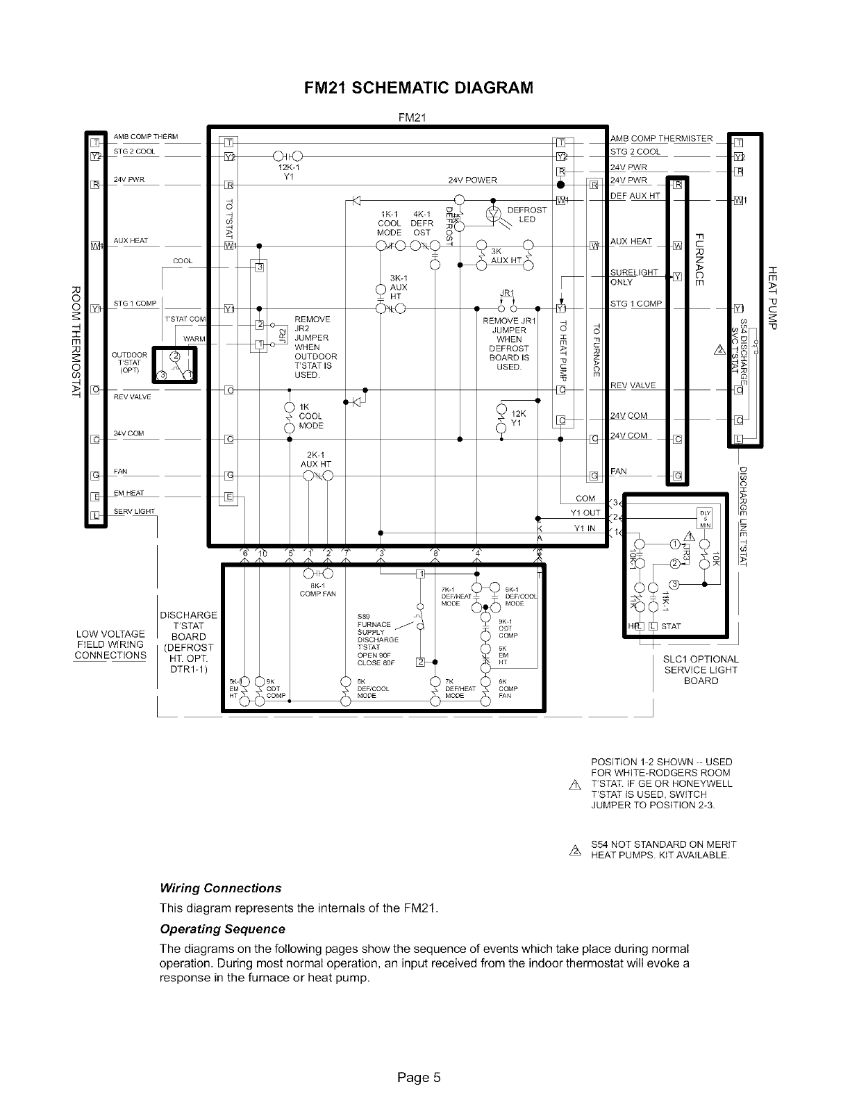
FM21 SCHEMATIC DIAGRAM
FM21
q_J
12Kq r_
Y1 24V POWER _
8 q4 _
-4 1K-1 4Kq mO4_ DEFROST
COOL DEFR _ LED
MODE OST 0 :_ [_
REMOVE
JR2
JUMPER
WHEN
OUTDOOR
T'STAT IS O>
USED. m
D []
ICOOL 12K
MODE
2K_1
AUX HT
COM
Y1 OUT
K Y1 IN
8K-1
COMP FAN
S89
FURNACE
SUPPLY
D]SCHARGE
T'STAT
OPEN 90F
CLOSE 80F
6K 8K
DEF/COOL COMP
MODE FAN
_,MB COMP THERMISTER
STG 2 COOL
24V PWR
[]
-N
[] c
;U
Z
>
[] o
m
A
[]
STAT
SLC1 OPTIONAL
SERVICE LIGHT
BOARD
POSITION 1-2 SHOWN - USED
FOR WHITE-RODGERS ROOM
Z_ T'STAT. tF GE OR HONEYWELL
T'STAT IS USED, SWITCH
JUMPER TO POSITION 2-3.
$54 NOT STANDARD ON MERIT
z_ HEAT PUMPS. KITAVAILABLE.
Wiring Connections
This diagram represents the internals of the FM21.
Operating Sequence
The diagrams on the following pages show the sequence of events which take place during normal
operation. During most normal operation, an input received from the indoor thermostat will evoke a
response in the furnace or heat pump.
Page 5

ALTERNATE ROOM THERMOSTAT JUMPERS AND WiRiNG CONNECTIONS TO FM21 CONTROL
"-0
Z_ MOST UNUSED THERMOSTAT TERMINALS NOT SHOWN.
z_ CONNECTION USED ONLY WITH HEAT
SERVICE LIGHT
PUMPS EQUIPPED WITH $54 SERVICE LIGHT T'STAT.
$54 AVAILABLE IN MONITOR KIT #76F53.
Z_ JR 3 SET FOR "WR TYR", SERVICE LIGHT ENERGIZED
WHEN 24VAC IS APPLIED TO T'STAT TERMINAL L.
AA
ELITE
THERMOSTAT
# 49M57
cc_
G O_
RO_
YI (_
Y2O_
Z_ EIW17( m,
43 w2"O
SIGNATURE
THERMOSTAT
# 51M28
cC)_--
G C)_--
RC)_--
Y/ O_--
Y20_--
w2'_ I
42)
-(3 L Q)@ --
HC_
DC_
OUTDOOR SENSOR, IF USED.
REQUIRES SEPARATE CABLE
FROM T'STAT TWISTED PAIR.
MIN. 22AWG, 300 FT. MAX.
Z_ THE FM21 OUTDOOR T'STAT & THE ROOM T'STAT
OUTDOOR SENSOR SHOULD NOT BOTH BE USED.
USE ONE OR THE OTHER. USE OF BOTH SENSORS
CREATES BALANCE POINT CONFLICT.
THE E INPUT OF THE FM21 IS USED ONLY WHEN A
Z_ DTRI _1 BOARD IS USED. THE E INPUT REQU IRES A
CONSTANT WRVAC INPUT DURING EMERGENCY HEAT MODE.
Z_ E,_Y1 OF THE THERMOSTAT IS THE 1ST STAGE OF
EMERGENCY HEA1L DO NOT CONNECT THE E INPUT
(OPTIONAL MANUAL SWITCH MAY BE WIRED FROM "R" TO "E")
W2 IS THE 1ST STAGE OF AUXIALARY HEAT JUMPER
z_ E,_YI TO W2.
A
$26
OUTDOOR
THERMOSTAT
z_(OPTIONAL)
DSL-450 #32M07
DSL-600 #13K97 L23 #91H73
24V _
Y2
RS20
RS+V
RS1
OUTDOOR SENSOR IF USED
REQUIRES SEPARATE 3-21RE
CABLE FROM T'STAT, 22AWG
MINIMUM, 300 FT. MAX.
T8611G 2101 TYPICAL ROOM
L22 #91H72 (2000 SERIES) THERMOSTAT
24VAC COMMON
INDOOR BLOWER
24VAC POWER
1ST STG COOL/HEAT
2ND STG COOL
AUXILIARY HEAT
REVERSING VALVE
AMBIENT SENSOR
EMERGENCY HEAT
SERVICE LIGHT
# 37L60
G _ G (_
R _ R ([_
(_ YI O
W1 YI Y20
w20 L w_ O
OlBC_ o O
T O
E CF_ E O
L_ L O
CHANGE T'STAT
FACTORY SETTING
INSTALLER SETUP
#29 FROM "0" TO "1"
TO ENERGIZE
REVERSING VALVE
O/B/TERMINAL IN
COOLING (sEE
T'STAT INSTALLATION
MANUAL).
TO HUMIDIFIER RELAY IF USED.
-- DEHUMIDIFICATION CONTROL, IF USED
CONNECT TO FURNACE DS ON VARIABLE
SPEED MODELS (REMOVE DS*R JUMPER).
THE ELITE & SIG. T'STATS AUTOMATICALLY TURN
ON THE BALANCE POINT FUNCTIONS WHEN THE
OUTDOOR SENSOR IS CONNECTED. THE ELITE &
SIG. T'STATS CANNOT READ THE OUTDOOR TEMP.
WITHOUT EMPLOYING THE BALANCE POINT
FUNCTION. IF DISPLAYING THE OUTDOOR TEMP. OR
USING OUTDOOR SENSOR FOR THE HUMIDITY
FUNCTION, THE FM21 $26 OUTDOOR THERMOSTAT
MUST NOT BE CONNECTED. (EUTE T'STAT DOES
NOT HAVE AN ADD HUMIDITY FUNCTION.)
DO NOT USE ELITE, SIG,, DSL T'STATS WITH FM21 WHEN
Z_ DEFROST HEAT OPTION MODULE tS USED ON FM21 (NO
EM, HT, 24V OUTPUT TERMINAL ON STAT).
I
O REMOVE JUMPER /
IsIFOUTDOORusEDSTAT/
OUTDOOR
THERMOSTAT
1 WARM 1
2COMMO
3 COOL
©
/
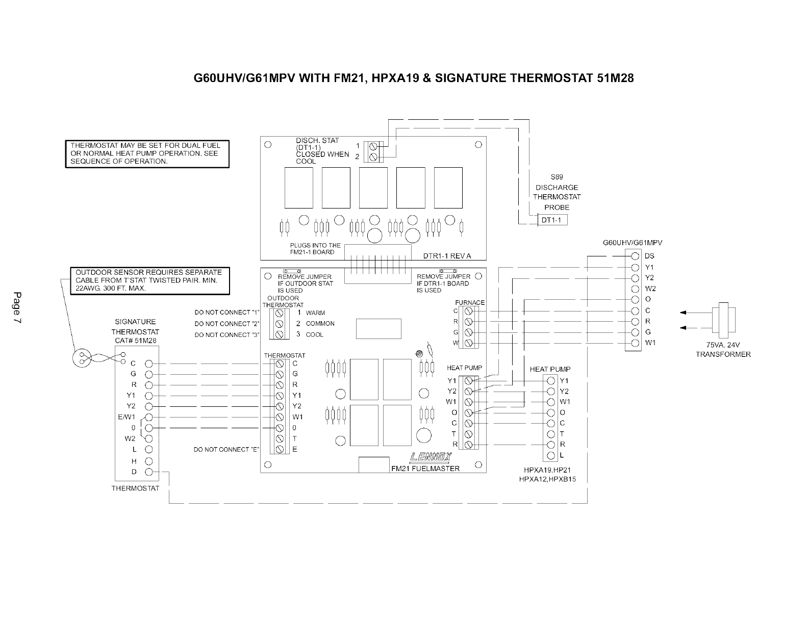
G60UHV/G61MPV WITH FM21, HPXA19 & SIGNATURE THERMOSTAT 51 M28
"-O
I THERMOSTAT MAY BE SET FOR DUAL FUEL
OR NORMAL HEAT PUMP OPERATION SEE
SEQUENCE OF OPERATION
OUTDOOR SENSOR REQUIRES SEPARATE
CABLE FROM T'STAT TWISTED PAIR. MIN.
22AWG 300 FT. MAX.
SIGNATURE
THERMOSTAT
CAT# 51 M28
DO NOT CONNECT "1'
DO NOT CONNECT "2'
DO NOT CONNECT "3'
THERMOSTAT
DO NOT CONNECT "E'
ODISCH. STAT
(DTI-1) 1
CLOSED WHEN 2
COOL
°000°000 000°0
PLUGS INTO THE /
FM21-I BOARD ] DTRI-1 REVA
O REMOVE JUMPER REMOVE JUMPER O
IFOUTDOOR STAT IFDTRI-1 BOARD
IS USED IS USED
OUTDOOR
THERMOSTAT FURNACE
1 WARM
2 COMMON
3 COOL
THERMOSTAT
_c
G
® R
_) Y1
Y2
Q Wl
@ 0
® T
@ E
O
_ HEAT PUMP
Y1
O Y2
W1
Q T
R
£Sb'H_Z
FM21 FUELMASTER O
$89
DISCHARGE
THERMOSTAT
I | PROBE
G60U HV/G61 MPV
_:D DS
@ Y1
W2
_o
_) C
__ R
_) Wl
HEAT PUMP
Y1
Y2
O Wl
4Do
©c
OT
OR
OL
HPXA19,HP21
HPXA12,HPXB15
75VA, 24V
TRANSFORMER
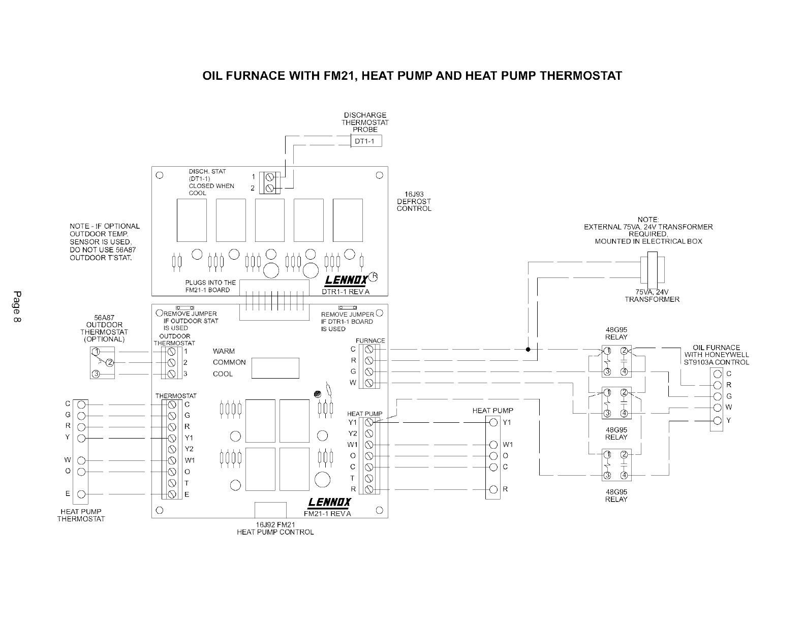
OIL FURNACE WITH FM21, HEAT PUMP AND HEAT PUMP THERMOSTAT
DISCHARGE
THERMOSTAT
PROBE
"0
NOTE - IF OPTIONAL
OUTDOOR TEMR
SENSOR tS USED,
DO NOT USE 56A87
OUTDOOR T'STAT.
56A87
OUTDOOR
THERMOSTAT
(OPTIONAL)
co
G O
R O
Y O
w@
o@
E©
HEAT PUMP
THERMOSTAT
ODISCH. STAT
(DT1-1) 1
CLOSED WHEN 2
COOL
00o 000o 000_
PLUGS INTOTHE F
FM2%1 BOARD
@REMOVE JUMPER
IF OUTDOOR STAT
IS USED
OUTDOOR
THERMOSTAT
WARM
COMMON
COOL
000°0
I.ENNDXO
DTRI-1 REVA
O
THERMOSTAT
c
Y1
Y2
w1
_o
T
@ E
©
REMOVE JUMPER O
IF DTR%l BOARD
IS USED
FURNACE
C
R
G
_ w
HEAT PUMP
Y2
O
Q
0000
© ©
0000 000
© © :
I_ENNDX
FM21-1 REVA
16J92 FM21
HEAT PUMP CONTROL
@
16J93
DEFROST
CONTROL
NOTE:
EXTERNAL 75VA, 24V TRANSFORMER
REQUIRED,
MOUNTED IN ELECTRICAL BOX
75VA, 24V
TRANSFORMER
F
JHEAT PUMP
@ Y1
_} wl
©o
©c
_) R
h48G95
RELAY
48G95
RELAY
OIL FURNACE
WITH HONEYWELL
ST9103A CONTROL
FM21 COOLING SEQUENCE -WITHOUT DEFROST OPTION
ii!!i_ii!_ iiliiiitj_
i!_ _¸ _b_
YI _'-- IST STAGE COOL/HEAT _YI
ooo
Operating Sequence -Cooling:
The diagram above shows the input and output signals in the
FM21. The following operating sequence steps through the in-
puts (left side of diagram) and the resulting outputs (right side
of diagram).
CONDITION:
With or Without Outdoor Thermostat
Constant Fan -Fan Switch "ON"
Blower (G) -Thin Black Line
1 - Blower demand from the thermostat passes directly through the
FM21 to energize the furnace blower on high speed.
CONDITION:
Cooling - Fan Switch "ON" or "AUTO"
Compressor (Y1) -Heavy Black Line
Reversing Valve (O) -Heavy Gray Line
1 - Reversing valve (O) is immediately energized when the indoor
thermostat is switched to cooling.
2 - On a call for first stage cooling (Y1 & G), indoor blower is ener-
gized on high speed and compressor is energized on low speed.
3 - Additional second stage cooling (Y2), compressor is energized on
high speed.
4 - Outdoor Thermostat (if used) has no effect on cooling.
Page 9
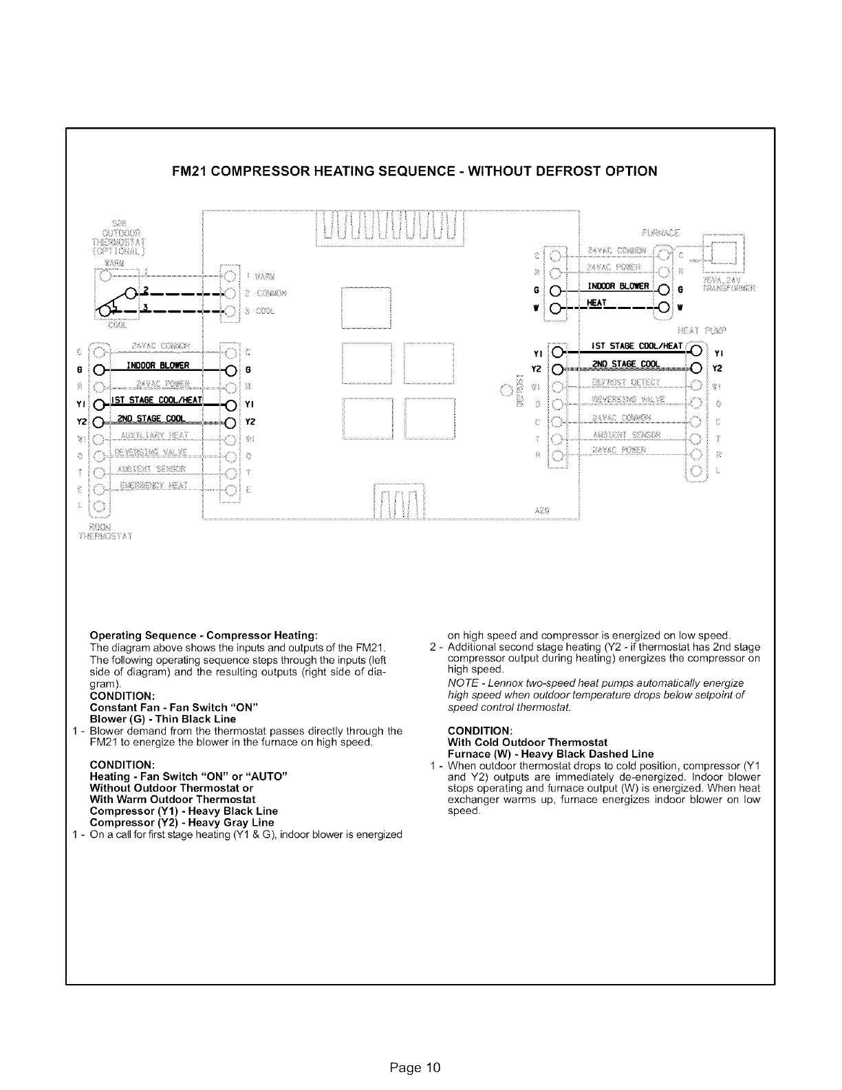
FM21 COMPRESSOR HEATING SEQUENCE - WITHOUT DEFROST OPTION
G(_- INDOORBLOWER
Y I _: ST STAGE COOL/Ia_AT
__ YI
,z
iiii!i
a
jii!ii_i!:i!!i_
CI::_¸'!
....:iii iiii !iii!iiiii:iiiiii!ii::: :ii iiiii!i
• .-o,...............
IST STAGE CO(]L/HEAT
Y2 _""""'i END STAGE COOL _y:_
Operating Sequence -Compressor Heating:
The diagram above shows the inputsand outputs of the FM21.
The following operating sequence steps through the inputs (left
side of diagram) and the resulting outputs (right side of dia-
gram).
CONDITION:
Constant Fan - Fan Switch "ON"
Blower (G) - Thin Black Line
1 - Blower demand from the thermostat passes directly through the
FM21 to energize the blower in the furnace on high speed.
CONDITION:
Heating - Fan Switch "ON" or "AUTO"
Without Outdoor Thermostat or
With Warm Outdoor Thermostat
Compressor (Y1) - Heavy Black Line
Compressor (Y2) - Heavy Gray Line
1 - On a call for first stage heating (Y1 & G), indoor blower is energized
2-
on high speed and compressor is energized on low speed.
Additional second stage heating (Y2 - if thermostat has 2nd stage
compressor output during heating) energizes the compressor on
high speed,
NOTE -Lennox two-speed heat pumps automatically energize
high speed when outdoor temperature drops below setpoint of
speed control thermostat.
CONDITION:
With Cold Outdoor Thermostat
Furnace (W) - Heavy Black Dashed Line
When outdoor thermostat drops to cold position, compressor (Y1
and Y2) outputs are immediately de-energized. Indoor blower
stops operating and furnace output (W) is energized. When heat
exchanger warms up, furnace energizes indoor blower on low
speed.
Page 10
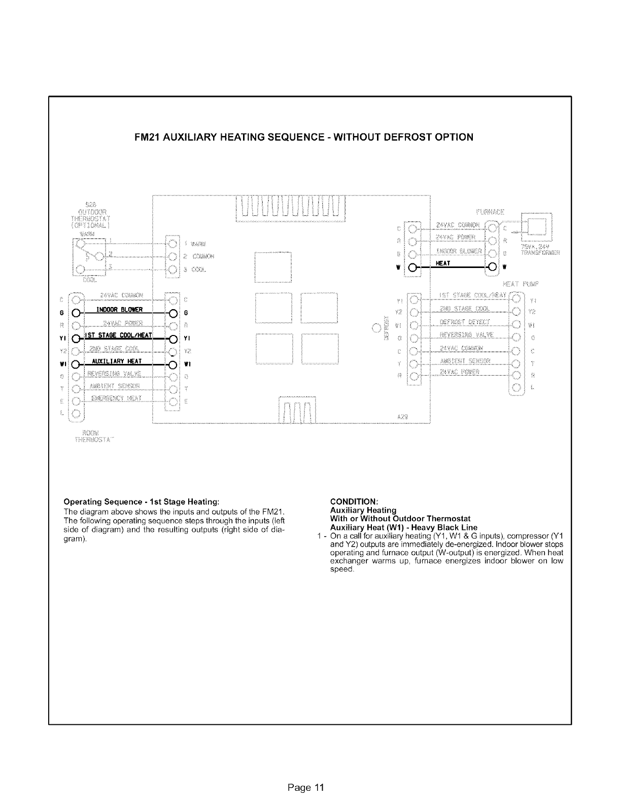
FM21 AUXILIARY HEATING SEQUENCE - WITHOUT DEFROST OPTION
;i:iii:iiiii_ii
Operating Sequence - 1st Stage Heating:
The diagram above shows the inputs and outputs of the FM21.
The following operating sequence steps through the inputs (left
side of diagram) and the resulting outputs (right side of dia-
gram).
CONDITION:
Auxiliary Heating
With or Without Outdoor Thermostat
Auxiliary Heat (Wl) - Heavy Black Line
1 - On a call for auxiliary heating (Y1, Wl & G inputs), compressor (Y1
and Y2) outputs are immediately de-energized. Indoor blower stops
operating and furnace output (W-output) is energized. When heat
exchanger warms up, furnace energizes indoor blower on low
speed.
Page 11
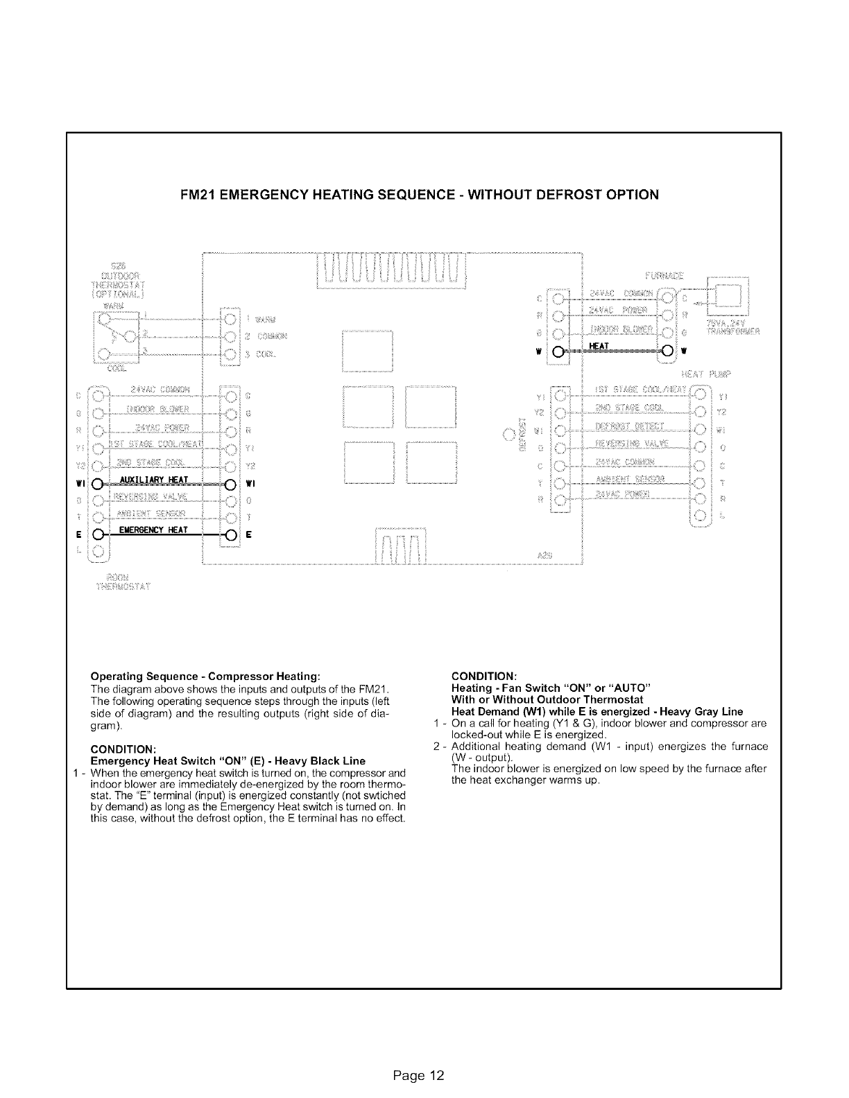
FM21 EMERGENCY HEATING SEQUENCE - WITHOUT DEFROST OPTION
i!i i i!iiiii ili ii iiiii,i iiiii !i:;;iiii ii:i I'I iiiiiiiiiiiiiiiii!i !
i ....................
I ...................................
Operating Sequence - Compressor Heating:
The diagram above shows the inputsand outputs of the FM21
The following operating sequence steps through the inputs (left
side of diagram) and the resulting outputs (right side of dia-
gram).
CONDITION:
Emergency Heat Switch "ON" (E) - Heavy Black Line
1 - When the emergency heat switch is turned on, the compressor and
indoor blower are immediately de-energized by the room thermo-
stat. The 'E" terminal (input) is energized constantly (not swtiched
by demand) as long as the Emergency Heat switch is turned on. In
this case, without the defrost option, the E terminal has no effect.
CONDITION:
Heating - Fan Switch "ON" or "AUTO"
With or Without Outdoor Thermostat
Heat Demand (Wl) while E is energized - Heavy Gray Line
1 - On a call for heating (Y1 & G), indoor blower and compressor are
locked-out while E is energized.
2- Additional heating demand (W1 - input) energizes the furnace
(W - output).
The indoor blower is energized on low speed by the furnace after
the heat exchanger warms up.
Page 12

FM21DEFROST SEQUENCE -WITHOUT DEFROST OPTION
!!Hii!iii;%ii,iH_iii_¸¸ii ii¸
i:
6
YI
Wl
0
ii:¸¸i!iii%HAi_ii!!!
ISTSTA_COOW_AT
YI YI
" o ''
Ji;;!%!}
Operating Sequence -Defrost:
The diagram above shows the inputs and outputs of the FM21.
The following operating sequence steps through the inputs (left
side of diagram) and the resulting outputs (right side of dia-
gram).
CONDITION:
Defrost Input (Wl) From Outdoor Unit - Heavy Gray Line
in conjunction with
Heating Demand (Y1 - input)
1 - When the FM21 senses a defrost cycle the defrost indicator LED is
energized.
2 - The compressor continues operating and the furnace is not ener-
gized (locked-out in order to prevent overheating the indoor coil).
Since the furnace is locked-out and indoor coil is cool, the indoor
thermostat may call for auxiliary (W1) heating during defrost.
3 - When defrost is complete, the furnace (W - output) will be ener-
gized to satisfy remaining thermostat demand.
1 -
CONDITION:
Defrost Input (Wl) From Outdoor Unit - Heavy Gray Line
in conjunction with
Auxiliary Heating Demand (Y1 and W1 - input)
Not possible since outdoor unit is de-energized during auxiliary
(W1 - input) heating.
Page 13
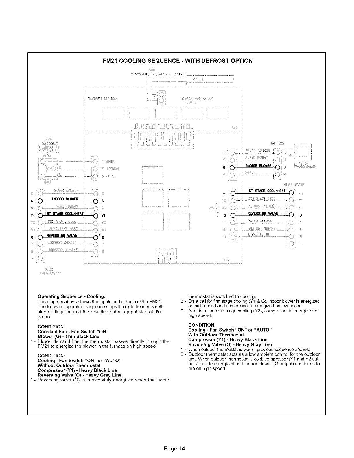
FM21COOLINGSEQUENCE-WITH DEFROST OPTION
i
_ i¸_oo_
oi:_i¸_0ill,i,
iiii_i:iili
i, ii
_=_i:ii;:;::iil]i_......:!!!!E_!i!!:!_!!Li!i!!:!_!!'!!_!!!!_!!i!!!!:L_,ii.__!iiiil;:::::(ii _:;
6
YI _ ST STAGE COOL/HEAT )
[ ??: : i
i iiili!i
ilil I=i i: iii=i:
I ST STA6E COOL/HEAT _ii
YI _YI
i ii!:i Iii;! i
Operating Sequence - Cooling:
The diagram above shows the inputs and outputs of the FM21.
The following operating sequence steps through the inputs (left
side of diagram) and the resulting outputs (right side of dia-
gram).
CONDITION:
Constant Fan -Fan Switch "ON"
Blower (G) - Thin Black Line
1 - Blower demand from the thermostat passes directly through the
FM21 to energize the blower in the furnace on high speed.
CONDITION:
Cooling - Fan Switch "ON" or "AUTO"
Without Outdoor Thermostat
Compressor (Y1) - Heavy Black Line
Reversing Valve (O) - Heavy Gray Line
1 - Reversing valve (O) is immediately energized when the indoor
thermostat is switched to cooling.
2 - On a call for first stage cooling (Y1 & G), indoor blower is energized
on high speed and compressor is energized on low speed.
3 - Additional second stage cooling (Y2), compressor is energized on
high speed.
1 -
2-
CONDITION:
Cooling - Fan Switch "ON" or "AUTO"
With Outdoor Thermostat
Compressor (Y1) - Heavy Black Line
Reversing Valve (O) - Heavy Gray Line
When outdoor thermostat is warm, previous sequence applies,
Outdoor thermostat acts as a low ambient control for the outdoor
unit, When outdoor thermostat is cold, compressor (Y1 and Y2 out-
puts) are de-energized and indoor blower (G output) continues to
run on high speed.
Page 14
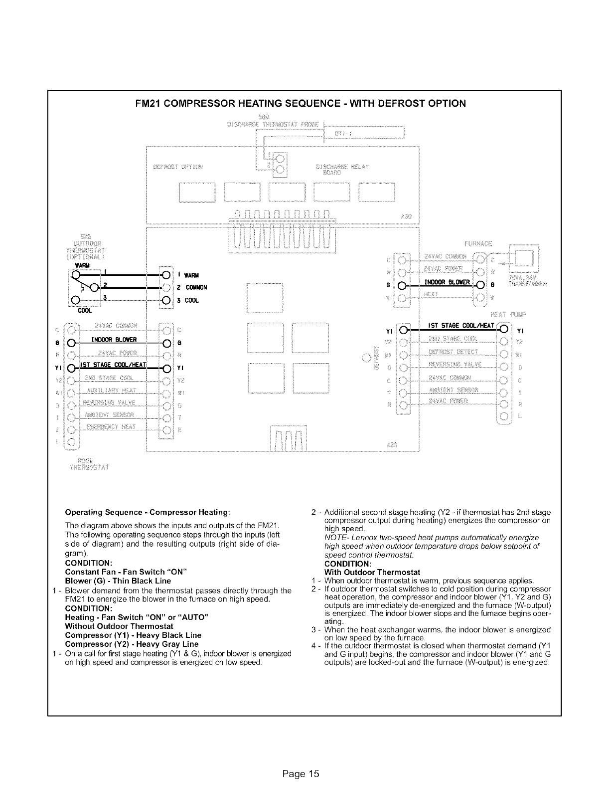
FM21 COMPRESSOR HEATING SEQUENCE - WITH DEFROST OPTION
WARM
COOL
' !!ii!,
2 COMMON
3cool
ii:il
y ST STA6E COOL/HEAT
ii................................ii
YI IST STAGE COQ./HEAT YI
Operating Sequence - Compressor Heating: 2-
The diagram above shows the inputs and outputs of the FM21.
The following operating sequence steps through the inputs (left
side of diagram) and the resulting outputs (right side of dia-
gram).
CONDITION:
Constant Fan -Fan Switch "ON"
Blower (G) - Thin Black Line 1-
1 - Blower demand from the thermostat passes directly through the 2 -
FM21 to energize the blower in the furnace on high speed.
CONDITION:
Heating -Fan Switch "ON" or "AUTO"
Without Outdoor Thermostat 3 -
Compressor (Y1) - Heavy Black Line
Compressor (Y2) - Heavy Gray Line 4 -
1 - On a call for first stage heating (Y1 & G), indoor blower is energized
on high speed and compressor is energized on low speed.
Additional second stage heating (Y2 - if thermostat has 2nd stage
compressor output during heating) energizes the compressor on
high speed.
NOTE- Lennox two-speed heat pumps automatically energize
high speed when outdoor temperature drops below setpoint of
speed control thermostat.
CONDITION:
With Outdoor Thermostat
When outdoor thermostat is warm, previous sequence applies.
If outdoor thermostat switches to cold position during compressor
heat operation, the compressor and indoor blower (Y1, Y2 and G)
outputs are immediately de-energized and the furnace (W-output)
is energized. The indoor blower stops and the fumace begins oper-
ating.
When the heat exchanger warms, the indoor blower is energized
on low speed by the furnace.
If the outdoor thermostat is closed when thermostat demand (Y1
and G input) begins, the compressor and indoor blower (Y1 and G
outputs) are locked-out and the furnace (W-output) is energized.
Page 15
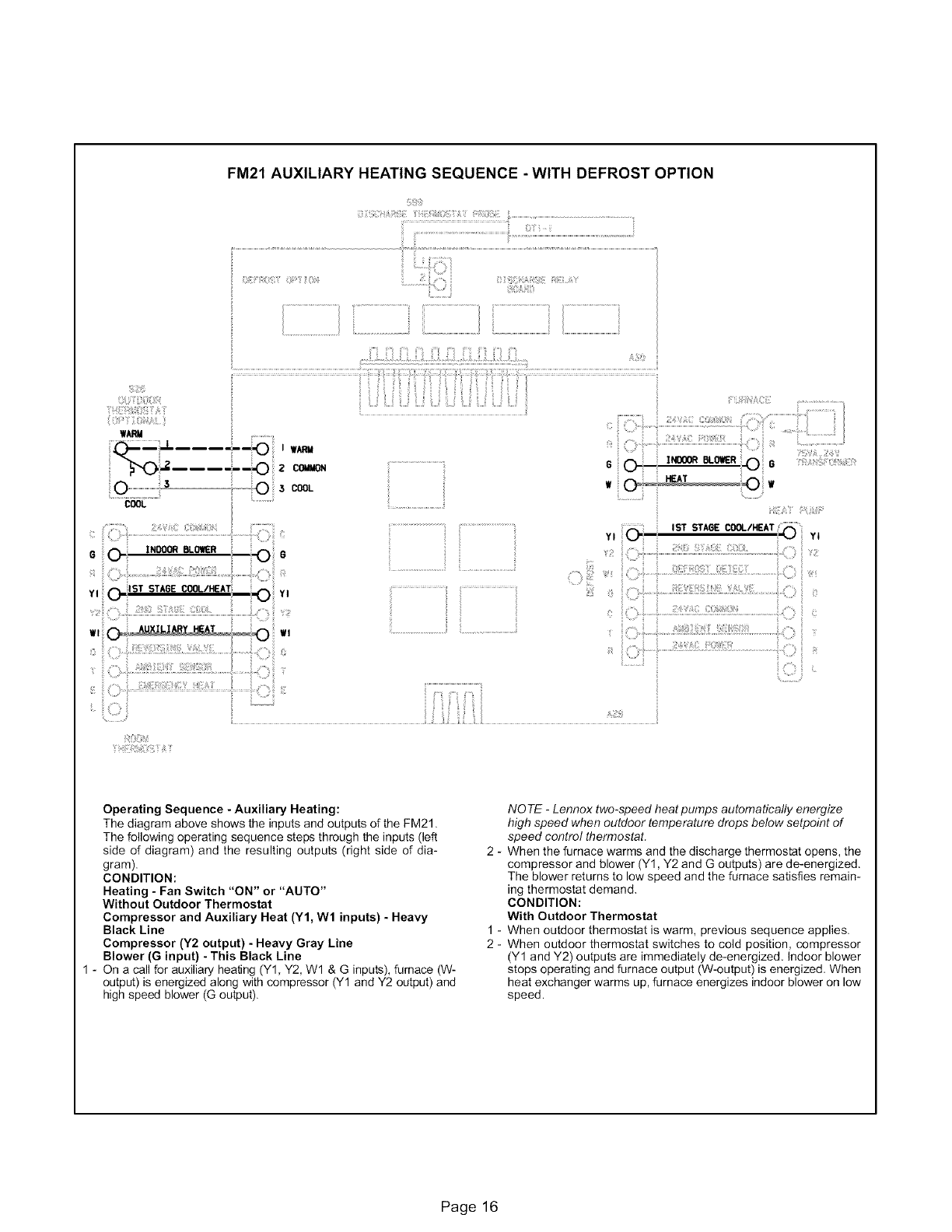
FM21 AUXILIARY HEATING SEQUENCE - WITH DEFROST OPTION
i ..................................................................
6
sTSTA_ECOOL/HEAT
Yl YJ
Operating Sequence -Auxiliary Heating:
The diagram above shows the inputsand outputs of the FM21,
The following operating sequence steps through the inputs (left
side of diagram) and the resulting outputs (right side of dia-
gram).
CONDITION:
Heating - Fan Switch "ON" or "AUTO"
Without Outdoor Thermostat
Compressor and Auxiliary Heat (Y1, Wl inputs} - Heavy
Black Line
Compressor (Y2 output) -Heavy Gray Line
Blower (G input) -This Black Line
1 - On a call for auxiliary heating (Y1, Y2, W1 & G inputs), furnace (W-
output) is energized along with compressor (Y1 and Y2 output) and
high speed blower (G output).
NOTE -Lennox two-speed heat pumps automatically energize
high speed when outdoor temperature drops below setpoint of
speed control thermostat.
2 - When the furnace warms and the discharge thermostat opens, the
compressor and blower (Y1, Y2 and G outputs) are de-energized.
The blower returns to low speed and the furnace satisfies remain-
ing thermostat demand.
CONDITION:
With Outdoor Thermostat
1 - When outdoor thermostat is warm, previous sequence applies.
2 - When outdoor thermostat switches to cold position, compressor
(Y1 and Y2) outputs are immediately de-energized. Indoor blower
stops operating and furnace output (W-output) is energized. When
heat exchanger warms up, furnace energizes indoor blower on low
speed.
Page 16
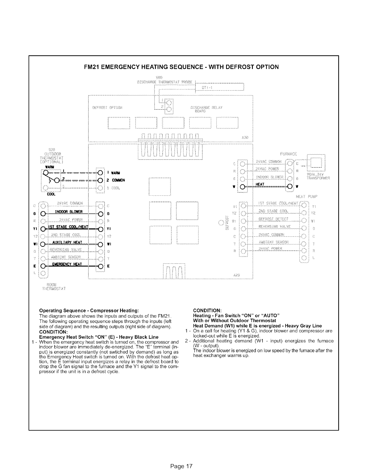
FM21 EMERGENCY HEATING SEQUENCE - WITH DEFROST OPTION
iJilit!_iiii_i_;;_ii;!_iilii_i:i!_:ili_ii_!iiiii_ii¸ i:_i_i_i_i_X!!!i_:_il.............................................................................
...................................................... ii
.... z co .
...............................................................................................
iili!i!iii
Operating Sequence - Compressor Heating:
The diagram above shows the inputs and outputs of the FM21.
The following operating sequence steps through the inputs (left
side of diagram) and the resulting outputs (right side of diagram).
CONDITION:
Emergency Heat Switch "ON" (E) - Heavy Black Line
1 - When the emergency heat switch is turned on, the compressor and
indoor blower are immediately de-energized. The "E" terminal (in-
put) is energized constantly (not swtiched by demand) as long as
the Emergency Heat switch is turned on. With the defrost heat op-
tion, the E terminal input energizes a relay in the defrost board to
drop the G fan signal to the furnace and the Y1 signal to the com-
pressor if the unit is in a defrost cycle.
CONDITION:
Heating - Fan Switch "ON" or "AUTO"
With or Without Outdoor Thermostat
Heat Demand (Wl) while E is energized - Heavy Gray Line
1 - On a call for heating (Y1 & G), indoor blower and compressor are
locked-out while E is energized.
2- Additional heating demand (W1 - input) energizes the furnace
(W - output).
The indoor blower is energized on low speed by the furnace after the
heat exchanger warms up.
Page 17
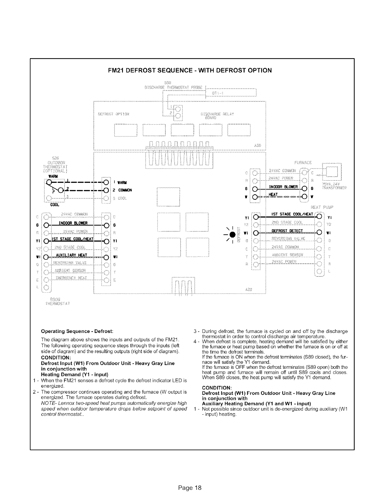
FM21DEFROST SEQUENCE -WITH DEFROST OPTION
y_/_ii_ _i¸¸
WARM
:!
YI _ Isx STA6E_OL/_AT YI
>
:iii , ,,iiii iii iiiii '
w _o_ .... _ w
_STSTAeeCOOL,_A__
YI i, i i i yi
i
Operating Sequence -Defrost: 3 -
The diagram above shows the inputs and outputs of the FM21. 4 -
The following operating sequence steps through the inputs (left
side of diagram) and the resulting outputs (right side of diagram).
CONDITION:
Defrost Input (Wl) From Outdoor Unit - Heavy Gray Line
in conjunction with
Heating Demand (Y1 - input)
1 - When the FM21 senses a defrost cycle the defrost indicator LED is
energized.
2 - The compressor continues operating and the furnace (W output is
energized. The furnace operates during defrost.
NOTE- Lennox two-speed heat pumps automatically energize high
speed when outdoor temperature drops below setpoint of speed 1 -
control thermostat..
During defrost, the furnace is cycled on and off by the discharge
thermostat in order to control discharge air temperature.
When defrost is complete, heating demand will be satisfied by either
the furnace or heat pump based on whether the furnace is on or off at
the time the defrost terminals.
If the furnace is ON when the defrost terminates ($89 closed), the fur-
nace will satisfy the Y1 demand.
If the fumace is OFF when the defrost terminates ($89 open) both the
heat pump and furnace will remain off until $89 cools and closes.
When $89 closes, the heat pump will satisfy the Y1 demand.
CONDITION:
Defrost Input (Wl) From Outdoor Unit - Heavy Gray Line
in conjunction with
Auxiliary Heating Demand (Y1 and W1 - input)
Not possible since outdoor unit is de-energized during auxiliary (Wl
- input) heating.
Page 18
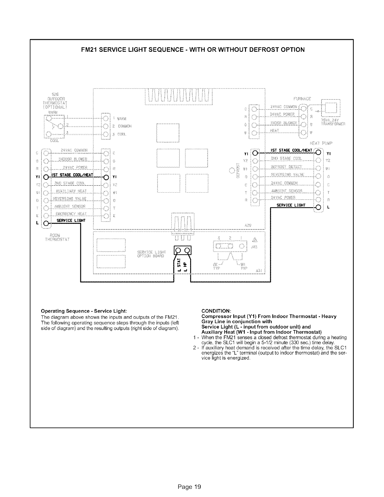
FM21SERVICELIGHT SEQUENCE -WITH OR WITHOUT DEFROST OPTION
!"!£_i_©___i¸
i i_ ¸_0_i !
L
iii ..................................
..................................iil
!iI................................!i_ ii_.................................
_i!_:_i_!i[i];iiii!!ii:!_ii_ii_!i_i_¸
v,............._ ,sTSTA,_C_,_AT V,
iii!!!i i: iii:
Operating Sequence -Service Light:
The diagram above shows the inputs and outputs of the FM21.
The following operating sequence steps through the inputs (left
side of diagram) and the resulting outputs (right side of diagram).
CONDITION:
Compressor Input (Y1) From Indoor Thermostat - Heavy
Gray Line in conjunction with
Service Light (L -input from outdoor unit) and
Auxiliary Heat (W1 -Input from Indoor Thermostat)
1 - When the FM21 senses a closed defrost thermostat during a heating
cycle, the SLCl will begin a 5-1/2 minute (330 sec.) time delay.
2 - If auxiliary heat demand is received after the time delay, the SLCl
energizes the 'L" terminal (output to indoor thermostat) and the ser-
vice light is energized.
Page 19
I[o]_l[o_[o_l
[o_J [o_
[o_J _1
"U
c,Q
cD
o
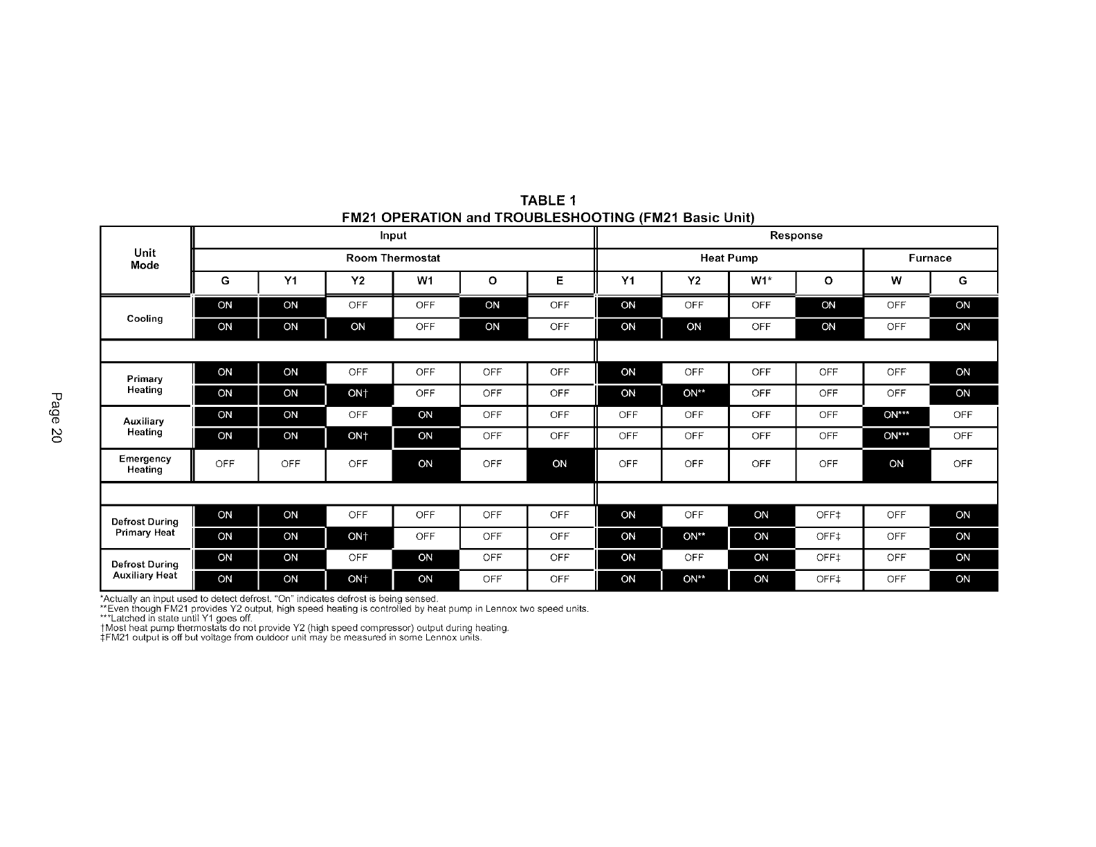
TABLE 1
FM21 OPERATION and TROUBLESHOOTING (FM21 Basic Unit)
Input
Unit Room Thermostat
Mode
G I Y1 Y2 Wl I O Y1 G
OFF OFF
Primary
Heating
Auxiliary
Heating
Emergency
Heating
OFF OFF
OFF
OFF
OFF
OFF
OFF
OFF
OFF
OFF
E
OFF
OFF
OFF I[o]_l[o_J _J
OFF
OFF
OFF
OFF
OFF
OFF OFF OFF
OFF OFF OFF
OFF OFF I[o]_l[o]_l
[o_ )_1 D_ii OFF
Defrost During
Primary Heat
Defrost During
I[o]_l
*Actually an input used to detect defrost, "On" indicates defrost is bein_ sensed.
**Even though FM21 provides Y2 output, high speed heating is controlled by heat pump in Lennox two speed units.
***Latched in state until Y1 goes off.
tMost heat pump thermostats do not provide Y2 (high speed compressor) output during heating.
$FM21 output is off but voltage from outdoor unit may be measured in some Lennox units.
Response
Heat Pump
Y2 W1 *O
OFF OFF
OFF
OFF
OFF
OFF
OFF
OFF
OFF
OFF
OFF
OFF
OFF
OFF
OFF
OFF
OFF
OFF
OFF
OFF
OFF
Furnace
W
OFF
OFF
OFF
OFF
OFF$ OFF
OFF$ OFF
OFF$ OFF
OFF$ OFF
OFF
OFF
OFF
[o_o_.']_l_
"U
c,Q
cD
Unit
Mode G I
Cooling
Primary
Heating
Auxiliary
Heating
Emergency
Heating
Defrost During
Primary Heat
Defrost During
Auxiliary Heat
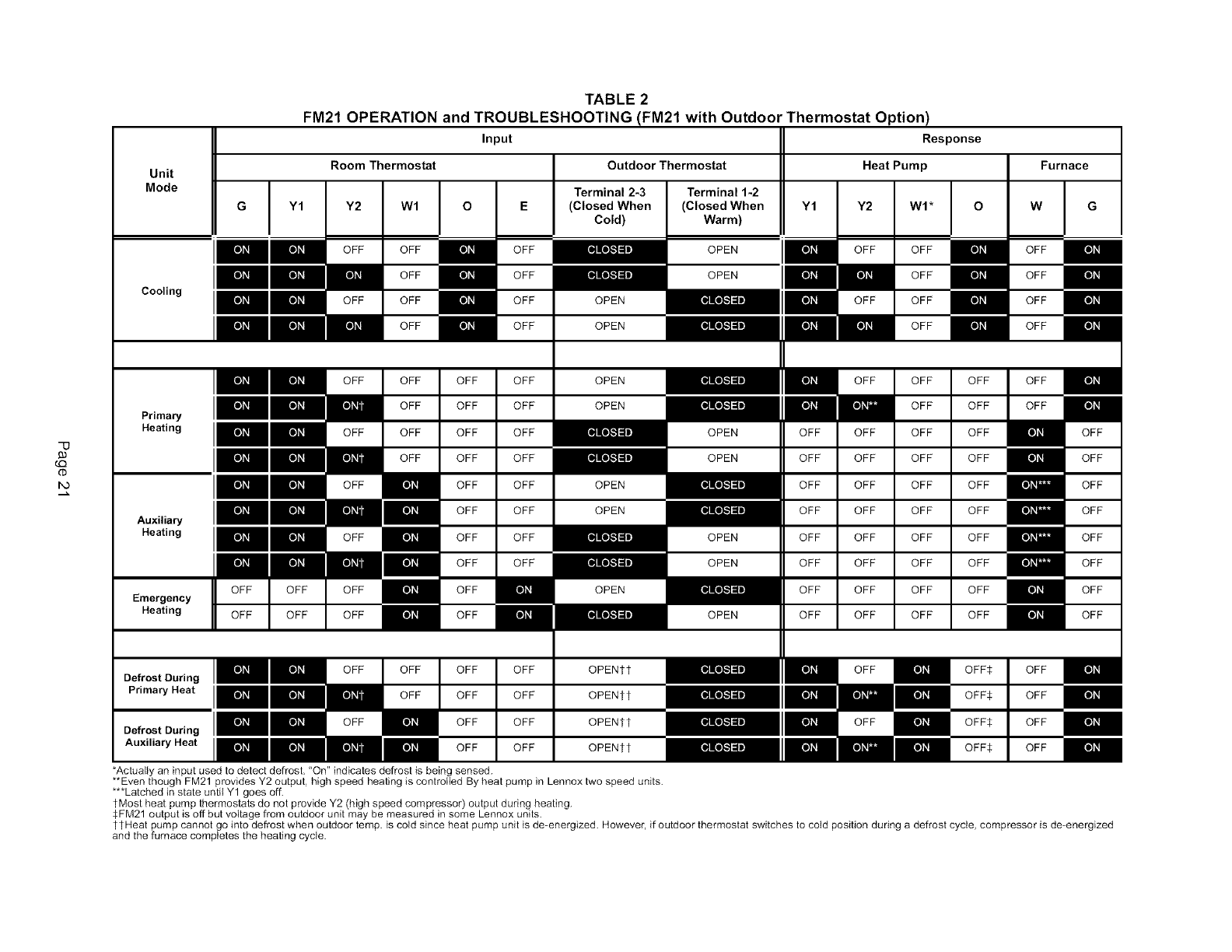
FM21 OPERATION TABLE 2
and TROUBLESHOOTING (FM21 with Outdoor Thermostat Option)
Input Response
Room Thermostat Outdoor Thermostat Heat Pump Furnace
Terminal 2-3 Terminal 1-2
E (Closed When (Closed When Y2
Cold) Warm)
Y1 Y2 W1
OFF OFF
im--
OFF OFF
OFF
OFF
OFF
OFF
OFF
OFF OFF
OFF OFF
OFF OFF
OFF OFF
OFF OFF
OFF OFF
OFF OFF
OFF OFF
OFF
OFF
*Actually an input used to detect defrost. "On" indicates defrost is being sensed.
OPEN
OPEN
OPEN
OPEN
OFF
OPEN
OPEN
OPEN
OPENtt
OPENtt
OPENtt
OPENtt
H
OFF
OPEN
OFF
OFF
OFF
OFF
OFF
OFF
OFF
OFF
OFF
OFF
OFF
OFF
OFF
OFF
OFF
OFF
OFF
OFF
OFF
OFF
OFF
OFF
OFF
OFF OFF
OFF OFF
OFF OFF
OFF OFF
OFF OFF
OFF OFF
**Even though FM21 provides Y2 output high speed heating is controlled By heat pump in Lennox two speed units.
***Latched in state until Y1 goes off.
tMost heat pump thermostats do not provide Y2 (high speed compressor) output during heating.
$FM21 output is off but voltage from outdoor unit may be measured in some Lennox units.
tSHeat pump cannot go into defrost when outdoor temp. is cold since heat pump unit is de-energized. However, if outdoor thermostat switches to cold position during a defrost cycle, compressor is de-energized
and the furnace completes the heating cycle.
Eo]_l[o_J[o]J_l
[o]_J[o_J[o_l
[o_l[o_J[o_l
[o_J [o_J[o_l
[o_l Eo]J_l
[o]_o_.']_l_ [o]_,J [o]_r-_J [o]_J
[o]_J
[o]_J
[o]_o_.']_l_ [o]_,J [o]_r-_J
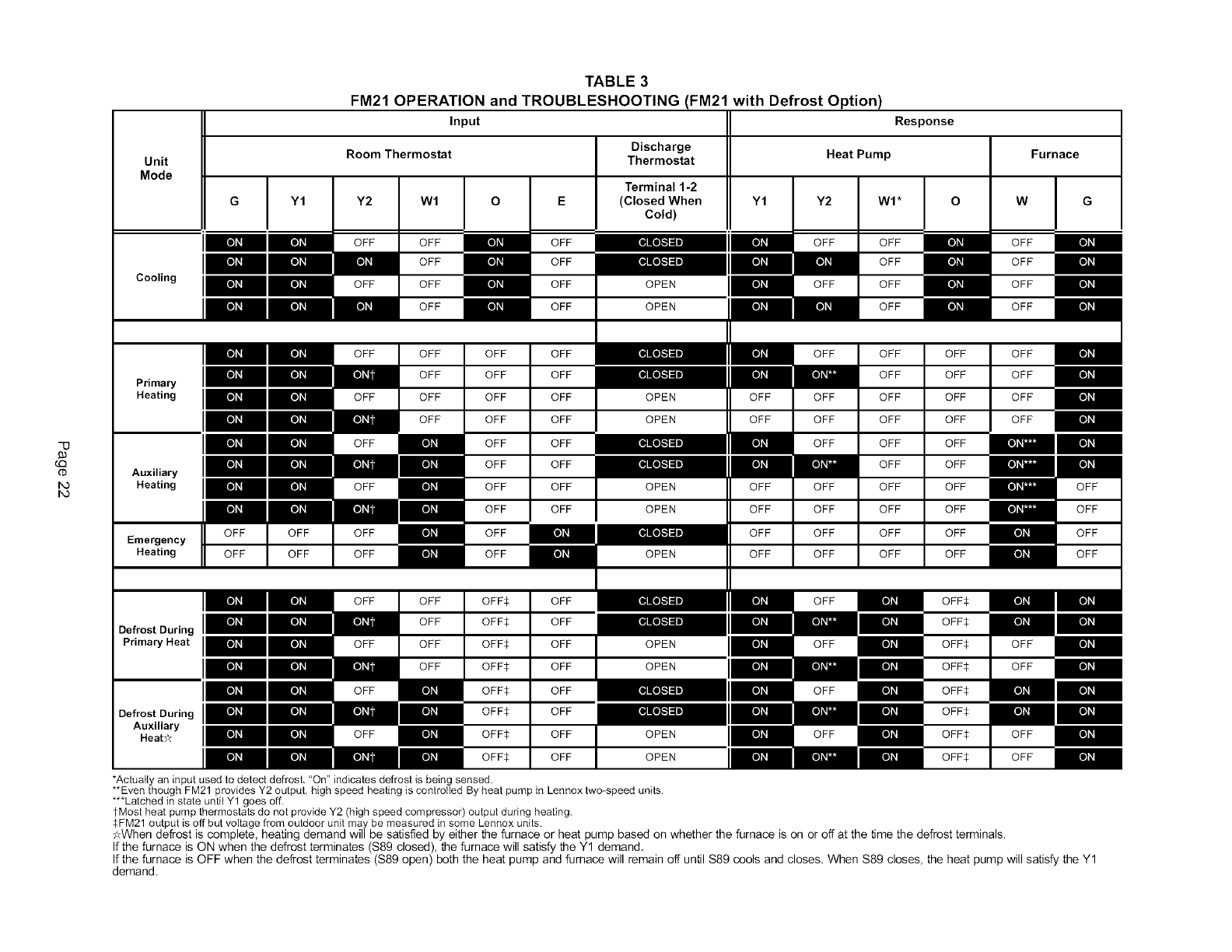
TABLE 3
FM21 OPERATION and TROUBLESHOOTING (FM21 with Defrost Option)
Input Response
Room Thermostat Discharge Heat Pump
Unit Thermostat
Mode
Cooling
Primary
Heating
Auxiliary
Heating
Emergency
Heating
Y1 Y2 Wl
OFF OFF
[o_J OFF
OFF OFF
OFF
OFF OFF
OFF
OFF OFF
OFF
[o_OFF
OFF
OFF
OFF OFF
[o_
[o]_|.....
_1]11
[o]_J [o]_J
[o]_J [o]_J
E_o_ [o]_J Eo]_J
[o]_J Eo]_J
Defrost During INN
Primary Heat IHH
OFF
OFF
OFF
OFF
OFF
OFF
OFF
OFF
OFF
OFF
OFF OFF OFF$
OFF OFF$
OFF OFF OFF$
OFF OFF$ [o]_J
[o]_J[o_
OFF OFF$
OFF$
[o_
[o_
OFF OFF$
OFF$
[o]_J
[o]_J
Oe,roatOaringINN
Auxiliary
Heat:_
OFF
OFF
OFF
OFF
OFF
OFF
OFF
OFF
OFF
OFF
OFF
OFF
Terminal 1-2
(Closed When
Cold)
OPEN
OPEN
OPEN
OPEN
OPEN
OPEN
[o]_J
[o]_J
[o]_J
*Actually an input used to detect defrost. "On" indicates defrost is being sensed.
OFF
OFF
OFF
OFF
OFF
OFF
OFF
OFF
**Even though FM21 provides Y2 output, high speed heating is controlled By heat pump in Lennox two-speed units.
***Latched in state until Y1 goes off.
tMost heat pump thermostats do not provide Y2 (high speed compressor) output during heating.
$FM21 output is off but voltage from outdoor unit may be measured in some Lennox units.
OPEN
OPEN
OPEN
Y1
OFF
OFF
OFF
OFF
OFF
OFF
Y2 WI*
OFF OFF
OFF
OFF
OFF
OFF OFF
OFF
OFF OFF
OFF OFF
OFF OFF
OFF
OFF OFF
OFF OFF
OFF OFF
OFF OFF
OFF
OFF
OFF
OFF
Furnace
O W
OFF
OFF
OFF
OFF
OFF OFF
OFF OFF
OFF OFF
OFF OFF
OFF
OFF
OFF
OFF
OFF
OFF$
OFF$
OFF$ OFF
OFF$ OFF
OFF$
OFF$
OFF$ OFF
OFF$ OFF
OFF
OFF
OFF
OFF
¢_-Whendefrost is complete, heating demand will be satisfied by either the furnace or heat pump based on whether the furnace is on or off at the _me the defrost terminals.
If the furnace is ON when the defrost terminates (S89 closed), the furnace will satisfy the Y1 demand.
If the furnace is OFF when the defrost terminates (S89 open) both the heat pump and furnace will remain off until S89 cools and closes. When S89 closes, the heat pump will satisfy the Y1
demand.
Eo]II[o_JEo]_J
Eo]_J[o_JEo_l
Eo_l[o_JEo_l
[o_J Eo_I
[o_l Eo]_J
"0
c,Q
cD
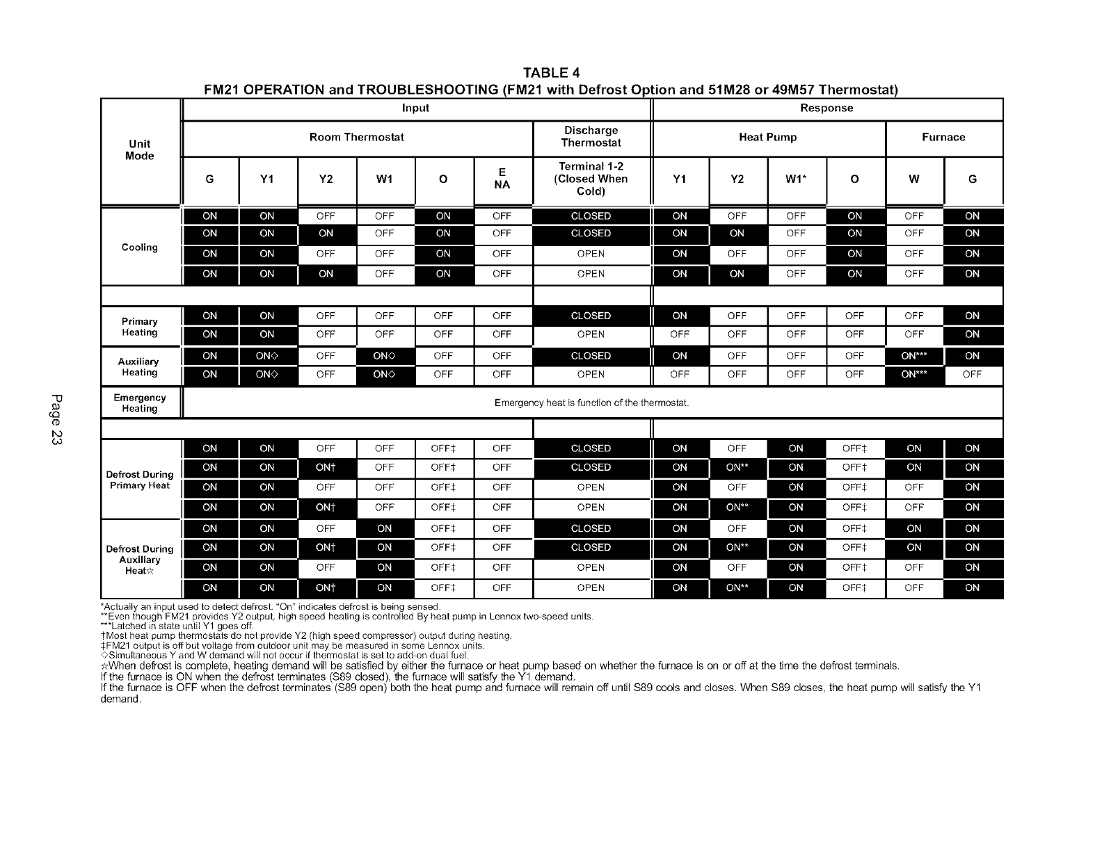
TABLE 4
FM21 OPERATION and TROUBLESHOOTING (FM21 with Defrost Option and 51M28 or 49M57 Thermostat)
Input Response
Room Thermostat Discharge Heat Pump Furnace
Unit Thermostat
Mode
Cooling
Primary
Heating
Auxiliary
Heating
Emergency
Heating
G Y1
[o_l Eo]_J
Defrost During INN
Primary Heat IHH
Y2 Wl
OFF OFF
[o_J OFF
OFF OFF
OFF
E
NA
OFF OFF
OFF OFF
OFF
Terminal 1-2
(Closed When
Cold)
OPEN
OPEN
OFF
OFF
OFF
OFF
OFF OFF OFF¢
OFF OFF$
OFF OFF OFF$
OFF OFF$ Eo]_J
Eo]_J[o_OFF OFF$
OFF$
[o_
[o_
OFF OFF$
OFF$
Eo]_J
Eo]J_l
Oe,roetOaringINN
Auxiliary
HeatY_
OFF
OFF
OFF
OFF
OFF
OFF
OFF
OFF
OPEN
OPEN
Y1
OFF
OFF
Emergency heat is function of the thermostat.
OPEN
OPEN
Eo]_J
Eo]J_lOPEN
OFF
OFF
OFF
OFF
OFF
OFF
OFF
OFF Eo]ll
*Actually an input used to detect defrost, "On" indicates defrost is being sensed.
**Even though FM21 provides Y2 output, high speed heating is controlled By heat pump in Lennox two-speed units.
***Latched in state until Y1 goes off.
tMost heat pump thermostats do not provide Y2 (high speed compressor) output during heating.
$FM21 output is off but voltage from outdoor unit may be measured in some Lennox units.
<>Simultaneous Y and W demand will not occur if thermostat is set to add-on dual fuel.
Y2 WI* O
OFF OFF
OFF
OFF OFF
OFF
OFF OFF OFF
OFF OFF OFF
OFF OFF OFF
OFF OFF OFF
Eo]_J
Eo]_J
Eo]J_l
Eo]_J
Eo]_J
Eo]_J
Eo]J_l
Eo]_J
OFF OFF$
OFF$
OFF OFF$
OFF$
OFF OFF$
OFF$
OFF OFF$
OFF$
W
OFF
OFF
OFF
OFF
OFF
OFF
OFF
€_-Whendefrost is complete, heating demand will be satisfied by either the furnace or heat pump based on whether the furnace is on or off at the time the defrost terminals.
If the furnace is ON when the defrost terminates (S89 closed), the furnace will satisfy the Y1 demand.
If the furnace is OFF when the defrost terminates (S89 open) both the heat pump and furnace will remain off until S89 cools and closes. When S89 closes, the heat pump will satisfy the Y1
demand.
"0
Unit11
Mode
G Y1
Cooling
Primary
Heating
Auxiliary
Heating
Emergen-
cy
Heating
Defrost
During
Primary
Heat
Defrost
During
Auxiliary
Heat_<
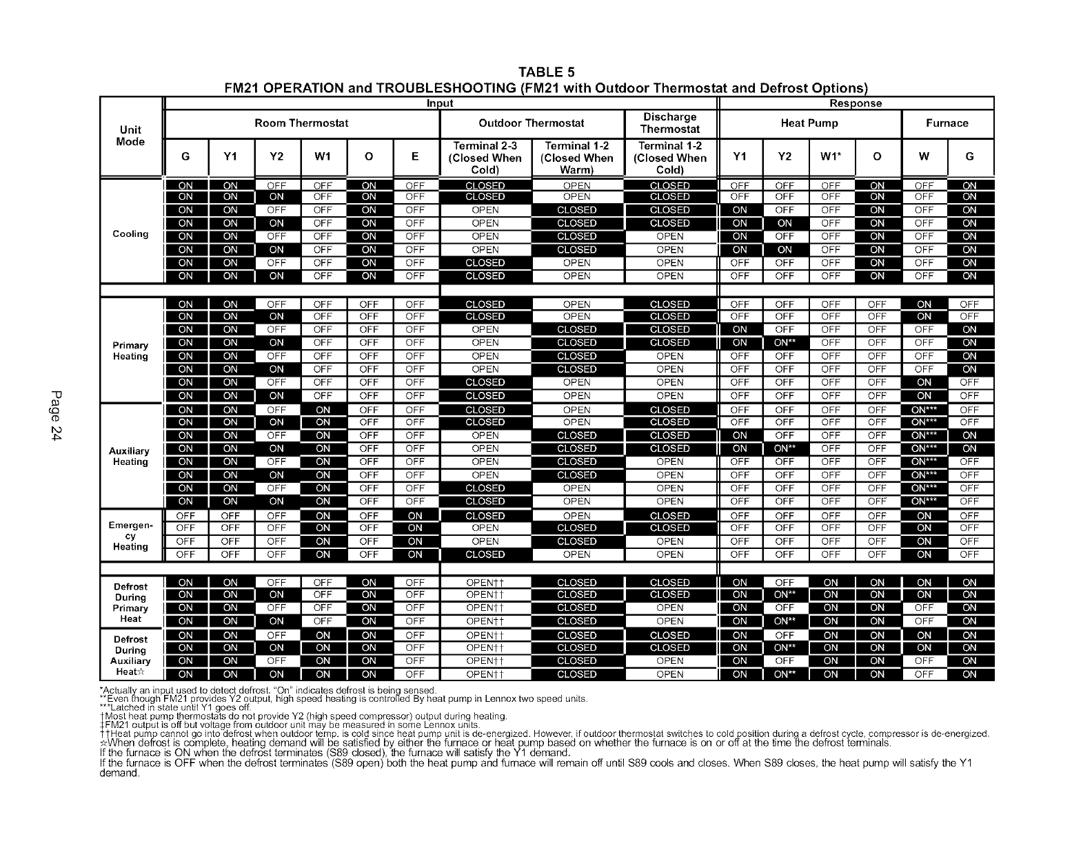
TABLE 5
FM21 OPERATION and TROUBLESHOOTING (FM21 with Outdoor Thermostat and Defrost Options)
Inl,ut
Room Thermostat Outdoor Thermostat I DischargeThermostat
Terminal 2-3 Terminal 1-2 Terminal 1-2
(Closed When (Closed When (Closed When Y1 Y2
Cold) Warm[ Cold)
OPEN OFF OFF
OPEN OFF OFF
OPEN OFF
OPEN
OPEN OPEN OFF
OPEN OPEN
OPEN OPEN OFF
OPEN OPEN OFF
OPEN
OPEN
OPEN
OPEN
OPEN
OPEN
OPEN
OPEN
OPEN
OPEN
OPENer
OPENtt
OPENtt
OPENtt
OPENtt
OPENtt
OPENtt
OPENtt
OPEN
OPEN
OPEN
OPEN
OPEN
OPEN
OPEN
OPEN
OPEN
OPEN
OPEN
OPEN
OPEN
OPEN
OPEN
OPEN
OPEN
Response
Heat Pump
OPEN
OPEN OPEN
OPEN
OPEN
OPEN
OPEN
Furnace
*Actually/an input used to detect defrost. "On" indicates defrost is bein 9sensed.
**Even mough FM21 provides Y2 output, high speed heating is controued By heat pump in Lennox two speed units.
***Latched in state untiI Y1 goes off.
tMost heat pump thermostats do not provide Y2 (high speed compressor) output durin 9heating.
$FM21 output is off but voltage from outdoor unit may be measured in some Lennox units.
ttHeat pump cannot go into defrost when outdoor temp. is cold since heat pump unit is de-energized. However, if outdoor thermostat switches to cotdposition during a defrost cycle, compressor is de-energized.
_-When defrost is complete, heating demand will be satisfied by either the furnace or heat pump based on whether the furnace is on or off.at the time the defrost terminals.
If the furnace is ON when the defrost terminates (S89 closed), the furnace will satisfy the Y1 demand.
If the furnace is OFF when the defrost terminates ($89 open) both the heat pump and furnace will remain off. un_l S89 cools and closes. When $89 closes, the heat pump will satisfy the Y1
demand.
