LENNOX Furnace/Heater, Oil Manual L0806376
User Manual: LENNOX LENNOX Furnace/Heater, Oil Manual LENNOX Furnace/Heater, Oil Owner's Manual, LENNOX Furnace/Heater, Oil installation guides
Open the PDF directly: View PDF ![]() .
.
Page Count: 23
LENNOX
'_ 2002 Lennox industries inc.
Dallas, Texas, USA
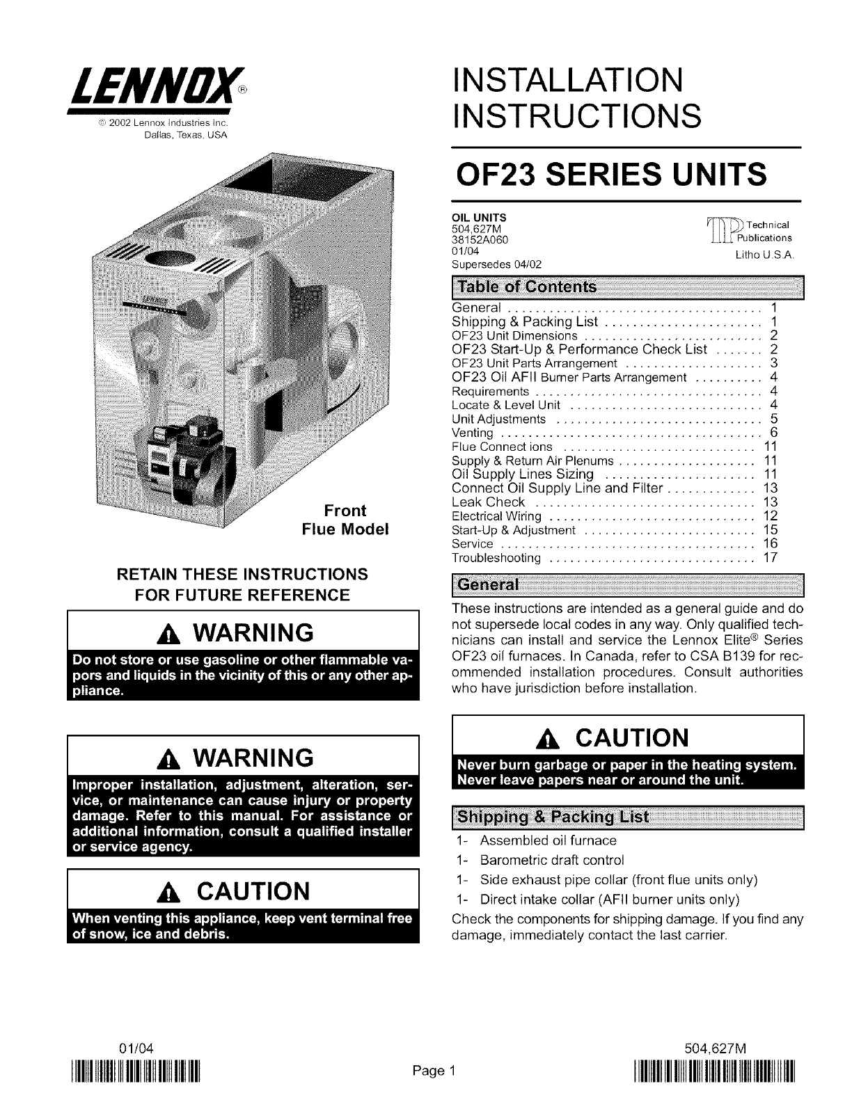
INSTALLATION
INSTRUCTIONS
OF23 SERIES UNITS
OIL UNITS _-_--_ Technical
504,627M
38152A060 ,LLL_ Publications
01/04 Lithe U.S.A.
Supersedes 04/02
Front
Flue Model
RETAIN THESE INSTRUCTIONS
FOR FUTURE REFERENCE
WARNING
General ..................................... 1
Shipping & Packing List ....................... 1
OF23 Unit Dimensions .......................... 2
OF23 Start-Up & Performance Check List ....... 2
OF23 Unit Parts Arrangement .................... 3
OF23 Oil AFII Burner Parts Arrangement .......... 4
Requirements ................................. 4
Locate & Level Unit ............................ 4
Unit Adjustments .............................. 5
Venting ...................................... 6
Flue Connect ions ............................ 11
Supply & Return Air Plenums .................... 11
Oil Supply Lines Sizing ...................... 11
Connect Oil Supply Line and Filter ............. 13
Leak Check ................................ 13
Electrical Wiring .............................. 12
Start-Up & Adjustment ......................... 15
Service ..................................... 16
Troubleshooting .............................. 17
These instructions are intended as a general guide and do
not supersede local codes in any way. Only qualified tech-
nicians can install and service the Lennox Elite® Series
OF23 oil furnaces. In Canada, refer to CSA B139 for rec-
ommended installation procedures, Consult authorities
who have jurisdiction before installation.
A WARNING
A, CAUTION
,A, CAUTION
1- Assembled oil furnace
1- Barometric draft control
1- Side exhaust pipe collar (front flue units only)
1- Direct intake collar (AFII burner units only)
Check the components for shipping damage. If you find any
damage, immediately contact the last carrier.
01/04
IIIHIIIIIIIIIIIIIIIIIIIIIllllllllllll Page 1
504,627M
IIIHIIIIIIIIIIIIIIIIIIIIIIIIIIIIIIIIIIIIIIIIIII
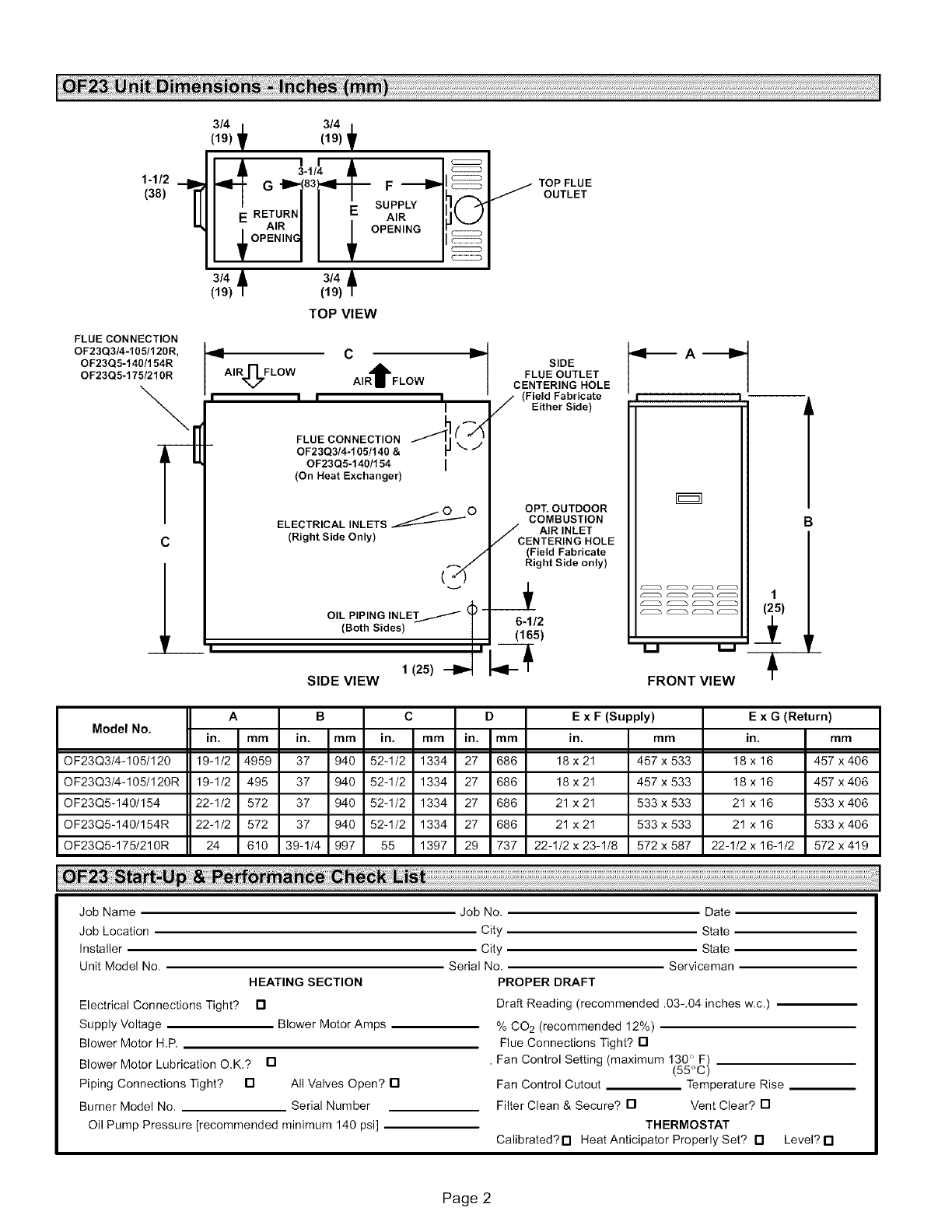
1-1/2
(38)
3/4 3/4 /
(19) f (19) f
3-1/4 &I
G -IP.-(83_'_-_ F _1
3/4 3/4 A
(19) /(19) /
TOP VIEW
FLUE CONNECTION
OF23Q314-1051120R,
OF23Q5-140/154R
OF23Q5-175/210R
c
L
I_ C _
AIR_]TF LOW AIR t FLOW
i i i iI
FLUE CONNECTION ""_I C_
OF23Q3/4-105/140 &
OF23Q5-140/154 I
(On Heat Exchanger)
ELECTRICAL INLETS _O
(Right Side Only)
,4,
OIL PIPING INLET/ _ -
(Both Sides) |
I
1 (25)
SIDE VIEW
TOP FLUE
/OUTLET
SIDE
FLUE OUTLET
CENTERING HOLE
(Field Fabricate
/Either Side)
OPT. OUTDOOR
COMBUSTION
AIR INLET
CENTERING HOLE
(Field Fabricate
Right Side only)
6-1/2
(165)
.... (_)
,, 1
FRONT VIEW
A
Model No. in. mm in.
OF23Q3/4-105/120 19-1/2 4959 37
OF23Q3/4-105/120R 19-1/2 495 37
OF23Q5-140/154 22-1/2 572 37
OF23Q5-140/154R 22-1/2 572 37
OF23Q5-175/210R 24
B C D
mm in. mm in. mm
940 52-1/2 1334 27 686
940 52-1/2 1334 27 686
940 52-1/2 1334 27 686
940 52-1/2 1334 27 686
610 39-1/4 997 55 1397 29 737
E x F (Supply)
in. mm
18 x 21 457 x 533
18 x 21 457 x 533
21 x 21 533 x 533
21 x 21 533 x 533
22-1/2 x 23-1/8 572 x 587
E x G (Return)
in. mm
18 x 16 457 x 406
18 x 16 457 x 406
21 x 16 533 x406
21 x 16 533 x406
22-1/2 x 16-1/2 572 x 419
i!i!i!ialFiii iii3 ii ii ......
Job Name
Job Location
Installer
Unit Model No.
HEATING SECTION
Electrical Connections Tight? 13
Supply Voltage Blower Motor Amps
Blower Motor H.P.
Blower Motor Lubrication O.K.? []
Piping Connections Tight? [] All Valves Open? []
Burner Model No. Serial Number
Oil Pump Pressure [recommended minimum 140 psi]
Job No. Date
City State
City State
Serial No. Serviceman
PROPER DRAFT
Draft Reading (recommended .03-.04 inches w.c.)
% CO 2 (recommended 12%)
Flue Connections Tight? []
• Fan Control Setting (maximum 130 ° F)
(55°C)
Fan Control Cutout Temperature Rise
Filter Clean & Secure? [] Vent Clear? []
THERMOSTAT
Calibrated?[] Heat Anticipator Properly Set? [] Level? []
Page 2
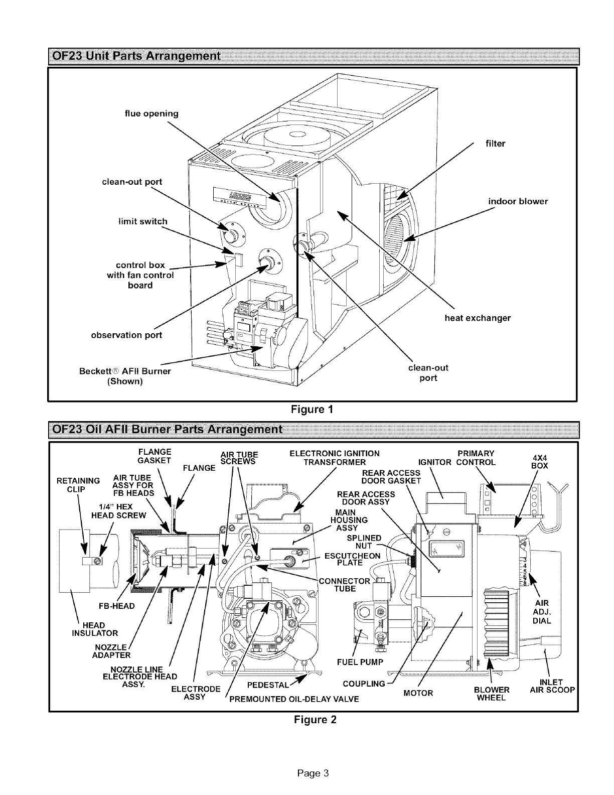
flue opening
filter
clean-out port
limit switch
indoor blower
control box
with fan control
board
observation port
heat exchanger
Beckett_ _,AFII Burner clean-out
(Shown) port
Figure 1
FLANGE AIR TUBE ELECTRONICIGNITION PRIMARY 4X4
GASKET SCREWS TRANSFORMER IGNITOR CONTROL BOX
FLANGE REARACCESS X
DOOR GASKETRETAINING AIR TUBE
ASSY FOR
CLIP FB HEADS
1/4"HEX X
HEAD SCREW
DOORASSY
NUT
INSULATOR
NOZZLE
ADAPTER
NOZZLE LINE
ELECTRODE HEAD /
ASSY. ELECTRODE
ASSY
FUELPUMP
MOTOR BLOWER
WHEEL
Figure 2
VALVE
INLET
AIR SCOOP
Page 3
IWARNING I
Installation of Lennox oil-fired furnaces must conform with
the National Fire Protection Association Standard for the
Installation of Oil Burning Equipment, NFPA No. 31, the
National Electrical Code, ANSI/NFPA No.70 (in the
U.S.A.), CSA Standard CAN/CSA-B139 (in Canada),
Installation Code for Oil Burning Equipment, the Canadian
Electrical Code Part1, CSA 22.1 (Canada), the recommen-
dations of the National Environmental Systems Contrac-
tors Association and any state or provincial laws or local or-
dinances. Authorities having jurisdiction should be
consulted before installation. Such applicable regulations
or requirements take precedence over general instructions
in this manual.
Chimneys and chimney connectors must be of the type and
construction outlined in section 160 of NFPA No. 31.
Air for combustion and ventilation must conform to stan-
dards outlined in section 140 dNFPA No. 31 or, in Canada,
CSA Standard B139. When installing OF23 units in con-
fined spaces such as utility rooms, two combustion air
openings are required. Dimensions of combustion air
openings are shown in table 1. One opening shall be below
burner level and the other opening shall be no more than 6"
(152 mm) from the room's ceiling.
The combustion air opening should provide a minimum free
area one-half square inch per 1,000 Btu per hour input. This
combustion air should be brought into the area containing the
furnace below the level of the furnace burner.
AIMPORTANT
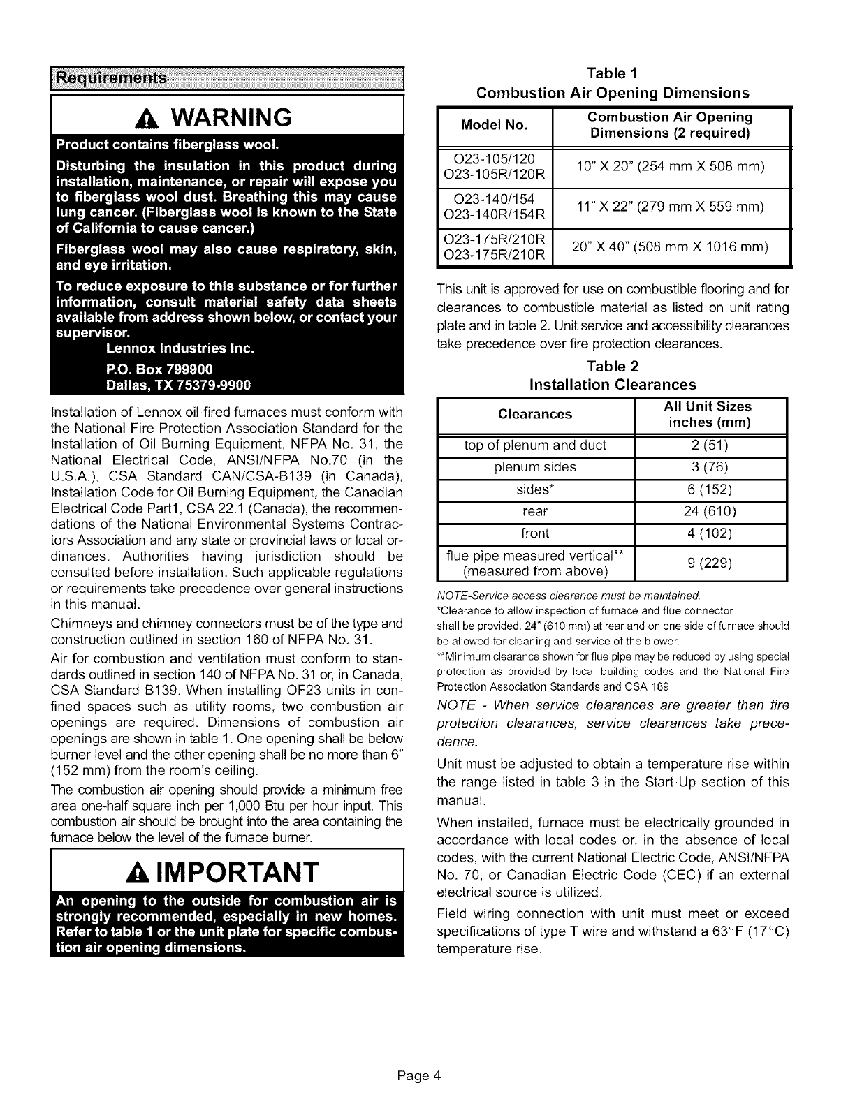
Table 1
Combustion Air Opening Dimensions
Combustion Air Opening
Model No. Dimensions (2 required)
O23-105/120 10" X 20" (254 mm X 508 mm)
O23-105R/120R
O23-140/154 11" X 22" (279 mm X 559 mm)
023-140R/154R
O23-175R/210R 20" X 40" (508 mm X 1016 mm)
O23-175R/210R
This unit is approved for use on combustible flooring and for
clearances to combustible material as listed on unit rating
plate and in table 2, Unit service and accessibility clearances
take precedence over fire protection clearances,
Table 2
Installation Clearances
All Unit Sizes
Clearances inches (mm)
top of plenum and duct 2 (51)
plenum sides 3 (76)
sides* 6 (152)
rear 24 (610)
front 4 (102)
flue pipe measured vertical** 9 (229)
(measured from above)
NOTE-Service access clearance must be maintained.
*Clearance to allow inspection of furnace and flue connector
shall be provided, 24" (610 mm) at rear and on one side of furnace should
be allowed for cleaning and service of the blower.
**Minimum clearance shown for flue pipe may be reduced by using special
protection as provided by local building codes and the National Fire
Protection Association Standards and CSA 189.
NOTE -When service clearances are greater than fire
protection clearances, service clearances take prece-
dence.
Unit must be adjusted to obtain a temperature rise within
the range listed in table 3 in the Start-Up section of this
manual.
When installed, furnace must be electrically grounded in
accordance with local codes or, in the absence of local
codes, with the current National Electric Code, ANSI/NFPA
No. 70, or Canadian Electric Code (CEC) if an external
electrical source is utilized.
Field wiring connection with unit must meet or exceed
specifications of type T wire and withstand a 63<_F(17<_C)
temperature rise.
Page 4
Thecompactdesignof thisfurnacemakesit idealfora
basementor utilityroominstallation.Choosea central
locationfor thefurnacesothatsupplyairductsapproxi-
matelythesamelength.Thiswillalloweachroomto re-
ceivetheproperamountof heat.Thefurnaceshouldbe
placedsothattheflueconnectiontothechimneywillbeof
minimumlengthandhaveaminimumnumberofelbows.
1- Setthe unitin desiredlocationkeepingin mindthe
clearanceslistedintable2.Alsokeepinmindoilsup-
ply connections,electricalsupply,flueconnections
andsufficientclearancefor installingandservicing
unit.
2- Leveltheunitfromsidetosideandfromfronttorear.If
thefurnaceis not level,placefireproofwedgesor
shimsbetweenthe lowsideof thefurnaceandthe
floor.Makesuretheweightofthefurnaceisdistributed
evenlyonallfourcorners.Strainonsidesof cabinet
causingcrackingand poppingnoisesmayoccurif
weightoffurnaceisnotevenlydistributed.
Neitherthenozzlesettingnortheairadjustmentsarefacto-
ry set.Thefurnaceisfiretestedandthelimitcontrolis
checkedtomakesureitfunctionsproperly;nofactoryset-
tingsaremade.Duringinstallation,thefurnacemustbe
"setup,"Theinstallingdealer/contractormusthaveand
usepropertestequipmentinordertocorrectlysetuptheoil
furnace,Propertestingequipmentis requiredto ensure
correctoperationoftheunit.Theuseoftestequipmentis
nowmorecriticalthaneverduetotightertolerancesneed-
edto keepthefurnaceoperatingefficiently.
Amongthetestequipmentfor anoilfurnace,theproper
combustiontestkitshouldcontainthefollowing:
• Draftgauge
• CO2or02Analyzer
• Smoketester
• Pressuregauge
• Hightemperaturethermometer
• Oilvacuumgauge
• BeckettT-500gauge
• Knowledgeofpropertestequipmentoperation
CAUTION
Nozzle Adjustment
Proper adjustment of the nozzle assembly is critical because
alignment may have changed during shipping. Before the fur-
nace and oil lines are installed, the nozzle assembly must be
checked. This may easily be done by removing the entire
burner assembly (not just the nozzle) from the furnace. The
lower firing nozzle is factory installed. This should be verified
by the installer. Inspect the spark transformer leads also to
ensure they are still attached to the electrodes. Note that
OF23-105/120 and OF23-140/154 series units use the
Beckett AFII burner. OF23-175/210R series units use the
Beckett AFG burner.
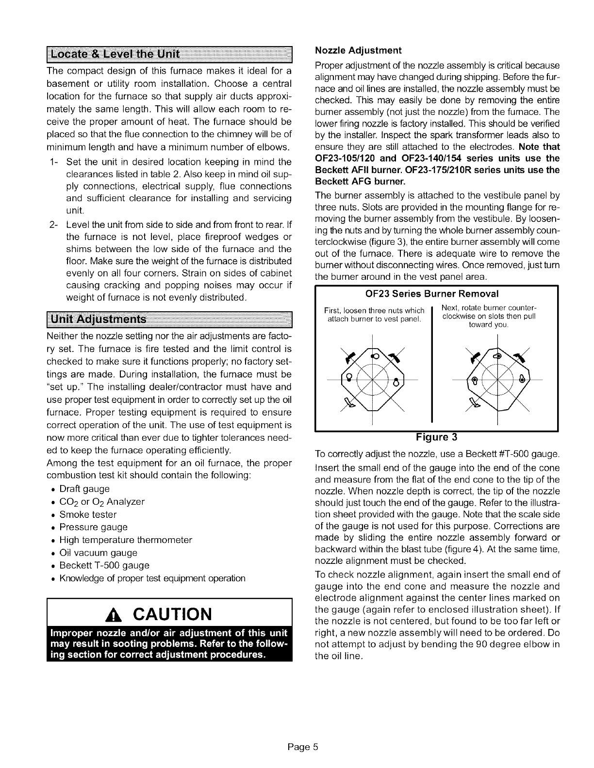
The burner assembly is attached to the vestibule panel by
three nuts. Slots are provided in the mounting flange for re-
moving the burner assembly from the vestibule. By loosen-
ing the nuts and by turning the whole burner assembly coun-
terclockwise (figure 3), the entire burner assembly will come
out of the furnace. There is adequate wire to remove the
burner without disconnecting wires. Once removed, just turn
the burner around in the vest panel area.
OF23 Series Burner Removal
First, loosen three nuts which
attach burner to vest panel.
Next, rotate burner counter-
clockwise on slots then pull
toward rou.
Figure 3
To correctly adjust the nozzle, use a Beckett #T-500 gauge.
Insert the small end of the gauge into the end of the cone
and measure from the flat of the end cone to the tip of the
nozzle. When nozzle depth is correct, the tip of the nozzle
should just touch the end of the gauge. Refer to the illustra-
tion sheet provided with the gauge. Note that the scale side
of the gauge is not used for this purpose. Corrections are
made by sliding the entire nozzle assembly forward or
backward within the blast tube (figure 4). At the same time,
nozzle alignment must be checked.
To check nozzle alignment, again insert the small end of
gauge into the end cone and measure the nozzle and
electrode alignment against the center lines marked on
the gauge (again refer to enclosed illustration sheet). If
the nozzle is not centered, but found to be too far left or
right, a new nozzle assembly will need to be ordered. Do
not attempt to adjust by bending the 90 degree elbow in
the oil line.
Page 5
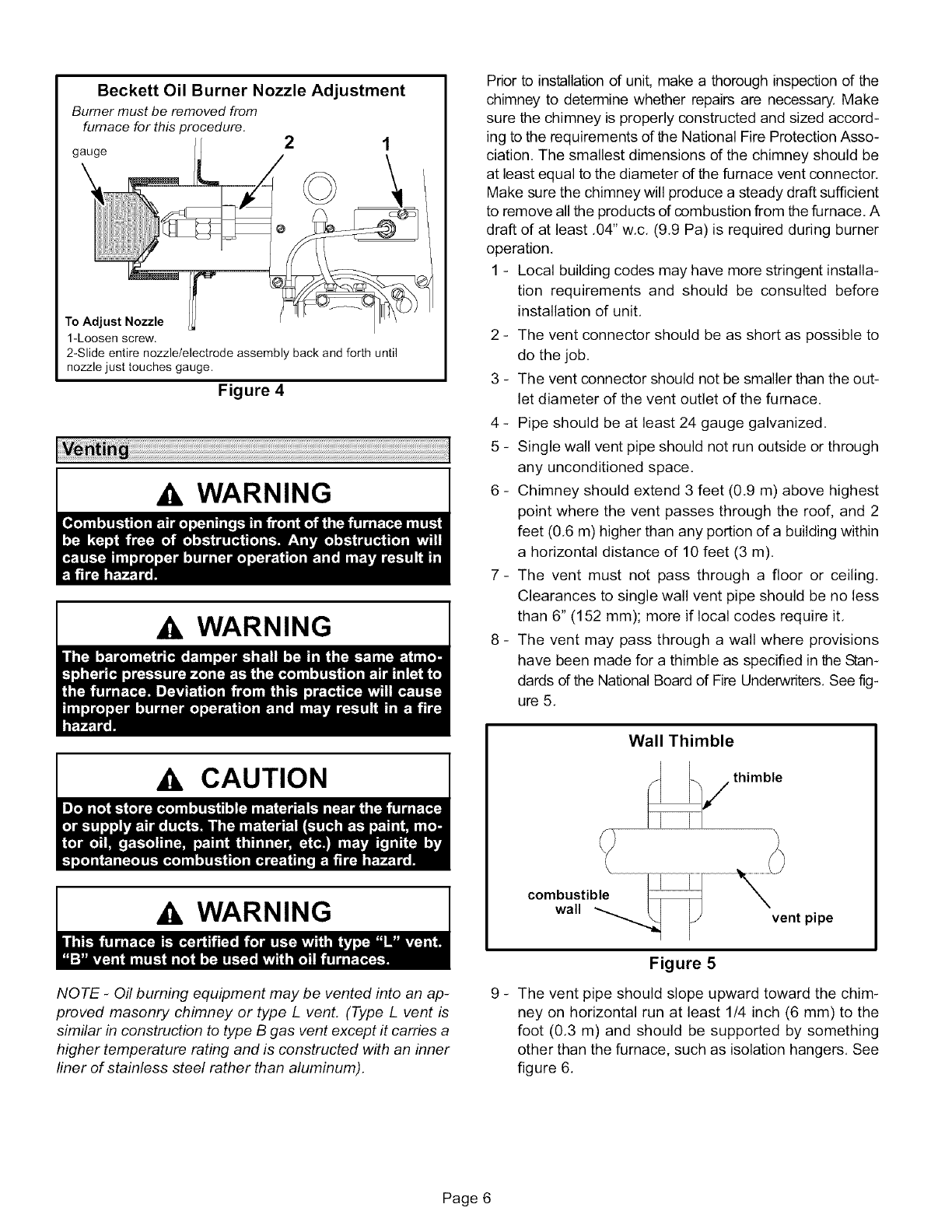
Beckett Oil Burner Nozzle Adjustment
Burner must be removed from
furnace for thisprocedure. 2 1
gauge
To Adjust Nozzle
1-Loosen screw.
2-Slide entire nozzle/electrode assembly back and forth until
nozzle just touches gauge.
Figure 4
WARNING
WARNING
CAUTION
WARNING
I
NOTE -Oil burning equipment may be vented into an ap-
proved masonry chimney or type L vent. (Type L vent is
similar in construction to type B gas vent except it carries a
higher temperature rating and is constructed with an inner
liner of stainless steel rather than aluminum).
Prior to installation of unit, make a thorough inspection of the
chimney to determine whether repairs are necessary. Make
sure the chimney is properly constructed and sized accord-
ing to the requirements of the National Fire Protection Asso-
ciation. The smallest dimensions dthe chimney should be
at least equal to the diameter dthe furnace vent connector.
Make sure the chimney will produce a steady draft sufficient
to remove all the products of combustion from the furnace. A
draft of at least ,04" w,c, (9,9 Pa) is required during burner
operation,
1 - Local building codes may have more stringent installa-
tion requirements and should be consulted before
installation of unit,
2 - The vent connector should be as short as possible to
do the job,
3 - The vent connector should not be smaller than the out-
let diameter of the vent outlet of the furnace.
4 - Pipe should be at least 24 gauge galvanized,
5 - Single wall vent pipe should not run outside or through
any unconditioned space,
6 - Chimney should extend 3 feet (0.9 m) above highest
point where the vent passes through the roof, and 2
feet (0,6 m) higher than any portion of a building within
a horizontal distance of 10 feet (3 m),
7- The vent must not pass through a floor or ceiling,
Clearances to single wall vent pipe should be no less
than 6" (152 mm); more if local codes require it,
8 - The vent may pass through a wall where provisions
have been made for a thimble as specified in the Stan-
dards of the National Board of Fire Underwriters, See fig-
ure 5,
Wall Thimble
combustible
wall vent pipe
Figure 5
9 - The vent pipe should slope upward toward the chim-
ney on horizontal run at least 1/4 inch (6 mm) to the
foot (0.3 m) and should be supported by something
other than the furnace, such as isolation hangers. See
figure 6.
Page 6
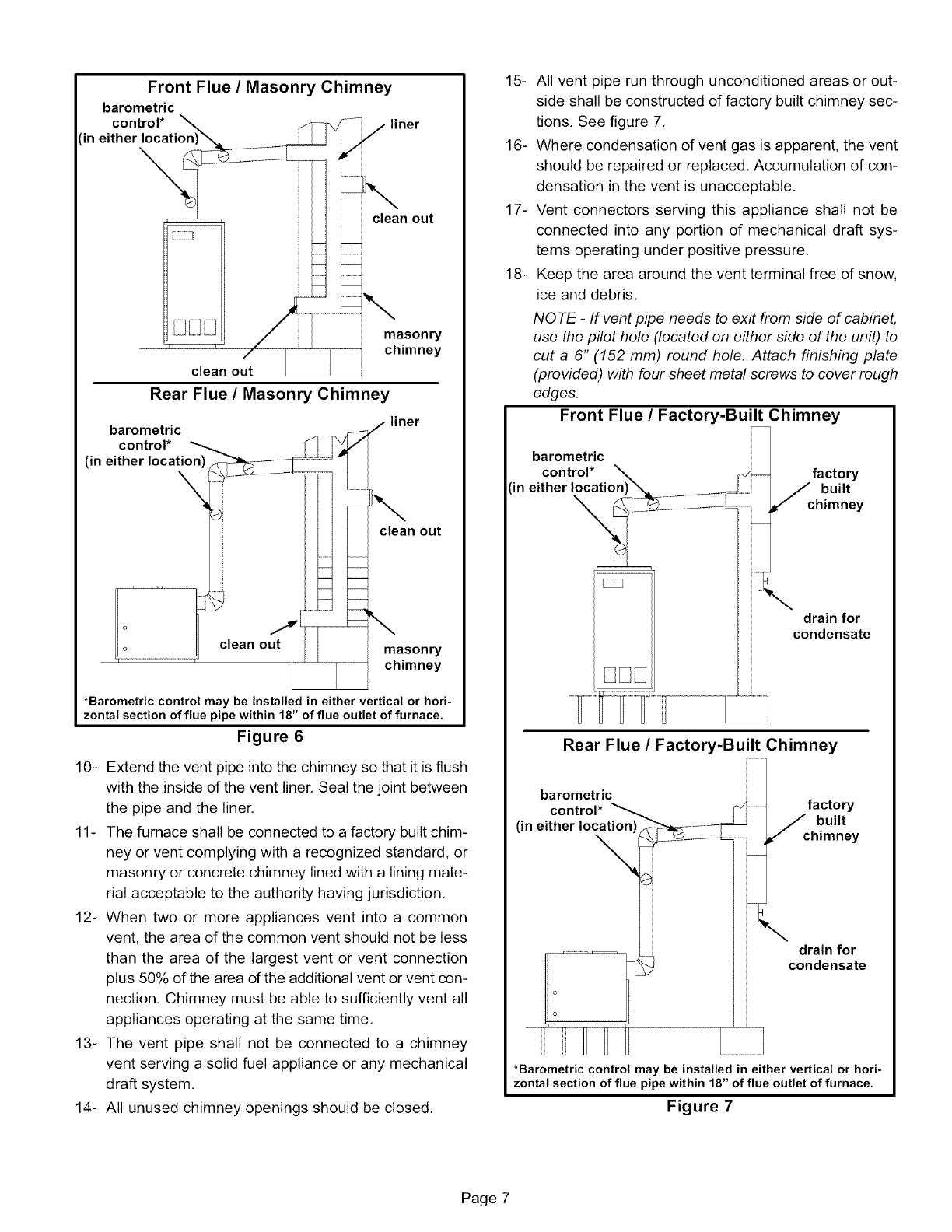
Front Flue /Masonry Chimney
barometric
control* liner
in either location
\
clean out
masonry
chimney
clean out
Rear Flue /Masonry Chimney
barometric
control* _ _'
(in either location) - -_S .......... I -- '
lean o _m,m, asonry
ichimney
*Barometric control may be installed in either vertical or hori-
zontal section of flue pipe within 18" of flue outlet of furnace.
Figure 6
10- Extend the vent pipe into the chimney so that it is flush
with the inside of the vent liner. Seal the joint between
the pipe and the liner.
11- The furnace shall be connected to a factory built chim-
ney or vent complying with a recognized standard, or
masonry or concrete chimney lined with a lining mate-
rial acceptable to the authority having jurisdiction,
12- When two or more appliances vent into a common
vent, the area of the common vent should not be less
than the area of the largest vent or vent connection
plus 50% of the area of the additional vent or vent con-
nection. Chimney must be able to sufficiently vent all
appliances operating at the same time,
13- The vent pipe shall not be connected to a chimney
vent serving a solid fuel appliance or any mechanical
draft system,
14- All unused chimney openings should be closed,
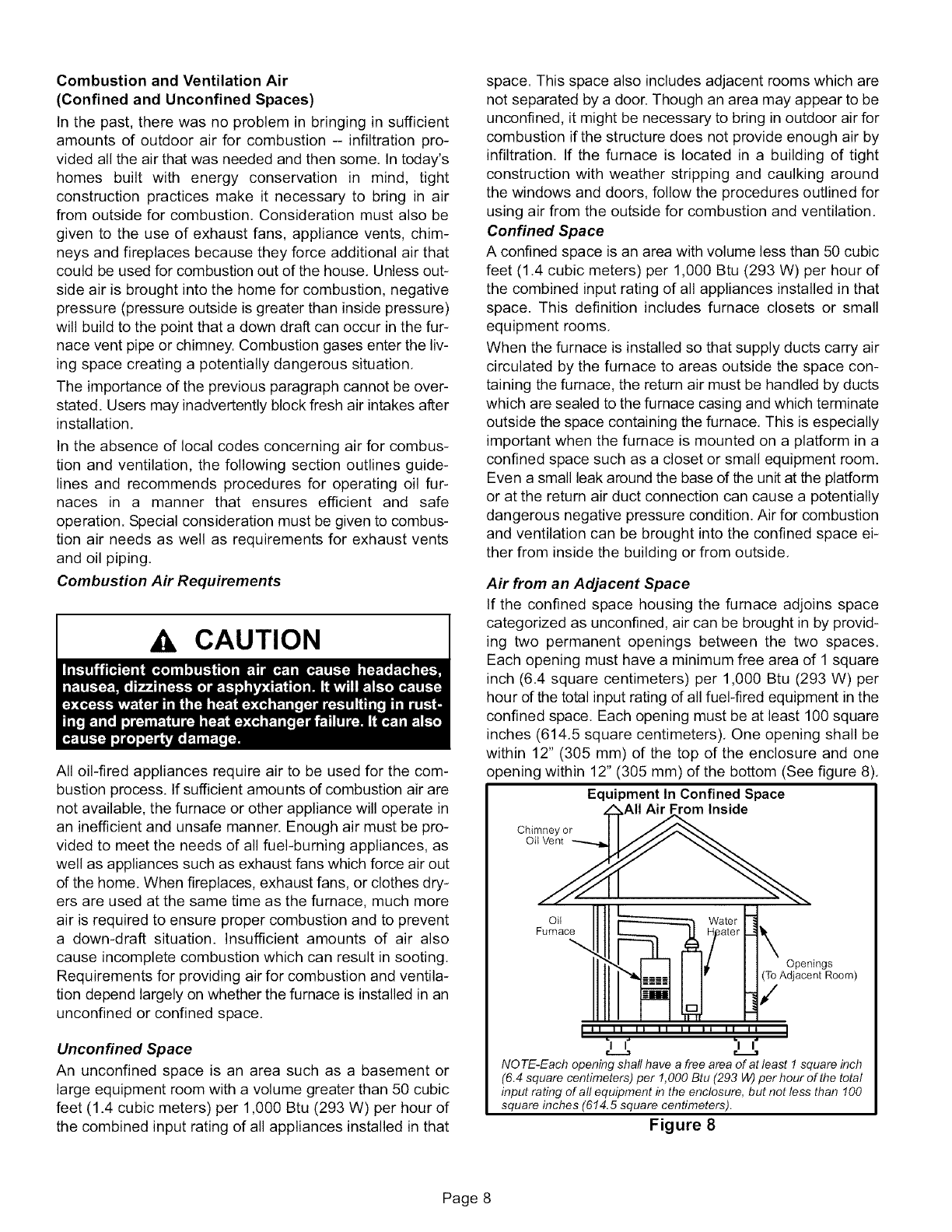
15- All vent pipe run through unconditioned areas or out-
side shall be constructed of factory built chimney sec-
tions. See figure 7,
16- Where condensation of vent gas is apparent, the vent
should be repaired or replaced, Accumulation of con-
densation in the vent is unacceptable.
17- Vent connectors serving this appliance shall not be
connected into any portion of mechanical draft sys-
tems operating under positive pressure,
18- Keep the area around the vent terminal free of snow,
ice and debris,
NOTE -If vent pipe needs to exit from side of cabinet,
use the pilot hole (located on either side of the unit) to
cut a 6" (152 mm) round hole. Attach finishing plate
(provided) with four sheet metal screws to cover rough
edges.
Front Flue /Factory-Built Chimney
barometric
control*
in either location
\factory
_built
chimney
drain for
condensate
Rear Flue /Factory-Built Chimney
barometric
control*
(in either location
i o
i o
factory
Jc built
himney
drain for
condensate
I
*Barometric control may be installed in either vertical or hori-
zontal section of flue pipe within 18" of flue outlet of furnace.
Figure 7
Page 7
Combustion and Ventilation Air
(Confined and Unconfined Spaces)
In the past, there was no problem in bringing in sufficient
amounts of outdoor air for combustion - infiltration pro-
vided all the air that was needed and then some. In today's
homes built with energy conservation in mind, tight
construction practices make it necessary to bring in air
from outside for combustion, Consideration must also be
given to the use of exhaust fans, appliance vents, chim-
neys and fireplaces because they force additional air that
could be used for combustion out of the house, Unless out-
side air is brought into the home for combustion, negative
pressure (pressure outside is greater than inside pressure)
will build to the point that a down draft can occur in the fur-
nace vent pipe or chimney. Combustion gases enter the liv-
ing space creating a potentially dangerous situation,
The importance of the previous paragraph cannot be over-
stated. Users may inadvertently block fresh air intakes after
installation,
In the absence of local codes concerning air for combus-
tion and ventilation, the following section outlines guide-
lines and recommends procedures for operating oil fur-
naces in a manner that ensures efficient and safe
operation. Special consideration must be given to combus-
tion air needs as well as requirements for exhaust vents
and oil piping,
Combustion Air Requirements
Ak CAUTION
All oil-fired appliances require air to be used for the com-
bustion process. If sufficient amounts of combustion air are
not available, the furnace or other appliance will operate in
an inefficient and unsafe manner. Enough air must be pro-
vided to meet the needs of all fuel-burning appliances, as
well as appliances such as exhaust fans which force air out
of the home. When fireplaces, exhaust fans, or clothes dry-
ers are used at the same time as the furnace, much more
air is required to ensure proper combustion and to prevent
a down-draft situation. Insufficient amounts of air also
cause incomplete combustion which can result in sooting.
Requirements for providing air for combustion and ventila-
tion depend largely on whether the furnace is installed in an
unconfined or confined space.
Unconfined Space
An unconfined space is an area such as a basement or
large equipment room with a volume greater than 50 cubic
feet (1.4 cubic meters) per 1,000 Btu (293 W) per hour of
the combined input rating of all appliances installed in that
space. This space also includes adjacent rooms which are
not separated by a door. Though an area may appear to be
unconfined, it might be necessary to bring in outdoor air for
combustion if the structure does not provide enough air by
infiltration, If the furnace is located in a building of tight
construction with weather stripping and caulking around
the windows and doors, follow the procedures outlined for
using air from the outside for combustion and ventilation,
Confined Space
A confined space is an area with volume less than 50 cubic
feet (1,4 cubic meters) per 1,000 Btu (293 W) per hour of
the combined input rating of all appliances installed in that
space. This definition includes furnace closets or small
equipment rooms,
When the furnace is installed so that supply ducts carry air
circulated by the furnace to areas outside the space con-
taining the furnace, the return air must be handled by ducts
which are sealed to the furnace casing and which terminate
outside the space containing the furnace, This is especially
important when the furnace is mounted on a platform in a
confined space such as a closet or small equipment room.
Even a small leak around the base of the unit at the platform
or at the return air duct connection can cause a potentially
dangerous negative pressure condition. Air for combustion
and ventilation can be brought into the confined space ei-
ther from inside the building or from outside,
Air from an Adjacent Space
If the confined space housing the furnace adjoins space
categorized as unconfined, air can be brought in by provid-
ing two permanent openings between the two spaces.
Each opening must have a minimum free area of 1 square
inch (6,4 square centimeters) per 1,000 Btu (293 W) per
hour of the total input rating of all fuel-fired equipment in the
confined space. Each opening must be at least 100 square
inches (614,5 square centimeters), One opening shall be
within 12" (305 mm) of the top of the enclosure and one
opening within 12" (305 mm) of the bottom (See figure 8),
Equipment In Confined Space
rom Inside
Chimney or
Oil Vent
Oil
Furnace
Openings
(To Adjacent Room)
i ii ii ii ii ii ii ii ii i
'"1 I" "I I°'
NO TE-Each opening shall have a free area of at least I square inch
(6.4 square centimeters) per 1,000 Btu (293 W) per hour of the total
input rating of all equipment in the enclosure, but not less than 100
square inches (614.5 square centimeters).
Figure 8
Page 8
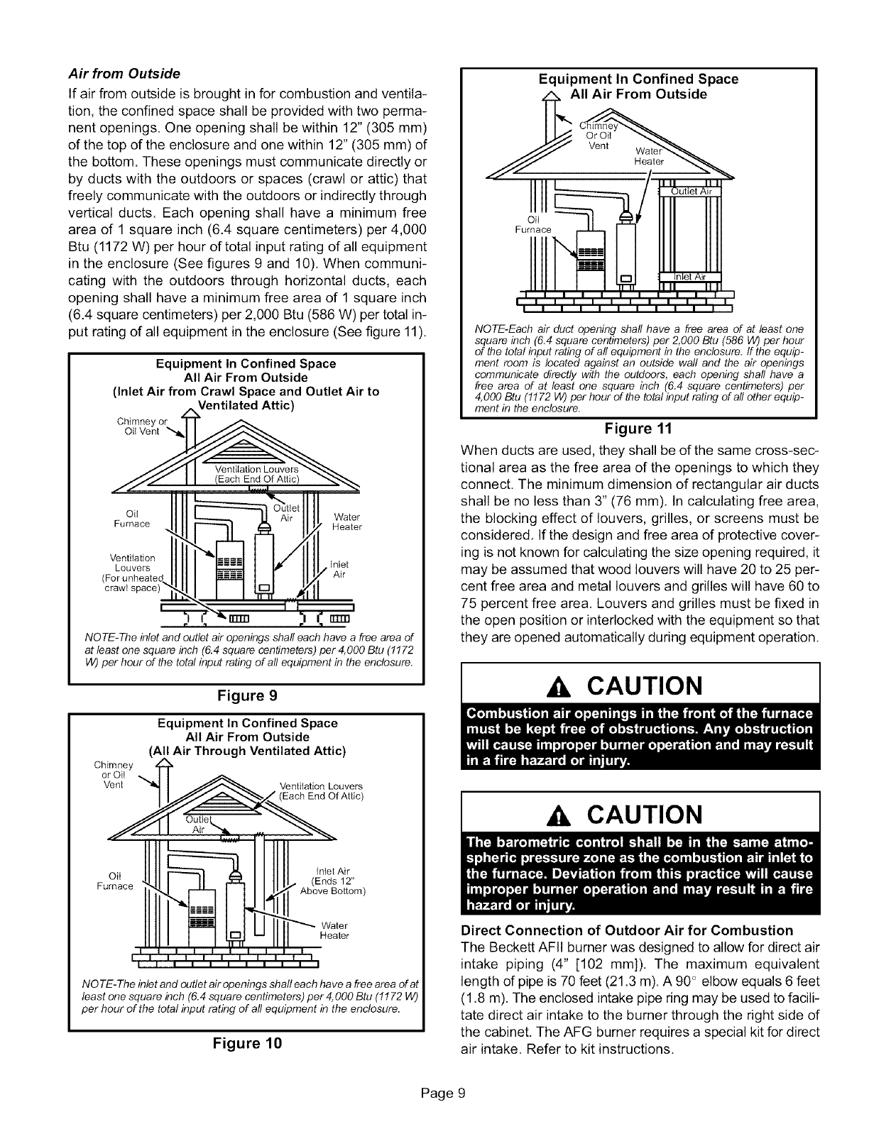
Air from Outside
If air from outside is brought in for combustion and ventila-
tion, the confined space shall be provided with two perma-
nent openings. One opening shall be within 12" (305 mm)
of the top of the enclosure and one within 12" (305 mm) of
the bottom. These openings must communicate directly or
by ducts with the outdoors or spaces (crawl or attic) that
freely communicate with the outdoors or indirectly through
vertical ducts. Each opening shall have a minimum free
area of 1 square inch (6.4 square centimeters) per 4,000
Btu (1172 W) per hour of total input rating of all equipment
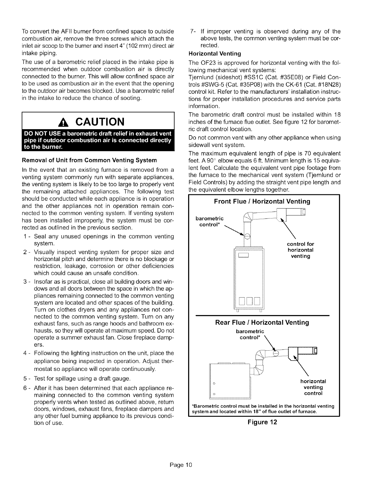
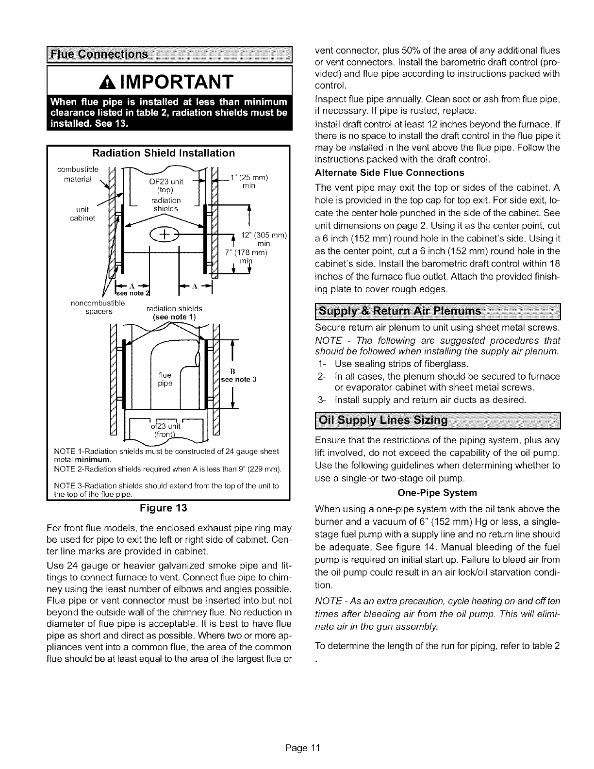
in the enclosure (See figures 9 and 10). When communi-
cating with the outdoors through horizontal ducts, each
opening shall have a minimum free area of 1 square inch
(6.4 square centimeters) per 2,000 Btu (586 W) per total in-
put rating of all equipment in the enclosure (See figure 11).
Equipment In Confined Space
All Air From Outside
(Inlet Air from Crawl Space and Outlet Air to
Ventilated Attic)
Chimney or
Oil Vent '_
Oil Water
Furnace Heater
Ventilation
Louvers Inlet
(For unheate( Air
crawt
rrrm
r1r
NOTE-The inlet and outlet air openings shall each have a free area of
at least one square inch (6.4 square centimeters) per 4,000 Btu (!! 72
W) per hour of the total input rating of all equipment in the enclosure.
Chimney
or Oil
Vent
Figure 9
Equipment In Confined Space
All Air From Outside
(All Air Through Ventilated Attic)
Ventilation Louvers
• (Each End Of Attic)
Oil Inlet Air
(Ends 12"
Furnace Above BoSom)
Water
Heater
NO TE-The inlet and outlet air openings shall each have a free area of at
least one square inch (6.4 square centimeters) per 4,000 Btu (1172 W)
per hour of the total input rating of all equipment in the enclosure.
Figure 10
Equipment In Confined Space
AII Air From Outside
Or Oil
Vent Heater
1 1 I I I I I 1 1 I I I
I 1 1 I I I I 1 1 1 I I
NOTE-Each air duct opening shall have a free area d at least one
square inch (6.4 square centimeters) per 2,000 Btu (586 W) per hour
of the total input rating of all equipment in the enclosure, ff the equip-
ment room is located against an outside wall and the air openings
communicate directly with the outdoors, each opening shall have a
free area d at least one square inch (6.4 square centimeters) per
4,000 Btu (!! 72 W) per hour of the total input rating of all other equip-
ment in the enclosure.
Figure 11
When ducts are used, they shall be of the same cross-sec-
tional area as the free area of the openings to which they
connect. The minimum dimension of rectangular air ducts
shall be no less than 3" (76 mm). In calculating free area,
the blocking effect of louvers, grilles, or screens must be
considered. If the design and free area of protective cover-
ing is not known for calculating the size opening required, it
may be assumed that wood louvers will have 20 to 25 per-
cent free area and metal louvers and grilles will have 60 to
75 percent free area. Louvers and grilles must be fixed in
the open position or interlocked with the equipment so that
they are opened automatically during equipment operation.
CAUTION
A CAUTION
Direct Connection of Outdoor Air for Combustion
The Beckett AFII burner was designed to allow for direct air
intake piping (4" [102 mm]). The maximum equivalent
length of pipe is 70 feet (21.3 m). A 90 _elbow equals 6 feet
(1.8 m). The enclosed intake pipe ring may be used to facili-
tate direct air intake to the burner through the right side of
the cabinet. The AFG burner requires a special kit for direct
air intake. Refer to kit instructions.
Page 9
ToconverttheAFItburnerfromconfinedspacetooutside
combustionair,removethethreescrewswhichattachthe
inletairscooptotheburnerandinsert4"(102mm)directair
intakepiping.
Theuseofa barometricreliefplacedintheintakepipeis
recommendedwhenoutdoorcombustionair is directly
connectedtotheburner.Thiswillallowconfinedspaceair
tobeusedascombustionairintheeventthattheopening
totheoutdoorairbecomesblocked.Useabarometricrelief
intheintaketoreducethechanceofsooting.
CAUTION
Removal of Unit from Common Venting System
In the event that an existing furnace is removed from a
venting system commonly run with separate appliances,
the venting system is likely to be too large to properly vent
the remaining attached appliances. The following test
should be conducted while each appliance is in operation
and the other appliances not in operation remain con-
nected to the common venting system. If venting system
has been installed improperly, the system must be cor-
rected as outlined in the previous section.
1-Seal any unused openings in the common venting
system.
2 - Visually inspect venting system for proper size and
horizontal pitch and determine there is no blockage or
restriction, leakage, corrosion or other deficiencies
which could cause an unsafe condition.
3 - Insofar as is practical, close all building doors and win-
dows and all doors between the space in which the ap-
pliances remaining connected to the common venting
system are located and other spaces of the building.
Turn on clothes dryers and any appliances not con-
nected to the common venting system. Turn on any
exhaust fans, such as range hoods and bathroom ex-
hausts, so they will operate at maximum speed. Do not
operate a summer exhaust fan. Close fireplace damp-
ers.
4 - Following the lighting instruction on the unit, place the
appliance being inspected in operation. Adjust ther-
mostat so appliance will operate continuously.
5 - Test for spillage using a draft gauge.
6 - After it has been determined that each appliance re-
maining connected to the common venting system
properly vents when tested as outlined above, return
doors, windows, exhaust fans, fireplace dampers and
any other fuel burning appliance to its previous condi-
tion of use.
7- If improper venting is observed during any of the
above tests, the common venting system must be cor-
rected.
Horizontal Venting
The OF23 is approved for horizontal venting with the fol-
lowing mechanical vent systems:
Tjernlund (sideshot) #SSlC (Cat. #35E08) or Field Con-
trols #SWG-5 (Cat. #35P08) with the CK-61 (Cat. #18N28)
control kit. Refer to the manufacturers' installation instruc-
tions for proper installation procedures and service parts
information.
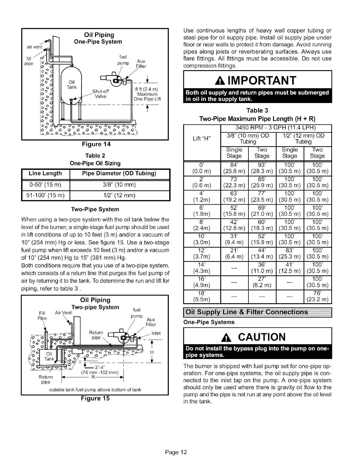
The barometric draft control must be installed within 18
inches of the furnace flue outlet. See figure 12 for baromet-
ric draft control location.
Do not common vent with any other appliance when using
sidewall vent system.
The maximum equivalent length of pipe is 70 equivalent
feet. A 90_ elbow equals 6 ft. Minimum length is 15 equiva-
lent feet. Calculate the equivalent vent pipe footage from
the furnace to the mechanical vent system (Tjernlund or
Field Controls) by adding the straight vent pipe length and
the equivalent elbow lengths together.
Front Flue /Horizontal Venting
bar°_;tlr) c "__::-- control for
[ZZ horizontal
venting
Rear Flue /Horizontal Venting
barometric
control*
*Barometric control must be installed in the horizontal venting
system and located within 18" of flue outlet of furnace.
Figure 12
Page 10
IMPORTANT
Radiation Shield Installation
combustible
material
unit
cabinet
(25 mm)
min
12" (305 mm)
min
7" (178 mm)
noncombustible
spacers radiation shields
(see note 1)
B
see note 3
NOTE 1-Radiation shields must be constructed of 24 gauge sheet
metal minimum.
NOTE 2-Radiation shields required when A is less than 9" (229 ram),
NOTE 3-Radiation shields should extend from the top of the unit to
the top of the flue pipe.
Figure 13
For front flue models, the enclosed exhaust pipe ring may
be used for pipe to exit the left or right side of cabinet. Cen-
ter line marks are provided in cabinet.
Use 24 gauge or heavier galvanized smoke pipe and fit-
tings to connect furnace to vent. Connect flue pipe to chim-
ney using the least number of elbows and angles possible.
Flue pipe or vent connector must be inserted into but not
beyond the outside wall of the chimney flue. No reduction in
diameter of flue pipe is acceptable. It is best to have flue
pipe as short and direct as possible. Where two or more ap-
pliances vent into a common flue, the area of the common
flue should be at least equal to the area of the largest flue or
vent connector, plus 50% of the area of any additional flues
or vent connectors. Install the barometric draft control (pro-
vided) and flue pipe according to instructions packed with
control.
Inspect flue pipe annually. Clean soot or ash from flue pipe,
if necessary. If pipe is rusted, replace.
Install draft control at least 12 inches beyond the furnace. If
there is no space to install the draft control in the flue pipe it
may be installed in the vent above the flue pipe. Follow the
instructions packed with the draft control.
Alternate Side Flue Connections
The vent pipe may exit the top or sides of the cabinet. A
hole is provided in the top cap for top exit. For side exit, lo-
cate the center hole punched in the side of the cabinet. See
unit dimensions on page 2. Using it as the center point, cut
a 6 inch (152 mm) round hole in the cabinet's side. Using it
as the center point, cut a 6 inch (152 mm) round hole in the
cabinet's side. Install the barometric draft control within 18
inches dthe furnace flue outlet. Attach the provided finish-
ing plate to cover rough edges.
Secure return air plenum to unit using sheet metal screws.
NOTE -The following are suggested procedures that
should be followed when installing the supply air plenum.
1- Use sealing strips of fiberglass.
2- In all cases, the plenum should be secured to furnace
or evaporator cabinet with sheet metal screws.
3- Install supply and return air ducts as desired.
Ensure that the restrictions of the piping system, plus any
lift involved, do not exceed the capability of the oil pump.
Use the following guidelines when determining whether to
use a single-or two-stage oil pump.
One-Pipe System
When using a one-pipe system with the oil tank above the
burner and a vacuum of 6" (152 mm) Hg or less, a single-
stage fuel pump with a supply line and no return line should
be adequate. See figure 14. Manual bleeding of the fuel
pump is required on initial start up. Failure to bleed air from
the oil pump could result in an air lock/oil starvation condi-
tion.
NOTE -As an extra precaution, cycle heating on and off ten
times after bleeding air from the oil pump. This will elimi-
nate air in the gun assembly.
To determine the length of the run for piping, refer to table 2
Page 11
r_ Oil Piping
IIOne-Pipe System
alrv LII
fill / dl I_ fuel
,oum Aux
pipe o_L P: P Filter
t-)_r
O O _'-'
IIT;,kI ..... 18ft<24m)
o ° ol II / _nut-o_ _ ,'
o_-I I1 _ Valve ] Maximum
o;;I It_ ,_ I One Pipe Lift
o_ .........
ITlllT--- t
o_
xql !') Uu
x_,o ;,o;,o;,o;,o;,o;,o;,o;,
Figure 14
Table 2
One-Pipe Oil Sizing
Line Length Pipe Diameter (OD Tubing)
0-50' (15 m) 3/8" (10 mm)
51-100' (15 m) 1/2" (12 mm)
Two-Pipe System
When using a two-pipe system with the oil tank below the
level of the burner, a single-stage fuel pump should be used
in lift conditions of up to 10 feet (3 m) and/or a vacuum of
10" (254 mm) Hg or less. See figure 15. Use a two-stage
fuel pump when lift exceeds 10 feet (3 m) and/or a vacuum
of 10" (254 mm) Hg to 15" (381 mm) Hg,
Both conditions require that you use of a two-pipe system,
which consists of a return line that purges the fuel pump of
air by returning it to the tank. To determine the run and lift for
piping, refer to table 3.
Oil Piping
Two-pipe System fuel
Fill Air Vent
Pipe _, r] pump Aux
\ "_11 _ Filter
I eturn
/_IF_J I p,pe_,,__ _
•:,)-_ /
__ J_-v_7_L_._- - _
_ _-1o2 mintJ
outside tank fuel pump above bottom of tank
Figure 15
Use continuous lengths of heavy wall copper tubing or
steel pipe for oil supply pipe, Install oil supply pipe under
floor or near walls to protect it from damage, Avoid running
pipes along joists or reverberating surfaces. Always use
flare fittings. All fittings must be accessible. Do not use
compression fittings.
_k IMPORTANT
Two-Pi
Table 3
)e Maximum Pipe Length (H + R)
3450 RPM- 3 GPH (11.4 LPH)
3/8" (10 mm) OD 1/2" (12 mm) OD
Lift "H" Tubing Tubing
Single Two Single Two
Stage Stage Stage Stage
84' 93' 100' 100'
(25.6 m) (28.3 m) (30.5 m) (30.5 m)
73' 85' 100' 100'
(22.3 m) (25.9 m) (30.5 m) (30.5 m)
63' 77' 100' 100'
(19.2 m) (23.5 m) (30.5 m) (30.5 m)
52' 69' 100' 100'
(15.8 m) (21.0 m) (30.5 m) (30.5 m)
42' 60' 100' 100'
(12.8 m) (18.3 m) (30.5 m) (30.5 m)
31' 52' 100' 100'
(9.4 m) (15.9 m) (30.5 m) (30.5 m)
21' 44' 83' 100'
(6.4 m) (13.4 m) (25.3 m) (30.5 m)
36' 41' 100'
(11.0 m) (12.5 m) (30.5 m)
27' 100'
(8.2 m) (30.5 m)
76'
0)
(0.0 m)
2'
(0.6 m)
4'
(1.2m)
6'
(1.8m)
8'
(2.4m)
10'
(3.0m)
12'
(3.7m)
14'
(4.3m)
16'
(4.9m)
18'
(5.5m) (23.2 m)
F
One-Pipe Systems
A CAUTION
The burner is shipped with fuel pump set for one-pipe op-
eration. For one-pipe systems, the oil supply pipe is con-
nected to the inlet tap on the pump, A one-pipe system
should only be used where there is gravity oil flow to the
pump and the pipe is not run at any point above the oil level
in the tank.
Page 12
1- Connecttheinletpipetothepumpinlet,Starttheburner.
2 - Arrangetheprimaryburnercontrolforcontinuousop-
erationduringpurging,Seefigure14,
3- Turnthebleedvalveoneturncounterclockwise,
4 - Bleedtheunituntilallairbubblesdisappear.
NOTE -Hurried bleeding will prevent the unit from op-
erating properly.
5 - Tighten the bleed valve securely,
Two-Pipe Systems
If the installation requires a two-pipe operation, install the
bypass plug included in the bag which is attached to the
pump, To convert the pump, install the bypass plug accord-
ing to the provided pump instructions, Notice in the two-pipe
system the return pipe must terminate in the tank 3" (76 mm)
to 4" (102 mm) above the supply inlet. Ensure the return pipe
terminates at the correct measurement or air may escape
into the system, This could result in loss of prime,
NOTE- If using an outside tank in cold climates a number
one fuel or an oil treatment is strongly recommended.
1 - Remove 1/4" plug from return port,
2 - Insert bypass plug and tighten it, See figure 15.
3 - Attach the return and inlet pipes, Start the burner. Air
bleeding is automatic,
NOTE -If a faster bleed is necessarj4 open the bleed
valve,
4 - The return pipe must terminate 3" to 4" above the sup-
ply pipe inlet, See figure 15,
NOTE -If the return pipe does not terminate where it
should, air may enter the system, and prime may be
lost.
An oil filter is required for all models. Install filter inside
the building between the tank shut-off valve and the burner.
Locate filter close to burner for easy maintenance, Table 4
lists the filters for the OF23 furnace,
Consult the burner manufacturer's instructions that are in-
cluded with the unit for further details concerning oil supply
pipe connections.
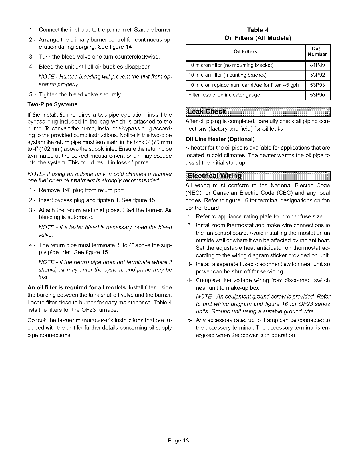
Table 4
Oil Filters (All Models)
Cat.
Oil Filters Number
10 micron filter (no mounting bracket) 81P89
10 micron filter (mounting bracket) 53P92
10 micron replacement cartridge for filter, 45 gph 53P93
Filter restriction indicator gauge 53P90
After oil piping is completed, carefully check all piping con-
nections (factory and field) for oil leaks,
Oil Line Heater (Optional)
A heater for the oil pipe is available for applications that are
located in cold climates, The heater warms the oil pipe to
assist the initial start-up.
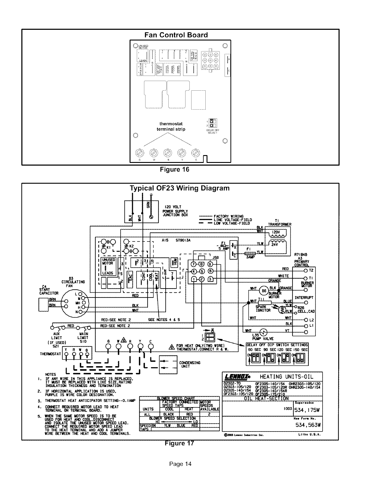
All wiring must conform to the National Electric Code
(NEC), or Canadian Electric Code (CEC) and any local
codes, Refer to figure 16 for terminal designations on fan
control board,
1- Refer to appliance rating plate for proper fuse size,
2- Install room thermostat and make wire connections to
the fan control board, Avoid installing thermostat on an
outside wall or where it can be affected by radiant heat,
Set the adjustable heat anticipator on thermostat ac-
cording to the wiring diagram sticker provided on unit,
3- Install a separate fused disconnect switch near unit so
power can be shut off for servicing.
4- Complete line voltage wiring from disconnect switch
near unit to make-up box.
NOTE -An equipment ground screw is provided. Refer
to unit wiring diagram and figure 16 for 0F23 series
units. Ground unit using a suitable ground wire.
5- Any accessory rated up to 1 amp can be connected to
the accessory terminal. The accessory terminal is en-
ergized when the blower is in operation.
Page 13
Fan Control Board
©
thermostat _[]
terminal strip DEL^¥_F
SELECT
° o
Figure 16
Typical OF23 Wiring Diagram
If
120 VOLT
POtL_ _Y
JLENCTION BOX -- FACTORY WIRING
LINE VOLTAGE-FIELD
_LOW VOLTAGE-FIELD TI
TRANSFORMER
B3
CIRCULATING
S_A4RT FAN
CAPACITOR
AUX MAIN
LIMIT LIMIT
(IF USED) SlO
s2'rY I _?
RI G
TH_MOSTATI(_ (p _) (_
NG_s L LI'L J J
:H Ii°i°i l]- Ij
l l-t-- //
_; '_/
_-s_ NOTEZ _E NOTES,_s I I
RED-GEE NOTE 2
ow,_,, Y cF{'_-_....._
_ _ ._, FOR HEAT ONLY(TWO WIRE)
_. _._ z_v.z THERMOSTAT.CONNECT R & W.
I
I I.'F: c_NGING
jJu -L_____ ONIT
YLW |
r...._! YLW [-'" IF,
5AMP
RED
R7184S
A3
PRIMARY
CONTROL
0TZ
Wfl,tITE
ORANGE
I.T _TO_ BLUE
_" IONITOR_
I I_T *HT
2
PUMP VALVE
DELAY OFF DIP SWITCH SETTINGS
I BO SEC 90 REC 120 GEC I50 GEC
I. IF ANY WIRE IN THIS APPLIANCE IS REPLACED,
IT MUST B_ REPLACED WITH LIKE SIZE,HATING
IKSULATION THICKNESS AND TERMINATIOn4
2. IF HONIZONTAL APPLICATION IS USED,
PURPLE IS WIRE COLON DESIGNATION.
5. THERMOSTAT HEAT ANTICIPATO_ SETTING--O. lAMP
4. CONE_CT REOUIflED MOTOR LEAD TO HEAT
TERMINAL ON TERMINAL BOARD.
S. WHEN THE SAME MOTOR SPEED IS TO BE
USED FOR HEAT AND COOL,DISCONNECT
AND ISOLATE THE UNUSED MOTOR SPEED LEAD.
CONNECT THE REC_JIRED MOTOR SPEED LEAD
TO THE NEAT TERMINAL AND ADD A JUMPER
WIRE BETWEEN THE HEAT AND COOL TERMINALS.
OTI
_H
0
INTERRUPT
0
0R26
0 CELL, CAD
0LZ
0 u
______R_o
L_N_OX® HEATING UNITS-OIL
02302-70 0F2305-140115_ 0HR2305- I(R/120
02503-1051120 OF2303-105/I2OR 0HR2305-1401154
02305- 140/154 0F2305-140/154R
0F2303- 105/120 01=2305-175/210
OIL HEAT-SECT tON
,q;;::;;.
N=I Form No.
534,563W
_O_S I.•*_*= I_•trl*• la,_. Lithe U.S*A.
Figure 17
Page 14
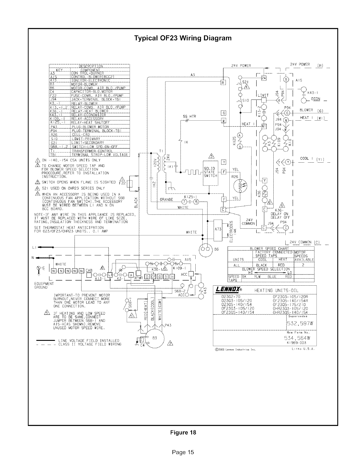
Typical OF23 Wiring Diagram
A ON 140,154 CSA UNTTS ONLY
_TO CHANGE MOTOR SPEED TAP AND
FOR BLOWER SPEED GELECIION
PROCEDURE,REFER TO INSTALLATION
INSTRUCTION, _
A SWITCH OPENS WHEN FLAME IS SIGHTED F22
A $21 USED ON OHR23 SERIES ONLY
_WHEN AN ACCESSORY IS BEING USED IN A
CONTINUOUS PAN APPLICATION WITHOUT S6B
(CONTINUOUS FAN SWITCH].THE ACCESSORY
MUST BE WIRED BETWEEN LI AND N ON
BCC BOARD.
NOTEIF ANY WIRE IN THIS APPLIANCE IS REPLACED,
IT MUST BE REPLACED WITH WIRE OF LIKE SIZE,
RATING,INSULATION ¸THICKNESS AND TERMINATION
SET THERMOSTAT HEAl ¸¸ ANTICIPATION
FOR 023/OF23/OHR23 UNITS.. 0,1 AMP
ORANGE
SS H[R
KE25-1
WHILE
WHITE :s
i:iJ
24V POWER
UNIIS
ILIMIT
I
L
P94
T
_p ECON
BLOWER (G)
HEAT I (WI)
A
K56
DELAY ON I
DELAY OFF I
LzAv COMMON (C/
SLOWER SPEED CHART
FACTORY CONNECTED MOTOR
SPEED TAPS SPEEDS
AVAILABLE
ALL 2
BLOWER SPEED SELEC]ION
HI LO
SPEED IBK YLW BLUE RED
TAPS I
IB
[
EOUIPMENT
GROUND
IMPORTANT-TO PREVENT MOTOR
BURNOUT,NEVER CONNECT MORE
THAN ONE MOTOR LEAD TO ANY
ONE CONNECTION.
L_ IF HEATING AND LOW SPEED
ARE TG BE GAME,CGNNECT
JUMPER BETWEEN $68-1 AND
AI5 H(AS SHOWN).REMOVE
UNUSED MOTOR SPEED WIRE.
ILINE VOLTAGE FIELD INSTALLED
.... CLASS II VOLTAGE FIELD WIRING
I._IIRUA® HEARING UNIIS OIL
02302=70 0F2305 105/120R
02303 105/E 20 DF2505- ] _-0/I!:i4R
02505 140/E 54 OF 2505 = 175/210
0F2505- 105/120 OHR25Q5 105/120
0F2505-140/154 O_ R2505 = 140/154
N_w Form No,
554,564W
41969005
(_)zoo_Le_ _d_ fr_s la_ Lfho U.S. A
Figure 18
Page 15
Beforestartingunit,makesuretheoiltankisadequately
filledwithcleanNo,1or No, 2 furnace oil,
NOTE -Water, rust or other contaminants in oil supply sys-
tem will cause malfunction and failure of the internal parts
of the fuel unit.
CAUTION
Ai, CAUTION
1- Set thermostat for heating demand and turn on electri-
cal supply to unit,
2- Check initial air adjustment, All units are equipped with
an air adjustment dial on the right side of the burner.
See burner parts arrangement illustration.
3- Turn unit on. Place a can or container under the bleed
port located on the fuel pump. Loosen nut on bleed
port to release air and oil mixture from fuel line, Allow
mixture to escape until a steady stream of oil is emitted
from the port, Drain at least 1/2 pint of oil from the
pump, Retighten nut on bleed port.
NOTE -A two-line fuel system will normally bleed itself
by forcing air back to the tank through the return line.
This type of bleeding procedure is not necessary.
4- If burner fails to start, push reset button on primary
safety control and the burner motor reset button once.
See part arrangement illustration,
CAUTION
5- If burner fails to light again, refer to the troubleshooting
section in this manual,
A - Fuel Pump Pressure Adjustment
Measure fuel pump pressure with unit off. Attach pressure
gauge to pump outlet, Turn unit on and check pressure and
compare to table 3, Adjust if necessary,
B - Temperature Rise Adjustment
To measure temperature rise, place plenum thermometers
in warm air and return air plenums, Locate thermometer in
warm air plenum where thermometer will not "see" the heat
exchanger to prevent it from picking up radiant heat. Set
thermostat to its highest setting to start unit, After plenum
thermometers have reached their highest and steadiest
readings, subtract the readings. The difference in tempera-
tures in the supply and return air plenums should approxi-
mate the temperatures listed in table 5 and the appliance
rating plate. If not, adjust the blower motor pulley to adjust
the blower speed.
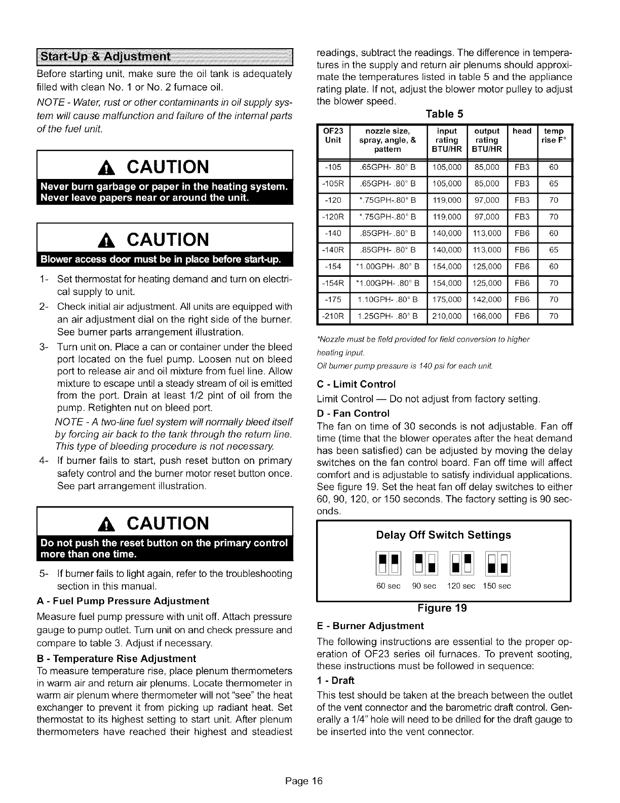
Table 5
OF23 nozzle size, input output head temp
Unit spray, angle, & rating rating rise F°
pattern BTU/HR BTU/HR
-105 .65GPH-.80 ° B 105,000 85,000 FB3 60
-105R .65GPH-.80 ° B 105,000 85,000 FB3 65
-120 *.75GPH-.80 ° B 119,000 97,000 FB3 70
-120R *.75GPH-.80 ° B 119,000 97,000 FB3 70
-140 .85GPH-.80 ° B 140,000 113,000 FB6 60
-140R .85GPH-.80 ° B 140,000 113,000 FB6 65
-154 *I.00GPH-.80 ° B 154,000 125,000 FB6 60
-154R *I.00GPH-.80 ° B 154,000 125,000 FB6 70
-175 1.10GPH- .80 ° B 175,000 142,000 FB6 70
-210R 1.25GPH- .80 ° B 210,000 166,000 FB6 70
*Nozzle must be field provided for field conversion to higher
heating input.
Oil burner pump pressure is !40 psi for each unit.
C - Limit Control
Limit Control -- Do not adjust from factory setting.
D - Fan Control
The fan on time of 30 seconds is not adjustable, Fan off
time (time that the blower operates after the heat demand
has been satisfied) can be adjusted by moving the delay
switches on the fan control board, Fan off time will affect
comfort and is adjustable to satisfy individual applications.
See figure 19, Set the heat fan off delay switches to either
60, 90, 120, or 150 seconds. The factory setting is 90 sec-
onds.
Delay Off Switch Settings
60 sec 90 sec 120 sec 150 sec
Figure 19
E- Burner Adjustment
The following instructions are essential to the proper op-
eration of OF23 series oil furnaces, To prevent sooting,
these instructions must be followed in sequence:
1 - Draft
This test should be taken at the breach between the outlet
of the vent connector and the barometric draft control. Gen-
erally a 1/4" hole will need to be drilled for the draft gauge to
be inserted into the vent connector.
Page 16
A minimumof 0,03draftmustbeestablishedwithoutthe
burnerinoperation,Withtheburnerinoperation,thedraft
shouldbe0.04to 0.05.ThisisVERYcriticalto theflame
retentionheadburners.
Oilfurnaceinstallationsalsorequirecarefulinspectionto
makesurethechimneyisingoodshapeandcanaccom-
modatethe productsof combustion.Thetemperaturein
theunconditionedspacewillalsoaffectthedraftif longvent
connectorsareallowedtogettoocold,
2- OverfireDraft
Thistestshouldbetakenwiththeburnerinoperation.Re-
movethescrewfromthecenteroftheinspectiondoor.In-
sertyourdraftgaugeintothehole,
A readingoftheoverfiredraftshouldbe0,02lessthanthe
readingfoundintheventconnector.Ifapositivereadingis
seenatthispoint,thecombustionfanispumpingtoomuch
airintotheheatexchanger,Makethenecessaryadjust-
mentsattheairadjustmentdial,
3- SmokeTest
Thesmoketestshouldbetakenattheholedrilledinstep1,
Usingasmoketestgunadjusttheairinletshuttersothat
youwillhavejustatraceofsmoke.Somewherebetween0
and#1smoke,Thisisthestarting point, Do not stop here.
4 - CO2 Test
Again, take the sample at the vent pipe, With the unit firing
at a trace of smoke, take a sample of the CO2,
From the results of this test, a "window of operation" will be
determined, This window of operation establishes some
tolerance. The tolerance the installer builds in provides
room within the set-up for those things which might affect
combustion, Those things which might affect combustion
can then do so without causing the unit to start sooting/
smoking. Things which might affect combustion include a
nozzle going bad, draft that changes during different clima-
tic conditions, dirty oil, dirt obstructing the air inlet, etc,
To build in a "window of operation," set up the burner to be
2% less in CO2. For example, if you find a reading of 12%
CO2, adjust the air inlet shutter to increase the air and drop
the CO2 to 10%.
5 - Retest the Smoke
With a drop in the CO2 and increase in the air you should
see that the smoke has returned to 0,
6- Retest the Overfire Draft
This test serves to confirm that you have not increased the
air too much, Again you do not want a positive pressure at
the test port. It should still be 0.02 less than the draft pres-
sure reading taken at the breach. You may need to
increase the stack draft by adjusting the barometric draft
control,
7 - Stack Temperature
Take a stack temperature reading in the vent pipe, Subtract
the room air temperature from the stack temperature. This
will give you the net stack temperature. Use the efficiency
charts provided in most C02 analyzers to determine fur-
nace efficiency.
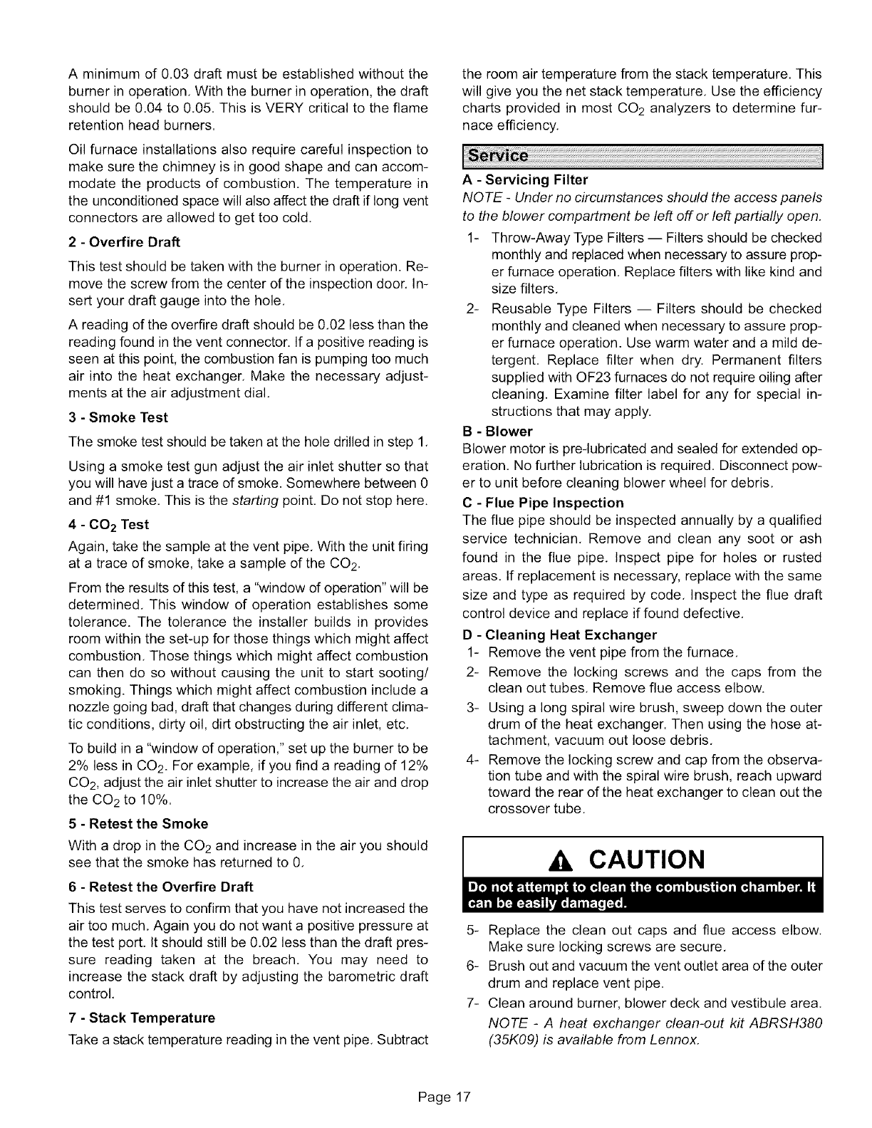
A - Servicing Filter
NOTE -Under no circumstances should the access panels
to the blower compartment be left off or left partially open.
1- Throw-Away Type Filters -- Filters should be checked
monthly and replaced when necessary to assure prop-
er furnace operation, Replace filters with like kind and
size filters,
2- Reusable Type Filters -- Filters should be checked
monthly and cleaned when necessary to assure prop-
er furnace operation. Use warm water and a mild de-
tergent. Replace filter when dry. Permanent filters
supplied with OF23 furnaces do not require oiling after
cleaning. Examine filter label for any for special in-
structions that may apply,
B - Blower
Blower motor is pre-lubricated and sealed for extended op-
eration. No further lubrication is required. Disconnect pow-
er to unit before cleaning blower wheel for debris,
C - Flue Pipe Inspection
The flue pipe should be inspected annually by a qualified
service technician, Remove and clean any soot or ash
found in the flue pipe, Inspect pipe for holes or rusted
areas, If replacement is necessary, replace with the same
size and type as required by code, Inspect the flue draft
control device and replace if found defective,
D - Cleaning Heat Exchanger
1- Remove the vent pipe from the furnace,
2- Remove the locking screws and the caps from the
clean out tubes, Remove flue access elbow.
3- Using a long spiral wire brush, sweep down the outer
drum of the heat exchanger. Then using the hose at-
tachment, vacuum out loose debris,
4- Remove the locking screw and cap from the observa-
tion tube and with the spiral wire brush, reach upward
toward the rear of the heat exchanger to clean out the
crossover tube,
CAUTION
5- Replace the clean out caps and flue access elbow,
Make sure locking screws are secure,
6- Brush out and vacuum the vent outlet area of the outer
drum and replace vent pipe.
7- Clean around burner, blower deck and vestibule area.
NOTE -A heat exchanger clean-out kit ABRSH380
(35K09) is available from Lennox.
Page 17
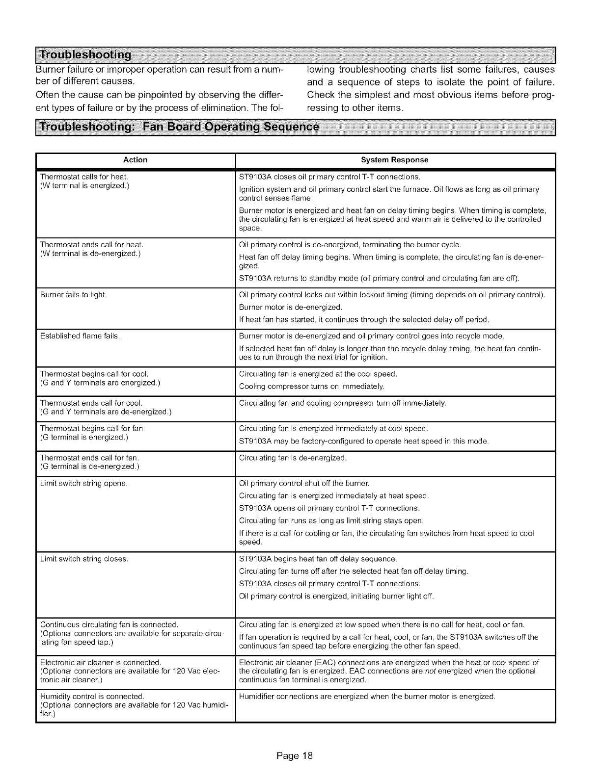
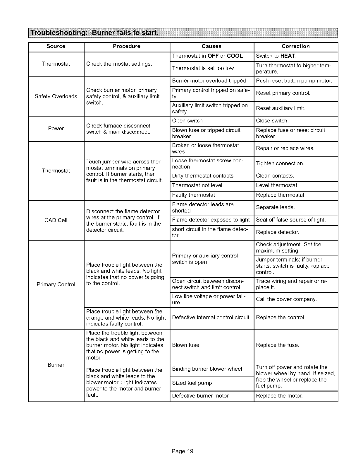
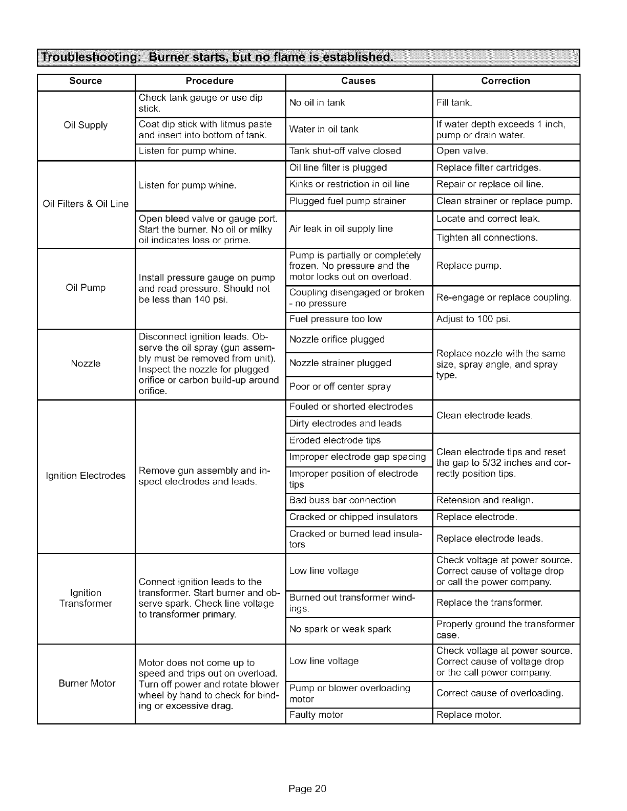
Burnerfailureorimproperoperationcanresultfromanum-
berofdifferentcauses,
Oftenthecausecanbepinpointedbyobservingthediffer-
enttypesoffailureorbytheprocessofelimination.Thefol-
lowingtroubleshootingchartslist somefailures,causes
anda sequenceof stepsto isolatethe pointof failure.
Checkthesimplestandmostobviousitemsbeforeprog-
ressingtootheritems.
Action
Thermostat calls for heat.
(W terminal is energized.)
Thermostat ends call for heat.
(W terminal is de-energized.)
Burner fails to light.
Established flame fails.
Thermostat begins call for cool.
(G and Y terminals are energized.)
Thermostat ends call for cool.
(G and Y terminals are de-energized.)
System Response
ST9103A closes oil primary control T-T connections.
Ignition system and oil primary control start the furnace. Oil flows as long as oil primary
control senses flame.
Burner motor is energized and heat fan on delay timing begins. When timing is complete.
the circulating fan is energized at heat speed and warm air is delivered to the controlled
space.
Oil primary control is de-energized, terminating the burner cycle.
Heat fan off delay timing begins. When timing is complete, the circulating fan is de-ener-
gized,
ST9103A returns to standby mode (oil primary control and circulating fan are off).
Oil primary control locks out within lockout timing (timing depends on oil primary control).
Burner motor is de-energized,
If heat fan has started, it continues through the selected delay off period.
Burner motor is de-energized and oil primary control goes into recycle mode.
If selected heat fan off delay is longer than the recycle delay timing, the heat fan contin-
ues to run through the next trial for ignition.
Circulating fan is energized at the cool speed.
Cooling compressor turns on immediately.
Circulating fan and cooling compressor turn off immediately.
Thermostat begins call for fan. Circulating fan is energized immediately at cool speed.
(G terminal is energized.) ST9103A may be factory-configured to operate heat speed in this mode.
Thermostat ends call for fan. Circulating fan is de-energized.
(G terminal is de-energized.)
Limit switch string opens.
Limit switch string closes.
Oil primary control shut off the burner.
Circulating fan is energized immediately at heat speed.
ST9103A opens oil primary control T-T connections.
Circulating fan runs as long as limit string stays open.
If there is a call for cooling or fan, the circulating fan switches from heat speed to cool
speed.
ST9103A begins heat fan off delay sequence.
Circulating fan turns off after the selected heat fan off delay timing.
ST9103A closes oil primary control T-T connections.
Oil primary control is energized, initiating burner light off.
Continuous circulating fan is connected. Circulating fan is energized at low speed when there is no call for heat, cool or fan.
(Optional connectors are available for separate circu- If fan operation is required by a call for heat, cool, or fan, the ST9103A switches off the
lating fan speed tap.) continuous fan speed tap before energizing the other fan speed.
Electronic air cleaner is connected. Electronic air cleaner (EAC) connections are energized when the heat or cool speed of
(Optional connectors are available for 120 Vac elec- the circulating fan is energized. EAC connections are not energized when the optional
tronic air cleaner.) continuous fan terminal is energized.
Humidity control is connected. Humidifier connections are energized when the burner motor is energized.
(Optional connectors are available for 120 Vac humidi-
fier.)
Page 18
Source
Thermostat
Safety Overloads
Power
Thermostat
CAD Cell
Primary Control
Burner
Procedure Causes
Thermostat in OFF or COOL
Check thermostat settings.
Check burner motor, primary
safety control, & auxiliary limit
switch.
Check furnace disconnect
switch & main disconnect.
Touch jumper wire across ther-
mostat terminals on primary
control. If burner starts, then
fault is in the thermostat circuit.
Disconnect the flame detector
wires at the primary control. If
the burner starts, fault is in the
detector circuit.
Place trouble light between the
black and white leads. No light
indicates that no power is going
to the control.
Place trouble light between the
orange and white leads. No light
indicates faulty control.
Place the trouble light between
the black and white leads to the
burner motor. No light indicates
that no power is getting to the
motor.
Place trouble light between the
black and white leads to the
blower motor. Light indicates
power to the motor and burner
fault.
Thermostat is set too low
Burner motor overload tripped
Primary control tripped on safe-
ty
Auxiliary limit switch tripped on
safety
Open switch
Blown fuse or tripped circuit
breaker
Broken or loose thermostat
wires
Loose thermostat screw con-
nection
Dirty thermostat contacts
Thermostat not level
Faulty thermostat
Flame detector leads are
shorted
Flame detector exposed to light
short circuit in the flame detec-
tor
Primary or auxiliary control
switch is open
Open circuit between discon-
nect switch and limit control
Low line voltage or power fail-
ure
Defective internal control circuit
Blown fuse
Correction
Switch to HEAT.
Turn thermostat to higher tem-
perature.
Push reset button pump motor.
Reset primary control.
Reset auxiliary limit.
Close switch.
Replace fuse or reset circuit
breaker.
Repair or replace wires.
Tighten connection.
Clean contacts.
Level thermostat.
Replace thermostat.
Separate leads.
Seal off false source of light.
Replace detector.
Check adjustment. Set the
maximum setting.
Jumper terminals; if burner
starts, switch is faulty, replace
control.
Trace wiring and repair or re-
place it.
Call the power company.
Replace the control.
Replace the fuse.
Binding burner blower wheel
Sized fuel pump
Defective burner motor
Turn off power and rotate the
blower wheel by hand. If seized,
free the wheel or replace the
fuel pump.
Replace the motor.
Page 19
Source
Oil Supply
Oil Filters & Oil Line
Oil Pump
Nozzle
Ignition Electrodes
Ignition
Transformer
Burner Motor
Procedure
Check tank gauge or use dip
stick.
Coat dip stick with litmus paste
and insert into bottom of tank.
Listen for pump whine.
Listen for pump whine.
Open bleed valve or gauge port.
Start the burner. No oil or milky
oil indicates loss or prime.
Install pressure gauge on pump
and read pressure. Should not
be less than 140 psi.
Disconnect ignition leads. Ob-
serve the oil spray (gun assem-
bly must be removed from unit).
Inspect the nozzle for plugged
orifice or carbon build-up around
orifice.
Remove gun assembly and in-
spect electrodes and leads.
Connect ignition leads to the
transformer. Start burner and ob-
serve spark. Check line voltage
to transformer primary.
Motor does not come up to
speed and trips out on overload.
Turn off power and rotate blower
wheel by hand to check for bind-
ing or excessive drag.
Causes
No oil in tank
Water in oil tank
Tank shut-off valve closed
Oil line filter is plugged
Kinks or restriction in oil line
Plugged fuel pump strainer
Air leak in oil supply line
Pump is partially or completely
frozen. No pressure and the
motor locks out on overload.
Correction
Fill tank.
If water depth exceeds 1 inch,
pump or drain water.
Open valve.
Replace filter cartridges.
Repair or replace oil line.
Clean strainer or replace pump.
Locate and correct leak.
Tighten all connections.
Replace pump.
Coupling disengaged or broken Re-engage or replace coupling.
- no pressure
Fuel pressure too low Adjust to 100 psi.
Nozzle orifice plugged
Nozzle strainer plugged
Poor or off center spray
Fouled or shorted electrodes
Dirty electrodes and leads
Eroded electrode tips
Improper electrode gap spacing
Improper position of electrode
tips
Bad buss bar connection
Cracked or chipped insulators
Cracked or burned lead insula-
tors
Low line voltage
Burned out transformer wind-
ings.
No spark or weak spark
Low line voltage
Pump or blower overloading
motor
Faulty motor
Replace nozzle with the same
size, spray angle, and spray
type.
Clean electrode leads.
Clean electrode tips and reset
the gap to 5/32 inches and cor-
rectly position tips.
Retension and realign.
Replace electrode.
Replace electrode leads.
Check voltage at power source.
Correct cause of voltage drop
or call the power company.
Replace the transformer.
Properly ground the transformer
case.
Check voltage at power source.
Correct cause of voltage drop
or the call power company.
Correct cause of overloading.
Replace motor.
Page 20
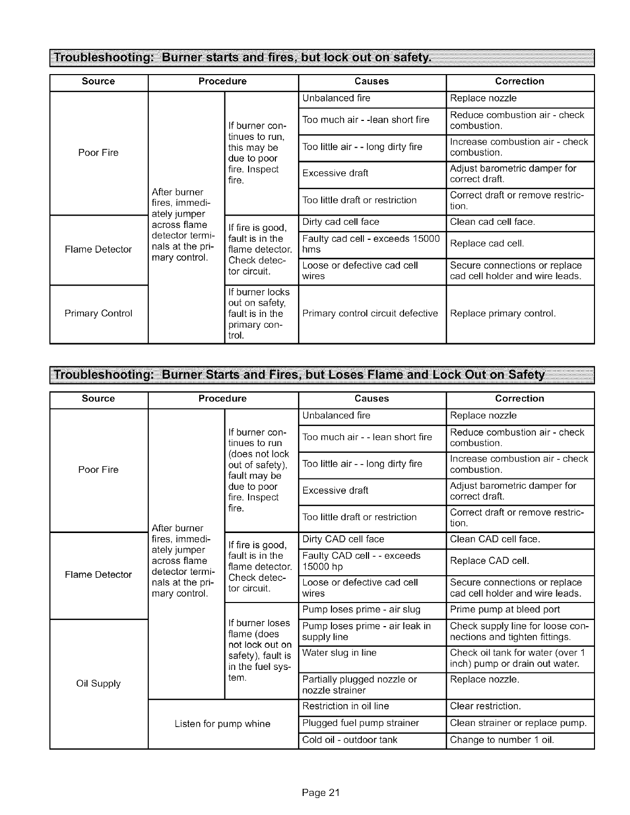
Source Procedure
Poor Fire
Flame Detector
Primary Control
After burner
fires, immedi-
ately jumper
across flame
detector termi-
nals at the pri-
mary control.
If burner con-
tinues to run,
this may be
due to poor
fire. Inspect
fire.
If fire is good,
fault is in the
flame detector.
Check detec-
tor circuit.
If burner locks
out on safety,
fault is in the
primary con-
trol.
Causes
Unbalanced fire
Too much air - -lean short fire
Too little air - - long dirty fire
Excessive draft
Too little draft or restriction
Dirty cad cell face
Faulty cad cell - exceeds 15000
hms
Loose or defective cad cell
wires
Primary control circuit defective
Correction
Replace nozzle
Reduce combustion air - check
combustion.
Increase combustion air - check
combustion.
Adjust barometric damper for
correct draft.
Correct draft or remove restric-
tion.
Clean cad cell face.
Replace cad cell.
Secure connections or replace
cad cell holder and wire leads.
Replace primary control.
Source Procedure
Poor Fire
Flame Detector
Oil Supply
After burner
fires, immedi-
ately jumper
across flame
detector termi-
nals at the pri-
mary control,
If burner con-
tinues to run
(does not lock
out of safety),
fault may be
due to poor
fire. Inspect
fire.
If fire is good,
fault is in the
flame detector.
Check detec-
tor circuit.
If burner loses
flame (does
not lock out on
safety), fault is
in the fuel sys-
tem.
Listen for pump whine
Causes
Unbalanced fire
Too much air - - lean short fire
Too little air - - long dirty fire
Excessive draft
Too little draft or restriction
Dirty CAD cell face
Faulty CAD cell - - exceeds
15000 h p
Loose or defective cad cell
wires
Pump loses prime - air slug
Pump loses prime - air leak in
supply line
Water slug in line
Partially plugged nozzle or
nozzle strainer
Restriction in oil line
Plugged fuel pump strainer
Cold oil - outdoor tank
Correction
Replace nozzle
Reduce combustion air - check
combustion.
Increase combustion air - check
combustion.
Adjust barometric damper for
correct d raft.
Correct draft or remove restric-
tion.
Clean CAD cell face.
Replace CAD cell.
Secure connections or replace
cad cell holder and wire leads.
Prime pump at bleed port
Check supply line for loose con-
nections and tighten fittings.
Check oil tank for water (over 1
inch) pump or drain out water.
Replace nozzle.
Clear restriction.
Clean strainer or replace pump.
Change to number 1 oil.
Page 21
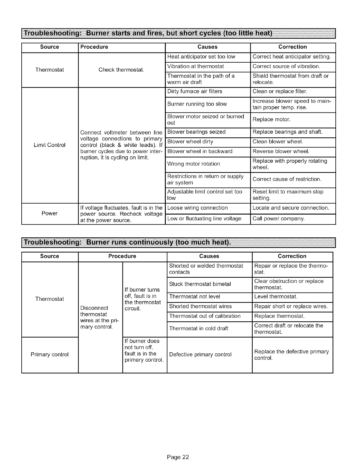
Source Procedure
Thermostat
Limit Control
Power
Check thermostat.
Connect voltmeter between line
voltage connections to primary
control (black & white leads). If
burner cycles due to power inter-
ruption, it is cycling on limit.
If voltage fluctuates, fault is in the
power source. Recheck voltage
at the power source.
Causes
Heat anticipator set too low
Vibration at thermostat
Thermostat in the path of a
warm air draft
Dirty furnace air filters
Burner running too slow
Blower motor seized or burned
out
Blower bearings seized
Blower wheel dirty
Blower wheel in backward
Wrong motor rotation
Restrictions in return or supply
air system
Adjustable limit control set too
low
Loose wiring connection
Low or fluctuating line voltage
Correction
Correct heat anticipator setting.
Correct source of vibration.
Shield thermostat from draft or
relocate.
Clean or replace filter.
Increase blower speed to main-
tain proper temp. rise.
Replace motor.
Replace bearings and shaft.
Clean blower wheel.
Reverse blower wheel.
Replace with properly rotating
wheel.
Correct cause of restriction.
Reset limit to maximum stop
setting.
Locate and secure connection.
Call power company.
Source Procedure
Thermostat
Primary control
Disconnect
thermostat
wires at the pri-
mary control.
If burner turns
off, fault is in
the thermostat
circuit.
If burner does
not turn off,
fault is in the
primary control.
Causes
Shorted or welded thermostat
contacts
Stuck thermostat bimetal
Thermostat not level
Shorted thermostat wires
Thermostat out of calibration
Thermostat in cold draft
Defective primary control
Correction
Repair or replace the thermo-
stat.
Clear obstruction or replace
thermostat.
Level thermostat.
Repair short or replace wires.
Replace thermostat.
Correct draft or relocate the
thermostat.
Replace the defective primary
control.
Page 22
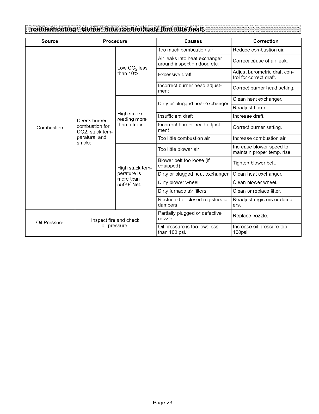
Source Procedure
Combustion
Oil Pressure
Check burner
combustion for
CO2, stack tem-
perature, and
smoke
Low CO 2 less
than 10%.
Causes
Too much combustion air
Air leaks into heat exchanger
around inspection door, etc.
Excessive draft
Incorrect burner head adjust-
ment
Dirty or plugged heat exchanger
High smoke Insufficient draft
reading more
than a trace. Incorrect burner head adjust-
ment
Too little combustion air
Too little blower air
High stack tem-
perature is
more than
550"F Net.
Inspect fire and check
oil pressure.
Blower belt too loose (if
equipped)
Dirty or plugged heat exchanger
Dirty blower wheel
Dirty furnace air filters
Restricted or closed registers or
dampers
Partially plugged or defective
nozzle
Oil pressure is too low: less
than 100 psi.
Correction
Reduce combustion air.
Correct cause of air leak.
Adjust barometric draft con-
trol for correct draft.
Correct burner head setting.
Clean heat exchanger.
Readjust burner.
Increase d raft.
Correct burner setting.
Increase combustion air.
Increase blower speed to
maintain proper temp. rise.
Tighten blower belt.
Clean heat exchanger.
Clean blower wheel.
Clean or replace filter.
Readjust registers or damp-
ers.
Replace nozzle.
Increase oil pressure top
100psi.
Page 23
