LENNOX Air Conditioner/heat Pump(outside Unit) Manual L0806427
User Manual: LENNOX LENNOX Air conditioner/heat pump(outside unit) Manual LENNOX Air conditioner/heat pump(outside unit) Owner's Manual, LENNOX Air conditioner/heat pump(outside unit) installation guides
Open the PDF directly: View PDF ![]() .
.
Page Count: 2
,_)2005 Lennox Industries Inc.
Dallas, Texas, USA
KITS COMMON TO COOLING
AND HEAT PUMP EQUIPMENT
TeCh n ical
blications
Litho U.S.A.
505,002M
04/2005 LOSS OF CHARGE KIT
INSTALLATION INSTRUCTIONS FOR LOSS OF CHARGE KIT (LB-110135 /84M23)
USED WITH CONDENSING UNITS AND HEAT PUMPS
Package 1 of 1 contains:
1 - Loss of charge switch ($24)
2 - Wire nuts
1 - Valve depressor tee fitting
The loss of charge kit (LB-110135A/84M23) is used with
all condensing units and heat pumps which use either
R-22 or R-410A refrigerant. The loss of charge switch
protects the system compressor from damage due to a
loss of charge, The single-pole /single-throw, normally
closed switch is permanently adjusted to open at 25 psig
(+5 psig), The switch automatically resets (closes) at 55
psig (+5 psig),
WARNING
NOTE -The depressor tee fitting provided with this kit is
used to install the loss of charge switch on the liquid line
service valve.
1 - Disconnect power to unit,
2 - Install the provided loss of charge switch on an open
port (no valve core) of the provided valve depressor
tee fitting,
NOTE -The pressure switch must be installed
before the depressor tee fitting is installed in
order to avoid refrigerant loss.
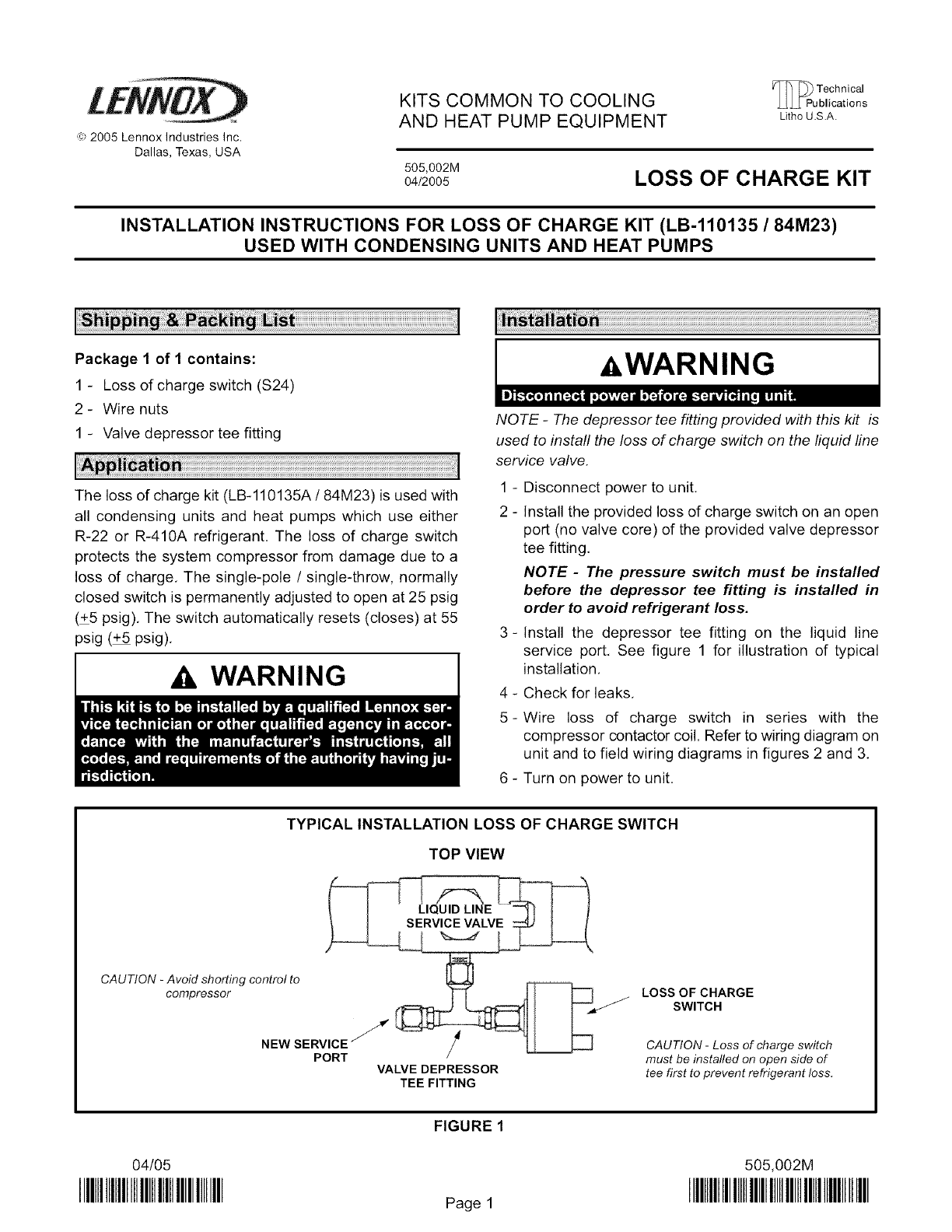
3- Install the depressor tee fitting on the liquid line
service port, See figure 1 for illustration of typical
installation,
4 - Check for leaks,
5-Wire loss of charge switch in series with the
compressor contactor coil. Refer to wiring diagram on
unit and to field wiring diagrams in figures 2 and 3,
6 - Turn on power to unit,
TYPICAL INSTALLATION LOSS OF CHARGE SWITCH
TOP VIEW
_-=_LIQU ID LINE
t ! SERVICE VALVE :_ I /
CAUTION "compressorAV°idshorting controINEwtoSERViCE_
PORT VALVE DEPRESSOR
TEE FITTING
LOSS OF CHARGE
SWITCH
CAUTION - Loss of charge switch
must be installed on open side of
tee first to prevent refrigerant loss.
04/05
IIIBIIIIIIIIIIIIIIIIIIIIIIIIIIIIIIIII
FIGURE 1
Page 1
505,002M
IIIBIIIIIIIIIIIIIIIIIIIIIIIIIIBIIIIIIIIIIIII
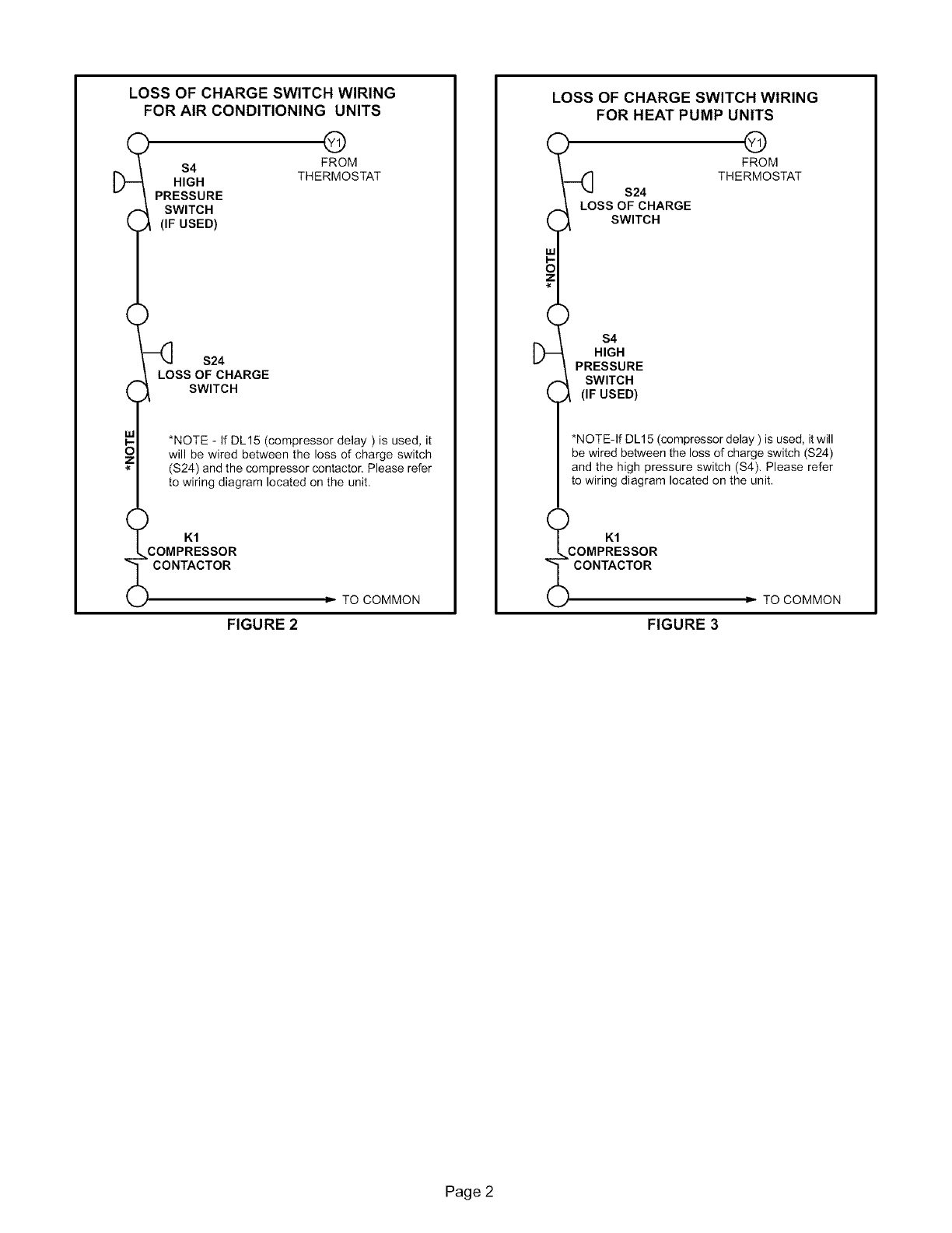
LOSS OF CHARGE SWITCH WIRING
FOR AIR CONDITIONING UNITS
RGE THE_R_MOoMsTAT
_1 *NOTE - If DL15 (compressor delay ) is used, it
O I will be wired between the loss of charge switch
I (S24) and the compressor contactor, Please refer
{_ to wiring diagram located on the unit.
_LcoMP#SSOR
k CONTACTOR
kJ = TO COMMON
FIGURE 2
LOSS OF CHARGE SWITCH WIRING
FOR HEAT PUMP UNITS
9 G
FROM
_] S24 THERMOSTAT
f _ LOS%_/vFTCFHARGE
H, H
\PRESSURE
,,_ SWITCH
.,_ (IF USED)
*NOTE-If DL15 (compressor delay ) is used, it will
be wired between the loss of charge switch ($24)
and the high pressure switch ($4), Please refer
to wiring diagram located on the unit.
K1
..COMPRESSOR
_ CONTACTOR = TO COMMON
FIGURE 3
Page 2
