LENNOX Air Conditioner/heat Pump(outside Unit) Manual L0806500
User Manual: LENNOX LENNOX Air conditioner/heat pump(outside unit) Manual LENNOX Air conditioner/heat pump(outside unit) Owner's Manual, LENNOX Air conditioner/heat pump(outside unit) installation guides
Open the PDF directly: View PDF ![]() .
.
Page Count: 28
,?c ' ' •
2008 lennox Industr_es Inc
Datias, Texas, USA
INSTALLATION
INSTRUCTIONS
S'ClassTM SPB*H4 Units
SPB036H4S41, SPB048H4S41 and
SPB060H4S41
HEAT PUMPS _ Technical
505,330M LLL[ Publications
02/08 Litho U.S.A.
Supersedes 06/07
RETAIN THESE INSTRUCTIONS
FOR FUTURE REFERENCE
Xk WARNING
CAUTION
IMPORTANT
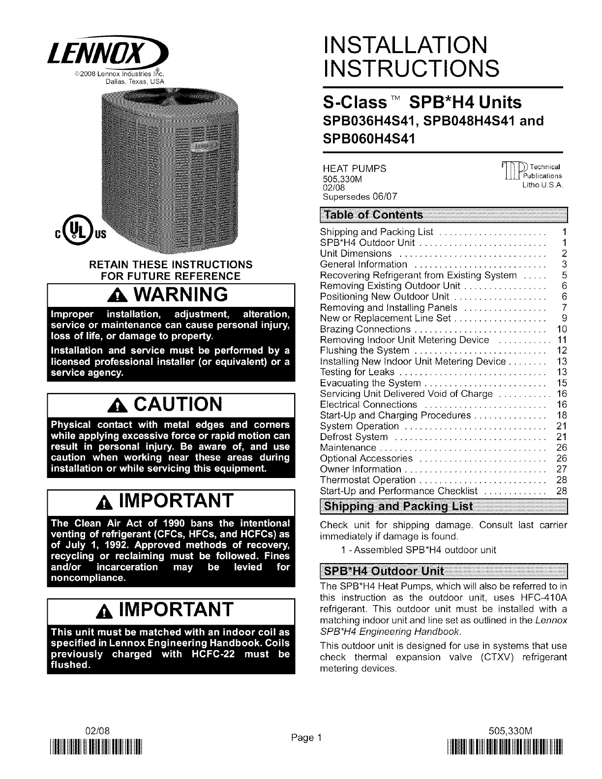
Shipping and Packing List ...................... 1
SPB*H4 Outdoor Unit .......................... 1
Unit Dimensions .............................. 2
General Information ........................... 3
Recovering Refrigerant from Existing System ..... 5
Removing Existing Outdoor Unit ................. 6
Positioning New Outdoor Unit ................... 6
Removing and Installing Panels ................. 7
New or Replacement Line Set ................... 9
Brazing Connections ........................... 10
Removing Indoor Unit Metering Device ........... 11
Flushing the System ........................... 12
Installing New Indoor Unit Metering Device ........ 13
Testing for Leaks .............................. 13
Evacuating the System ......................... 15
Servicing Unit Delivered Void of Charge ........... 16
Electrical Connections ......................... 16
Start-Up and Charging Procedures ............... 18
System Operation ............................. 21
Defrost System ............................... 21
Maintenance .................................. 26
Optional Accessories .......................... 26
Owner Information ............................. 27
Thermostat Operation .......................... 28
Start-Up and Performance Checklist ............. 28
Check unit for shipping damage. Consult last carrier
immediately if damage is found.
1 -Assembled SPB*H4 outdoor unit
IMPORTANT
The SPB*H4 Heat Pumps, which will also be referred to in
this instruction as the outdoor unit, uses HFC-410A
refrigerant. This outdoor unit must be installed with a
matching indoor unit and line set as outlined in the Lennox
SPB*H4 Engineering Handbook.
This outdoor unit is designed for use in systems that use
check thermal expansion valve (CTXV) refrigerant
metering devices.
02/08
IIIHIIIIIIIIIIIHIIIIIIIIIIIIIIIIII Page 1 505,330M
IIIIIIIIIIIIIIIIIIIIIIIIIIIIIIIIIIIIIIIIIIIIIIIIII

RUN
CAPACITOR
DEFROST
BOARD OUTDOORFAN
CONTACTOR COMPRESSOR
TOP VIEW
SUCTION LINE
• CONNECTION
LIQUID LINE
CONNECTION
REVERSING HIGH PRESSURE
VALVE SWITCH
FILTER DRIER/ VAPOR LINE
LIQUID LINE
CONNECTIONS
VAPOR VALVE AND
GAUGE PORT/SUCTION
LINE CONNECTIONS
SPB*H4 PARTS ARRANGEMENT
C
DISCHARGE AIR t D
LIQUID LINE
-_ --CONNECTION
ELECTRICAL
INLETS
/V VAPORLINE
JCONNECTION
4_1/4(1 4_8/4
08) (121)
i i t t
SIDE VIEW
0N'TSUPPORTFEET\ __FO
13-7/8
(352) @ @ @
7-3/4
(197)
l
3-1/4
(83) (689)
i: ° :j
2 (51)
\
1 (25)
I I i i
SIDE VIEW
-T
20-5/8
(524)
1
4-1/2
(114)
--T
3-5/8
(92)
BASE WITH ELONGATED LEGS
Model A B C D E F G H I J
SPB*H4-036 35 (889) 30-1/2 (775) 35 (889) 17-5/8 (448) 8-3/4 (222) 18 (457) 9 (229) 8-1/2 (216) 9 (229) 11-1/2 (292)
SPB*H4-048 45 (1143) 30-1/2 (775) 35 (889) 27-5/8 (702) 8-3/4 (222) 18 (457) 9 (229) 11-1/2 (292) 9 (229) 11-1/2 (292)
SPB*H4-060 39 (991) 30-1/2 (775) 35 (889) 27-5/8 (702) 11 (222) 18 (457) 10-1/2 (267) 13-1/2 (343) 10-1/2 (267) 13-1/2 (343)
505330M 02/08
Page 2

WARNING OPERATING SERVICE VALVES
The liquid and vapor line service valves are used for
removing refrigerant, flushing, leak testing, evacuating,
checking charge and charging,
Each valve is equipped with a service port which has a
factory-installed valve stem.
IMPORTANT
These instructions are intended as a general guide and do
not supersede local codes in any way. Consult authorities
who have jurisdiction before installation.
When servicing or repairing HVAC components, ensure
the fasteners are appropriately tightened. Table 1 shows
torque values for fasteners.
Table 1. Torque Requirements
Parts Recommended Torque
Service valve cap 8 ft.- lb. 11 NM
Sheet metal screws 16 in.- lb. 2 NM
Machine screws #10 28 in.- lb. 3 NM
Compressor bolts 90 in.- lb. 10 NM
Gauge port seal cap 8 ft.- lb. 11 NM
USING MANIFOLD GAUGE SETS
When checking the system charge, only use a manifold
gauge set that features low loss anti-blow back fittings.
See figure 2 for a typical manifold gauge connection setup,
Manifold gauge sets used with HFC-410A refrigerant
systems must be capable of handling the higher system
operating pressures. The gauges should be rated for use
with pressures of 0 - 800 on the high side and a low side of
30" vacuum to 250 psi with dampened speed to 500 psi.
Gauge hoses must be rated for use at up to 800 psi of
pressure with a 4000 psi burst rating,
I/6 TURN 1/12 TURN
9
8 4
Figure 1Cap Tightening Distances
IMPORTANT
To Access Angle-Type Service Port:
A service port cap protects the service port core from
contamination and serves as the primary leak seal,
1. Remove service port cap with an appropriately sized
wrench.
2. Connect gauge to the service port,
3. When testing is completed, replace service port cap and
tighten as follows:
•With Torque Wrench: Finger tighten and then
tighten per table 1,
• Without Torque Wrench: Finger tighten and use an
appropriately sized wrench to turn an additional
1/6 turn clockwise as illustrated in figure 1.
Page 3
SPB*H4 SERIES

DISTRIBUTOR
CBECK REV S' :UV E
EXPANSION VALVE _ \
DR,ER O% tOR "-
LOW HIGH MUFFLER
PRESSURE PRESSURE ___ ]
;g2 ° V'A;°2
_ CHECK EXPANSION VALVE --
NOTE - ARROWS INDICATE DIRECTION
OF REFRIGERANT FLOW.
INDOOR UNIT
INDOOR
COIL
Figure 2. Typical Manifold Gauge Connection Setup
ToOpen and CloseAngle-TypeServiceValve:
A valve stem cap protects the valve stem from
contamination and assures a leak-free seal.
1. Remove stem cap with an appropriately sized wrench.
2. Use a service wrench with a hex-head extension
(3/16" for liquid-line valve sizes and 5/16" for
vapor-line valve sizes) to back the stem out
counterclockwise as far as it will go.
3. Replace the stem cap and tighten as follows:
•With Torque Wrench: Tighten finger tight and then
tighten per table 1.
• Without Torque Wrench: Finger tighten and use an
appropriately sized wrenched to turn an additional
1/12 turn clockwise as illustrated in figure 1.
SERVICE PORT
CAP_-_
_L_ SERVICE PORT
SERVICE PORT /"
CORE (VALVESTEMSBOWN
I _ //_/_ _ _ CLOSED) INSERT HEX
WRENCH HERE
FRONT-SEATED
TO INDOOR
UNIT
TO OUTDOOR UNIT J J CLOSED TO BOTH INDOOR
AND OUTDOOR UNITS
Figure 3. Angle-Type Service Valve
(Font-Seated Closed)
NOTE -A label with specific torque requirements may be
affixed to the stem cap. If the label is present, use the
specified torque.
NOTE- To prevent stripping of the cap, the wrench should
be appropriately sized and fit snugly over the cap before
tightening the cap.
SERVICE PORT CAP
SERVICE PORT SERVICE PORT
CORE
OPEN TO BOTH (VALVE STEM SHOWN OPEN)
INDOOR AND INSERT HEX WRENCH HERE
OUTDOOR UNITS
TO INDOOR
UNIT
STEM CAP
TO OUTDOOR UNIT
Figure 4. Angle-Type Service Valve
(Back-Seated Opened)
To Access Bali-Type Service Port:
A service port cap protects the service port core from
contamination and serves as the primary leak seal.
1. Remove service port cap with an appropriately sized
wrench.
2. Connect gauge to the service port.
3. When testing is completed, replace service port cap and
tighten as follows:
•With Torque Wrench: Finger tighten and then
tighten per table 1.
•Without Torque Wrench: Finger tighten and use an
appropriately sized wrench to turn an additional
1/6 turn clockwise as illustrated in figure 1.
505330M 02/08
Page 4

OPEN TO LINE SET WHEN VALVE IS CLOSED,
TO BOTH LINE SET AND UNIT WHEN VALVE IS
OPEN.
TO OPEN ROTATE STEM
COUNTERCLOCKWISE 90° .
TO CLOSE ROTATE STEM
CLOCKWISE 90 ° .
TO INDOOR UNIT
BALL (SHOWN
CLOSED)
VALVE
STEM
CORE
SERVICE PORT CAP
TO OUTDOOR UNIT STEM CAP
Figure 5. Bali-Type Service Valve
ToOpen and Close Bali-TypeServiceValve:
A valve stem cap protects the valve stem from
contamination and assures a leak-free seal.
1. Remove stem cap with an appropriately sized wrench.
2. Use an appropriately sized wrenched to open. To open
valve, roate stem counterclockwise 90°, To close
rotate stem clockwise 90°.
3. Replace the stem cap and tighten as follows:
•With Torque Wrench: Finger tighten and then
tighten per table 1.
• Without Torque Wrench: Finger tighten and use an
appropriately sized wrench to turn an additional
1/12 turn clockwise as illustrated in figure 1.
NOTE -A label with specific torque requirements may be
affixed to the stem cap. If the label is present, use the
specified torque.
Remove existing HCFC-22 refrigerant using one of the
following procedures:
METHOD 1:
If the existing outdoor unit is not equipped with shut-off
valves, or if the unit is not operational and you plan to use
the existing HCFC-22 to flush the system.
NOTE -Use recovery machine instructions for specific
setup requirements.
1. Disconnect all power to the existing outdoor unit.
2. Connect to the existing unit a gauge set, clean
recovery cylinder and a recovery machine. Use the
instructions provided with the recovery machine on
how to setup the connections.
3. Remove all HCFC-22 refrigerant from the existing
system. Check gauges after shutdown to confirm that
the entire system is completely void of refrigerant.
RECOVERY MACHINE MANIFOLD GAUGES
/
OUTDOOR UNIT
Figure 6. Typical Refrigerant Recovery
(Method 1)
NOTE -Use recovery machine instructions for specific
setup requirements.
METHOD 2:
Use this method if the existing outdoor unit is equipped
with manual shut-off valves, and plan on using new
HCFC-22 refrigerant to flush the system.
IMPORTANT: Some system configurations may contain
higher than normal refrigerant charge due to either large
internal coil volumes, and/or long line sets. The following
conditions may cause the compressor to stop functioning:
The following devices could prevent full system charge
recovery into the outdoor unit:
• Outdoor unit's high or low-pressure switches (if
applicable) when tripped can cycled the compressor
OFF.
• Compressor can stop pumping due to tripped internal
pressure relief valve.
• Compressor has internal vacuum protection that is
designed to unload the scrolls (compressor stops
pumping) when the pressure ratio meets a certain
value or when the suction pressure is as high as 20
psig. (Compressor suction pressures should never be
allowed to go into a vacuum. Prolonged operation at
low suction pressures will result in overheating of the
scrolls and permanent damage to the scroll tips, drive
bearings and internal seals).
Once the compressor can not pump down to a lower
pressure due to one of the above system conditions, shut
off the suction valve. Turn OFF the main power to unit and
use a recovery machine to recover any refrigerant left in
the indoor coil and line set.
Perform the following task:
1. Start the existing HCFC-22 system in the cooling
mode and close the liquid line valve.
2. Pump as much of the existing HCFC-22 refrigerant
with the compressor back into the outdoor unit until
you have reached the limitations of the outdoor
system. Turn the outdoor unit main power OFF and
use a recovery machine to remove the remaining
refrigerant in the system.
Page 5
SPB*H4 SERIES

NOTE -It may be necessary to bypass the low pressure
switches if equipped to ensure complete refrigerant
evacuation.
3, When the low side system pressures reach 0 psig,
close the suction line valve,
4. Check gauges after shutdown to confirm that the
valves are not allowing refrigerant to flow back into the
low side of the system.
Perform the following task at the existing outdoor unit:
• Disconnect line set at the service valves,
• Disconnect electrical service at the disconnect switch,
• Remove old outdoor unit,
CAUTION
See Unit Dimensions on page 3 for sizing mounting slab,
platforms or supports, Refer to figure 7 for mandatory
installation clearance requirements,
CONTROL PANEL
ACCESS LOCATION
* SEE NOTES BELOW THIS FIGURE FOR FURTHER DETAILS.
Figure 7. Installation Clearances
NOTES:
• Service clearance of 30 in. (762 mm) must be
maintained on one of the sides adjacent to the control
box.
• Clearance to one of the other three sides must be 36
in. (914 mm).
• Clearance to one of the remaining two sides may be
12 in, (305 mm) and the final side may be 6 in, (152
mm)"
• 48 in. (1219 mm) clearance required on top of unit.
• A clearance of 24 in, (610 mm) must be maintained
between two units.
POSITIONING CONSIDERATIONS
Consider the following when positioning the unit:
• Some localities are adopting sound ordinances based
on the unit's sound level registered from the adjacent
property, not from the installation property. Install the
unit as far as possible from the property line,
When possible, do not install the unit directly outside
a window. Glass has a very high level of sound
transmission, For proper placement of unit in relation
to a window see the provided illustration in figure 8,
,NSTALLUN,TAWAY
FROM II --
Figure 8. Outside Unit Placement
PLACING UNIT ON SLAB
When installing unit at grade level, the top of the slab
should be high enough above grade so that water from
higher ground will not collect around the unit. The slab
should have a slope tolerance as described in figure 9,
NOTE -If necessary for stability, anchor un# to slab as
described in Stabilizing Unit on Uneven Surfaces on page
7,
INSTALL UNIT LEVEL OR, IF ON A SLOPE, MAINTAIN SLOPE TOLERANCE OF 2
DEGREES (OR 2 INCHES PER 5 FEET [80 MM PER 1.5 M]) AWAY FROM BUILDING
STRUCTURE. __L
JBUILDING
STRUCTURE _ iT
Z-
.
• _ I !_' .m.._l,..._:__--L-
Figure 9. Slab Mounting at Ground Level
505330M 02/08
Page 6

ELEVATINGTHEUNIT
Unlikethesmall-baseunitswhichuseroundsupportfeet,
thelarger-baseunitsareoutfittedwithelongatedsupport
feetasillustratedinfigure10whichusesasimilarmethod
for elevatingtheunit,
If additionalelevationis necessary,raisethe unit by
extendingthelengthoftheunitsupportfeet.Thismaybe
achievedbyusinga2"SCH40femalethreadedadapter,
Thespecifiedcouplingwillfit snugglyintotherecessed
portionofthefeet,Useadditional2"SCH40malethreaded
adaptorswhichcanbethreadedintothefemalethreaded
adaptorstomakeadditionaladjustmentstothelevelofthe
unit,
NOTE -Keep the height of extenders short enough to
ensure a sturdy installation, If it is necessary to extend
further, consider a different type of field-fabricated
framework that is sturdy enough for greater heights,
BASE
LEG DETAIL
2" (50.8MM) SCH 40
FEMALE THREADED
ADAPTER
Figure 10. Elevated Slab Mounting using
Feet Extenders (Larger Base Units)
ROOF MOUNTING
Install unit at a minimum of four inches above the surface
of the roof. Care must be taken to ensure weight of unit is
properly distributed over roof joists and rafters. Either
redwood or steel supports are recommended,
CAUTION
REMOVING PANELS
Remove the Iouvered panels as follows:
1. Remove two screws, allowing the panel to swing open
slightly as illustrated in figure 11,
NOTE -Hold the panel firmly throughout this procedure
2. Rotate bottom corner of panel away from hinge corner
post until lower three tabs clear the slots as illustrated
in figure 11, detail B.
3. Move panel down until lip of upper tab clears the top
slot in corner post as illustrated in figure 11, detail A.
INSTALLING PANEL
Install the Iouvered panels as follows:
1. Position the panel almost parallel with the unit as
illustrated in figure 12, detail D with the screw side as
close to the unit as possible.
2. With a continuous motion slightly rotate and guide the
lip of top tab inward as illustrated in figure 11, details
A and C, then upward into the top slot of the hinge
corner post.
3, Rotate panel to vertical to fully engage all tabs,
4. Holding the panel's hinged side firmly in place, close
the right-hand side of the panel, aligning the screw
holes.
5. When panel is correctly positioned and aligned, insert
the screws and tighten.
Page 7
SPB*H4 SERIES

PANELSHOWNSLIGHTLYROTATEDTOALLOWTOPTABTOEXIT(ORENTER)
TOPSLOTFORREMOVING(ORINSTALLING)PANEL.
LIP
/
DETAIL A
DETAIL B
ROTATE IN THIS DIRECTION;
THEN DOWN TO REMOVE
PANEL
-- DETAIL C
IMPORTANT! DO NOT ALLOW PANELS TO HANG
ON UNIT BY TOP TAB. TAB IS FOR ALIGNMENT
AND NOT DESIGNED TO SUPPORT WEIGHT OF
PANEL.
Figure 11. Removing/Installing Louvered
Panels (Details A, B and C)
MAINTAIN MINIMUM PANEL ANGLE (AS CLOSE TO PARALLEL WITH THE UNIT
AS POSSIBLE) WHILE INSTALLING PANEL.
HOLD DOOR FIRMLY TO THE HINGED
X% M AYBETOO __-------__ FOL , %O E NTAT ,,S
PREFERRED ANGLE "__
FOR,NSTALLAT,ON
Figure 12. Removing/Installing Louvered
Panels (Detail D)
STABILIZING UNIT ON UNEVEN SURFACES
To help stabilize an outdoor unit, some installations may
require strapping the unit to the pad using brackets and
anchors commonly available in the marketplace,
Slab Side Mounting
Deck Top
Mounting
STABILIZING BRACKET MINIMUM 1
(18 GAUGE METAL- 2" PER SIDE _
WIDTH; HEIGHT AS
REOD,;BENDTOFORM
FOR EXTRA
STABILITY
ONE BRACKET PER SIDE (MIN.); FOR EXTRA STABILITY,
2 BRACKETS PER SIDE, 2" FROM EACH CORNER.
Figure 13. Installing Stabilizer Brackets
With unit positioned at installation site, remove two side
Iouvered panels to expose the unit base pan. Install the
brackets as illustrated in figures 11 and 12 using
conventional practices; replace the panels after installation
is complete.
AIMPORTANT
505330M 02/08
Page 8

This section providesinformationon installationor
replacementof existinglineset.If linesetarenotbeing
installedthenproceedtoBrazing Connections on page 10.
If refrigerant lines are routed through a wall, seal and
isolate the opening so vibration is not transmitted to the
building. Pay close attention to line set isolation during
installation of any HVAC system. When properly isolated
from building structures (walls, ceilings, floors), the
refrigerant lines will not create unnecessary vibration and
subsequent sounds. Also, consider the following when
placing and installing a high-efficiency air conditioner.
REFRIGERANT LINE SET
Field refrigerant piping consists of liquid and suction lines
from the outdoor unit (braze connections) to the indoor unit
coil (flare or sweat connections). Use Lennox L15 (sweat,
non-flare) series line set, or use field-fabricated refrigerant
lines as listed in table 2.
Model
Table 2. Refrigerant Line Set
Field Connections
Liquid Suction Liquid
Line Line Line
-018
-024, 3/8". 7/8" 3/8"
-036 (10 ram) (22 ram) (10 ram)
-048
3/8". 1-1/8". 3/8"
-060 (10 ram) (29 ram) (10 ram)
Recommended Line Set
Suction L15 Line
Line Set
L15-65 15
7/8" ft, - 50 ft,
(22 ram) (4.6 m - 15
m)
1-1/8" Field
(29 ram) Fabricated
NOTE -When installing refrigerant lines longer than 50
feet, see the Lennox Refrigerant Piping Design and
Fabrication Guidelines, or contact Lennox Technical
Support Product Applications for assistance. To obtain the
correct information from Lennox, be sure to communicate
the following points:
• Model (SPB*H4) and size of unit (e.g. -060).
• Line set diameters for the unit being installed as listed
in table 2 and total length of installation,
• Number of elbows and if there is a rise or drop of the
piping.
MATCHING WITH NEW OR EXISTING INDOOR COIL
AND LINE SET
The RFCl-metering line consisted of a small bore copper
line that ran from condenser to evaporator coil. Refrigerant
was metered into the evaporator by utilizing
temperature/pressure evaporation effects on refrigerant in
the small RFC line. The length and bore of the RFC line
corresponded to the size of cooling unit,
If the SPB*H4 is being used with either a new or existing
indoor coil which is equipped with a liquid line which served
as a metering device (RFCI), the liquid line must be
replaced prior to the installation of the SPB*H4 unit.
Typically a liquid line used to meter flow is 1/4" in diameter
and copper.
INSTALLING LINE SET
Line Set Isolation--This reference illustrates
procedures, which ensure proper refrigerant line set
isolation:
• Installation of a transition from horizontal to
vertical is illustrated in figure 14.
• Installation of line set on horizontal runs is
illustrated in figure 15,
• Installation of line set on vertical runs is illustrated in
figure 16.
AUTOMOTIVE
MUFFLER-TYPE HANGER
ANCHORED HEAVY NYLON
WIRE TIE OR AUTOMOTIVE \
\
MUFFLER-TYPE HANGER
WALL
STUD
X STRAP LIQUID LINE
TO SUCTION LINE
LIQUID LINE
kk SUCTION LINE - WRAPPED
METAL SLEEVE
IN ARMAFLEX
Figure 14. Refrigerant Line Set: Transition
from Vertical to Horizontal
STRAPPING MATERIAL
(AROUND SUCTION
LINE ONLY)
WIRE TIE (AROUND
SUCTION LINE
ONLY)
TAPE OR
WIRE TIE
8 FEET
STRAP THE SUCTION LINE TO
THE JOIST OR RAFTER AT 8 FEET
METAL INTERVALS THEN STRAP THE
SLEEVE LIQUID LINE TO THE SUCTION
TAPE OR LINE. /\
/\
WIRE TIE
____'"'"'",',',11 I HI I,,,l
TO HANG LINE SET FROM JOIST OR RAFTER, USE EITHER METAL STRAPPING
MATERIAL OR ANCHORED HEAVY NYLON WIRE TIES.
Figure 15. Refrigerant Line Set: Installing
Horizontal Runs
Page 9
SPB*H4 SERIES

IMPORTANT_REFRIGERANTLINESMUSTNOTCONTACTWALL.
LIQUIDLINE
OUTSIDEWALL SUCTIONLINE
SLEEVE
WIRETIE
WOODBLOCK
STRAP
SUCTIONLINE
WRAPPEDWITH
ARMAFLEX
LIQUIDLINE
Figure 16. Refrigerant Line Set: Installing
Vertical Runs (New Construction Shown)
Use the following procedure to braze the line set to the new
air conditioner unit. Figure 17 is provided as a general
guide for preparing to braze the line set to the air
conditioner unit.
,WARNING
WARNING
WARNING
CUT AND DEBUR
INDOOR UNIT
INSTALL CORE ONLY FOR
3OTH SERVICE PORTS after they
have coolED.
REMOVE CAP AND CORE FROM
BOTH LIQUID AND SUCTION
SERVICE PORTS
SERVICE PORT MUST BE
OPEN TO ALLOW EXIT
POINT FOR NITROGEN SERVICE
VALVE
LIQUtD LINE SERVICEJ
VALVE
outdoor
UNIT
FLOW NITROGEN
A:RAP
SER
VALVE
Figure 17. Brazing Connections
Page 10
505330M 02/08

1. Cut ends of the refrigerant lines square (free from
nicks or dents). Debur the ends, The pipe must remain
round, do not pinch end of the line.
2. Remove service cap and core from both the suction
and liquid line service ports.
3. Connect gauge low pressure side to liquid line service
valve,
4. To protect components during brazing, wrap a wet
cloth around the liquid line service valve body and
copper tube stub and use another wet cloth
underneath the valve body to protect the base paint,
Also, shield the light maroon R-410A sticker.
5. Flow regulated nitrogen (at 1 to 2 psig) through the
refrigeration gauge set into the valve stem port
connection on the liquid line service valve and out of
the valve stem port connection on the suction service
valve.
NOTE- The RFClV or TXV metering device at the indoor
unit will allow low pressure nitrogen to flow through the
system,)
NOTE -Use silver alloy brazing rods with five or six percent
minimum silver afloy for copper-to-copper brazing or 45
percent silver alloy for copper-to-brass or copper-to-steel
brazing.
6. Braze the liquid line to the liquid line service valve,
Turn off nitrogen flow. Repeat procedure starting at
paragraph 4 for brazing the suction line to the suction
service valve.
7. After all connections have been brazed, disconnect
manifold gauge set the from service ports and remove
wrapping. Reinstall the service port core for both of the
outdoor unit's service valves.
Remove the existing HCFC-22 refrigerant flow control
orifice or thermal expansion valve from the indoor coil. The
existing indoor unit HCFC-22 metering device is not
approved for use with HFC-410A refrigerant and may
prevent proper flushing,
REPLACEMENT PARTS
If replacement parts are necessary for the indoor unit,
order kit 69J46, The kit includes:
• 10 -- Brass nuts for liquid line assemblies
• 20 -- Teflon rings
• 10 -- Liquid line orifice housings
• 10 -- Liquid line assemblies
PISTON
LIQUID LINE ORIFICE HOUSINGS (10) /RETAINER
/BRASS NUTS (10) _j_
UQU,DL,NEASSEMBL,ES" .J __C%ER
(INCLUDES STRAINER) (10) LIQUID LINE
ASSEMBLY
Figure 18. 69J46 Kit Components
TYPICAL FIXED ORIFICE REMOVAL PROCEDURE
1. On fully cased coils, remove the coil access and
plumbing panels.
2. Remove any shipping clamps holding the liquid line
and distributor assembly,
3. Using two wrenches, disconnect liquid line from liquid
line orifice housing. Take care not to twist or damage
distributor tubes during this process.
4. Remove and discard fixed orifice, valve stem
assembly if present and Teflon washer as illustrated in
figure 19.
5. Use a field-provided fitting to temporary reconnect the
liquid line to the indoor unit's liquid line orifice housing,
DISTRIBUTOR TUBES
LIQUID LINE ORIFICE HOUSING
TEFLON RING Remove and discard valve
FIXED slem assembly (if present)
/ORIFICE/
"" " " BRASS NUT
/
DISTRIBUTO"R " " - "• _ _ " " "
ASSEMBL___X_ LIQUID LINE ASSEMBLY
(INCLUDES STRAINER)
VA
VALVE STEM CAP (Uncased Coil Shown)
Figure 19. Typical Fixed Orifice Removal
Page 11
SPB*H4 SERIES

TYPICAL TXV/CTXV REMOVAL PROCEDURE
1, On fully cased coils, remove the coil access and
plumbing panels,
2, Remove any shipping clamps holding the liquid line
and distributor assembly.
3. Disconnect the equalizer line from the TXV/CTXV
equalizer line fitting on the suction line.
TWO PIECE
PATCH PLATE
UNCASED COIL
ONLY)
DISTRIBUTOR
TUBES
(Uncased Coil Shown)
LIQUID LINE STUB END
ORIFICE HOUSING TXV/CTXV
RING
SENSING
LINE
MALE EQUALIZER /
LINE FITTING SUCTION
LINE
SENSING BULB LIQUID
LINE
Figure 20. Typical TXV/CTXV Removal
4, Remove the suction line sensing bulb.
5, Disconnect the liquid line from the TXV/CTXV at the
liquid line assembly,
6, Disconnect the TXV/CTXV from the liquid line orifice
housing. Take care not to twist or damage distributor
tubes during this process,
7, Remove and discard TXV/CTXV and the two Teflon
rings,
8, Use a field-provided fitting to temporary reconnect the
liquid line to the indoor unit's liquid line orifice housing,
IMPORTANT
CAUTION
A IMPORTANT
IMPORTANT
If the original system used:
•HCFC-22 refrigerant, then flush the system using the
procedure provided in this section.
• HFC-410A refrigerant, then proceed to Installing New
Refrigerant Metering Device,
RECOVERY MACHINE
NOTE - THE INVERTED HCFC-22 CYLINDER MUST CONTAIN AT LEAST THE SAME
AMOUNT OF REFRIGERANT AS WAS RECOVERED FROM THE EXISTING SYSTEM,
Figure 21. Typical Flushing Connection
505330M 02/08
Page 12

REQUIRED EQUIPMENT
Equipment required to flush the existing line set and indoor
unit coil:
• Two clean HCFC-22 recovery bottles,
• Oilless recovery machine with pump-down feature,
• Two gauge sets (one for HCFC-22; one for
HFC-410A).
FLUSHING PROCEDURE
1. Connect the following:
• HCFC-22 cylinder with clean refrigerant to the
suction service valve,
• HCFC-22 gauge set to the liquid line valve,
• Recovery machine with an empty recovery tank to
the gauge set,
2. Set the recovery machine for liquid recovery and start
the recovery machine. Open the gauge set valves to
allow the recovery machine to pull a vacuum on the
existing system line set and indoor unit coil.
3. Invert the cylinder of clean HCFC-22 and open its
valve to allow liquid refrigerant to flow into the system
through the suction line valve, Allow the refrigerant to
pass from the cylinder and through the line set and the
indoor unit coil before it enters the recovery machine.
4. After all of the liquid refrigerant has been recovered,
switch the recovery machine to suction recovery so
that all of the HCFC-22 suction is recovered. Allow the
recovery machine to pull a vacuum on the system,
5. Close the valve on the inverted HCFC-22 drum and
the gauge set valves. Pump the remaining refrigerant
out of the recovery machine and turn the machine off.
SPB*H4 units use CTXVfor metering refrigerant only. This
section provides instructions on installing CTXV
refrigerant metering device.
I/2 TURN
Figure 22. Tightening Distance
SPB*H4 ENGINEERING HANDBOOK
See the SPB*H4 Engineering Handbook for approved
indoor/outdoor match-ups, applicable CTXV kits and
application information,
The following is the typical contents of a CTXV kit:
1 -- CTXV
2 -- Teflon rings
1-- 1 1/4" wide copper mounting strap for sensing bulb
2 --#10 hex head bolts and nuts for securing sensing bulb
AND NUTS (2)
O_TEFLON
RINGS (2) _ _ff
J
STRAP (1)
Figure 23. CTXV Kit Components
TYPICAL CTXV INSTALLATION PROCEDURE
The CTXV unit can be installed internal or external to the
indoor coil. In applications where an uncased coil is being
installed in a field-provided plenum, install the CTXV in a
manner that will provide access for field servicing of the
CTXV, Refer to Figure 24 for reference during installation
of CTXV unit,
TWOPIECE (Uncased Coil Shown)
PATCH PLATE
(UNCASED COIL
ONLY) LIQUID LINE
_ _RIFICE STUB END
OUSING CTXV
DISTRIBUTOR
TUBES. - - ..
RING
SENSING
LINE
MALE EQUALIZER
LiNE FITTING (SEE
FIGURE 26 FOR LINE
FURTHER
DETAILS)
SENSING BULB INSULATION IS
REQUIRED IF MOUNTED EXTERNAL
TO THE COIL CASING SEE FIGURE 25
FOR BULB POSITIONING.
LIQUID
LINE
Figure 24. Typical CTXV Installation
1, Remove the field-provided fitting that temporary
reconnected the liquid line to the indoor unit's
distributor assembly.
2. Install one of the provided Teflon rings around the
stubbed end of the CTXV and lightly lubricate the
connector threads and expose surface of the Teflon
ring with refrigerant oil,
Page13
SPB*H4 SERIES

3. Attach the stubbed end of the CTXV to the liquid line
orifice housing. Finger tighten and use an appropriately
sized wrench to turn an additional 1/2 turn clockwise
as illustrated in figure 22, or 20 ft-lb.
4. Place the remaining Teflon washer around the other
end of the CTXV. Lightly lubricate connector threads
and expose surface of the Teflon ring with refrigerant
oil.
5. Attach the liquid line assembly to the CTXV. Finger
tighten and use an appropriately sized wrench to turn
an additional 1/2 turn clockwise as illustrated in figure
22, or 20 ftqb.
6. Attach the suction line sensing bulb in the proper
orientation as illustrated in figure 25 using the clamp
and screws provided.
NOTE -Insulating the sensing bulb once installed may be
required when the bulb location is external to the coil
casing.
ON LINES SMALLER THAN
SUCT,ONL,NE 7#,
CKPOSITION
fBULBt
SUCTION LINE
ON 7/8" AND LARGER LINES,
MOUNT SENSING BULB AT
EITHER THE 4 OR 8 O'CLOCK
P__SITION. NEVER MOUNT
BOTTOM OF LINE.
Figure 25. TXV Sensing Bulb Installation
FLARE SEAL
CAP ÷
I
I
__ FLARE NUT
X COPPER
I"II_ -- FLARE SEAL
V_ BONNET
J
I
-- MALE BRASS EQUALIZER
_ LINE FITTING
SUCTION LINE
Figure 26. Copper Flare Seal Bonnet Removal
8. Connect the equalizer line from the TXV to the
equalizer suction port on the suction line. Finger
tighten the flare nut plus 1/8 turn (7 ft-lbs) as illustrated
in figure 22.
NOTE -To prevent any possibility of water damage,
properly insulate all parts of the TXV assembly that may
sweat due to temperature differences between the valve
and its surrounding ambient temperatures.
After the line set has been con nected to the indoor unit and
air conditioner, check the line set connections and indoor
unit for leaks. Use the following procedure to test for leaks:
IMPORTANT
WARNING
7. Remove and discard either the flare seal cap or flare
nut with copper flare seal bonnet from the equalizer
line port on the suction line as illustrated in figure 26.
AIMPORTANT
AWARNING
505330M 02/08
Page 14

,WARNING Xk WARNING
1. Connect an HFC-410A manifold gauge set high
pressure hose to the suction valve service port.
(Normally, the high pressure hose is connected to the
liquid line port; however, connecting it to the suction
port better protects the manifold gauge set from high
pressure damage,)
2. With both manifold valves closed, connect the cylinder
of HFC-410A refrigerant to the center port of the
manifold gauge set. Open the valve on the HFC-410A
cylinder (suction only),
3. Open the high pressure side of the manifold to allow
HFC-410A into the line set and indoor unit, Weigh in
a trace amount of HFC-410A, [A trace amount is a
maximum of two ounces (57 g) refrigerant or three
pounds (31 kPa) pressure], Close the valve on the
HFC-410A cylinder and the valve on the high pressure
side of the manifold gauge set, Disconnect the
HFC-410A cylinder,
4. Connect a cylinder of dry nitrogen with a pressure
regulating valve to the center port of the manifold
gauge set,
5. Adjust dry nitrogen pressure to 150 psig (1034 kPa).
Open the valve on the high side of the manifold gauge
set in order to pressurize the line set and the indoor unit,
6. After a few minutes, open one of the service valve
ports and verify that the refrigerant added to the
system earlier is measurable with a leak detector.
7. After leak testing disconnect gauges from service
ports.
Evacuating the system of non-condensables is critical for
proper operation of the unit. Non-condensables are
defined as any gas that will not condense under
temperatures and pressures present during operation of
an air conditioning system. Non-condensables and water
suction combine with refrigerant to produce substances
that corrode copper piping and compressor parts.
,& IMPORTANT
1. Connect manifold gauge set to the service valve ports
as follows:
• low pressure gauge to suction line service valve
• high pressure gauge to liquid line service valve
2. Connect micron gauge.
3. Connect the vacuum pump (with vacuum gauge) to
the center port of the manifold gauge set,
4. Open both manifold valves and start the vacuum
pump.
5. Evacuate the line set and indoor unit to an absolute
pressure of 23,000 microns (29,01 inches of
mercury),
NOTE -During the early stages of evacuation, it is
desirable to close the manifold gauge valve at least once to
determine if there is a rapid rise in sure indicates a
relatively large leak, If this occurs, repeat the leak testing
procedure.
NOTE -The term absolute pressure means the total
actual pressure within a given volume or system, above
the absolute zero of pressure. Absolute pressure in a
vacuum is equal to atmospheric pressure minus vacuum
pressure.
6. When the absolute pressure reaches 23,000 microns
(29.01 inches of mercury), close the manifold gauge
valves, turn off the vacuum pump and disconnect the
manifold gauge center port hose from vacuum pump.
Attach the manifold center port hose to a dry nitrogen
cylinder with pressure regulator set to 150 psig (1034
kPa) and purge the hose. Open the manifold gauge
valves to break the vacuum in the line set and indoor
unit. Close the manifold gauge valves.
7. Shut off the dry nitrogen cylinder and remove the
manifold gauge hose from the cylinder. Open the
manifold gauge valves to release the dry nitrogen from
the line set and indoor unit.
8. Reconnect the manifold gauge to the vacuum pump,
turn the pump on, and continue to evacuate the line set
and indoor unit until the absolute pressure does not
rise above 500 microns (29.9 inches of mercury) within
a 20-minute period after shutting off the vacuum pump
and closing the manifold gauge valves.
9. When the absolute pressure requirement above has
been met, disconnect the manifold hose from the
Page15
SPB*H4 SERIES

vacuum pump and connect it to an upright cylinder of
HFC-410A refrigerant. Open the manifold gauge valve
1 to 2 psig in order to release the vacuum in the line set
and indoor unit.
10. Close manifold gauge valves and shut off the
HFC-410A cylinder and remove the manifold gauge
set.
If the system is void of refrigerant, clean the system using
the procedure described below.
1. Use nitrogen to pressurize the system and check for
leaks. Repair all leaks.
2. Evacuate the system to remove as much of the
moisture as possible.
3. Use nitrogen to break the vacuum and install a new
filter drier in the system.
4. Evacuate the system again. Then, weigh the
appropriate amount of HFC-410A refrigerant as listed
on unit nameplate into the system.
5. Monitor the system to determine the amount of
moisture remaining in the oil. It may be necessary to
replace the filter drier several times to achieve the
required dryness level. If system dryness is not
verified, the compressor will fail in the future.
WARNING I
In the U.S.A., wiring must conform with current local codes
and the current National Electric Code (NEC). In Canada,
wiring must conform with current local codes and the current
Canadian Electrical Code (CEC).
Refer to the furnace or blower coil installation instructions
for additional wiring application diagrams and refer to unit
nameplate for minimum circuit ampacity and maximum
overcurrent protection size.
24VAC TRANSFORMER
Use the transformer provided with the furnace or coil
blower for low-voltage control power (24VAC - 40 VA
minimum)
NOTE -The addition of accessories to the system could
exceed the 40VAC power requirement of the
factory-provided transformer. Measure the system's
current and voltage after installation is complete to
determine transformer loading. If loading exceeds the
factory-provided transformer capacity, a larger
field-provided transformer will need to be installed in the
system,
WIRING CONNECTIONS
1, Install line voltage power supply to unit from a properly
sized disconnect switch,
2. Ground unit at unit disconnect switch or to an earth
ground,
NOTE -Connect condu# to the unit using a proper
conduit fitting. Units are approved for use only with
copper conductors. Refer to figure 27 for high voltage
field wiring diagram, A complete unR wiring diagram is
located on the back side of the unit's access panel.
OUTDOOR
FAN
184 Cb}---
AI08 GROUND
DEFROST CONTROL LOG
ORANGE-COMMON
BLACK-RUN
PURPLE-
CAPACITOR
C_
CAPACITOR
KI COMPRESSOR
UUN_AUIUM
_Llt_ VOLTAGE
FIELD INSTALLED
q
_OUND
A
L3
NOTE - FOR USE WITH COPPER CONDUCTORS ONLY. REFER TO UNIT
RATING PLATE FOR MINIMUM CIRCUIT AMPACITY AND MAXIMUM
OVER-CURRENT PROTECTION SIZE.
Figure 27. Typical Field Wiring
505330M 02/08
Page 16

RT28 DISCHARGE
SENSOR
@
SB7 LOW
PRESSURE
SWITCH
©
LI REVERSING
VALVE
RTI3 AMBIENT <m
SENSOR _
@
RT21 DEFROST
COIL SENSOR
@
$4 HIGH
PRESSURE
SWITCH
©
$5 DISCH
LIMIT TEMP
L_
BICOMPRESSORz_
_K58- I
_ ._'_V BLACK_A I
(_}C FA
OIL K_
i AMB
: DIS
°OUT
LO-PS
K4 P2
YB OUT
WARNING-
Z_ELECTRIC SHOCK HAZARD,CAN CAUSE
INJURY OR DEATH,UNIT MUST BE
B4
FAN
z_
EQUIPMENT
GROUND cc
_DENOTES OPTIONAL COMPONENTS
LINE VOLTAGE FIELD INSTALLED
-- -- -- CLASS II VOLTAGE FIELD INSTALLED
T73OOF
CB31MV THERMOSTAT
o%yMv
I I C>-- -- J%_ _ I_
I.... -+-4#I
Ill ................................................................................................................................................_:.................................I...................................................
I I I I I OUTr..___ = _I _ _!LTUHEoWRIIRMEPED
I I I I I I-- _I _ TERMINAL
CRIMPED TO BLUE WIRE USE TERMINAL OR CUT
OFF TERMINAL AND SPLICE BLUE WIRE WITH Y2
GROUNDEO IN ACCORDANCE WITH
NATIONAL AND LOCAL CODES.
_!_REMOVE JUMPER FOR TWO STAGE COOL
NOTE-
Z_FOR USE WITH COPPER CONDUCTORS ONLY,REFER TO UNIT RATING
PLATE FOR MINIMUM CIRCUIT AMPAC]TY AND MAXIMUM OVER-
CURRENT PROTECTION SIZE
AI
Z_REPER TO COMPRESSOR IN UNIT FOR ACTUAL TERMINAL ARRANGEMENT. _RTI4 SENSOR,OUTDOOR TEMP (OPTIONAL)
WIRE TO INDOOR UNIT.
/A L$4,SECOND STAGE, SOLENOID IS LOCATED
z_IN COMPRESSOR. COIL IS Z¢VDC, DO NOT CONNECT
R4VAC TO COIL TERMINALS.
Z_ SII AND K58 ARE OPTIONAL LOWAMBIENT CONTROLS
Figure 28. Typical
NOTE -For proper voltages, select thermostat wire
gauge per the following chart:
Wire run length AWG # Insulation type
less than 100' (30m) 18 color-coded, temperature
more than lOg' (3Om) 16 rating 35°C minimum
3. Install room thermostat (ordered separately) on an
inside wall approximately in the center of the
conditioned area and 5 feet (1.5 m) from the floor. It
should not be installed on an outside wall or where it
can be effected by sunlight, drafts or vibrations,
4, Install low voltage wiring from outdoor to indoor unit
and from thermostat to indoor unit (figure 28),
NOTE -24V, Class II circuit connections are made in
the low voltage junction box.
Wiring Diagram
THREE-PHASE SCROLL VOLTAGE PHASING
Three-phase scroll compressors must be phased
sequentially to ensure correct compressor rotation and
operation. Incorrect line voltage phasing may cause
compressor damage and abnormal unit operation. Power
wires are color-coded as follows: Line 1 - red, line 2 - yellow,
line 3 - blue,
To test for proper rotation and operation:
1, Install refrigeration gauges on system, Cycle
compressor ON and observe that suction pressure
decreases and discharge pressure increases,
2, If pressures do not follow the above conditions,
disconnect all power to unit, Reverse any two
field-installed main power wires to the line side of the
compressor contactor. Make sure connections are tight,
Repeat pressure test with system,
Page 17
SPB*H4 SERIES

Temp. IDT
ofair 180 24 24 24 23 23 22 22 22 20 19 18 17 16 15
entering._78 23 23 23 22 22 21 21 20 19 18 17 16 15 14
indoor _ I _ _
coilOF _jru _ 22 22 21 21 20 19 19 18 17 16 15 14 13
m_'174 21 21 21 20 19 19 18 17 16 16 15 14 15 12
_72 20 20 19 18 17 17 16Z_15 14 13 12 11 10
_70 19 19 18 18 17 17 16 15 15 14 13 12 11 10
Wet-bulb°F 57 58 59 60 61 62 63 64 65 66 67 68 69 70 I
n A
19o INDOOR
BDRY
BULB
WET
All temperatures are
expressed in °F COIL BULB
1. Determine the desired ])T--Measure entering air tempera-
ture using dry bulb (A) and wet bulb (B). ])T is the intersecting value
of A and B in the table (see triangle),
2. Find temperature drop across coil--Measure the coil's dry
bulb entering and leaving air temperatures (A and C). Temperature
Drop Formula: (TDrop) = A minus C,
3. Determine if fan needs adjustment_lf the difference be-
tween the measured TDrop and the desired ])T (TDropiDT) is within
+3°, no adjustment is needed. See examples: Assume ])T = 15 and
A temp. = 72 °, these C temperatures would necessitate stated ac-
tions:
C ° TDrop- ])T = °F ACTION
530 19 15 = 4 Increase the airflow
58 °14 15 = -1 (within +3 ° range) no change
620 10 15 = -5 Decrease the airflow
4. Adjust the fan speed--See indoor unit instructions to in-
crease/decrease fan speed.
Changing air flow affects all temperatures; recheck temperatures to
confirm that the temperature drop and DT are within +3 °.
IMPORTANT
Figure 29. Checking Indoor Coil Airflow Guide
SETTING UP TO CHECK CHARGE
1, Close manifold gauge set valves. Connect the center
manifold hose to an upright cylinder of HFC-410A.
2. Connect the manifold gauge set to the unit's service
ports as illustrated in figure 2.
•low pressure gauge to vapor service port
• high pressure gauge to liquid service port
1. Rotate fan to check for binding.
2. Inspect all factory- and field-installed wiring for loose
connections.
3, After evacuation is complete, open both the liquid and
vapor line service valves to release the refrigerant
charge contained in outdoor unit into the system,
4, Replace the stem caps and tighten to the value listed
in table 1,
5. Check voltage supply at the disconnect switch. The
voltage must be within the range listed on the unit's
nameplate. If not, do not start the equipment until you
have consulted with the power company and the
voltage condition has been corrected,
6, Set the thermostat for a cooling demand. Turn on
power to the indoor indoor unit and close the outdoor
unit disconnect switch to start the unit.
7, Recheck voltage while the unit is running. Power must
be within range shown on the nameplate,
8, Check system for sufficient refrigerate by using the
procedures listed under Testing and Charging
System,
TESTING AND CHARGING SYSTEM
This system uses HFC-410A refrigerant which operates at
much higher pressures than HCFC-22. The pre-installed
liquid line filter drier is approved for use with HFC-410A
only. Do not replace it with components designed for use
with HCFC-22. This unit is NOT approved for use with coils
which use capillary tubes as a refrigerant metering device,
COOLING MODE INDOOR AIRFLOW CHECK
Check airflow using the Delta-T (DT) process using the
illustration in figure 29,
HEATING MODE INDOOR AIRFLOW CHECK
Blower airflow (CFM) may be calculated by energizing
electric heat and measuring:
•Temperature rise between the return air and supply air
temperatures at the indoor coil blower unit,
• Measuring voltage supplied to the unit,
• Measuring amperage being drawn by the heat unit(s),
Then, apply the measurements taken in following formula
to determine CFM:
Amps x Volts x 3.41
CFM = 1.08 x Temperature rise (F)
CALCULATING CHARGE
If the system is void of refrigerant, first, locate and repair
any leaks and then weigh in the refrigerant charge into the
unit, To calculate the total refrigerant charge:
Additional charge
Amount Adjust amount, for specified per
specified variation in line set indoor unit
on length listed on table match-up listed in Total
nameplate in figure 30. tables 3through 5. charge
+ + =
505330M 02/08
Page 18

WEIGH
Refrigerant Charge per Line Set Length
Liquid Line Ounces per 5 feet (g per 1.5 m)
Set Diameter adjust from 15 feet (4.6 m) line set*
3t8" (9.5 mm) 3 ounce per 5' (85 g per 1.5 m)
NOTE - *If line length is greater than 15 ft. (4.6 m), add this
amount. If line length is less than 15 ft. (4.6 m), subtract this
amount.
LENNOX
_ a
¢ _5 ;:
HmBl/Jillln|
@,::::_, B
1. Check Liquid and suction line pressures
2. Compare unit pressures with table 7,
Normal Operating Pressures.
3. Conduct leak check; evacuate as
previously outlined.
4. Weigh in the unit nameplate charge plus
any charge required for line set differences
over feet,
This nameplate is for illustration purposes
only. Go to actual nameplate on outdoor
unit for charge information.
Figure 30. Using Weigh In Method
SUBCOOL G'
2
USE COOLING
MODE
60°F (15 °) --
USE HEATING
MODE
3
4
q;_@i}ii¢
SATo
LIQ o -
SC o =
Check the airflow as illustrated in figure 29 to be sure the indoor airflow is as required.
(Make any air flow adjustments before continuing with the following procedure.)
Measure outdoor ambient temperature; determine whether to use cooling mode or
heating mode to check charge.
Connect gauge set.
Check Liquid and Vapor line pressures. Compare pressures with Normal Operating
Pressures table 7, (The reference table is a general guide. Expect minor pressure
variations. Significant differences may mean improper charge or other system problem.)
Set thermostat for heat/cool demand, depending on mode being used:
Using cooling mode--When the outdoor ambient temperature is 60°F (15°C) and above.
Target subcooling values in table below are based on 70 to 80°F (21-27°C) indoor return air
temperature; if necessary, operate heating to reach that temperature range; then set
thermostat to cooling mode setpoint to 68°F (20°C). When pressures have stabilized, continue
with step 6.
Using heating mode--When the outdoor ambient temperature is below 60°F (15°C). Target
subcooling values in table below are based on 65-75°F (18-24°C) indoor return air
temperature; if necessary, operate cooling to reach that temperature range; then set
thermostat to heating mode setpoint to 77°F (25°C). When pressures have stabilized, continue
with step 6.
6 Read the liquid line temperature; record in the LIQ ° space.
7 Read the liquid line pressure; then find its corresponding temperature in the temperature/
pressure chart listed in table 6 and record it in the SAT° space.
8 Subtract LIQ° temp. from SAT ° temp. to determine subcooling; record it in SC ° space.
9 Compare SC° results with table below, being sure to note any additional charge for line set
and/or match-up.
10 If subcooling value is greater than shown in tables 3 through 5 for the applicable unit, remove
refrigerant; if less than shown, add refrigerant.
11 If refrigerant is added or removed, repeat steps 6 through 10 to verify charge.
Figure 31. Using Subcooling Method
Page 19
SPB*H4 SERIES

Table 3. SPB*H4-036
INDOOR Target
Subcooling Heat Cool **Add charge
MATCH-UP (+5OF) (±1OF)
CH23-51 17 7 0 13
CH23-85 12 8 1 10
CBX28UH-030 25 8 1 14
CBX28UH-038 25 8 1 14
CB27UH-036 17 8 2 4
CB27UH-042 17 8 2 4
CB3OU-31 17 6 0 0
CB3OU-41/46 17 8 2 4
CBX32M-030 17 6 0 0
CBX32M-036 17 8 2 4
CBX32MV-024/030 17 6 0 0
CBX32MV-036 17 8 2 4
C33-44C 17 8 1 14
CH33-428 2F 17 7 0 13
CH33-44/48B 2F 12 8 1 8
CH33-48C 2F 10 8 1 6
CH33-438 9 10 1 6
CH33-49C 9 10 1 6
CR33_48B/C-F 25 8 2 0
CR33-50/60C F 25 9 0 14
CX34-38A/B_F Senal No# before 6007K 31 7 1 5
CX34-38A/B_F Senal No# 6007K and after 10 8 1 12
CX34-43B/C_F 10 8 1 6
CX34-6OD 9 9 0 14
**Amount of charge required in additional to charge shown on unit
nameplate. (Remember to consider line set length difference.)
Table 4. SPB*H4-048
INDOOR Target
Subcoo]ing Heat Cool **Add charge
MATCH-UP (+5OF) (±1OF)
CH23-88 15 13 0 7
CB27UH-048 17 7 0 0
CB27UH-080 17 7 0 0
CB30U-51, _5 17 7 0 0
CBX32M 048, 080 17 7 0 0
CBX32MV 088 18 10 0 3
CH33-60D 2F 18 4 0 2
CH33-62D 2F 15 10 0 4
CR33-60 40 4 0 2
CX34-60D 6F 18 4 0 2
CX34-62D 6F 18 8 0 2
Table 5. SPB*H4-060
INDOOR Target
Subcooling Heat Cool **Add charge
MATCH-UP (+5OF) (+1OF)
CH23-68 13 14 3 3
CH23-65 18 2 O O
CBX26UH 060 13 14 3 5
CB27UH-060 13 10 2 1
CBX32M 060 13 10 2 1
CBX32MV 068 13 12 2 9
CH33-6OD 2F 15 6 1 3
INDOOR Target
MATCH-UP Subcooling Heat Cool **Add charge
(+5°F) (+l°F)
CH88_2D 2F 13 12 2 10
CR33 80/80C F 30 8 1 3
CR33_0D_ 30 8 1 3
CX34_9C 6F 13 9 1 14
CX34_0D 6F 15 6 1 3
CX34_2C 6F 13 11 2 6
CX34_2D 6F 13 11 2 5
Table 6. HFC-410A Temp. (°F) - Pressure (Psig)
°F Psig °F Psig °F Psig °F Psig
-40 10.1 21 80.5 56 158.2 91 278.2
-35 13.5 22 82.3 57 161 92 282.3
-30 17.2 23 84.1 58 163.9 93 286.5
-25 21.4 24 85.9 59 166.7 94 290.8
-20 25.9 25 87.8 60 169.6 95 295.1
-18 27.8 26 89.7 61 172.6 96 299.4
-16 29.7 27 91.6 62 175.4 97 303.8
-14 31.8 28 93.5 63 178.5 98 308.2
-12 33.9 29 95.5 64 181.6 99 312.7
-10 36.1 30 97.5 65 184.3 100 317.2
-8 38.4 31 99.5 66 187.7 101 321.8
-6 40.7 32 100.8 67 190.9 102 326.4
-4 43.1 33 102.9 68 194.1 103 331
-2 45.6 34 105 69 197.3 104 335.7
0 48.2 35 107.1 70 200.6 105 340.5
1 49.5 36 109.2 71 203.9 106 345.3
2 50.9 37 111.4 72 207.2 107 350.1
3 52.2 38 113.6 73 210.6 108 355
4 53.6 39 115.8 74 214 109 360
5 55 40 118 75 217.4 110 365
6 56.4 41 120.3 76 220.9 111 370
7 57.9 42 122.6 77 224.4 112 375.1
8 59.3 43 125 78 228 113 380.2
9 60.8 44 127.3 79 231.6 114 385.4
10 62.3 45 129.7 80 235.3 115 390.7
11 63.9 46 132.2 81 239 116 396
12 65.4 47 134.6 82 242.7 117 401.3
13 67 48 137.1 83 246.5 118 406.7
14 68.6 49 139.6 84 250.3 119 412.2
15 70.2 50 142.2 85 254.1 120 417.7
16 71.9 51 144.8 86 258 121 423.2
17 73.5 52 147.4 87 262 122 428.8
18 75.2 53 150.1 88 266 123 434.5
19 77 54 152.8 89 270 124 440.2
20 78.7 55 155.5 90 274.1 125 445.9
505330M 02/08
Page 20

Table 7. Normal Operating Pressures - Liquid +10 & Vapor +5 PSIG*
Model SPB036H4S4 SPB048H4S4 SPB060H4S4
Mode Stage °F (°C)** Liquid Vapor Liquid Vapor Liquid Vapor
65 (18.3) 225 144 235 144 225 138
75 (23.9) 261 147 268 145 264 141
First (Low 85 (29.4) 302 149 310 147 305 142
Capacity)
Pressure 95(35.0) 349 151 356 148 352 146
165 (46.6) 397 153 407 150 405 148
115 (46.1) 461 157 466 152 459 150
Cooling 65 (18.3) 239 139 244 140 241 134
75 (23.9) 278 141 283 141 280 136
Second (High 85 (29.4) 322 143 326 144 324 137
Capacity)
Pressure 95(35.0) 367 146 374 147 373 138
165 (46.6) 426 148 427 148 425 142
115 (46.1) 489 151 491 151 486 146
First (Low 46 (4.4) 328 98 369 75 351 63
Capacity)
Pressure 50 (10) 333 118 366 114 335 92
26 (-7.6) 296 62 311 58 308 59
Heating Second
(High 36 (-1.6) 309 75 334 72 323 70
Capacity) 46 (4.4) 322 92 354 89 318 69
Pressure 56 (16) 336 113 381 108 329 82
*IMPORTANT--These are most-popular-match-up pressures. Indoor match up and indoor load cause pressures to vary.
**Temperature of the air entering the outside coil (outdoor ambient temperature).
INSTALLING SERVICE VALVE CAPS
Disconnect gauge set and re-install both the liquid and
suction service valve caps,
INSTALL CAPS
OUTDOOR UNIT /
SERVICE VALVES _
Figure 32. Installing Service Valve Caps
The outdoor unit and indoor blower cycle on demand from
the room thermostat. When the thermostat blower switch
is in the ON position, the indoor blower operates
continuously.
THERMOSTAT OPERATION
Some indoor thermostats incorporate isolating contacts
and an emergency heat function (which includes an amber
indicating light). The thermostat is not included with the
unit and must be purchased separately,
EMERGENCY HEAT (AMBER LIGHT)
An emergency heat function is designed into some room
thermostats. This feature is applicable when isolation of the
outdoor unit is required, or when auxiliary electric heat is
staged by outdoor thermostats. When the room thermostat is
placed in the emergency heat position, the outdoor unit
control circuit is isolated from power and field-provided relays
bypass the outdoor thermostats. An amber indicating light
simultaneously comes on to remind the homeowner that he
is operating in the emergency heat mode.
Emergency heat is usually used during an outdoor unit
shutdown, but it should also be used following a power
outage if power has been off for over an hour and the
outdoor temperature is below 50°F (10°C). System should
be left in the emergency heat mode at least six hours to
allow the crankcase heater sufficient time to prevent
compressor slugging.
FILTER DRIER
The unit is equipped with a large-capacity bi-flow filter drier
which keeps the system clean and dry. If replacement is
necessary, order another of like design and capacity. The
replacement filter drier must be suitable for use with
HFC-410A refrigerant.
DEFROST SYSTEM DESCRIPTION
The demand defrost controller measures differential
temperatures to detect when the system is performing
poorly because of ice build-up on the outdoor coil, The
controller self-calibrates when the defrost system starts
and after each system defrost cycle. The defrost control
board components are shown in figure 33,
Page21
SPB*H4 SERIES

TESTPINS
DEFROST
TERMINATION
PINSETTINGS
SENSOR
PLUGIN
(COILAND
AMBIENT
SENSORS)
DELAY
PINS
REVERSING
VALVE
CIRCUIT
CONNECTIONS
O
o
_o-Ps
..... [_O
©
'i
)L
)R
)o
©
oo o ooo • oO
TSTP_ OF C _ 0 Y] YZ
-- LOW
AMBIENT
THERMOSTAT
PINS
-- DIAGNOSTIC
LEDS
J 24V TERMINAL
STRIP
CONNECTIONS
NOTE - COMPONENT LOCATIONS VARY BY BOARD MANUFACTURER.
Figure 33. Outdoor Unit Defrost
Control Board (100135-03)
The control monitors ambient temperature, outdoor coil
temperature, and total run time to determine when a
defrost cycle is required. The coil temperature probe is
designed with a spring clip to allow mounting to the outside
coil tubing. The location of the coil sensor is important for
proper defrost operation.
NOTE -The demand defrost board accurately measures
the performance of the system as frost accumulates on the
outdoor coil. This typically will translate into longer running
time between defrost cycles as more frost accumulates on
the outdoor coil before the board initiates defrost cycles.
DEFROST BOARD DIAGNOSTIC LEDS
The state OFF, ON and FLASHING of two LEDs on the
defrost board DS1 [Red] and DS2 [Green] indicate
diagnostics conditions that are described in table 9.
DEFROST BOARD PRESSURE SWITCH
CONNECTIONS
The unit's automatic reset pressure switches LO PS-$87
and HI PS-S4 are factory-wired into the defrost board on
the LO-PS and HI-PS terminals, respectively.
Low Pressure Switch (LO-PS)--When the low pressure
switch trips, the defrost board will cycle off the compressor,
and the strike counter in the board will count one strike.
The low pressure switch is ignored under the following
conditions:
• during the defrost cycle and 90 seconds after the
termination of defrost
• when the average ambient sensor temperature is
below 15° F (-9°C)
• for 90 seconds following the start up of the compressor
• during TEST mode
High Pressure Switch (HI-PS)--When the high pressure
switch trips, the defrost board will cycle off the compressor,
and the strike counter in the board will count one strike.
DEFROST BOARD PRESSURE SWITCH SETTINGS
High Pressure (auto reset) - trip at 590 psig; reset at 418
psig.
Low Pressure (auto reset) - trip at 25 psig; reset at 55
psig.
PRESSURE SWITCH 5-STRIKE LOCKOUT
The internal control logic of the board counts the pressure
switch trips only while the Y1 INPUT line is active. If a
pressure switch opens and closes four times during a Y1
INPUT, the control logic will reset the pressure switch trip
counter to zero at the end of the Y1 INPUT. If the pressure
switch opens for a fifth time during the current Y1 INPUT,
the control will enter a lockout condition.
The 5-strike pressure switch lockout condition can be reset
by cycling OFF the 24-volt power to the control board or by
shorting the TEST pins between 1 to 2 seconds. All timer
functions (run times) will also be reset.
If a pressure switch opens while the Y1 OUT line is
engaged, a 5-minute short cycle will occur after the switch
closes.
DEFROST SYSTEM SENSORS
Sensors connect to the defrost board through a
field-replaceable harness assembly that plugs into the
board (see figure 35). Through the sensors, the board
detects outdoor ambient, coil, and discharge temperature
fault conditions. As the detected temperature changes, the
resistance across the sensor changes. Figure 34 shows
how the resistance varies as the temperature changes for
both type of sensors. Sensor resistance values can be
checking by ohms across pins shown in table 8.
NOTE -When checking the ohms across a sensor, be
aware that a sensor showing a resistance value that is not
within the range shown in table 8, may be performing as
designed. However, if a shorted or open circuit is detected,
then the sensor may be faulty and the sensor harness will
need to be replaced.
Table 8. Sensor Temperature/Resistance Range
Temperature Resistance values Pins/Wire
Sensor Range °F (°C) range (ohms) Color
-35 (-37) to 120 3 & 4
Outdoor (48) 280,000 to 3750 (Black)
-35 (-37) to 120 5 & 6
Coil (48) 280,000 to 3750 (Brown)
Discharge (if 24 (-4) to 350 1 & 2 (Yel-
applicable) (176) 41,000 to 103 low)
Note: Sensor resistance increases as sensed temperature decreases.
505330M 02/08
Page 22

Ambient Sensor--The ambient sensor considers
outdoortemperaturesbelow-35°F(-37°C)orabove120°F
(48°C)asafault.Iftheambientsensorisdetectedasbeing
open,shortedor out of the temperaturerangeof the
sensor,the board will not performdemanddefrost
operation.The boardwill revertto time/temperature
defrostoperationandwill displaytheappropriatefault
code.Heatingandcoolingoperationwillbeallowedinthis
faultcondition.
Ambient and Coil Sensor
m 7150
19275
11775
_m 15425
_ 19975
26200
m 34375
m 46275
I I 62700
10000 30000 50000 70000
RESISTANCE (OHMS)
Dischar le Sensor
85300
I
90000
D
B250
_325
_425
_600
_825
m_175
700
2025
_500
;000
3750
4650 5825
1000 2000 3000 4000 5000 6000
RESISTANCE/OHMS/
Figure 34. Temperature/Resistance
Charts
Coil Sensor--The coil temperature sensor considers
outdoor temperatures below -35°F (-37°C) or above 120°F
(48°C) as a fault. If the coil temperature sensor is detected
as being open, shorted or out of the temperature range of
the sensor, the board will not perform demand or
time/temperature defrost operation and will display the
appropriate fault code. Heating and cooling operation will
be allowed in this fault condition.
Discharge Line Sensor--If the discharge line
temperature exceeds a temperature of 300°F (148°C)
during compressor operation, the board will de-energize
the compressor contactor output (and the defrost output, if
active). The compressor will remain off until the discharge
temperature has dropped below 225°F (107°C) and the
5-minute anti-short cycle delay has been satisfied. This
sensor has two fault and lockout codes:
1. If the board recognizes five high discharge line
temperature faults during a single Y1 compressor
demand, it reverts to a lockout mode and displays the
appropriate code. This code detects shorted sensor or
high discharge temperatures. Code on board is
Discharge Line Temperature Fault and Lockout.
2. If the board recognizes five temperature sensor range
faults during a single Y1 compressor demand, it
reverts to a lockout mode and displays the appropriate
code. The board detects open sensor or
out-of-temperature sensor range. This fault is
detected by allowing the unit to run for 90 seconds
before checking sensor resistance. If the sensor
resistance is not within range after 90 seconds, the
board will count one fault. After five faults, the board
will lockout. Code on board is Discharge Sensor Fault
and Lockout.
The discharge line sensor, which covers a range of 150°F
(65°C) to 350°F (176°C), is designed to mount on a W'
refrigerant discharge line.
NOTE -Within a single room thermostat demand, if
5-strikes occur, the board will lockout the unit. Defrost
board 24 volt power R must be cycled OFF or the TEST
pins on board must be shorted between I to 2seconds to
reset the board.
Second-Stage Operation--If the board receives a call for
second-stage compressor operation Y2 in heating or
cooling mode and the first-stage compressor output is
active, the second-stage compressor solenoid output will
be energized.
If first-stage compressor output is active in heating mode
and the outdoor ambient temperature is below the selected
compressor lock-in temperature, the second-stage
compressor solenoid output will be energized without the
Y2 input. If the jumper is not connected to one of the
temperature selection pins on P3 (40, 45, 50, 55°F), the
default lock-in temperature of 40°F (4.5°C) will be used.
The board de-energizes the second-stage compressor
solenoid output immediately when the Y2 signal is
removed or the outdoor ambient temperature is 5°F above
the selected compressor lock-in temperature, or the
first-stage compressor output is de-energized for any
reason.
Defrost Temperature Termination Shunt (Jumper)
Pins--The defrost board selections are: 50, 70, 90, and
100°F (10, 21, 32 and 38°C). The shunt termination pin is
factory set at 50°F (10°C). If the temperature shunt is not
installed, the default termination temperature is 90°F
(32°C).
DELAY MODE
The defrost board has a field-selectable function to reduce
occasional sounds that may occur while the unit is cycling
in and out of the defrost mode. When a jumper is installed
on the DELAY pins, the compressor will be cycled off for 30
seconds going in and out of the defrost mode. Units are
shipped with jumper installed on DELAY pins.
NOTE -The 30 second off cycle is NOTfunctional when
jumpering the TEST pins.
Page 23
SPB*H4 SERIES

DISCHARGELINE
SENSOR
I"DEFROST BOARD
DEFROST SENSOR HARNESS
SENSOR
GREASE BETWEEN
RETURN BEND AND
SENSOR
SPB*H4-036
COIL SENSOR - 7
TUBES UP FROM
BOTTOM (6-1/2")
SPB*H4-060
COIL SENSOR - 12
TUBES UP FROM
BOTTOM (11-1/2")
SPB*H4-048
COIL SENSOR - 13
TUBES UP FROM
BOTTOM (12-1/2")
CLIP COIL TEMPERATURE SENSOR FROM THE DEFROST BOARD
ON THE RETURN BEND SHOWN.
Figure 35. Sensor Locations
OPERATIONAL DESCRIPTION
The defrost control board has three basic operational
modes: normal, defrost, and calibration.
•Normal Mode--The demand defrost board monitors
the O line, to determine the system operating mode
(heat/cool), outdoor ambient temperature, coil
temperature (outdoor coil) and compressor run time to
determine when a defrost cycle is required,
• Calibration Mode--The board is considered
uncalibrated when power is applied to the board, after
cool mode operation, or if the coil temperature
exceeds the termination temperature when it is in heat
mode,
Calibration of the board occurs after a defrost cycle to
ensure that there is no ice on the coil. During
calibration, the temperature of both the coil and the
ambient sensor are measured to establish the
temperature differential which is required to allow a
defrost cycle.
• Defrost Mode--The following paragraphs provide a
detailed description of the defrost system operation,
DETAILED DEFROST SYSTEM OPERATION
The demand defrost control board initiates a defrost cycle
based on either frost detection or time.
Frost Detection--If the compressor runs longer than 34
minutes and the actual difference between the clear coil
and frosted coil temperatures exceeds the maximum
difference allowed by the control, a defrost cycle will be
initiated,
AIMPORTANT
Time--If 6 hours of heating mode compressor run time
has elapsed since the last defrost cycle while the coil
temperature remains below 35°F (2°C), the demand
defrost control will initiate a defrost cycle,
Actuation--When the reversing valve is de-energized,
the Y1 circuit is energized, and the coil temperature is
below 35°F (2°C), the board logs the compressor run time.
If the board is not calibrated, a defrost cycle will be initiated
after 34 minutes of heating mode compressor run time,
The control will attempt to self-calibrate after this (and all
other) defrost cycle(s),
Calibration success depends on stable system
temperatures during the 20-minute calibration period. If
the board fails to calibrate, another defrost cycle will be
initiated after 90 minutes of heating mode compressor run
505330M 02/08
Page 24

time.Oncethedefrostboardis calibrated,it initiatesa
demanddefrostcyclewhenthedifferencebetweenthe
clear coil and frostedcoil temperaturesexceedsthe
maximumdifferenceallowedby thecontrolORafter6
hoursof heatingmodecompressorruntimehasbeen
loggedsincethelastdefrostcycle.
Termination--Thedefrostcycle endswhen the coil
temperatureexceedstheterminationtemperatureorafter
14minutesofdefrostoperation.Ifthedefrostisterminated
by the 14-minutetimer,anotherdefrostcyclewill be
initiatedafter34minutesof runtime.
TestMode--When Y1 is energized and 24V power is
being applied to the board, a test cycle can be initiated by
placing the termination temperature jumper across the
TEST pins for 2 to 5 seconds. If the jumper remains across
the TEST pins longer than 5 seconds, the control will
ignore the test pins and revert to normal operation. The
jumper will initiate one cycle per test.
Enter the TEST mode by placing a shunt (jumper) across
the TEST pins on the board after power-up. (The TEST
pins are ignored and the test function is locked out if the
shunt is applied on the TEST pins before power-up). Board
timings are reduced, the low-pressure switch is ignored
and the board will clear any active lockout condition.
Each test pin shorting will result in one test event. For
each TEST the shunt (jumper) must be removed for at
least one second and reapplied. Refer to flow chart (figure
36) for TEST operation.
Note: The Y1 input must be active (ON) and the 0 room
thermostat terminal into board must be inactive.
DEFROST BOARD DIAGNOSTICS
See table 9 to determine defrost board operational
conditions and to diagnose cause and solution to
problems.
Table 9. Defrost Control Board Diagnostic LEDs
DS2 DS1
Green Red Condition/Code Possible Cause(s) Solution
OFF OFF Power problem No power (24V) to board terminals R 1 Check control transformer power (24V).
& C or board failure. 2 If power is available to board and LED(s) do not
light, replace board.
Simultaneous Normal operation Unit operating normally or in standby None required.
SLOW Flash mode.
Alternating SLOW 5-minute anti-short cycle Initial power up, safety trip, end of None required (Jumper TEST pins to override)
Flash delay room thermostat demand.
Simultaneous Ambient Sensor Problem Sensor being detected open or shorted or out of temperature range. Board will revert to time/
FAST Flash temperature defrost operation. (System will still heat or cool).
Alternating Coil Sensor Problem Sensor being detected open or shorted or out of temperature range. Board will not perform
FAST Flash demand or time/temperature defrost operation. (System will still heat or cool).
ON ON Circuit Board Failure Indicates that board has internal component failure. Cycle 24 volt power to board. If code does
not clear, replace board.
FAULT & LOCKOUT CODES (Each fault adds 1 strike to that code's counter; 5 strikes per code = LOCKOUT)
OFF Low Pressure Fault
OFF
SLOW
Flash
SLOW
Flash
ON
OFF
ON OFF
SLOW ON
Flash
FAST ON
Flash
OFF Fast
Flash
Fast OFF
Flash
Low Pressure LOCKOUT
High Pressure Fault
High Pressure LOCKOUT
Discharge Line Temperature
Fault
Discharge Line Temperature
LOCKOUT
Discharge Sensor Fault
Discharge Sensor
LOCKOUT
1 Restricted air flow over indoor or
outdoor coil.
2 Improper refrigerant charge in
system.
3 Improper metering device installed or
incorrect operation of metering
device.
4 Incorrect or improper sensor location
or connection to system.
1 Remove any blockages or restrictions from coils
and/or fans. Check indoor and outdoor fan motor for
proper current draws.
2 Check system charge using approach and subcooling
temperatures.
3 Check system operating pressures and compare to
unit charging charts.
4 Make sure all pressure switches and sensors have
secure connections to system to prevent refrigerant
leaks or errors in pressure and temperature
measurements.
This code detects shorted sensor or high discharge temperatures. If the discharge line temperature
exceeds a temperature of 300°F (148°C) during compressor operation, the board will de-energize
the compressor contactor output (and the defrost output if active). The compressor will remain off
until the discharge temperature has dropped below 225°F (107°C).
The board detects open sensor or out of temperature sensor range. This fault is detected by
allowing the unit to run for 90 seconds before checking sensor resistance. If the sensor resistance
Is not within range after 90 seconds, the board will count one fault. After 5 faults, the board will
lockout.
Page25
SPB*H4 SERIES

i,
Short test pins for longer than 1
second but ess than 2.0 seconds
Clear any short cycle lockout and/
or 5-strike fault lockout function, if
applicable. No other functions will
be executed and unit will continue
in the mode it was operating.
1
Y1 Active ("0" line inactive) /
I
Short test pins for more than 2.0 seconds
I,finCOO',.GModeI
Clear any short cycle lockout or 5-strike fault
lockout function, if applicable.
Mode ] I,finO .OSZMode
No further test mode
operation will be
executed until the test
short is removed and
Lreapp ed.
The controller will check for ambient and I The unit will terminate defrost and I
coil faults (open or shorted). If a fault enter Heat Mode uncalibrated with I
exists, the unit will remain in Heat Mode defrost timer set for 34 minute test.
and no further test mode operation will be I No further test mode operation will I
executed until the test short is removed be executed until the test short is I
and re applied. If no fault exists, the unit will removed and reapp ed.
go nto Defrost mode. It
Test pin short REMAINS in place for more than 5 seconds
t
The unit will return to Heat mode uncalibrated with defrost timer set for
34 minutes. No further test mode operation will be executed until the
test short s removed and re app ed.
Test pins short REMOVED before a
max mum of 5 seconds
The unit will remain in Defrost mode until
termination on time or temperature
Figure 36. Test Mode Operation
kWARNING I
Before the start of each heating and cooling season, the
following service checks should be performed by a
qualified service technician. First, turn off electrical power
to the unit prior to performing unit maintenance.
• Inspect and clean the outdoor and indoor coils. The
outdoor coil may be flushed with a water hose.
NOTE -It may be necessary to flush the outdoor coil more
frequently if it is exposed to substances which are
corrosive or which block airflow across the coil (e.g., pet
urine, cottonwood seeds, etc.)
• Visually inspect the refrigerant lines and coils for leaks.
• Check wiring for loose connections.
• Check voltage at the indoor and outdoor units (with
units operating).
• Check the amperage draw at the outdoor fan motor,
compressor, and indoor blower motor. Values should
be compared with those given on unit nameplate.
• Check, clean (or replace) indoor unit filters.
• Check the refrigerant charge and gauge the system
pressures.
• Check the condensate drain line for free and
unobstructed flow; clean, if necessary.
• Adjust blower speed for cooling. Measure the pressure
drop over the coil to determine the correct blower CFM
Refer to the unit information service manual for pressure
drop tables and procedure.
• Check drive belt for wear and proper tension.
NOTE -If owner reports insufficient cooling, the unit should
be gauged and refrigerant charge checked. Refer to section
on refrigerant charging in this instruction.
Refer to the Engineering Handbook for optional
accessories that may apply to this unit. The following may
or may not apply:
• Compressor monitor
• Compressor crankcase heater
• Mounting bases
• Stand-off Kit
• Sound cover
• Low ambient kit
• Mild ambient kit
• Monitor kit
• Two-stage Lennox Room Thermostat
505330M 02/08
Page 26

Inordertoensurepeakperformance,yoursystemmustbe
properlymaintained.Cloggedfiltersandblockedairflow
preventyourunitfromoperatingat itsmostefficientlevel.
1, Air Filter--AskyourLennoxdealertoshowyouwhere
yourindoorunit'sfilterislocated.Itwillbeeitheratthe
indoorunit(installedinternalorexternaltothecabinet)
orbehindareturnairgrilleinthewallorceiling.Check
thefiltermonthlyandcleanorreplaceitasneeded,
2, Disposable Filter--Disposablefilters should be
replacedwithafilterofthesametypeandsize,
NOTE -If you are unsure about the filter required for
your system, call your Lennox dealer for assistance.
IMPORTANT
3, Reusable Filter--Many indoor units are equipped
with reusable foam filters. Clean foam filters with a
mild soap and water solution; rinse thoroughly; allow
filter to dry completely before returning it to the unit or
grille.
NOTE -The filter and all access panels must be in place
any time the unit is in operation.
4. Electronic Air Cleaner--Some systems are
equipped with an electronic air cleaner, designed to
remove airborne particles from the air passing through
the cleaner. If your system is so equipped, ask your
dealer for maintenance instructions.
5. Indoor Unit--The indoor unit's evaporator coil is
equipped with a drain pan to collect condensate
formed as your system removes humidity from the
inside air. Have your dealer show you the location of
the drain line and how to check for obstructions. (This
would also apply to an auxiliary drain, if installed.)
IMPORTANT
6, Outdoor Unit--Make sure no obstructions restrict
airflow to the outdoor unit, Leaves, trash or shrubs
crowding the unit cause the outdoor unit to work harder
and use more energy, Keep shrubbery trimmed away
from the unit and periodically check for debris which
collects around the unit,
When removing debris from around the unit, be aware
of metal edges on parts and screws, Although special
care has been taken to keep exposed edges to a
minimum, physical contact with metal edges and
corners while applying excessive force or rapid motion
can result in personal injury,
Cleaning of the outdoor unit's coil should be performed
by a trained service technician. Contact your dealer
and set up a schedule (preferably twice a year, but at
least once a year) to inspect and service your air
conditioning or heat pump system.
HEAT PUMP OPERATION
Your new Lennox heat pump has several characteristics
that you should be aware of:
• Heat pumps satisfy heating demand by delivering
large amounts of warm air into the living space, This
is quite different from gas- or oil-fired furnaces or an
electric furnace which deliver lower volumes of
considerably hotter air to heat the space.
• Do not be alarmed if you notice frost on the outdoor coil
in the winter months. Frost develops on the outdoor
coil during the heating cycle when temperatures are
below 45°F (7°C). An electronic control activates a
defrost cycle lasting 5 to 15 minutes at preset intervals
to clear the outdoor coil of the frost,
• During the defrost cycle, you may notice steam rising
from the outdoor unit. This is a normal occurrence. The
thermostat may engage auxiliary heat during the
defrost cycle to satisfy a heating demand; however,
the unit will return to normal operation at the
conclusion of the defrost cycle,
EXTENDED POWER OUTAGE
The heat pump is equipped with a compressor crankcase
heater which protects the compressor from refrigerant
slugging during cold weather operation,
If power to your unit has been interrupted for several hours
or more, set the room thermostat selector to the
EMERGENCY HEAT setting to obtain temporary heat
without the risk of serious damage to the heat pump,
In Emergency Heat mode, all heating demand is satisfied
by auxiliary heat; heat pump operation is locked out. After a
six-hour compressor crankcase warm-up period, the
thermostat can be switched to the HEAT setting and
normal heat pump operation may resume,
Page27
SPB*H4 SERIES

Though your thermostat may vary somewhat from the
description below, its operation will be similar,
TEMPERATURE SETTING LEVERS
Most heat pump thermostats have two temperature
selector levers: one for heating and one for cooling. Set the
levers or dials to the desired temperature setpoints for both
heating and cooling. Avoid frequent temperature
adjustment; turning the unit off and back on before
pressures equalize puts stress on the unit compressor,
FAN SWITCH
In AUTO or INT (intermittent) mode, the blower operates
only when the thermostat calls for heating or cooling, This
mode is generally preferred when humidity control is a
priority. The ON or CONT mode provides continuous
indoor blower operation, regardless of whether the
compressor or auxiliary heat are operating. This mode is
required when constant air circulation or filtering is desired.
SYSTEM SWITCH
Set the system switch for heating, cooling or auto
operation. The auto mode allows the heat pump to
automatically switch from heating mode to cooling mode to
maintain predetermined comfort settings, Many heat
pump thermostats are also equipped with an emergency
heat mode which locks out heat pump operation and
provides temporary heat supplied by the auxiliary heat,
INDICATING LIGHT
Most heat pump thermostats have an amber light which
indicates when the heat pump is operating in the
emergency heat mode.
TEMPERATURE INDICATOR
The temperature indicator displays the actual room
temperature,
PROGRAMMABLE THERMOSTATS
Your Lennox system may be controlled by a
programmable thermostat. These thermostats provide the
added feature of programmable time-of-day setpoints for
both heating and cooling, Refer to the user's information
manual provided with your particular thermostat for
operation details,
PRESERVlCE CHECK
If your system fails to operate, check the following before
calling for service:
•Check to see that all electrical disconnect switches are
ON.
• Make sure the room thermostat temperature selector
is properly set.
• Make sure the room thermostat system switch is
properly set,
• If you discover any blown fuses or tripped circuit
breakers, call your Lennox dealer for assistance,
• Make sure unit access panels are in place,
• Make sure air filter is clean,
• Locate unit model number and have it handy before
calling,
Job Name
Job Location
Installer
Unit Model No,
Nameplate Voltage
Rated Load Ampacity
Maximum Fuse or Circuit Breaker
Electrical Connections Tight?
Serial No.
Job no.
City
City
Compressor Amperage: 1st Stage
Indoor Filter clean? :_]
Indoor Blower RPM
COOLING (2ND STAGE)
Liquid Line Pressure:
HEATING (2ND STAGE)
Liquid Line Pressure: Vapor Pressure:
Vapor Pressure; 1st Stage: 2nd Stage:
Refrigerant Lines: - Leak Checked? _ Properly Insulated?
Service Valves: --- Fully Opened? _1 Caps Tight? _1
SEQUENCE OF OPERATION
Heating Correct? _ Cooling Correct?
S.P. Drop Over Indoor (Dry)
Vapor Pressure:
Date
State
State
Service Technician
2nd Stage:
Supply Voltage (Unit Off)
Outdoor Coil Entering Air Temp.
Refrigerant Charge Checked?
Refrigerant Charge Checked?
Outdoor Fan Checked?
Voltage With Compressor Operating
THERMOSTAT
Calibrated? Properly Set? _ Level?
505330M 02/08
Page 28
