LENNOX Air Conditioner/heat Pump(outside Unit) Manual L0806540
User Manual: LENNOX LENNOX Air conditioner/heat pump(outside unit) Manual LENNOX Air conditioner/heat pump(outside unit) Owner's Manual, LENNOX Air conditioner/heat pump(outside unit) installation guides
Open the PDF directly: View PDF ![]() .
.
Page Count: 28
®
,1,_2008LennoxindustriesInc,
Dallas,Texas,USA
RETAIN THESE INSTRUCTIONS
FOR FUTURE REFERENCE
X_ WARNING
_, CAUTION
INSTALLATION
INSTRUCTIONS
Dave Lennox Signature ®
Collection XP15 Units
HEAT PUMP UNITS _-_Technical
505,328M U£[ Publications
04/08 Litho U.S.A.
Supersedes 03/08
XP15 Outdoor Unit ............................ 1
Shipping and Packing List ...................... 1
Unit Dimensions ............................... 2
General Information ........................... 2
Recovering Refrigerant from Existing System ..... 4
Positioning New Outdoor Unit .................. 5
Removing Panel .............................. 6
Electrical Connections ......................... 7
New or Replacement Line Set ................... 9
Brazing Line Set Connections ................... 11
Removing Existing Refrigerant Metering Device . .. 11
Testing for Leaks .............................. 11
Removing Service Valve Port Core .............. 12
Flushing Existing System ....................... 12
Installing New Refrigerant Metering Device ....... 13
Installing Service Valve Port Core ............... 14
Evacuating the System ......................... 14
Start-Up Procedures ........................... 15
System Operations ............................ 19
Lennox System Operation Monitor (LSOM) ....... 19
Defrost System ............................... 21
Maintenance .................................. 26
Homeowner Information ........................ 26
Start-Up and Performance Checklist ............. 28
AIMPORTANT
IMPORTANT
The Lennox XP15 outdoor units use HFC-410A
refrigerant, This unit must be installed with a matching
indoor coil and line set as outlined in the Lennox
Engineering Handbook, XP15 series outdoor units are
designed for use in check expansion valve (CTXV)
systems only, and are not designed to be used with other
refrigerant flow control devices. The Lennox Engineering
Handbook lists compatible indoor CTXV kits which are
ordered separately.
1 - Assembled XP15 outdoor unit
1 - Bushing (for low voltage wiring)
2 - Grommets (for liquid and vapor lines)
Check equipment for shipping damage. If you find any
damage, immediately contact the last carrier.
04/08
IIIHIIIIIIIIIIIIIIIIIIIIIIIIIIIIIIIII Page 1 505,328M
IIIIIIIIIIIIIIIIIIIIIIHIIIIIIIIIIIIIIIIIIIIIIII
39-1/2 DISCHARGE AIR
(1003) t
UNIT SUPPORT
FEET \
Y
16-7/8
(429)
8 -3/4
(2_2)
3-1/8
(79) "-_
SIDE VIEW
®®®
ELECTRICAL IN_ETS __
37 (94O)
[-024 thru -042]
47 (1194)
[-048 and -060]
VAPOR LINE
INLET
LIQUID LINE
/INLET
4-7/16.__
(113)
18!1/2
(470) 7--
8 (203)
&CONTACTOR
DEFROST CONTROL
SYSTEM
OPERATION MONITOR
VAPOR VALVE AND
26-7/8 GAUGE PORT ..
(6_3) DISCHARGE LINE
3-3/4 (95) VAPOR
_' FILTER
4-5/8
(117)
BASE WITH ELONGATED LEGS
WARNING I
1 (25)
35-1/2
(902)
ACCESS VIEW
FAN
CAPACITOR
COMPRESSOR
DOME
COMPRESSOR
PLUG
LOW PRESSURE
HIGH PRESSURE
SWITCH
XP15 Parts Arrangement
These instructions are intended as a general guide and do
not supersede local codes in any way. Consult authorities
who have jurisdiction before installation.
When servicing or repairing HVAC components, ensure
caps and fasteners are appropriately tightened. Table 1
lists torque values for typical service and repair items.
Table 1. Torque Requirements
Part Recommended Torque
Service valve cap 8 ft.- lb. 11 NM
Sheet metal screws 16 in.- lb. 2 NM
Machine screws #10 28 in.- lb. 3 NM
Compressor bolts 90 in.- lb. 10 NM
Gauge port seal cap 8 ft.- lb. 11 NM
505328M 04/08
Page 2
USINGMANIFOLD GAUGE SETS
HFC-410A refrigerant manifold gauge sets must be
capable of handling higher system operating pressures.
The gauge set shall be rated for use with pressures of 0 -
800 psig on the high side, and a low side of 30 inches of
vacuum (Hg) to 250 psig, which retards when opened to
500 psig. Gauge hoses must be rated for use up to 800 psig
of pressure with a 4000 psig burst rating,
OPERATING SERVICE VALVES
IMPORTANT
The liquid and vapor lines service valves with gauge ports
as illustrated in figures 2 and 3 are used for removing
refrigerant, flushing, leak testing, evacuating, checking
charge and charging,
Each valve is equipped with a service port which has a
factory-installed valve stem.
1/6 TURN 1/12 TURN
This illustrates how to use a wrench to tighten caps an additional
1/6 or 1/12 turn clockwise.
Figure 1. Cap Tightening Distances
IMPORTANT
Operating Angle-Type Service Valve
To Access Angle-Type Service Port:
A service port cap protects the service port core from
contamination and serves as the primary leak seal.
1. Remove service port cap using an appropriately sized
wrench.
2. Connect gauge to the service port.
3. When testing is completed, replace service port cap and
tighten as follows:
•With Torque Wrench: Finger tighten and then
tighten per table 1 on page 2.
• Without Torque Wrench: Finger tighten and with an
appropriately sized wrench to turn an additional
1/6 turn clockwise as illustrated in figure 1.
To Open and Close Angle-Type Service Valve:
A valve stem cap protects the valve stem from
contamination and assures a leak-free seal.
1, Remove stem cap with a wrench,
2. Use a service wrench with a hex-head extension
(3/16" for liquid-line valve sizes and 5/16" for
vapor-line valve sizes) to back the stem out
counterclockwise as far as it will go.
3. Replace the stem cap and tighten as follows:
• With Torque Wrench: Tighten finger tight and then
tighten per table 1 on page 2.
• Without Torque Wrench: Finger tighten and with an
appropriately sized wrench to turn an additional
1/12 turn clockwise as illustrated in figure 1,
NOTE -A label with specific torque requirements may be
affixed to the stem cap, If the label is present, use the
specified torque listed,
SERVICE PORT CAP o
SERVICE PORT _
CORE _ _ "i
CLOSED TO BOTH
INDOOR AND
OUTDOOR UNITS]
VALVE STEM
FRON%SEATEI_
TO INDOOR
UNIT
TO OUTDOOR _
UNIT
VALVE IS FRONT-SEATED
(CLOSED)
jSERV,CEPORT
,, HHERE
SERVICE PORT CAP _ _:_ VALVE IS(oPENED)BACK=SEATED
SERVICE PORT _
CORE SERVICE PORT
OPEN TO BOTH
INDOOR AND (VALVE STEM
OUTDOOR UNITS] L _ _ SHOWNOPEN)INSERTHEX
VALVE STEM WRENCH HERE
BACKED-SEATE_ __
TO INDOOR
UNIT
TO OUT
UNIT
Figure 2. Angle -Type Service Valve
Page 3
XP15 SERIES
Operating Bali-Type Service Valve
To Access Bali-Type Service Port:
A service port cap protects the service port core from
contamination and serves as the primary leak seal,
1, Remove service port cap using an appropriately sized
wrench,
2. Connect gauge to the service port.
3, When testing is completed, replace service port cap and
tighten as follows:
•With Torque Wrench: Finger tighten and then
tighten per table table 1 on page 2.
• Without Torque Wrench: Finger tighten and use an
appropriately sized wrench to turn an additional
1/6 turn clockwise as illustrated in figure 1,
To Open and Close Bali-Type Service Valve:
A valve stem cap protects the valve stem from
contamination and assures a leak-free seal,
1, Remove stem cap with a wrench,
2, Use an adjustable wrench to open, To open valve,
rotate stem counterclockwise 90°, To close rotate
stem clockwise 90° .
3, Replace the stem cap and tighten as follows:
• With Torque Wrench: Finger tighten and then
tighten per table 1 on page 2.
• Without Torque Wrench: Finger tighten and use an
appropriately sized wrench to turn an additional
1/12 turn clockwise as illustrated in figure 1.
NOTE -A label with specific torque requirements may be
affixed to the stem cap. If the label is present, use the
specified valve listed.
To INDOOR UNIT
Open to line set when valve
is closed, to both line set
and unit when valve is open. Ball (Shown Closed)
Valve Stem
Service Port
Service Port
Core
Service Port
Cap
To outdoor unit
t
STEM CAP
Use Adjustable Wrench To open: rotate Stem Counter-Clock-
wise 90 °.To close: rotate Stem clockwise 90 °.
Figure 3. Bali-Type Service Valve
Remove existing HCFC-22 refrigerant using one of the
following methods:
METHOD 1:
If the existing outdoor unit is not equipped with shut-off
valves, or if the unit is not operational and you plan to use
the existing HCFC-22 or refrigerant to flush the system:
1, Disconnect all power to the existing outdoor unit,
2, Connect to the existing unit a gauge set, clean
recovery cylinder and a recovery machine. Use the
instructions provided with the recover machine on how
to setup the connections,
3, Remove all HCFC-22 refrigerant from the existing
system, Check gauges after shutdown to confirm that
the entire system is completely void of refrigerant,
4, Disconnect the liquid and vapor lines from the existing
outdoor unit,
5, Remove the existing outdoor unit,
NOTE -Use recovery machine instructions for specific
setup requirements.
Recovery Machine
\
Clean Recovery Cylinder
Manifold Gauges
/
Outdoor/_Unit
Figure 4. Typical Refrigerant Recovery (Method 1)
METHOD 2:
If the existing outdoor unit is equipped with manual shut-off
valves and you plan to use new HCFC-22 refrigerant to
flush the system -
1, Start the existing HCFC-22 system in the cooling
mode and close the liquid line valve,
2, Pump all of the existing HCFC-22 refrigerant back into
the outdoor unit,
NOTE -It may be necessary to bypass the low pressure
switches to ensure complete refrigerant evacuation.
505328M 04/08
Page 4
3. Whenthelowsidesystempressuresreach0 psig,
closethevaporlinevalve,
4. Disconnectall powerto the existingoutdoorunit.
Checkgaugesafter shutdownto confirmthat the
valvesarenotallowingrefrigeranttoflowbackintothe
lowsideofthesystem,
5. Disconnecttheliquidandvaporlinesfromtheexisting
outdoorunit.
6. Removetheexistingoutdoorunit,
CAUTION
See Unit Dimensions on page 2 for sizing mounting slab,
platforms or supports, Refer to figure 5 for mandatory
installation clearance requirements.
NOTES:
Service clearance of 30 in, (762 mm) must be maintained on one of
the sides adjacent to the control box,
Clearance to one of the other three sides must be 36 in, (914 mm)
Clearance to one of the remaining two sides may be 12 in. (305
mm) and the final side may be 6 in, (152 mm)
48 in, (1219 ram) clearance required on top of unit,
A clearance of 24 in, (610 mm) must be maintained between two
units
Figure 5. Installation Clearances
POSITIONING CONSIDERATIONS
Some localities are adopting sound ordinances based on
the unit's sound level registered from the adjacent
property, not from the installation property, Install the unit
as far as possible from the property line. When possible,
do not install the unit directly outside a window, Glass has a
very high level of sound transmission. For proper
placement of unit in relation to a window see the provided
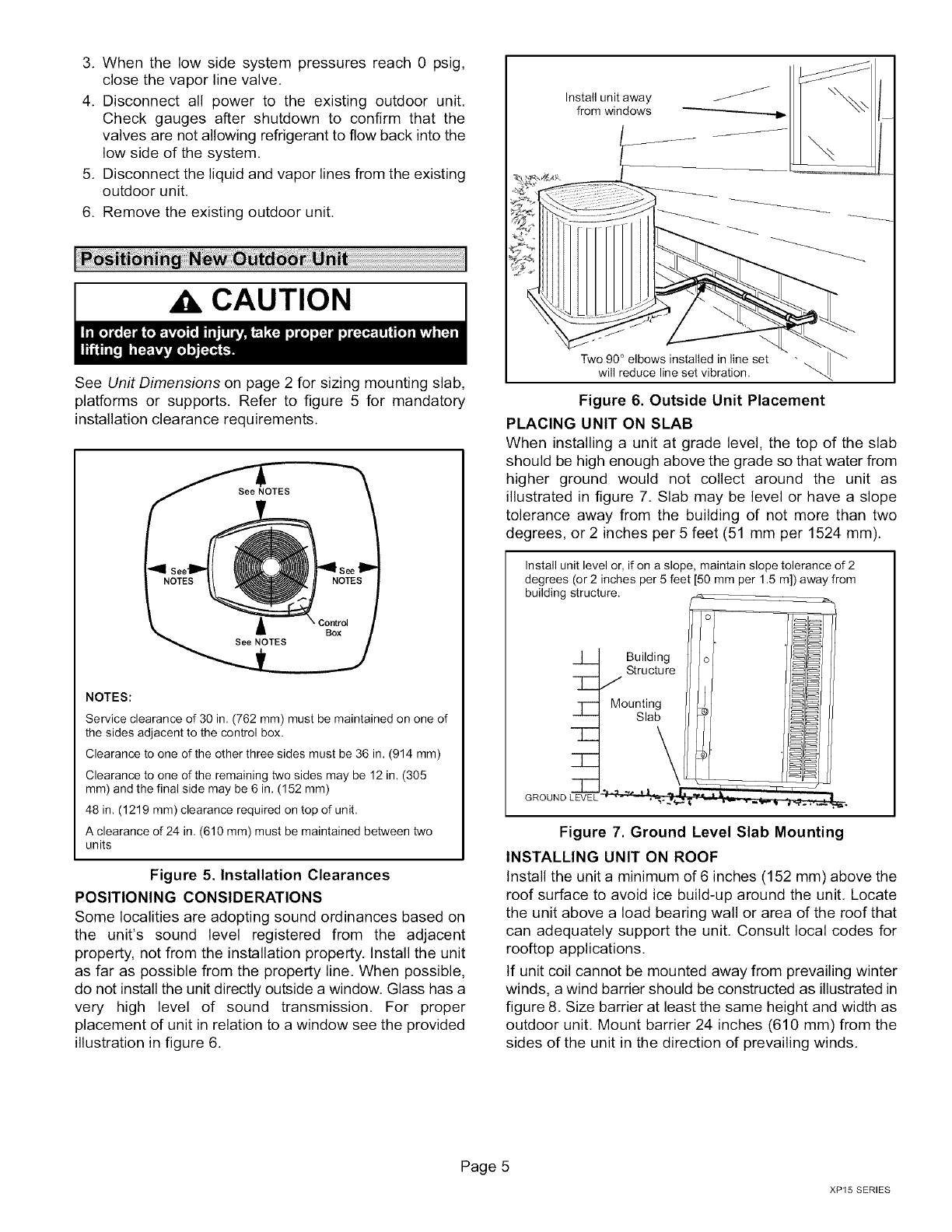
illustration in figure 6.
Install unit away
from windows
Two 90 ° elbows installed in line set -
will reduce line set vibration.
Figure 6. Outside Unit Placement
PLACING UNIT ON SLAB
When installing a unit at grade level, the top of the slab
should be high enough above the grade so that water from
higher ground would not collect around the unit as
illustrated in figure 7. Slab may be level or have a slope
tolerance away from the building of not more than two
degrees, or 2 inches per 5 feet (51 mm per 1524 mm).
Install unit level or, if on a slope, maintain slope tolerance of 2
degrees (or 2 inches per 5 feet [50 mm per 1.5 m]) away from
building structure.
Building
Structure
J
7/ Mounting
Slab
-T--
Figure 7. Ground Level Slab Mounting
INSTALLING UNIT ON ROOF
Install the unit a minimum of 6 inches (152 mm) above the
roof surface to avoid ice build-up around the unit. Locate
the unit above a load bearing wall or area of the roof that
can adequately support the unit, Consult local codes for
rooftop applications.
If unit coil cannot be mounted away from prevailing winter
winds, a wind barrier should be constructed as illustrated in
figure 8. Size barrier at least the same height and width as
outdoor unit, Mount barrier 24 inches (610 mm) from the
sides of the unit in the direction of prevailing winds.
Page 5
XP15 SERIES
PREVAILING _.
WINTER WINDS
I WIND BARRIER
INLET AIR ,_
INLETAIR
O INLET AIR
1
2_'_6" 10 ram)
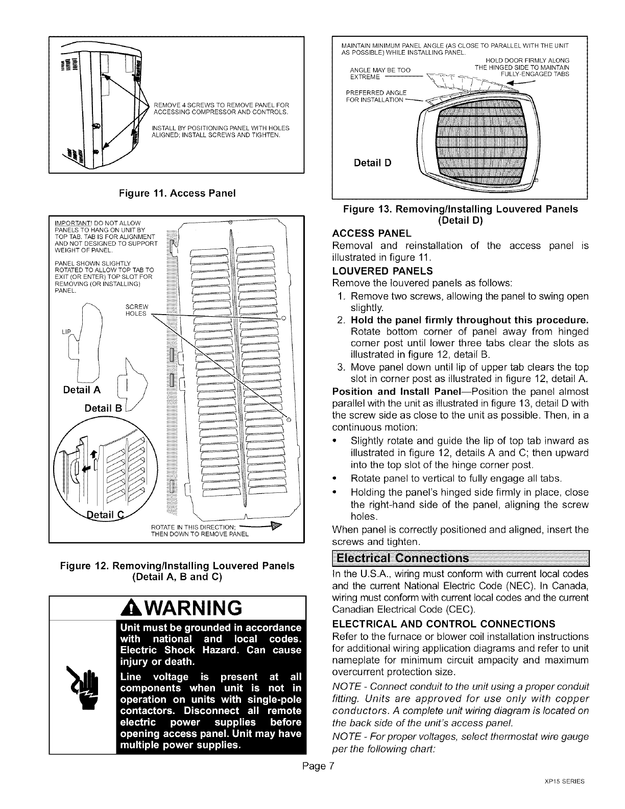
With unit positioned at installation site, remove two side
Iouvered panels to expose the unit base pan. Install the
brackets as illustrated in figure 10 using conventional
practices; replace the panels after installation is complete.
IMPORTANT
Figure 8. Rooftop Application and Wind Barrier
NOTE -If necessary for stability, anchor unit to slab as
described in Stabilizing Unit on Uneven Surfaces.
ELEVATING THE UNIT
These units are outfitted with elongated-shaped feet as
illustrated in figure 9.
BASE
LEG DETAIL 2"(50.8MM)
SCH 40
FEMALE
THREADED
ADAPTER
Figure 9. Elevated Slab Mounting using Feet
Extenders (Larger Base Units)
If additional elevation is necessary, raise the unit by
extending the height of the unit support feet. This may be
done with 2" SCH 40 female threaded adapter. The
specified coupling will fit snuggly into the recess portion of
the feet. Use additional 2" SCH 40 male threaded adapters
which can be threaded into the female threaded adapters
to make additional adjustments to the level of the unit.
NOTE -Keep the height of extenders short enough to
ensure a sturdy installation, If it is necessary to extend
further, consider a different type of field-fabricated
framework that is sturdy enough for greater heights.
STABILIZING UNIT ON UNEVEN SURFACES
To help stabilize an outdoor unit, some installations may
require strapping the unit to the pad using brackets and
anchors commonly available in the marketplace.
Page 6
Slab Side Mounting
#101/2" LONG
SELF-DRILLING SHEET
METAL SCREWS /
STABILIZING BRACKET
(18 GAUGE METAL - 2"
RW/DTDHi HEIGHT AS _,_1 f, _
#10 1-1/4" LONG HEX
HD SCREW AND
FLATWASHER
PLASTIC ANCHOR - USE IF CONCRETE
(HOLE DRILL 1/4"); NOT IF PLASTIC SLAB
(HOLE DRILL 1/8").
IDeck Top
Mounting
STABILIZING MINIMUM 1
BRACKET (18 PER SIDE
GAUGE METAL - 2"
WIDTH; HEIGHT
AS REQ'D); BEND
TO FORM RIGHT FOR EXTRA
ANGLE STABILITY
ONE BRACKET PER SIDE (MIN.); FOR EXTRA STABILITY,
TWO BRACKETS PER SIDE, 2" FROM EACH CORNER.
Figure 10. Installing Stabilizer Brackets
CAUTION
505328M 04/08
REMOVE4SCREWSTOREMOVEPANELFOR
ACCESSINGCOMPRESSORANDCONTROLS.
_ INSTALLBYPOSITIONINGPANELWITHHOLES
ALIGNED;INSTALLSCREWSANDTIGHTEN.
Figure 11. Access Panel
IMPORTANT! DO NOT ALLOW K-_
PANELS TO HANG ON UNIT BY
TOP TAB. TAB IS FOR ALIGNMENT )
ANDNOTDESIGNEDTOSUPPORT
WE,GHTOFPANEL
PANEL SHOWN SLIGHTLY _ _
ROTATED TO ALLOW TOP TAB TO _
EXIT (OR ENTER) TOP SLOT FOR _
REMOVING (OR INSTALLING) _
PANEL.
SCREW
L. HOLES......_ _iiii_///l _
U
ii t_
Detail A
Detail B -_-_\_
ROTATE IN THIS DIRECTION;
THEN DOWN TO REMOVE PANEL
MAINTAIN MINIMUM PANEL ANGLE (AS CLOSE TO PARALLEL WITH THE UNIT
AS POSSIBLE) WHILE INSTALLING PANEL.
HOLD DOOR FIRMLY ALONG
ANGLE MAY BE TOO THE HINGED SIDE TO MAINTAIN
EXTREME FULLY-ENGAGED TABS
PREFERRED ANGLE
FOR INSTALLATION
Detail D
Figure 13. Removing/Installing Louvered Panels
(Detail D)
ACCESS PANEL
Removal and reinstallation of the access panel is
illustrated in figure 11,
LOUVERED PANELS
Remove the Iouvered panels as follows:
1, Remove two screws, allowing the panel to swing open
slightly.
2, Hold the panel firmly throughout this procedure.
Rotate bottom corner of panel away from hinged
corner post until lower three tabs clear the slots as
illustrated in figure 12, detail B.
3, Move panel down until lip of upper tab clears the top
slot in corner post as illustrated in figure 12, detail A,
Position and Install Panel--Position the panel almost
parallel with the unit as illustrated in figure 13, detail D with
the screw side as close to the unit as possible. Then, in a
continuous motion:
• Slightly rotate and guide the lip of top tab inward as
illustrated in figure 12, details A and C; then upward
into the top slot of the hinge corner post.
• Rotate panel to vertical to fully engage all tabs,
• Holding the panel's hinged side firmly in place, close
the right-hand side of the panel, aligning the screw
holes.
When panel is correctly positioned and aligned, insert the
screws and tighten.
Figure 12. Removing/Installing Louvered Panels
(Detail A, B and C)
A'kWARNING
In the U,S.A., wiring must conform with current local codes
and the current National Electric Code (NEC). In Canada,
wiring must conform with current local codes and the current
Canadian Electrical Code (CEC),
ELECTRICAL AND CONTROL CONNECTIONS
Refer to the furnace or blower coil installation instructions
for additional wiring application diagrams and refer to unit
nameplate for minimum circuit ampacity and maximum
overcurrent protection size.
NOTE -Connect conduit to the unit using a proper conduit
fitting. Units are approved for use only with copper
conductors. A complete unit wiring diagram is located on
the back side of the unit's access panel.
NOTE -For proper voltages, select thermostat wire gauge
per the following chart:
Page 7
XP15 SERIES
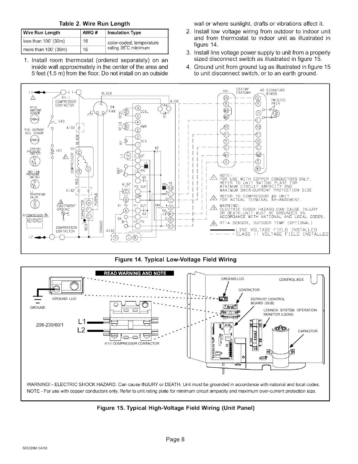
Table 2. Wire Run Length
Wire Run Length AWG # Insulation Type
less than 100' (30m) 18 color-coded, temperature
more than 100' (30m) 16 rating 35°C minimum
1. Install room thermostat (ordered separately) on an
inside wall approximately in the center of the area and
5 feet (1.5 m) from the floor. Do not install on an outside
wall or where sunlight, drafts or vibrations affect it.
2. Install low voltage wiring from outdoor to indoor unit
and from thermostat to indoor unit as illustrated in
figure 14.
3. Install line voltage power supply to unit from a properly
sized disconnect switch as illustrated in figure 15.
4. Ground unit from ground lug as illustrated in figure 15
to unit disconnect switch, or to an earth ground.
LI _._
z_
RTI$
AMBIENT
SENSOR
@
R721 DEFROST
COIL SENSOR
S4HIGH
PRESSURE
SWITCH
$87 LOW
PRESSURE
SWITCH
©
LI
REVERSING
VALVE
©
LZ_
OMPRESSOR
CONTACTOR
54O
AI32
BI
HRI
A
w
AI32
A
EQUIPMENT
GROUND
COMPRESSOR
CONTACTOR
BLACK TBI
(W5_
(W8
"-(v _
G
©
@
CB31MV
CBX32MV A2 SIGNATURE
81M2B
TWISTEO
PAIR
•I
A NOTE
FOR USE WITH COPPER CONDUCTORS ONLY.
REFER TO UNIT RATING PLATE FOR
MINIMUM CIRCUIT AMPACITY AND
MAXIMUM OVER CURRENT PROTECTION SIZE
A REFER TO COMPRESSOR N UNIT
FOR ACTUAL TERMINAL mRmANGEMENT.
Z_ WARNING
ELECTRIC SHOCK HAZARD,CAN CAUSE INJURY
OR DEATH.UNIT MUST BE GROUNDED IN
ACCOROANCE WITH NATIONAL AND LOCAL CODES.
A RTI4 SENSOR, OUTDOOR TEMP (OPTIONAL)
LINE VOLTAGE FIELD INSTALLED
CLASS II VOLTAGE FIELD INSTALLED
Figure 14. Typical Low-Voltage Field Wiring
GROUND
208-230/60/1 L1
L2
K1-1 COMPRESSOR CONTACTOR
GROUNDLUG CONTROLBOX _'-
CONTACTOR
DEFROST CONTROL
BOARD (DCB)
-''_/ L_)NNNTOoXRt LYs'<oTE_ OPERATION
"__ _[3_/ _ CAPACITOR
WARNING! - ELECTRIC SHOCK HAZARD. Can cause INJURY or DEATH. Unit must be grounded in accordance with national and local codes.
NOTE - For use with copper conductors only. Refer to unit rating plate for minimum circuit ampacity and maximum over-current protection size.
Figure 15. Typical High-Voltage Field Wiring (Unit Panel)
505328M 04/08
Page 8
This section providesinformationon installationor
replacementofexistinglinesets.Iflinesetsarenotbeing
installedorreplace,thenproceedtoBrazing Connections
on page 11.
If refrigerant lines are routed through a wall, seal and
isolate the opening so vibration is not transmitted to the
building, Pay close attention to line set isolation during
installation of any HVAC system. When properly isolated
from building structures (walls, ceilings, floors), the
refrigerant lines will not create unnecessary vibration and
subsequent sounds.
REFRIGERANT LINE SET
Field refrigerant piping consists of liquid and vapor lines
from the outdoor unit (sweat connections) to the indoor unit
coil (flare or sweat connections). Use Lennox L15 (sweat,
non41are) series line sets, or use field-fabricated
refrigerant lines as listed in table 3.
MATCHING WITH NEW OR EXISTING INDOOR COIL
AND LINE SET
IMPORTANT
When installing refrigerant lines longer than 50 feet, see
the Lennox Refrigerant Piping Design and Fabrication
Guidelines, or contact Lennox Technical Support Product
Applications for assistance. To obtain the correct
information from Lennox, be sure to communicate the
following points:
Model (XP15) and size (e.g. -060) of unit.
Line set diameters for the unit being installed (from
table 3)
Number of elbows and if there is a rise or drop of the
piping.
Line sets for heat pump applications can not be installed
underground. For more information see the Lennox
Refrigerant Piping Design and Fabrication Guidelines, or
contact Lennox Technical Support Product Applications
for assistance.
Table 3. Refrigerant Line Sets
Valve Sizes Recommended Line Set
Model Liquid Vapor Liquid Vapor L15
Line Line Line Line LineSets
-024 3/8 in. 3/4 in. 3/8 in 3/4 in. L15-41
-030 (10mm) (19mm) (10mm) (19mm) 15-50ft.
-- (5 - 15 m)
-036
-042 3/8 in. 7/8 in 3/8 in. 7/Sin L15-65
15 - 50 ft.
(10mm) (22mm) (10mm) (22mm) (5-15m)
3/8 in. 1-1/8 in, 3/8 in. 1-1/8 in, Field
-060 (10 ram) (29 ram) (10 ram) (29 ram) Fabricated
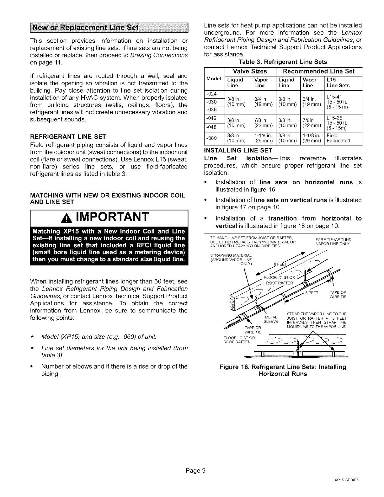
INSTALLING LINE SET
Line Set Isolation--This reference illustrates
procedures, which ensure proper refrigerant line set
isolation:
• Installation of line sets on horizontal runs is
illustrated in figure 16.
• Installation of line sets on vertical runs is illustrated
in figure 17 on page 10.
• Installation of a transition from horizontal to
vertical is illustrated in figure 18 on page 10.
TO HANG LINE SET FROM JOIST OR RAFTER,
USE EITHER METAL STRAPPING MATERIAL OR
ANCHORED HEAVY NYLON WIRE TIES.
WIRE TIE (AROUND
VAPOR LINE ONLY
STRAPPING MATERIAL
(AROUND VAPOR LINE
ONLY)
8 FEET TAPE OR
WIRE TIE
STRAP THE VAPOR LINE TO THE
METAL JOIST OR RAFTER AT 8 FEET
SLEEVE INTERVALS THEN STRAP THE
TAPE OR LIQUID LINE TO THE VAPOR LINE.
FLOOR JOIST OR _ _ _%
ROOF RAFTER _-
_._ I1
Figure 16. Refrigerant Line Sets: Installing
Horizontal Runs
Page 9
XP15 SERIES
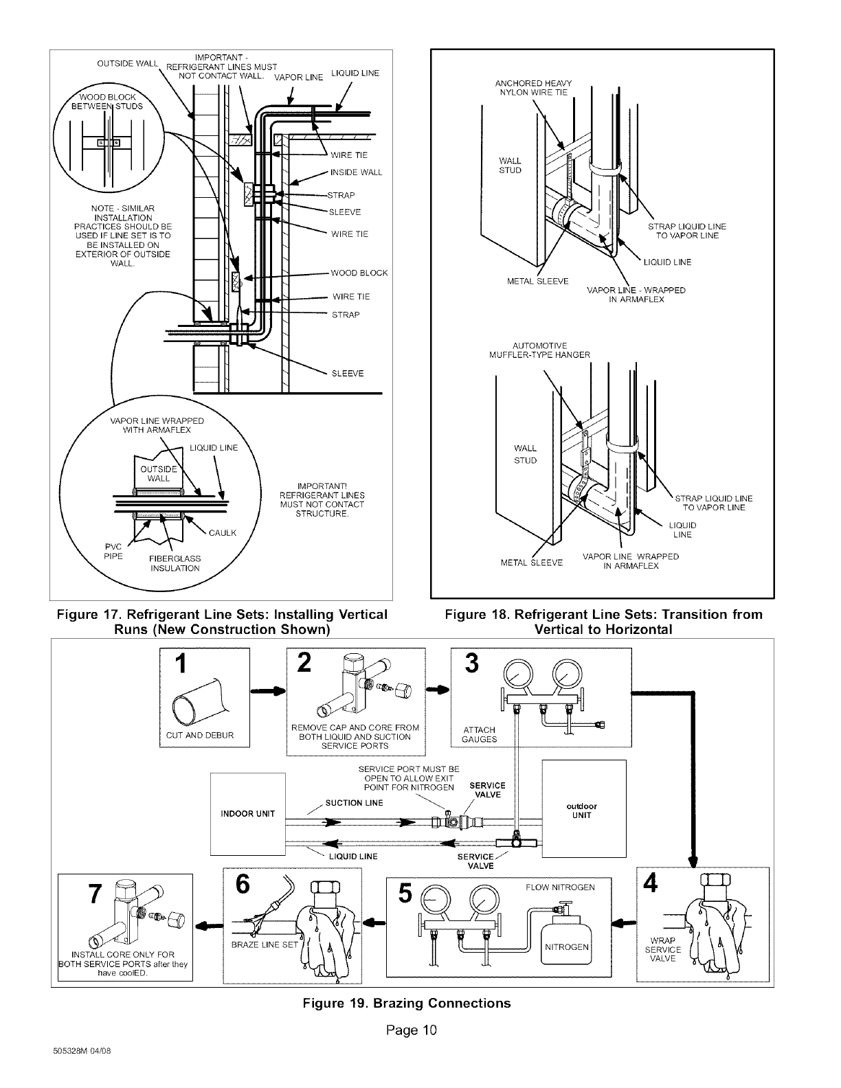
IMPORTANT-
OUTSIDEWALLREFRIGERANTLINESMUST
NOTCONTACTWALL.VAPORLINELIQUIDLINE
NOTE-SIMILAR
INSTALLATION
PRACTICESSHOULDBE
USEDIFLINESETISTO
BEINSTALLEDON
EXTERIOROFOUTSIDE
WALL.
VAPORLINEWRAPPED
WITHARMAFLEX
PVC_ CAULK
PIPE FIBERGLASS
INSULATION
IMPORTANT!
REFRIGERANTLINES
MUSTNOTCONTACT
STRUCTURE.
ANCHOREDHEAVY
NYLONWIRETIE
WALL
STUD
METALSLEEVE
AUTOMOTIVE
MUFFLER-TYPEHANGER
WALL
STUD
STRAPLIQUIDLINE
TOVAPORLINE
JIDLINE
VAPORLINE-WRAPPED
INARMAFLEX
IUIDLINE
TOVAPORLINE
LIQUID
LINE
VAPORLINEWRAPPED
METALSLEEVE INARMAFLEX
Figure 17. Refrigerant Line Sets: Installing Vertical
Runs (New Construction Shown) Figure 18. Refrigerant Line Sets: Transition from
Vertical to Horizontal
1
CUT AND DEBUR
INSTALL CORE ONLY FOR
3OTH SERVICE PORTS after they
have coolED.
INDOOR UNIT
REMOVE CAP AND CORE FROM
BOTH LIQUID AND SUCTION
SERVICE PORTS
outdoor
UNIT
SERVICE PORT MUST BE
OPEN TO ALLOW EXIT
POINT FOR NITROGEN SERVICE
j SUCTION LINE _/VALVE
_QU_DUNE SERV_CEJ
VALVE
Figure 19. Brazing Connections
Page 10
505328M 04/08
ISOLATION GROMMETS
Locate the provided isolation grommets Slide grommets
onto vapor and liquid lines Insert grommets into mullion to
isolate refrigerant lines from sheet metal edges
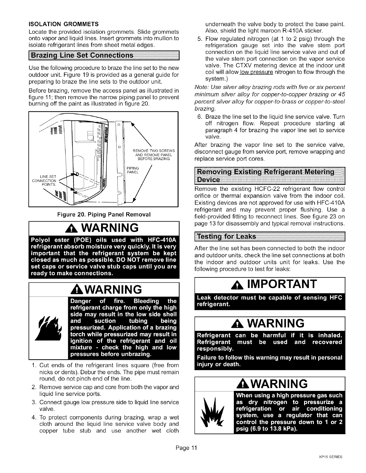
Use the following procedure to braze the line set to the new
outdoor unit Figure 19 is provided as a general guide for
preparing to braze the line sets to the outdoor unit
Before brazing, remove the access panel as illustrated in
figure 11; then remove the narrow piping panel to prevent
burning off the paint as illustrated in figure 20
REMOVE TWO SCREWS
AND REMOVE PANEL
BEFORE BRAZING
LINE SET
CONNECTION
POINTS
Figure 20. Piping Panel Removal
WARNING
_WARNING
underneath the valve body to protect the base paint,
Also, shield the light maroon R-410A sticker.
5. Flow regulated nitrogen (at 1 to 2 psig) through the
refrigeration gauge set into the valve stem port
connection on the liquid line service valve and out of
the valve stem port connection on the vapor service
valve. The CTXV metering device at the indoor unit
coil will allow low pressure nitrogen to flow through the
system,)
Note: Use silver alloy brazing rods with five or six percent
minimum silver alloy for copper-to-copper brazing or 45
percent silver alloy for copper-to-brass or copper-to-steel
brazing,
6. Braze the line set to the liquid line service valve. Turn
off nitrogen flow, Repeat procedure starting at
paragraph 4 for brazing the vapor line set to service
valve,
After brazing the vapor line set to the service valve,
disconnect gauge from service port, remove wrapping and
replace service port cores.
Remove the existing HCFC-22 refrigerant flow control
orifice or thermal expansion valve from the indoor coil.
Existing devices are not approved for use with HFC-410A
refrigerant and may prevent proper flushing. Use a
field-provided fitting to reconnect lines, See figure 23 on
page 13 for disassembly and typical removal instructions.
After the line set has been connected to both the indoor
and outdoor units, check the line set connections at both
the indoor and outdoor units unit for leaks. Use the
following procedure to test for leaks:
IMPORTANT
WARNING
1. Cut ends of the refrigerant lines square (free from
nicks or dents). Debur the ends. The pipe must remain
round, do not pinch end of the line.
2. Remove service cap and core from both the vapor and
liquid line service ports.
3. Connect gauge low pressure side to liquid line service
valve,
4. To protect components during brazing, wrap a wet
cloth around the liquid line service valve body and
copper tube stub and use another wet cloth
Page 11
AWARNING
XP15 SERIES
WARNING I OUTOOORO.,T
SERVICE VALVE
1 Connect an HFC410A manifold gauge set high
pressure hose to the vapor valve service port
(Normally the high pressure hose is connected to the
liquid line port; however, connecting it to the vapor port
better protects the manifold gauge set from high
pressure damage.)
2 With both manifold valves closed connect the cylinder
of HFC410A refrigerant to the center port of the
manifold gauge set Open the valve on the HFC 410A
cylinder (vapor only)
3 Open the high pressure side of the manifold to allow
HFC 410A into the line set and indoor unit
4 Weigh in a trace amount of HFC410A [,4 trace
amount is a maximum of two ounces (57 g) refrigerant
or three pounds (31 kPa) pressure].
5, Close the valve on the HFC-410A cylinder and the
valve on the high pressure side of the manifold gauge
set.
6. Disconnect the HFC-410A cylinder,
7, Connect a cylinder of dry nitrogen with a pressure
regulating valve to the center port of the manifold
gauge set,
8, Adjust dry nitrogen pressure to 150 psig (1034 kPa),
9, Open the valve on the high side of the manifold gauge
set in order to pressurize the line set and the indoor unit,
10, After a few minutes, open one of the service valve
ports and verify that the refrigerant added to the
system earlier is measurable with a leak detector,
11, After leak testing disconnect gauges from service
ports,
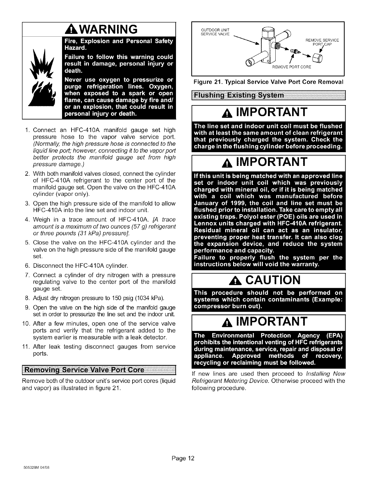
REMOVE SERVICE
PORT CAP
REMOVE PORT CORE
Figure 21. Typical Service Valve Port Core Removal
AIMPORTANT
A IMPORTANT
ACAUTION
AIMPORTANT
Remove both of the outdoor unit's service port cores (liquid
and vapor) as illustrated in figure 21,
If new lines are used then proceed to Installing New
Refrigerant Metering Device. Otherwise proceed with the
following procedure,
505328M 04/08
Page 12
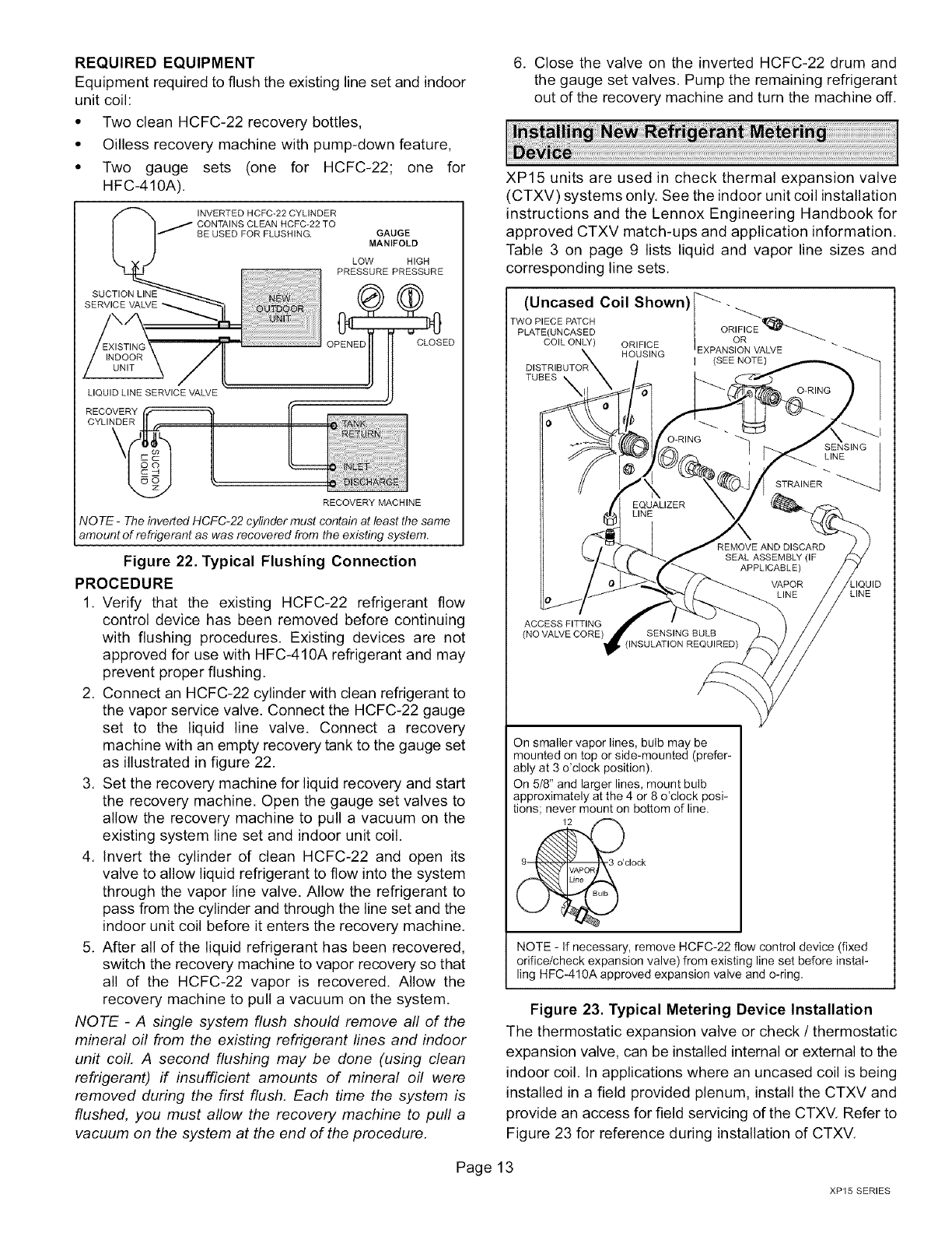
REQUIRED EQUIPMENT
Equipment required to flush the existing line set and indoor
unit coil:
• Two clean HCFC-22 recovery bottles,
• Oilless recovery machine with pump-down feature,
• Two gauge sets (one for HCFC-22; one for
HFC-410A),
RECOVERY MACHINE
NOTE -The inverted HCFC-22 cylinder must contain at least the same
amount of refrigerant as was recovered from the existing system.
Figure 22. Typical Flushing Connection
PROCEDURE
1, Verify that the existing HCFC-22 refrigerant flow
control device has been removed before continuing
with flushing procedures. Existing devices are not
approved for use with HFC-410A refrigerant and may
prevent proper flushing.
2, Connect an HCFC-22 cylinder with clean refrigerant to
the vapor service valve. Connect the HCFC-22 gauge
set to the liquid line valve. Connect a recovery
machine with an empty recovery tank to the gauge set
as illustrated in figure 22.
3, Set the recovery machine for liquid recovery and start
the recovery machine. Open the gauge set valves to
allow the recovery machine to pull a vacuum on the
existing system line set and indoor unit coil.
4, Invert the cylinder of clean HCFC-22 and open its
valve to allow liquid refrigerant to flow into the system
through the vapor line valve. Allow the refrigerant to
pass from the cylinder and through the line set and the
indoor unit coil before it enters the recovery machine,
5, After all of the liquid refrigerant has been recovered,
switch the recovery machine to vapor recovery so that
all of the HCFC-22 vapor is recovered. Allow the
recovery machine to pull a vacuum on the system,
NOTE -A single system flush should remove all of the
mineral oil from the existing refrigerant lines and indoor
unit coil. A second flushing may be done (using clean
refrigerant) if insufficient amounts of mineral oil were
removed during the first flush. Each time the system is
flushed, you must allow the recovery machine to pull a
vacuum on the system at the end of the procedure.
Page1
6, Close the valve on the inverted HCFC-22 drum and
the gauge set valves. Pump the remaining refrigerant
out of the recovery machine and turn the machine off.
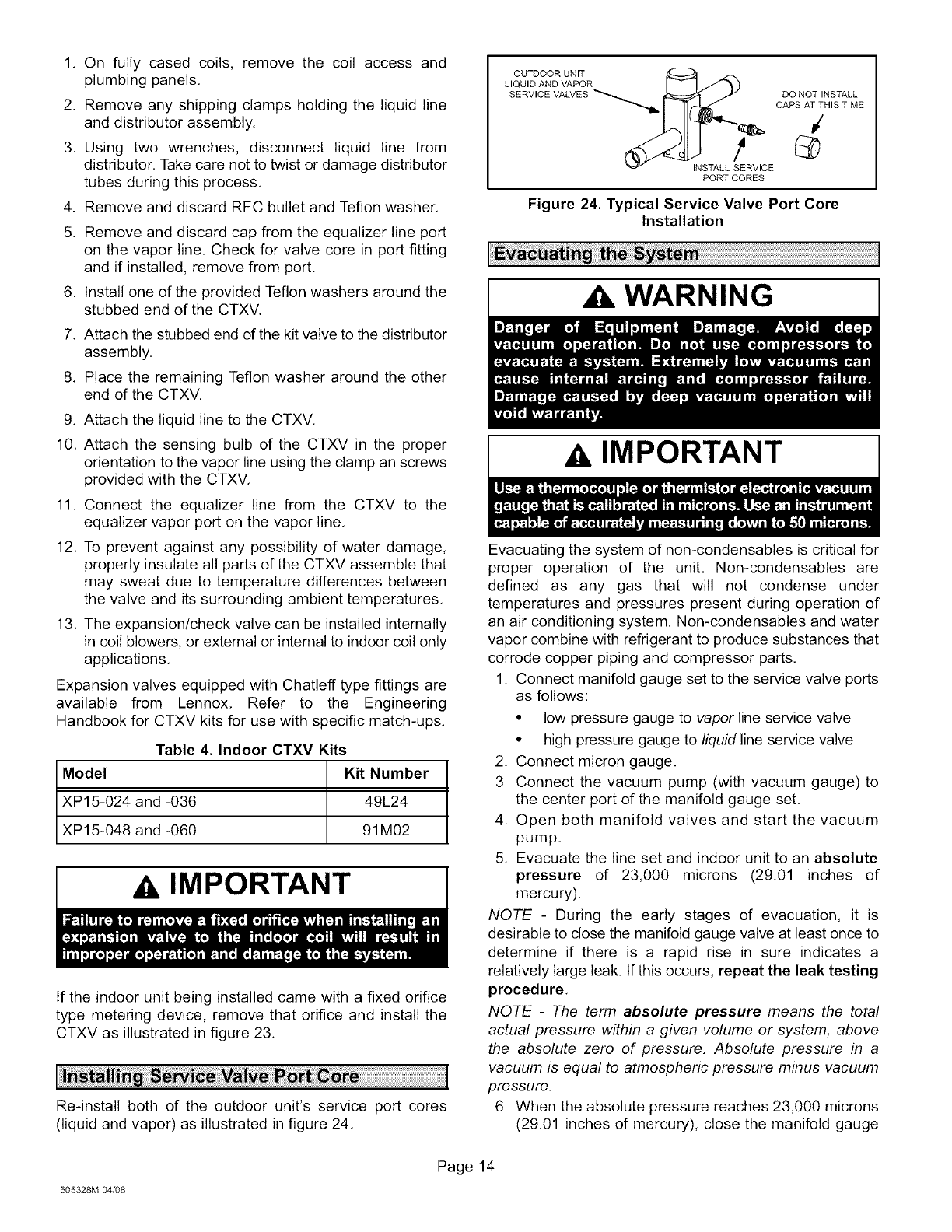
XP15 units are used in check thermal expansion valve
(CTXV) systems only, See the indoor unit coil installation
instructions and the Lennox Engineering Handbook for
approved CTXV match-ups and application information.
Table 3 on page 9 lists liquid and vapor line sizes and
corresponding line sets,
(Uncased Coil Shown)_ -
TWO PIECE PATCH
I EXPA )RI FIC E _""_
PLATE(UNCASED OR
COIL ONLY) ORIFICE NSION VALVE
HOUSING I (SEE NOTE)
TUBES
ACCESS FITTING
(NO VALVE CORE)
On smaller vapor lines, bulb may be
mounted on top or side-mounted (prefer-
ably at 3 o'clock position).
On 518"and larger lines, mount bulb
approximately at the 4 or 8 o'clock posi-
tions; never mount on bottom of line.
o@clock
NOTE - If necessary, remove HCFC-22 flow control device (fixed
orifice/check expansion valve) from existing line set before instal-
ling HFC-410A approved expansion valve and o-ring.
Figure 23. Typical Metering Device Installation
The thermostatic expansion valve or check /thermostatic
expansion valve, can be installed internal or external to the
indoor coil. In applications where an uncased coil is being
installed in a field provided plenum, install the CTXV and
provide an access for field servicing of the CTXV. Refer to
Figure 23 for reference during installation of CTXV,
XP15 SERIES
1, On fully cased coils, remove the coil access and
plumbing panels,
2, Remove any shipping clamps holding the liquid line
and distributor assembly,
3. Using two wrenches, disconnect liquid line from
distributor. Take care not to twist or damage distributor
tubes during this process,
4, Remove and discard RFC bullet and Teflon washer,
5. Remove and discard cap from the equalizer line port
on the vapor line. Check for valve core in port fitting
and if installed, remove from port.
6. Install one of the provided Teflon washers around the
stubbed end of the CTXV,
7. Attach the stubbed end of the kit valve to the distributor
assembly.
8. Place the remaining Teflon washer around the other
end of the CTXV.
9. Attach the liquid line to the CTXV.
10. Attach the sensing bulb of the CTXV in the proper
orientation to the vapor line using the clamp an screws
provided with the CTXV,
11. Connect the equalizer line from the CTXV to the
equalizer vapor port on the vapor line.
12. To prevent against any possibility of water damage,
properly insulate all parts of the CTXV assemble that
may sweat due to temperature differences between
the valve and its surrounding ambient temperatures.
13. The expansion/check valve can be installed internally
in coil blowers, or external or internal to indoor coil only
applications,
Expansion valves equipped with Chatleff type fittings are
available from Lennox, Refer to the Engineering
Handbook for CTXV kits for use with specific match-ups.
Table 4. Indoor CTXV Kits
Model Kit Number
XP15-024 and -036 49L24
XP15-048 and -060 91M02
AIMPORTANT
If the indoor unit being installed came with a fixed orifice
type metering device, remove that orifice and install the
CTXV as illustrated in figure 23.
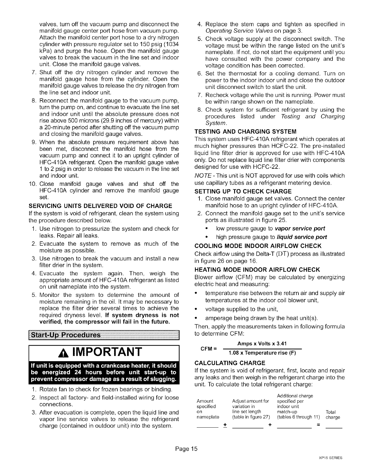
Re-install both of the outdoor unit's service port cores
(liquid and vapor) as illustrated in figure 24.
O TOOO .
LIQUID AND VAPOR
SERVICE VALVES DO NOT INSTALL
CAPS AT THIS TIME
INSTALL SERVICE
PORT CORES
Figure 24. Typical Service Valve Port Core
Installation
WARNING
AIMPORTANT
Evacuating the system of non-condensables is critical for
proper operation of the unit. Non-condensables are
defined as any gas that will not condense under
temperatures and pressures present during operation of
an air conditioning system. Non-condensables and water
vapor combine with refrigerant to produce substances that
corrode copper piping and compressor parts.
1. Connect manifold gauge set to the service valve ports
as follows:
• low pressure gauge to vapor line service valve
• high pressure gauge to liquid line service valve
2. Connect micron gauge.
3. Connect the vacuum pump (with vacuum gauge) to
the center port of the manifold gauge set,
4. Open both manifold valves and start the vacuum
pump.
5. Evacuate the line set and indoor unit to an absolute
pressure of 23,000 microns (29.01 inches of
mercury).
NOTE - During the early stages of evacuation, it is
desirable to close the manifold gauge valve at least once to
determine if there is a rapid rise in sure indicates a
relatively large leak, If this occurs, repeat the leak testing
procedure.
NOTE -The term absolute pressure means the total
actual pressure within a given volume or system, above
the absolute zero of pressure. Absolute pressure in a
vacuum is equal to atmospheric pressure minus vacuum
pressure,
6. When the absolute pressure reaches 23,000 microns
(29.01 inches of mercury), close the manifold gauge
505328M 04_8
Page 14
valves,turnoffthevacuumpumpanddisconnectthe
manifoldgaugecenterporthosefromvacuumpump.
Attachthemanifoldcenterporthosetoadrynitrogen
cylinderwithpressureregulatorsetto 150psig(1034
kPa)andpurgethehose.Openthemanifoldgauge
valvestobreakthevacuuminthelinesetandindoor
unit.Closethemanifoldgaugevalves,
7, Shutoff the dry nitrogencylinderand removethe
manifoldgaugehosefromthe cylinder.Openthe
manifoldgaugevalvestoreleasethedrynitrogenfrom
thelinesetandindoorunit,
8, Reconnectthemanifoldgaugeto thevacuumpump,
turnthepumpon,andcontinuetoevacuatethelineset
andindoorunituntiltheabsolutepressuredoesnot
riseabove500microns(29.9inchesofmercury)within
a 20-minuteperiodaftershuttingoffthevacuumpump
andclosingthemanifoldgaugevalves.
9, Whentheabsolutepressurerequirementabovehas
beenmet,disconnectthe manifoldhosefrom the
vacuumpumpandconnectit to anuprightcylinderof
HFC-410Arefrigerant,Openthemanifoldgaugevalve
1to2 psiginordertoreleasethevacuuminthelineset
andindoorunit,
10,Close manifoldgauge valvesand shut off the
HFC-410Acylinderandremovethe manifoldgauge
set,
SERVICINGUNITSDELIVEREDVOIDOFCHARGE
Ifthesystemisvoidofrefrigerant,cleanthesystemusing
theproceduredescribedbelow,
1, Usenitrogentopressurizethesystemandcheckfor
leaks,Repairallleaks,
2, Evacuatethe systemto removeas muchof the
moistureaspossible,
3, Usenitrogento breakthevacuumandinstalla new
filterdrierinthesystem.
4, Evacuatethe system again. Then, weigh the
appropriateamountof HFC-410Arefrigerantaslisted
onunitnameplateintothesystem.
5, Monitorthe systemto determinethe amountof
moistureremainingintheoil.Itmaybenecessaryto
replacethefilterdrierseveraltimesto achievethe
requireddrynesslevel.If systemdryness is not
verified,thecompressorwill fail in thefuture.
IMPORTANT
1. Rotate fan to check for frozen bearings or binding.
2, Inspect all factory- and field-installed wiring for loose
connections.
3, After evacuation is complete, open the liquid line and
vapor line service valves to release the refrigerant
charge (contained in outdoor unit) into the system,
4, Replace the stem caps and tighten as specified in
Operating Service Valves on page 3.
5, Check voltage supply at the disconnect switch. The
voltage must be within the range listed on the unit's
nameplate. If not, do not start the equipment until you
have consulted with the power company and the
voltage condition has been corrected,
6, Set the thermostat for a cooling demand. Turn on
power to the indoor indoor unit and close the outdoor
unit disconnect switch to start the unit.
7, Recheck voltage while the unit is running. Power must
be within range shown on the nameplate,
8, Check system for sufficient refrigerant by using the
procedures listed under Testing and Charging
System,
TESTING AND CHARGING SYSTEM
This system uses HFC-410A refrigerant which operates at
much higher pressures than HCFC-22. The pre-installed
liquid line filter drier is approved for use with HFC-410A
only, Do not replace liquid line filter drier with components
designed for use with HCFC-22,
NOTE - This unit is NOT approved for use with coils which
use capillary tubes as a refrigerant metering device,
SETTING UP TO CHECK CHARGE
1. Close manifold gauge set valves. Connect the center
manifold hose to an upright cylinder of HFC-410A.
2. Connect the manifold gauge set to the unit's service
ports as illustrated in figure 25,
•low pressure gauge to vapor service port
• high pressure gauge to liquid service port
COOLING MODE INDOOR AIRFLOW CHECK
Check airflow using the Delta-T (DT) process as illustrated
in figure 26 on page 16.
HEATING MODE INDOOR AIRFLOW CHECK
Blower airflow (CFM) may be calculated by energizing
electric heat and measuring:
• temperature rise between the return air and supply air
temperatures at the indoor coil blower unit,
• voltage supplied to the unit,
• amperage being drawn by the heat unit(s),
Then, apply the measurements taken in following formula
to determine CFM:
CFM = Amps x Volts x 3.41
1.08 x Temperature rise (F)
CALCULATING CHARGE
If the system is void of refrigerant, first, locate and repair
any leaks and then weigh in the refrigerant charge into the
unit, To calculate the total refrigerant charge:
Additional charge
Amount Adjust amount for specified per
specified variation in indoor unit
on line set length match-up Total
nameplate (table in figure 27) (tables 6 through 11) charge
+ + =
Page15
XP15 SERIES
CHECK
EXPANSIONVALVE
LOW HIGH [
PRESSUREPRESSURE
_:[tGAUGEMANIFO%D1]:_
HFC-410 LINEI
ADRUM VALVE COMPRESSOF
J2
DISTRIBUTOR
DRIER OUTDOOR
CO,L
MUFFLER
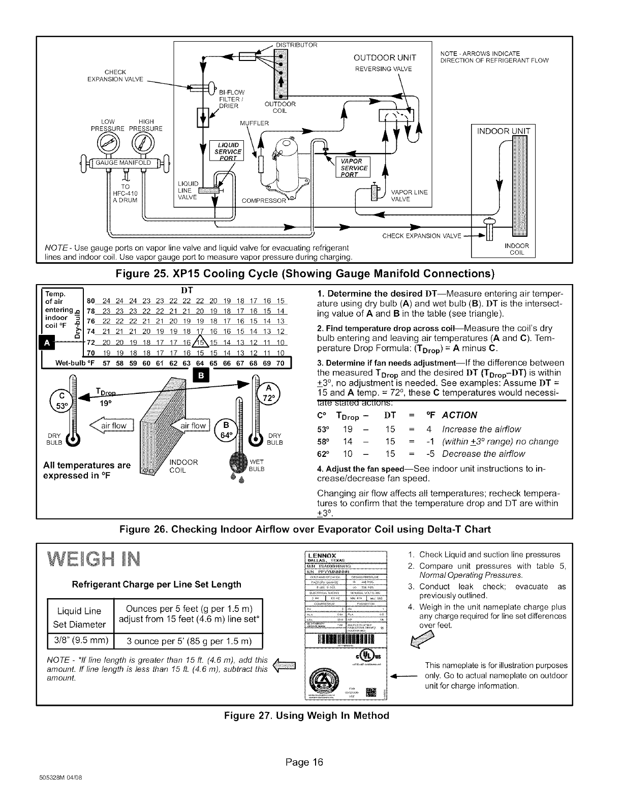
NOTE- Use gauge ports on vapor line valve and liquid valve for evacuating refrigerant
lines and indoor coil. Use vapor gauge port to measure vapor pressure during charging,
OUTDOOR UNIT
REVERSING VALVE
VAPOR LINE
VALVE
CHECK EXPANSION VALVE --
NOTE -ARROWS INDICATE
DIRECTION OF REFRIGERANT FLOW
INDOOR UNIT
INDOOR
COIL
Figure 25. XP15 Cooling Cycle (Showing Gauge Manifold Connections)
Temp. l
of air I 80 24
I
entering,_ I 78 23
indoor _ I== 22
coil °F _'?1tu
"- 17421
I
72 20
70 19
Wet-bulb °F 57
DT
24 24 23 23 22 22 22 20 19 18 17 16 15
23 23 22 22 21 21 20 19 18 17 16 15 14
22 22 21 21 20 19 19 18 17 16 15 14 13
21 21 20 19 19 18 17 16 16 15 14 13 12
20 19 18 17 17 161L55_15 14 13 12 11 10
19 18 18 17 17 16 15 15 14 13 12 11 10
58 59 60 61 62 63 64 65 66 67 68 69 70 I
n$
19°
iNDOOR WET
All temperatures are COiL BULB
expressed in °F 6
DRY
BULB
1. Determine the desired DT--Measure entering air temper-
ature using dry bulb (A) and wet bulb (B). DT is the intersect-
ing value of A and B in the table (see triangle).
2. Find temperature drop across coil--Measure the coil's dry
bulb entering and leaving air temperatures (A and C). Tem-
perature Drop Formula: (TDrop) = A minus C.
3. Determine if fan needs adjustment--If the difference between
the measured TDrop and the desired DT (TDrop-DT) is within
+_3°, no adjustment is needed. See examples: Assume DT =
15 and A temp. = 72 °, these C temperatures would necessi-
LEILI9 _LaL_d EI(3LIUII_:
C°TDrop- DT =°F ACTION
53°19 - 15 = 4 Increase the airflow
58°14 - 15 = -1 (within +3° range) no change
62 °10 - 15 = -5 Decrease the airflow
4. Adjust the fan speed--See indoor unit instructions to in-
crease/decrease fan speed.
Changing air flow affects all temperatures; recheck tempera-
tures to confirm that the temperature drop and DT are within
+_30.
Figure 26. Checking Indoor Airflow over Evaporator Coil using Delta-T Chart
WEIGH
Refrigerant Charge per Line Set Length
Liquid Line Ounces per 5 feet (g per 1.5 m)
Set Diameter adjust from 15 feet (4.6 m) line set*
3t8" (9.5 mm) 3 ounce per 5' (85 g per 1.5 m)
NOTE - *If line length is greater than 15 ft. (4.6 m), add this
amount. If line length is less than 15 ft. (4.6 m), subtract this
amount.
L_NNOX
HIHIIIJI|I[I
@:L,
1. Check Liquid and suction line pressures
2. Compare unit pressures with table 5,
Normal Operating Pressures,
3. Conduct leak check; evacuate as
previously outlined.
4. Weigh in the unit nameplate charge plus
any charge required for line set differences
over feet,
This nameplate is for illustration purposes
only. Go to actual nameplate on outdoor
unit for charge information.
Figure 27. Using Weigh In Method
505328M 04/08
Page 16
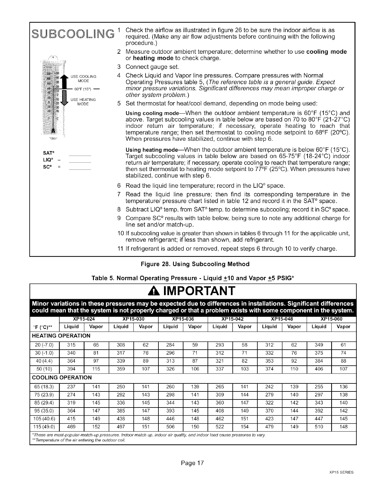
8UBCOOLING 1
USE COOLING
MODE
60°F (15 °) --
USE HEATING
MODE
2
3
4
%
SATo
LIQ o -
SC o =
Check the airflow as illustrated in figure 26 to be sure the indoor airflow is as
required. (Make any air flow adjustments before continuing with the following
procedure.)
Measure outdoor ambient temperature; determine whether to use cooling mode
or heating mode to check charge.
Connect gauge set.
Check Liquid and Vapor line pressures. Compare pressures with Normal
Operating Pressures table 5, (The reference table is a general guide. Expect
minor pressure variations. Significant differences may mean improper charge or
other system problem. )
Set thermostat for heat/cool demand, depending on mode being used:
Using cooling mode--When the outdoor ambient temperature is 60°F (15°C) and
above. Target subcooling values in table below are based on 70 to 80°F (21-27°C)
indoor return air temperature; if necessary, operate heating to reach that
temperature range; then set thermostat to cooling mode setpoint to 68°F (20°C).
When pressures have stabilized, continue with step 6.
Using heating mode--When the outdoor ambient temperature is below 60°F (15°C).
Target subcooling values in table below are based on 65-75°F (18-24°C) indoor
return air temperature; if necessary, operate cooling to reach that temperature range;
then set thermostat to heating mode setpoint to 77°F (25°C). When pressures have
stabilized, continue with step 6.
6 Read the liquid line temperature; record in the LIQ ° space.
7 Read the liquid line pressure; then find its corresponding temperature in the
temperature/pressure chart listed in table 12 and record it in the SAT° space.
8 Subtract LIQ° temp. from SAT° temp. to determine subcooling; record it in SC° space.
9 Compare SC° results with table below, being sure to note any additional charge for
line set and/or match-up.
10 If subcooling value is greater than shown in tables 6 through 11 for the applicable unit,
remove refrigerant; if less than shown, add refrigerant.
11 If refrigerant is added or removed, repeat steps 6 through 10 to verify charge.
Figure 28. Using Subcooling Method
Table 5. Normal Operating Pressure - Liquid +10 and Vapor +5 PSIG*
IMPORTANT
|lliiliTo]ilv/_-I IP.|l[[o]i[-.lllilllii['4-"[_]l)i] I[:t-$"]!ll':-.t-lliiL.]Iv|i[_ :--,).-4i[:[_rlrl_irilrlll_l_-41[-4i[_-4.111i!11i1,¢ _-"ll .F'[|[o]i[..'!ll_-'l[i-']'_ilil i,_.]i|l[ill_l[q 1['4i[_:t-11
""""'"" il"""T II
XP15-024 XP15-030 XP15-036 XP15-042 XP15-048 XP15-060
..aidIvo o. Ivo o. Ivo o...aidIVo o. IVo o. IVo o.
HEATINGOPERATION
20 (-7.0) 315 65 308 62 284 59 293 58 312 62 349 61
30 (-1.0) 340 81 317 76 296 71 312 71 332 76 375 74
40 (4.4) 364 97 339 89 313 87 321 82 353 92 384 88
50 (10) 394 115 359 107 326 106 337 103 374 110 406 107
COOLING OPERATION
65 (18.3) 237 141 250 141 260 139 265 141 242 139 255 136
75 (23.9) 274 143 292 143 298 141 309 144 279 140 297 138
85 (29.4) 319 145 336 145 344 143 360 147 322 142 343 140
95 (35.0) 364 147 385 147 393 145 408 149 370 144 392 142
105 (40.6) 415 149 438 148 446 148 462 151 423 147 447 145
115 (49.0) 469 152 497 151 506 150 522 154 479 149 510 148
*These are most-popular-match-up pressure& Indoor match up, indoor air quality, and indoor load cause pressures to vary.
**Temperature of the air entering the outdoor coi!.
Page 17
XP15 SERIES
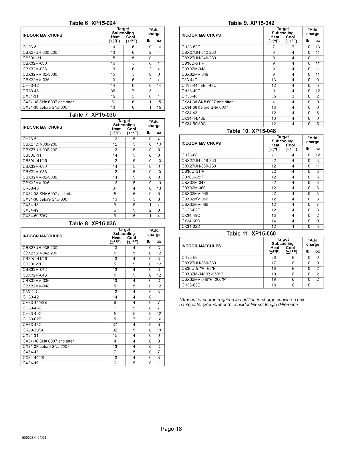
Table 6. XP15-024
Target *Add
Subcooling charge
INDOOR MATCHUPS Heat Cool
(+5OF) (+1OF) Ib oz
CH23-51 14 6 0 14
CBX27UH-030-230 13 6 2 4
CB3OU-31 15 5 O 1
CBX32M-030 15 5 O 1
CBX32M-036 13 6 2 4
CBX32MV-024/030 15 5 O O
CBX32MV-036 13 6 2 4
CH33-42 14 6 O 14
CR33-48 38 7 3 1
CX34-31 15 5 0 1
CX34-38 SN# 6007 and after 6 6 1 15
CX34-38 before SN# 6007 13 6 1 15
Table 7. XP15-030
Target *Add
Subcooling charge
INDOOR MATCHUPS Heat Cool
(+5OF) (+1OF) Ib oz
CH23-51 13 5 0 4
CBX27UH-030-230 12 5 0 10
CBX27UH-036-230 13 5 0 8
CB30U-31 14 5 0 0
CB30U-41/46 12 5 0 10
CBX32M-030 14 5 0 0
CBX32M-036 12 5 0 10
CBX32MV-024/030 14 5 0 0
CBX32MV-036 12 5 0 10
CR33-48 31 4 0 13
CX34-38 SN# 6007 and after 5 5 0 8
CX34-38 before SN# 6007 13 5 0 8
CX34-43 9 5 1 4
CX34-49 6 5 2 0
CX34-50/60C 9 5 1 4
Table 8. XP15-036
Target *Add
Subcooling charge
INDOOR MATCHUPS Heat Cool
(+5OF) (+1OF) Ib oz
CBX27UH-036-230 13 4 0 3
CBX27UH-042-230 5 5 O 12
CB3OU-41/46 13 4 O 3
CB3OU-51 5 5 O 12
CBX32M-042 13 4 O 3
CBX32M-048 5 5 O 12
CBX32MV-036 13 4 O 3
CBX32MV-048 5 5 O 12
C33-44C 13 4 O 3
CH33-42 14 4 O 1
CH33-44/48B 9 4 O 7
CH33-48C 7 5 O 7
CH33-49C 5 5 O 12
CH33-62D 5 7 O 14
CR33-48C 37 4 O 5
CR33-50/60 32 5 O 10
CX34-31 15 4 O O
CX34-38 SN# 6007 and after 4 4 O 3
CX34-38 before SN# 6007 13 4 O 3
CX34-43 7 5 O 7
CX34-44/48 13 4 O 3
CX34-49 6 5 O 11
Table 9. XP15-042
Target *Add
Subcooling charge
INDOOR MATCHUPS Heat Cool
(+5OF) (+1OF) Ib oz
CH33-62D 7 7 0 13
CBX27UH-042-230 9 4 O 11
CBX27UH-048-230 9 4 O 11
CB3OU-51*P 9 4 O 11
CBX32M-048 9 4 O 11
CBX32MV-048 9 4 O 11
C33-44C 13 4 O O
CH33-44/48B, -48C 12 4 O 5
CH33-49C 9 4 O 12
CR33-48 35 3 O 2
CX34-38 SN# 6007 and after 4 4 O O
CX34-38 before SN# 6007 13 4 O O
CX34-43 12 4 O 5
CX34-44/48B 13 4 O O
CX34-50/60C 12 4 O 5
Table 10. XP1 _-048
Target *Add
Subcooling charge
INDOOR MATCHUPS Heat Cool
(+5OF) (+1OF) Ib oz
CH23-68 21 4 0 12
CBX27UH-048-230 22 4 O 3
CBX27UH-060-230 12 4 O 11
CB3OU-51*P 22 4 O 3
CB3OU-65*P 12 4 O 3
CBX32M-048 22 4 O 3
CBX32M-060 12 4 O 3
CBX32MV-048 22 4 O 3
CBX32MV-060 12 4 O 3
CBX32MV-068 12 4 O 7
CH33-62D 12 4 O 8
CX34-49C 13 4 O 2
CX34-6OD 14 4 O O
CX34-62D 12 4 O 5
Table 11. XP15-060
Target *Add
Subcooling charge
INDOOR MATCHUPS Heat Cool
(+5OF) (+IOF) Ib oz
CH23-68 28 6 0 0
CBX27UH-060-230 17 6 O O
CB3OU-51*R -65"P 19 6 O 2
CBX32M-O48*R -O6O*P 19 6 O 2
CBX32MV-O48*R -O6O*P 19 6 O 2
CH33-62D 18 6 O 1
*Amount of charge required in addition to charge shown on unit
nameplate. (Remember to consider lineset length difference.)
505328M 04_8
Page 18
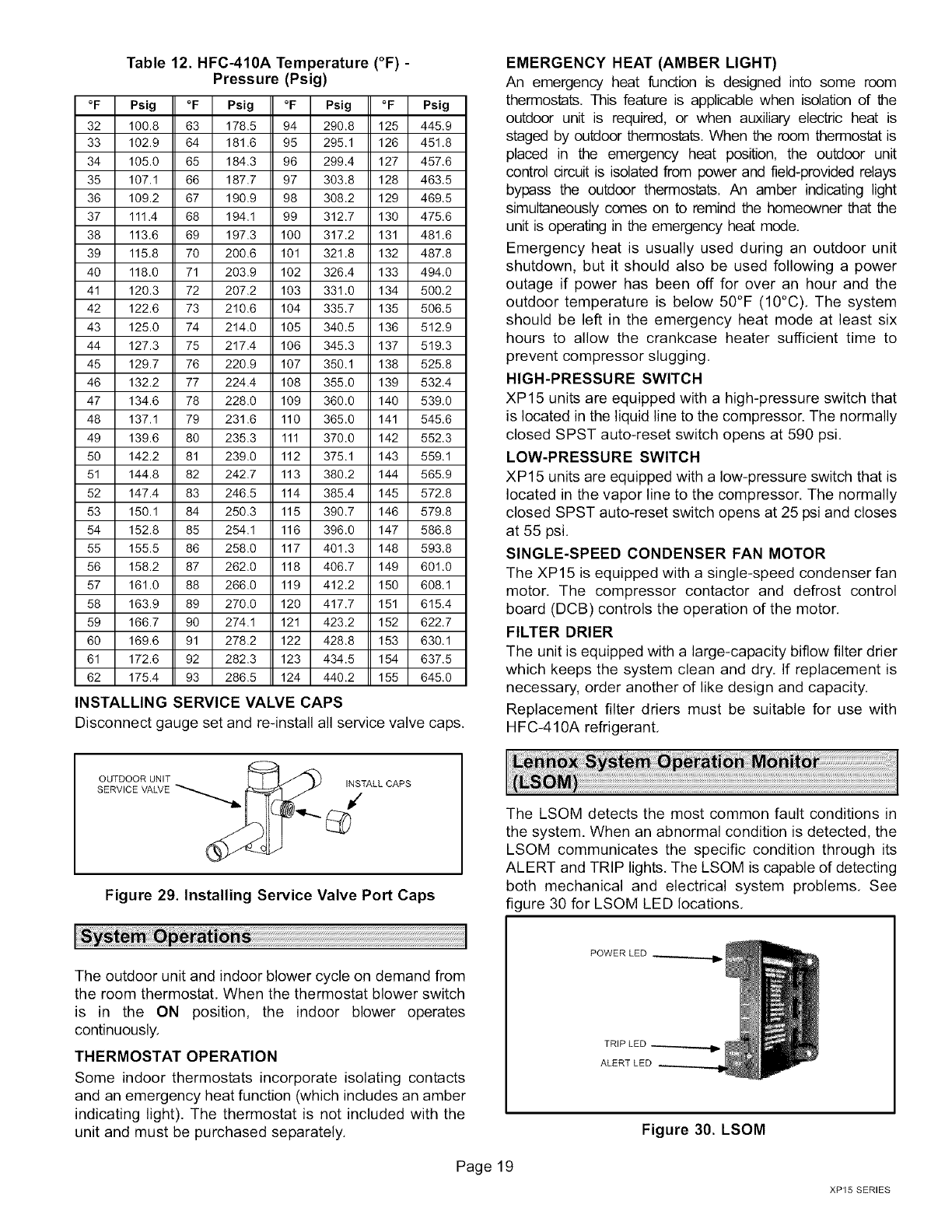
Table 12. HFC-410A Temperature (°F) -
Pressure (Psig)
°F Psig °F Psig °F Psig °F Psig
32 100.8 63 178.5 94 290.8 125 445.9
33 102.9 64 181.6 95 295.1 126 451.8
34 105.0 65 184.3 96 299.4 127 457.6
35 107.1 66 187.7 97 303.8 128 463.5
36 109.2 67 190.9 98 308.2 129 469.5
37 111.4 68 194.1 99 312.7 130 475.6
38 113.6 69 197.3 100 317.2 131 481.6
39 115.8 70 200.6 101 321.8 132 487.8
40 118.0 71 203.9 102 326.4 133 494.0
41 120.3 72 207.2 103 331.0 134 500.2
42 122.6 73 210.6 104 335.7 135 506.5
43 125.0 74 214.0 105 340.5 136 512.9
44 127.3 75 217.4 106 345.3 137 519.3
45 129.7 76 220.9 107 350.1 138 525.8
46 132.2 77 224.4 108 355.0 139 532.4
47 134.6 78 228.0 109 360.0 140 539.0
48 137.1 79 231.6 110 365.0 141 545.6
49 139.6 80 235.3 111 370.0 142 552.3
50 142.2 81 239.0 112 375.1 143 559.1
51 144.8 82 242.7 113 380.2 144 565.9
52 147.4 83 246.5 114 385.4 145 572.8
53 150.1 84 250.3 115 390.7 146 579.8
54 152.8 85 254.1 116 396.0 147 586.8
55 155.5 86 258.0 117 401.3 148 593.8
56 158.2 87 262.0 118 406.7 149 601.0
57 161.0 88 266.0 119 412.2 150 608.1
58 163.9 89 270.0 120 417.7 151 615.4
59 166.7 90 274.1 121 423.2 152 622.7
60 169.6 91 278.2 122 428.8 153 630.1
61 172.6 92 282.3 123 434.5 154 637.5
62 175.4 93 286.5 124 440.2 155 645.0
INSTALLING SERVICE VALVE CAPS
Disconnect gauge set and re-install all service valve caps.
EMERGENCY HEAT (AMBER LIGHT)
An emergency heat function is designed into some room
thermostats. This feature is applicable when isolation of the
outdoor unit is required, or when auxiliary electric heat is
staged by outdoor thermostats. When the room thermostat is
placed in the emergency heat position, the outdoor unit
control circuit is isolated from power and field-provided relays
bypass the outdoor thermostats. An amber indicating light
simultaneously comes on to remind the homeowner that the
unit is operating in the emergency heat mode.
Emergency heat is usually used during an outdoor unit
shutdown, but it should also be used following a power
outage if power has been off for over an hour and the
outdoor temperature is below 50°F (10°C), The system
should be left in the emergency heat mode at least six
hours to allow the crankcase heater sufficient time to
prevent compressor slugging.
HIGH-PRESSURE SWITCH
XP15 units are equipped with a high-pressure switch that
is located in the liquid line to the compressor. The normally
closed SPST auto-reset switch opens at 590 psi,
LOW-PRESSURE SWITCH
XP15 units are equipped with a low-pressure switch that is
located in the vapor line to the compressor. The normally
closed SPST auto-reset switch opens at 25 psi and closes
at 55 psi,
SINGLE-SPEED CONDENSER FAN MOTOR
The XP15 is equipped with a single-speed condenser fan
motor. The compressor contactor and defrost control
board (DCB) controls the operation of the motor,
FILTER DRIER
The unit is equipped with a large-capacity biflow filter drier
which keeps the system clean and dry. If replacement is
necessary, order another of like design and capacity,
Replacement filter driers must be suitable for use with
HFC-410A refrigerant,
OUTDOOR UNIT INSTALL CAPS
SERVICE VALVE _ _/
Figure 29. Installing Service Valve Port Caps
The LSOM detects the most common fault conditions in
the system. When an abnormal condition is detected, the
LSOM communicates the specific condition through its
ALERT and TRIP lights, The LSOM is capable of detecting
both mechanical and electrical system problems. See
figure 30 for LSOM LED locations.
The outdoor unit and indoor blower cycle on demand from
the room thermostat, When the thermostat blower switch
is in the ON position, the indoor blower operates
continuously.
THERMOSTAT OPERATION
Some indoor thermostats incorporate isolating contacts
and an emergency heat function (which includes an amber
indicating light). The thermostat is not included with the
unit and must be purchased separately,
Page 19
POWER LED .....
TRIP LED
ALERT LED
Figure 30. LSOM
XP15 SERIES
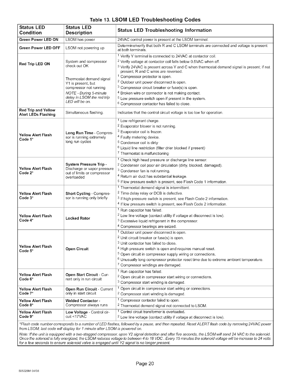
Table 13. LSOM LED Troubleshooting Codes
Status LED Status LED Status LED Troubleshooting Information
Condition Description
Green Power LED ON LSOM has power
Green Power LED OFF LSOM not powering up
System and compressor
check out OK
Thermostat demand signal
Y1 is present, but
compressor not running
NO TE -During 5-minute
delay in LSOM the red trip
LED will be on.
Red Trip LED ON
Red Trip and Yellow
Alert LEDs Flashing Simultaneous flashing,
Yellow Alert Flash
Code 1"
Yellow Alert Flash
Code 2*
Yellow Alert Flash
Code 3*
Yellow Alert Flash
Code 4*
Long Run Time - Compres-
sor is running extremely
long run cycles
System Pressure Trip -
Discharge or vapor pressure
out of limits or compressor
overloaded
Short Cycling -Compres-
sor is running only briefly
Locked Rotor
Open Circuit
Yellow Alert Flash
Code 5*
Yellow Alert Flash Open Start Circuit -Cur-
Code 6* rent only in run circuit
Yellow Alert Flash Open Run Circuit - Current
Code 7* only in start circuit
Yellow Alert Flash Welded Contactor -
Code 8* Compressor always runs
Yellow Alert Flash Low Voltage - Control cir-
Code 9* cuit <17VAC
24VAC control power is present at the LSOM terminal.
Determine/verify that both R and C LSOM terminals are connected and voltage is present
at both terminals.
1 Verify Y terminal is connected to 24VAC at contactor coil.
2 Verify voltage at contactor coil falls below 0.5VAC when off.
3 Verify 24VAC is present across Y and C when thermostat demand signal is present; if not
present, R and C wires are reversed.
1 Compressor protector is open.
2 Outdoor unit power disconnect is open.
3 Compressor circuit breaker or fuse(s) is open.
4 Broken wire or connector is not making contact.
5 Low pressure switch open if present in the system.
6 Compressor contactor has failed to close.
Indicates that the control circuit voltage is too low for operation.
1 LOW refrigerant charge.
2 Evaporator blower is not running.
3 Evaporator coil is frozen.
4 Faulty metering device.
5 Condenser coil is dirty.
6 Liquid line restriction (filter drier blocked if present).
7 Thermostat is malfunctioning.
1 Check high head pressure or discharge line sensor.
2 Condenser coil poor air circulation (dirty, blocked, damaged).
3 Condenser fan is not running.
4 Return air duct has substantial leakage.
5 If low pressure switch is present, see Flash Code 1 information.
1 Thermostat demand signal is intermittent.
2 Time delay relay or DCB is defective.
3 If high pressure switch is present, see Flash Code 2 information.
4 If low pressure switch is present, see Flash Code 2 information.
1 Run capacitor has failed.
2 Low line voltage (contact utility if voltage at disconnect is low).
3 Excessive liquid refrigerant in the compressor.
4 Compressor bearings are seized.
1 Outdoor unit power disconnect is open.
2 Unit circuit breaker or fuse(s) is open.
3 Unit contactor has failed to close.
4 High pressure switch is open and requires manual reset.
5 Open circuit in compressor supply wiring or connections.
6 Unusually long compressor protector reset time due to extreme ambient temperature.
7 Compressor windings are damaged.
1 Run capacitor has failed.
2 Open circuit in compressor start wiring or connections.
3 Compressor start winding is damaged.
1 Open circuit in compressor start wiring or connec_ons.
2 Compressor start winding is damaged.
1 Compressor contactor failed to open.
2 Thermostat demand signal not connected to LSOM.
1 Control circuit transformer is overloaded.
2 Low line voltage (contact utility if voltage at disconnect is low).
*Flash code number corresponds to a number of LED flashes, followed by a pause, and then repeated. Reset ALER Tflash code by removing 24VAC power
from LSOM; last code will display for 1 minute after LSOM is powered on.
Note: If the unit is equipped with a two-stagged compressor, upon Y2 signal detection and after five seconds, the LSOM will send 24 VAC to the solenoid.
Once the solenoid is fully energized, the L SOM reduces voltage to between 4 to 18 VDC .Every 15 minutes the solenoid voltage will be increase to 24 volts
for a few seconds to ensure solenoid valve is engaged until Y2 signal is no longer present.
505328M 04_8
Page 20
LSOM--LED Functions
AIMPORTANT
See table 13 on page 20 for the complete explanation of
troubleshooting codes.
LED Function Description
Color
Indicates voltage within the range of
Green Power 19-28VAC is present at LSOM con-
nection.
Yellow Alert
Communicates an abnormal system
condition through a unique flash code.
The alert LED flashes a number of
times consecutively; then pauses;
then repeats the process. This
consecutive flashing correlates to a
particular abnormal condition.
Indicates there is a demand signal
from the thermostat but no current to
Red Trip the compressor is detected by the
LSOM.
Resetting Alert Codes
Alert codes can be reset manually or automatically:
Cycle the 24VAC power to LSOM off and on. Af-
Manual ter power up, existing code will display for one
minute and then clear.
After an alert is detected, the LSOM continues
Automatic to monitor the compressor and system. Whentif
conditions return to normal, the alert code is
turned off automatically.
LSOM--L Terminal Connection
The L connection is used to communicate alert codes to
the room thermostat. On selected Lennox SignatureStat"
thermostats, a blinking check LED will display on the room
thermostat and on select White-Rodgers room
thermostats, an icon on the display will flash. Either will
flash at the same rate as the LSOM yellow alert LED,
NOTE -ROOM THERMOSTATS WITH SERVICE OR
CHECK LIGHT FEATURE--The room thermostat may
blink the Check or Service LED or it may come on sofid,
Confirm fault by observing and interpreting the code from
the LSOM yellow alert LED at the unit,
LSOM--Installation Verification
To verify correct LSOM installation, two functional tests
can be performed.
TEST 1:
1. Disconnect power from the compressor and force a
thermostat call for cooling.
2. The red trip LED should turn on indicating a
compressor trip as long as 24VAC is measured at the
Y terminal, If the red LED does not function as
described, refer to table 13 on page 20 to verify the
wiring,
TEST 2:
1. Disconnect power from the compressor and 24VAC
power from the LSOM
2. Remove the wire from the Y terminal of LSOM and
reapply power to the compressor, allowing the
compressor to run. The yellow alert LED will begin
flashing a code 8 indicating a welded contactor,
3. While the LSOM is off, reattach the wire to the Y
terminal,
4. Reapply power to the compressor and 24VAC power
to the LSOM; the yellow alert LED will flash the
previous code 8 for one minute and then turn off. If the
yellow LED does not function as described, refer to
table 13 on page 20 to verify the wiring,
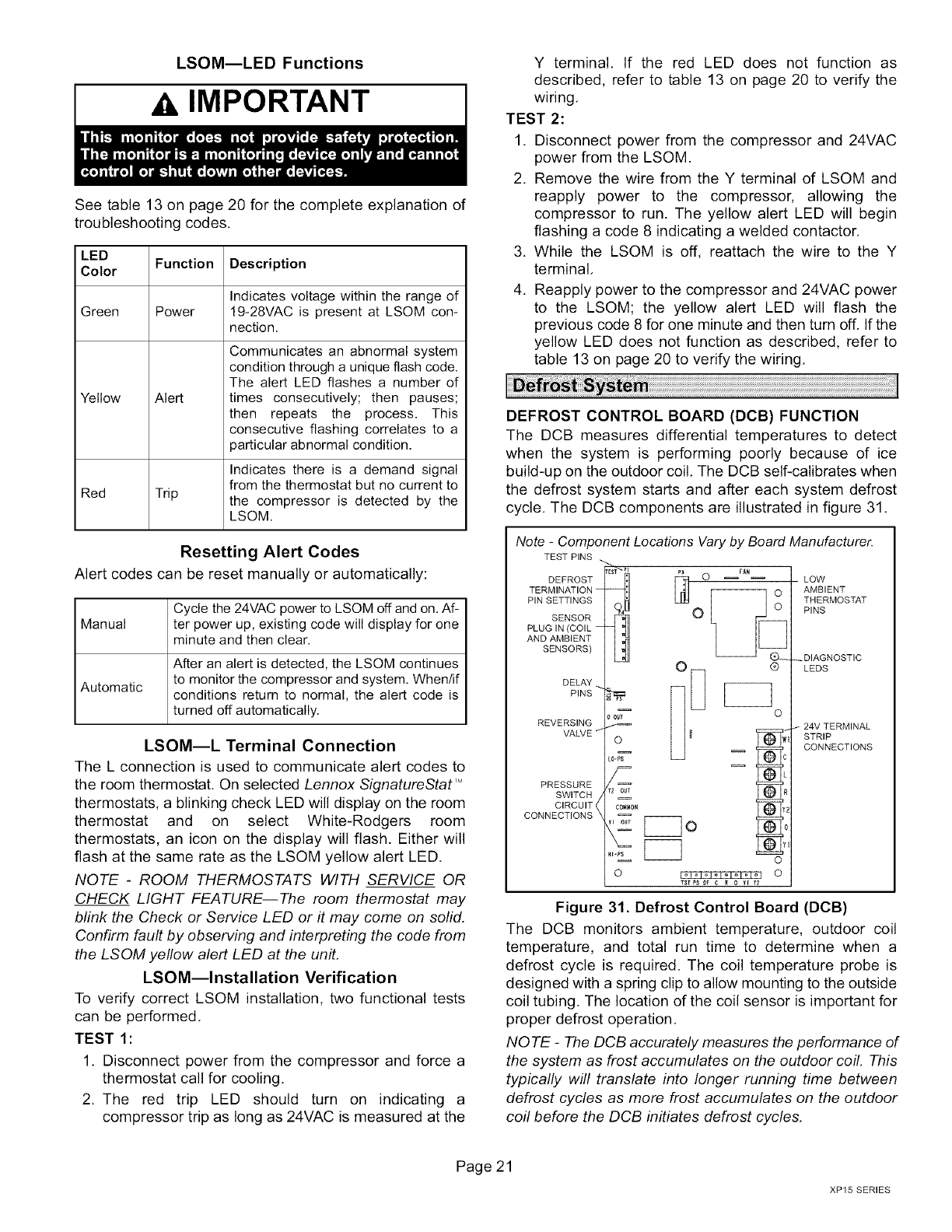
DEFROST CONTROL BOARD (DCB) FUNCTION
The DCB measures differential temperatures to detect
when the system is performing poorly because of ice
build-up on the outdoor coil. The DCB self-calibrates when
the defrost system starts and after each system defrost
cycle. The DCB components are illustrated in figure 31.
Note -Component Locations Vary by Board Manufacturer.
TEST PINS
DEFROST
TERMINATION
PIN SETTINGS
SENSOR
PLUG IN (COIL
AND AMBIENT
SENSORS)
DELAY
PINS
REVERSING
VALVE
PRESSURE
SWITCH
CIRCUIT
CONNECTIONS
rEs_ PI [_ O rAN
°
o_7 o
Owl
0-Ps
¢0_MON _2
TStPS O_ C _ 0 v_ _2
LOW
AMBIENT
THERMOSTAT
PINS
_DIAGNOSTIC
LEDS
24V TERMINAL
STRIP
CONNECTIONS
Figure 31. Defrost Control Board (DCB)
The DCB monitors ambient temperature, outdoor coil
temperature, and total run time to determine when a
defrost cycle is required. The coil temperature probe is
designed with a spring clip to allow mounting to the outside
coil tubing. The location of the coil sensor is important for
proper defrost operation.
NOTE -The DCB accurately measures the performance of
the system as frost accumulates on the outdoor coil. This
typically will translate into longer running time between
defrost cycles as more frost accumulates on the outdoor
coil before the DCB initiates defrost cycles.
Page 21
XP15 SERIES
Pressure Switch Connections
The unit's automatic reset pressure switches (LO PS - $87
and HI PS - $4) are factory-wired into the DCB on the
LO-PS and HI-PS terminals, respectively.
Pressure Switch Event Settings
The following are the auto reset event values for low and
high pressures thresholds:
•High Pressure (auto reset) - trip at 590 psig, reset to
418 psig.
• Low Pressure (auto reset) - trip at 25 psig, reset to 55
psig.
Five-Strike Lockout Safety Function
The five-strike lockout safety function is designed to
protect the unit's compressor from damage. The DCB
monitors for an active state on the DCB's Y1 input as
referenced in figure 31 on page 21. When the Y1 input is
active the internal control logic of the DCB will do the
following:
• Count any HI-PS and LO-PS pressure switch trips
(open and close).
• If a pressure switch trips four times during the current
active state on the Y1 input, then the DCB's control
logic will reset the pressure switch trip counter to zero
at the end of currently active Y1 input state.
• If the pressure switch opens for a fifth time during the
current Y1 input state, the DCB will enter a lockout
condition.
The system will require servicing to determine the cause of
the pressure switch condition. Once the condition has
been rectified, use the following procedure to reset the
DCB.
DEFROST SYSTEM SENSORS
Sensors connect to the DCB through a field-replaceable
harness assembly that plugs into the DCB. Through the
sensors, the DCB detects outdoor ambient and coil
temperature fault conditions. As the detected temperature
changes, the resistance across the sensor changes.
Sensor resistance values can be checked by ohming
across pins shown in table 14.
NOTE -When checking the ohms across a sensor, be
aware that a sensor showing a resistance value that is not
within the range shown in table 14, may be performing as
designed. However, if a shorted or open circuit is detected,
then the sensor may be faulty and the sensor harness will
need to be replaced.
Table 14. Sensor Temperature /Resistanc4 Range
Temperature Resistance values Pins/Wire
Sensor Range °F (°C) range (ohms) Color
Outdoor -35 (-37) to 120 280,000 to 3750 3 and 4
(48) (Black)
Coil -35 (-37) to 120 280,000 to 3750 5 and 6
(48) (Brown)
Note: Sensor resistance increases as sensed temperature
decreases.
Ambient Sensor--The ambient sensor as illustrated in
figure 32 on page 24 considers outdoor temperatures
below -35°F (-37°C) or above 120°F (48°C) as a fault. If the
ambient sensor is detected as being open, shorted or out
of the temperature range of the sensor, the DCB will not
perform demand defrost operation. The DCB will revert to
time/temperature defrost operation and will display the
appropriate fault code. Heating and cooling operation will
be allowed in this fault condition,
Coil Sensor--The coil temperature sensor as illustrated
in figure 32 on page 24, considers outdoor temperatures
below -35°F (-37°C) or above 120°F (48°C) as a fault. If the
coil temperature sensor is detected as being open, shorted
or out of the temperature range of the sensor, the DCB will
not perform demand or time/temperature defrost
operation and will display the appropriate fault code.
Heating and cooling operation will be allowed in this fault
condition.
NOTE -Within a single room thermostat demand, if
five-strikes occur, the DCB will lock out the unit. The DCB's
24 volt power R must be cycled OFF, or the TESTpins on
DCB must be shorted between 1 to 2 seconds to reset the
DCB.
DCB OPERATIONAL MODES
The DCB has four basic operational modes which are
TEST, NORMAL CALIBRATION and DEFROST.
TEST
1. When Y1 is energized and 24V power is being applied
to the DCB, a test cycle can be initiated by: placing the
termination temperature jumper across the Test pins
(P1) for 2 to 5 seconds.
2. If the jumper remains across the Test pins longer than
five seconds, the DCB will ignore the test pins and
revert to normal operation,
3. The jumper will initiate one cycle per test.
4, Enter the TEST MODE by placing a jumper across the
TEST pins on the DCB after power-up. The TEST pins
are ignored and the test function is locked out if the
shunt is applied on the TEST pins before power-up.
5, DCB timings are reduced, the low-pressure switch is
ignored and the DCB will clear any active lock out
condition,
6, Each test pin shorting will result in one test event, For
each TEST the jumper must be removed for at least
one second and reapplied, Refer to flow chart
illustrated in figure 33 on page 24 for TEST operation,
NOTE -The Y1 input must be active (ON) and the 0 room
thermostat terminal into DCB must be inactive
NORMAL
The DCB monitors the O line, to determine the system
operating mode (heat/cool), outdoor ambient temperature,
coil temperature (outdoor coil) and compressor run time to
determine when a defrost cycle is required,
CALIBRATION
The DCB is considered uncalibrated when power is
applied to the DCB, after cool mode operation, or if the coil
temperature exceeds the termination temperature when it
is in heat mode.
DEFROST
For detail information on DEFROST MODE, see Detail
Defrost Mode Operation on page 26.
Page 22
505328M 04/08
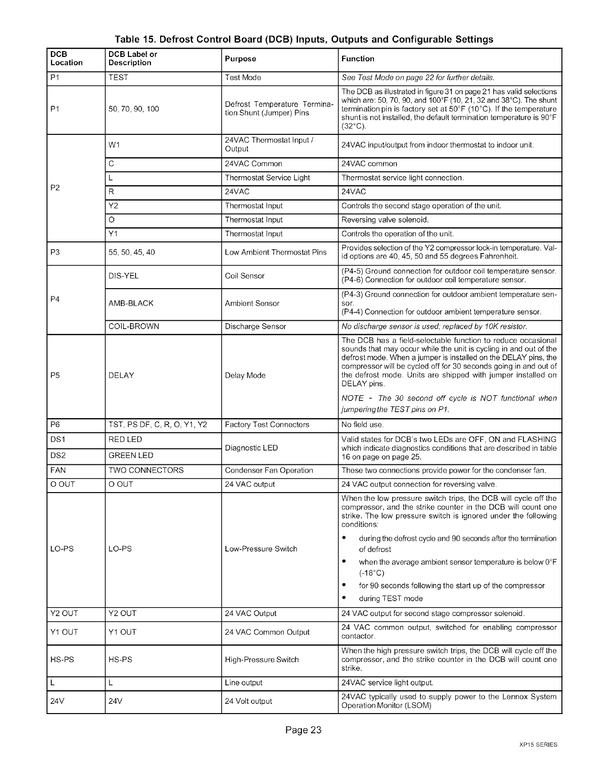
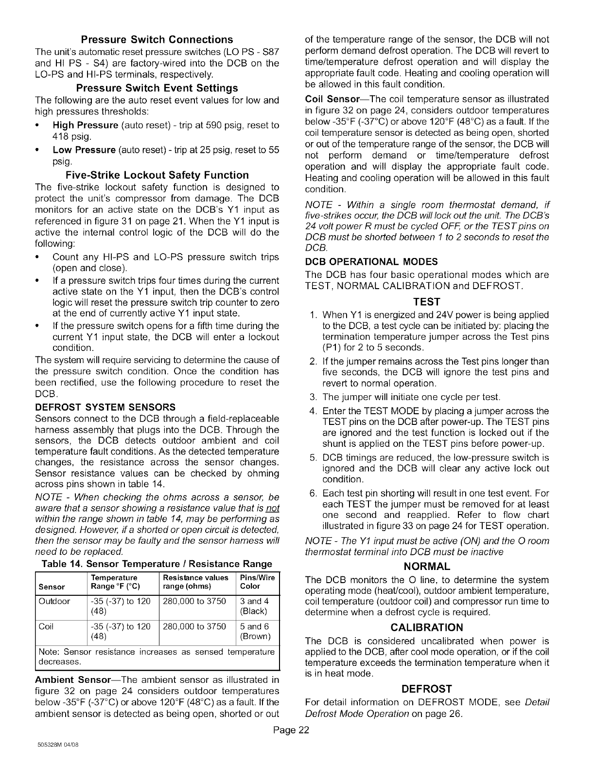
Table 15. Defrost Control Board (DCB) Inputs, Outputs and Configurable Settings
DCB DCB Label or
Location Description Purpose Function
P1 TEST Test Mode
Defrost Temperature Termina-
P1 50, 70, 90, 100 tion Shunt (Jumper) Pins
24VAC Thermostat Input /
Wl Output
C 24VAC Common
L Thermostat Service Light
P2 R 24VAC
Y2 Thermostat Input
O Thermostat Input
Y1 Thermostat Input
P3 55, 50, 45, 40 Low Ambient Thermostat Pins
DIS-YEL Coil Sensor
P4 AMB-BLACK Ambient Sensor
COIL-BROWN Discharge Sensor
P5
P6
DS1
DS2
FAN
O OUT
LO-PS
DELAY
TST, PS DF, C, R, O, Y1, Y2
RED LED
GREEN LED
TWO CONNECTORS
O OUT
LO-PS
Delay Mode
Factory Test Connectors
Diagnostic LED
Condenser Fan Operation
24 VAC output
Low-Pressure Switch
Y2 OUT Y2 OUT 24 VAC Output
Y1 OUT Y1 OUT 24 VAC Common Output
HS-PS HS-PS High-Pressure Switch
L Line output
24V 24V 24 Volt output
See Test Mode on page 22 for further details.
The DCB as illustrated in figure 31 on page 21 has valid selections
which are: 50, 70, 90, and 100°F (10, 21,32 and 38°C), The shunt
termination pin is factory set at 50°F (10°C). If the temperature
shunt is not installed, the default termination temperature is 90°F
(32°C).
24VAC input/output from indoor thermostat to indoor unit.
24VAC common
Thermostat service light connection,
24VAC
Controls the second stage operation of the unit,
Reversing valve solenoid.
Controls the operation of the unit,
Provides selection of the Y2 compressor lock-in temperature. Val-
id options are 40, 45, 50 and 55 degrees Fahrenheit,
(P4-5) Ground connection for outdoor coil temperature sensor.
(P4-6) Connection for outdoor coil temperature sensor.
(P4-3) Ground connection for outdoor ambient temperature sen-
sor.
(P4-4) Connection for outdoor ambient temperature sensor.
No discharge sensor is used, replaced by !OK resistor.
The DCB has a field-selectable function to reduce occasional
sounds that may occur while the unit is cycling in and out of the
defrost mode. When a jumper is installed on the DELAY pins, the
compressor will be cycled off for 30 seconds going in and out of
the defrost mode. Units are shipped with jumper installed on
DELAY pins.
NOTE -The 30 second off cycle is NOT functional when
jumperingthe TES Tpins on P1.
No field use.
Valid states for DCB's two LEDs are OFF, ON and FLASHING
which indicate diagnostics conditions that are described in table
16 on page on page 25.
These two connections provide power for the condenser fan.
24 VAC output connection for reversing valve.
When the low pressure switch trips, the DCB will cycle off the
compressor, and the strike counter in the DCB will count one
strike. The low pressure switch is ignored under the following
conditions:
• during the defrost cycle and 90 seconds after the termination
of defrost
• when the average ambient sensor temperature is below 0°F
(-18°C)
• for 90 seconds following the start up of the compressor
• during TEST mode
24 VAC output for second stage compressor solenoid.
24 VAC common output, switched for enabling compressor
contactor.
When the high pressure switch trips, the DCB will cycle off the
compressor, and the strike counter in the DCB will count one
strike.
24VAC service light output,
24VAC typically used to supply power to the Lennox System
Operation Monitor (LSOM)
Page23
XP15 SERIES
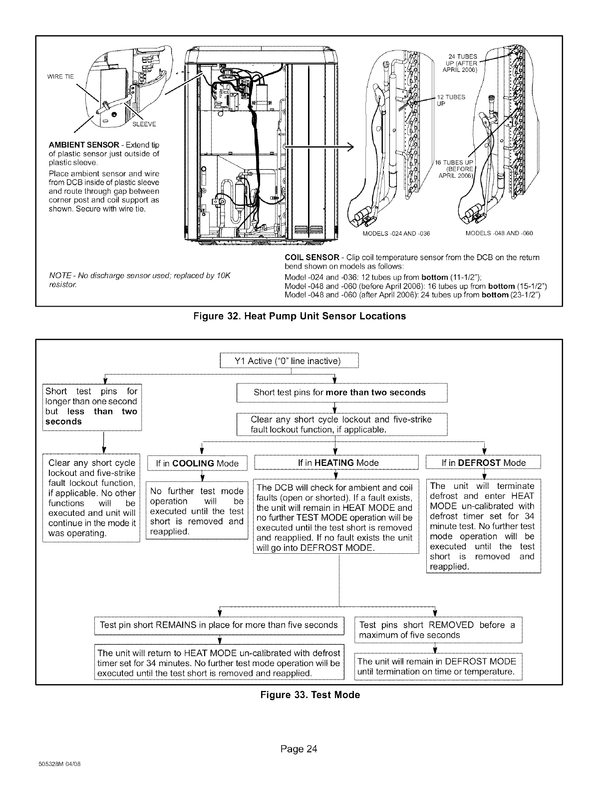
WIRETIE
\
SLEEVE
AMBIENT SENSOR - Extend tip
of plastic sensor just outside of
plastic sleeve.
Place ambient sensor and wire
from DCB inside of plastic sleeve
and route through gap between
corner post and coil support as
shown. Secure with wire tie.
MODELS -024 AND -036
24 TUBES
UP
APRIL 2006)
/
12 TUBES /
UP
16 TUBES UP
/
MODELS -048 AND -060
NOTE- No discharge sensor used; replaced by fOK
resistor
COIL SENSOR - Clip coil temperature sensor from the DCB on the return
bend shown on models as follows:
Model -024 and -036:12 tubes up from bottom (11-1/2");
Model -048 and -060 (before April 2006): 16 tubes up from bottom (15-1/2")
Model -048 and -060 (after April 2006): 24 tubes up from bottom (23-1/2")
Figure 32. Heat Pump Unit Sensor Locations
Short test pins for
Iongerthan one second
but less than two
seconds
Clear any short cycle
lockout and five-strike
fault lockout function,
if applicable. No other
functions will be
executed and unit will
continue in the mode it
was operating.
1
Y1 Active ("0" line inactive) /
Short test pins for more than two seconds
L
No further test mode
operation will be
executed until the test
short is removed and
reapplied.
Clear any short cycle lockout and five-strike
fault lockout function, if applicable.
.finOO0.,N ModeII .fin.E T,N Mode II
The DCB will check for ambient and coil
faults (open or shorted). If a fault exists,
the unit will remain in HEAT MODE and
no further TEST MODE operation will be
executed until the test short is removed
and reapplied. If no fault exists the unit
will go into DEFROST MODE.
If in DEFROST Mode ]
The unit will terminate
defrost and enter HEAT
MODE un-calibrated with
defrost timer set for 34
minute test. No further test
mode operation will be
executed until the test
short is removed and
reapplied.
Test pin short REMAINS in place for more than five seconds
The unit will return to HEAT MODE un-calibrated with defrost
timer set for 34 minutes. No further test mode operation will be
executed until the test short is removed and reapplied.
Test pins short REMOVED before a
maximum of five seconds
The unit will remain in DEFROST MODE
until termination on time or temperature.
Figure 33. Test Mode
505328M 04/08
Page 24
Table 16. DCB Diagnostic LEDs
DS2 DS1 Condition Possible Cause(s) Solution
Green Red
1 Check control transformer power (24V).
No power (24V) to DCB terminals R and 2 If power is available to DCB and LED(s) do not light,
OFF OFF Power problem C or DCB failure.
replace DCB.
SIMULTANEOUS Unit operating normally or in standby None required.
SLOW FLASH Normal operation mode.
ALTERNATING Initial power up, safety trip, end of room None required (Jumper TEST pins to override)
SLOW FLASH 5-minute anti-short cycle delay thermostat demand.
SIMULTANEOUS Sensor being detected open or shorted or out of temperature range. DCB will revert to
FAST FLASH Ambient sensor problem time/temperaturedefrost operation. (System will still heat or cool).
ALTERNATING Sensor being detected open or shorted or out of temperature range. DCB will not perform demand
FAST FLASH Coil sensor problem or time/temperature defrost operation. (System will still heat or cool).
ON Indicates that DCB has internal component failure. Cycle 24 volt power to DCB. If code does not
ON DCB failure clear, replace DCB.
FAULT and LOCKOUT CODES (Each fault adds 1 strike to that code's counter; 5 strikes per code = LOCKOUT)
1 Remove any blockages or restrictions from coils
SLOW
OFF FLASH Low pressure fault
OFF ON Low pressure lockout
SLOW
FLASH OFF High pressure fault
ON OFF High pressure lockout
1 Restricted air flow over indoor or out-
door coil.
2 Improper refrigerant charge in sys-
tem.
3 Improper metering device installed or
incorrect operation of metering de-
vice.
4 Incorrect or improper sensor location
or connection to system.
2
3
4
and/or fans. Check indoor and outdoor fan motor for
proper current draws.
Check system charge using approach and
subcooling temperatures.
Check system operating pressures and compare to
unit charging charts.
Make sure all pressure switches and sensors have
secure connections to system to prevent refrigerant
leaks or errors in pressure and temperature
measurements.
SLOW Discharge line temperature
FLASH ON fault
FAST
FLASH ON
FAST
OFF FLASH
FAST
FLASH OFF
Discharge line temperature
Lockout
Discharge sensor fault
Discharge sensorlockout
This code detects shorted sensor or high discharge temperatures. If the discharge line temperature
exceeds a temperature of 300°F (148°C) during compressor operation, the board will de-energize
the compressor contactor output (and the defrost output if active). The compressor will remain off
until the discharge temperature has dropped below 225°F (107°C).
The board detects open sensor or out of temperature sensor range. This fault is detected by allow-
ing the unit to run for 90 seconds before checking sensor resistance. Ifthe sensor resistance is not
within range after 90 seconds, the board will count one fault. After five faults, the board will lockout.
SLOW Discharge line temperature
FLASH ON fault
FAST Discharge line temperature
FLASH ON lockout
FAST
FLASH
OFF
Some heat pump units do not use a defrost line sensor. Therefore this code is not applicable.
Some heat pump units do not use a defrost line sensor. However, on these units a resistor is
OFF Discharge sensor fault installed across pins P4-1 and P4-2. If the resistor is missing or damaged then this fault code will
be displayed.
FAST Discharge sensor lockout
FLASH Some heat pump units do not use a defrost line sensor. Therefore this code is not applicable.
Page 25
XP15 SERIES
DETAILED DEFROST MODE OPERATION
The defrost mode has three basic operational modes
which are defrost cycles, actuation and termination, These
modes are described as follows:
Defrost Cycles--The demand DCB initiates a defrost
cycle based on either frost detection or time,
Event
Frost
Detection
Time
Description
If the compressor runs longer than 34
minutes and the actual difference between
the clear coil and frosted coil temperatures
exceeds the maximum difference allowed
by the DCB, a defrost cycle will be initiated.
IMPORTANT -The DCB will allow a
greater accumulation of frost and will
initiate fewer defrost cycles than a
time/temperature defrost system.
If six hours of heating mode compressor
run time has elapsed since the last defrost
cycle while the coil temperature remains
below 35°F (2°C), the DCB will initiate a
defrost cycle.
Actuation--When the reversing valve is de-energized,
the Y1 circuit is energized, and the coil temperature is
below 35°F (2°C), the DCB logs the compressor run time.
If the DCB is not calibrated, a defrost cycle will be initiated
after 34 minutes of heating mode compressor run time.
The DCB will attempt to self-calibrate after this (and all
other) defrost cycle(s),
Calibration success depends on stable system
temperatures during the 20-minute calibration period. If
the DCB fails to calibrate, another defrost cycle will be
initiated after 90 minutes of heating mode compressor run
time, Once the DCB is calibrated, it initiates a demand
defrost cycle when the difference between the clear coil
and frosted coil temperatures exceeds the maximum
difference allowed by the DCB or after six hours of heating
mode compressor run time has been logged since the last
defrost cycle,
NOTE -If ambient or coil fault is detected, the DCB will not
execute the TEST mode.
Termination--The defrost cycle ends when the coil
temperature exceeds the termination temperature or after
14 minutes of defrost operation, If the defrost is terminated
by the 14-minute timer, another defrost cycle will be
initiated after 34 minutes of run time,
DCB DIAGNOSTICS
See table 16 on page 25 to determine DCB operational
conditions and to diagnose cause and solution to
problems.
Before the start of each heating and cooling season, the
following service checks should be performed by a
qualified service technician. First, turn off electrical power
to the unit prior to performing unit maintenance.
_WARNING
• Inspect and clean the outdoor and indoor coils. The
outdoor coil may be flushed with a water hose.
NOTE -It may be necessary to flush the outdoor coil
more frequently if it is exposed to substances which
are corrosive or which block airflow across the coil
(e.g., pet urine, cottonwood seeds, etc.)
• Visually inspect the refrigerant lines and coils for leaks.
• Check wiring for loose connections.
• Check voltage at the indoor and outdoor units (with
units operating).
• Check the amperage draw at the outdoor fan motor,
compressor, and indoor blower motor. Values should
be compared with those given on unit nameplate.
• Check, clean (or replace) indoor unit filters.
• Check the refrigerant charge and gauge the system
pressures.
• Check the condensate drain line for free and
unobstructed flow; clean, if necessary.
• Outdoor unit fan motor is prelubricated and sealed. No
further lubrication is needed.
NOTE -If owner reports insufficient cooling, the unit
should be gauged and refrigerant charge checked.
Refer to section on refrigerant charging in this
instruction.
In order to ensure peak performance, your system must be
properly maintained. Clogged filters and blocked airflow
prevent your unit from operating at its most efficient level.
1, Air Filter--Ask your Lennox dealer to show you where
your indoor unit's filter is located. It will be either at the
indoor unit (installed internal or external to the cabinet)
or behind a return air grille in the wall or ceiling. Check
the filter monthly and clean or replace it as needed.
2, Disposable Filter--Disposable filters should be
replaced with a filter of the same type and size,
NOTE -If you are unsure about the filter required for
your system, call your Lennox dealer for assistance.
IMPORTANT
3, Reusable Filter--Many indoor units are equipped
with reusable foam filters. Clean foam filters with a
Page 26
505328M 04/08
mild soap and water solution; rinse thoroughly; allow
filter to dry completely before returning it to the unit or
grille.
NOTE -The filter and all access panels must be in
place any time the unit is in operation.
4, Electronic Air Cleaner--Some systems are
equipped with an electronic air cleaner, designed to
remove airborne particles from the air passing through
the cleaner. If your system is so equipped, ask your
dealer for maintenance instructions.
5. Indoor Unit--The indoor unit's evaporator coil is
equipped with a drain pan to collect condensate
formed as your system removes humidity from the
inside air. Have your dealer show you the location of
the drain line and how to check for obstructions. (This
would also apply to an auxiliary drain, if installed.)
IMPORTANT
6, Outdoor Unit--Make sure no obstructions restrict
airflow to the outdoor unit. Leaves, trash or shrubs
crowding the unit cause the outdoor unit to work harder
and use more energy. Keep shrubbery trimmed away
from the unit and periodically check for debris which
collects around the unit.
When removing debris from around the unit, be aware
of metal edges on parts and screws. Although special
care has been taken to keep exposed edges to a
minimum, physical contact with metal edges and
corners while applying excessive force or rapid motion
can result in personal injury.
Cleaning of the outdoor unit's coil should be performed
by a trained service technician. Contact your dealer
and set up a schedule (preferably twice a year, but at
least once a year) to inspect and service your heat
pump system.
HEAT PUMP OPERATION
Your new Lennox heat pump has several characteristics
that you should be aware of:
• Heat pumps satisfy heating demand by delivering
large amounts of warm air into the living space. This
is quite different from gas- or oil-fired furnaces or an
electric furnace which deliver lower volumes of
considerably hotter air to heat the space.
• Do not be alarmed if you notice frost on the outdoor coil
in the winter months. Frost develops on the outdoor
coil during the heating cycle when temperatures are
below 45°F (7°C). An electronic control activates a
defrost cycle lasting 5 to 15 minutes at preset intervals
to clear the outdoor coil of the frost.
• During the defrost cycle, you may notice steam rising
from the outdoor unit. This is a normal occurrence. The
thermostat may engage auxiliary heat during the
defrost cycle to satisfy a heating demand; however,
the unit will return to normal operation at the
conclusion of the defrost cycle.
EXTENDED POWER OUTAGE RESTART
PROCEDURE
The heat pump is equipped with a compressor crankcase
heater which protects the compressor from refrigerant
slugging during cold weather operation.
If power to your unit has been interrupted for several hours
or more, set the room thermostat selector to the
emergency heat setting to obtain temporary heat without
the risk of serious damage to the heat pump.
In emergency heat mode, all heating demand is satisfied
by auxiliary heat; heat pump operation is locked out. After a
six-hour compressor crankcase warm-up period, the
thermostat can be switched to the Heat setting and normal
heat pump operation may resume.
THERMOSTAT OPERATION
Though your thermostat may vary somewhat from the
description below, its operation will be similar.
Temperature Setting Levers
Most heat pump thermostats have two temperature
selector levers: one for heating and one for cooling. Set the
levers or dials to the desired temperature setpoints for both
heating and cooling. Avoid frequent temperature
adjustment; turning the unit off and back on before
pressures equalize puts stress on the unit compressor.
Fan Switch
In AUTO or INT (intermittent) mode, the blower operates
only when the thermostat calls for heating or cooling. This
mode is generally preferred when humidity control is a
priority. The ON or CONT mode provides continuous
indoor blower operation, regardless of whether the
compressor or auxiliary heat are operating. This mode is
required when constant air circulation or filtering is desired.
System Switch
Set the system switch for heating, cooling or auto
operation. The auto mode allows the heat pump to
automatically switch from heating mode to cooling mode to
maintain predetermined comfort settings. Many heat
pump thermostats are also equipped with an emergency
heat mode which locks out heat pump operation and
provides temporary heat supplied by the auxiliary heat.
Indicating Light
Most heat pump thermostats have an amber light which
indicates when the heat pump is operating in the
emergency heat mode.
Temperature Indicator
The temperature indicator displays the actual room
temperature.
Page27
XP15 SERIES
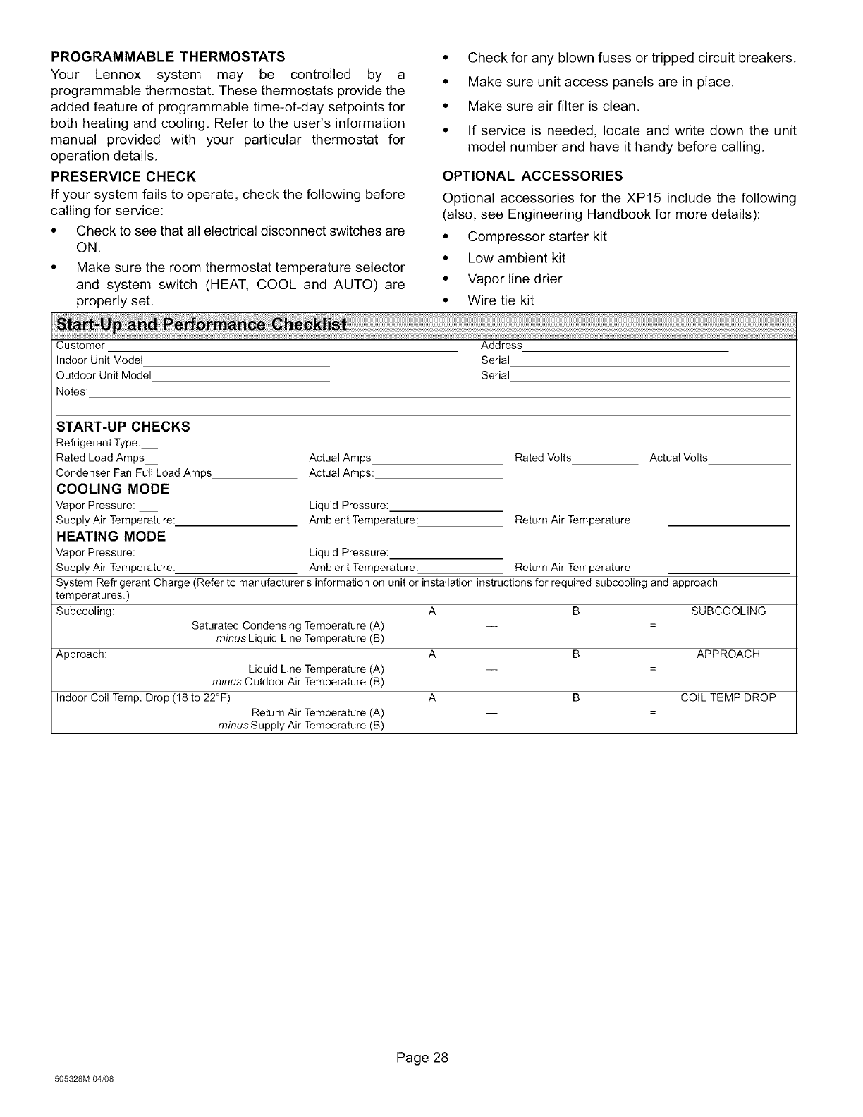
PROGRAMMABLE THERMOSTATS
Your Lennox system may be controlled by a
programmable thermostat, These thermostats provide the
added feature of programmable time-of-day setpoints for
both heating and cooling, Refer to the user's information
manual provided with your particular thermostat for
operation details,
PRESERVlCE CHECK
If your system fails to operate, check the following before
calling for service:
• Check to see that all electrical disconnect switches are
ON,
• Make sure the room thermostat temperature selector
and system switch (HEAT, COOL and AUTO) are
properly set,
• Check for any blown fuses or tripped circuit breakers.
• Make sure unit access panels are in place.
• Make sure air filter is clean.
• If service is needed, locate and write down the unit
model number and have it handy before calling.
OPTIONAL ACCESSORIES
Optional accessories for the XP15 include the following
(also, see Engineering Handbook for more details):
• Compressor starter kit
• Low ambient kit
• Vapor line drier
• Wire tie kit
Customer Address
Indoor Unit Model Serial
Outdoor Unit Model Serial
Notes:
START-UP CHECKS
Refrigerant Type:
Rated Load Amps
Condenser Fan Full Load Amps
COOLING MODE
Vapor Pressure:
Supply Air Temperature:
HEATING MODE
Actual Amps
Actual Amps:
Liquid Pressure:
Ambient Temperature:
SUBCOOLING
APPROACH
COIL TEMP DROP
Rated Volts Actual Volts
Return Air Temperature:
Vapor Pressure: Liquid Pressure:
Supply Air Temperature: Ambient Temperature: Return Air Temperature:
System Refrigerant Charge (Refer to manufacturer's information on unit or installation instructions for required subcooling and approach
temperatures.)
Subcooling: A B
Saturated Condensing Temperature (A)
minus Liquid Line Temperature (B)
Approach: A B
Liquid Line Temperature (A)
minus Outdoor Air Temperature (B)
Indoor Coil Temp. Drop (18 to 22°F) A B
Return Air Temperature (A)
minus Supply Air Temperature (B)
505328M 04/08
Page 28
