LENNOX Package Units(both Units Combined) Manual L0806659
User Manual: LENNOX LENNOX Package Units(both units combined) Manual LENNOX Package Units(both units combined) Owner's Manual, LENNOX Package Units(both units combined) installation guides
Open the PDF directly: View PDF ![]() .
.
Page Count: 28
TeCh nical
blications
Litho U.S.A.
,_,_2007
INSTALLATION
INSTRUCTIONS
_,WARNING
RETAIN THESE INSTRUCTIONS
FOR FUTURE REFERENCE
THA024 (2 TON)
THA030 (2-1/2 TON)
THA036 (3 TON)
THA048 (4TON)
THA060 (5TON)
THA072 (6TON)
Dimensions ................................. Page 1
Shipping and Packing List .................... Page 2
General .................................... Page 2
Requirements ............................... Page 2
Unit Support ................................ Page 3
Duct Connection ............................ Page 3
Rigging Unit For Lifting ....................... Page 3
Condensate Drains .......................... Page 4
HEAT PUMP PACKAGED UNITS
505,308M
6/2007
Supersedes 505,098M
Blower Operation and Adjustments ............ Page 9
Heating Start-Up ............................ Page 23
Cooling Start-Up ............................ Page 23
Defrost Control Board ........................ Page 26
Electrical Connections ....................... Page 6 Service .................................... Page 26
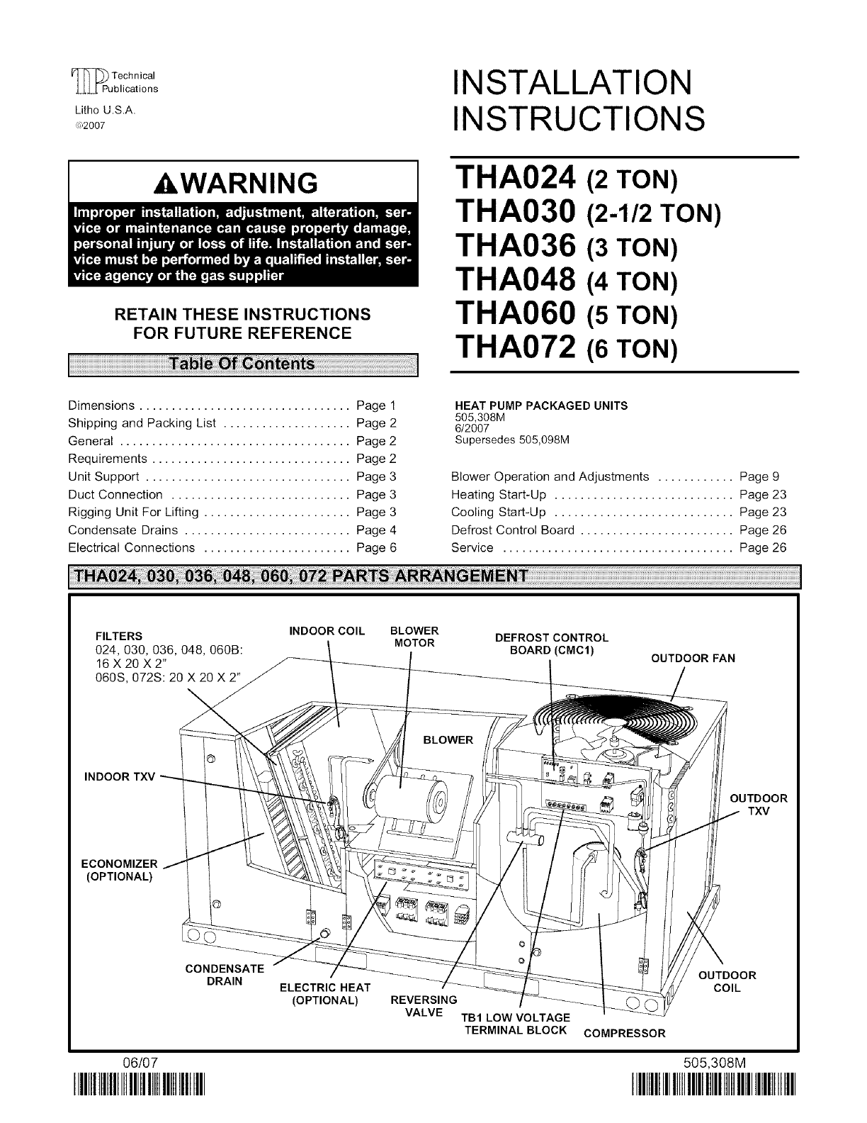
FILTERS INDOOR COIL BLOWER
MOTOR
024,030, 036, 048, 060B:
16 X 20 X2"
060S, 072S: 20 X 20 X 2"
DEFROST CONTROL
BOARD (CMC1) OUTDOORFAN
INDOOR TXV
OUTDOOR
TXV
ECONOMIZER
(OPTIONAL)
CONDENSATE
DRAIN
06/07
IIIBIIIIIIIIIIIIIIIIIIIIIIIIIIIIIIIII
ELECTRIC HEAT
(OPTIONAL) REVERSING
VALVE TB1 LOW VOLTAGE
TERMINAL BLOCK
OUTDOOR
COIL
COMPRESSOR
505,308M
IIIlllIIIIIIIIIIIIIIIIIHIIIIIIlllIIIII

45/ .11..1 1/.T18
'_ BOTTOM
47 / I I BOTTOM _ !r \\\_N_z::_j////
Base// I I S&q_LY--+
_ I I I CENTER_T_+_ 53/4
_1-- 26-1/2 -_ _ _1- _ 38"112"-I_"
BOTTOM BOTTOM POWER ENTRY
CONDENSATE OUTLET (3 x 8)
TOP VIEW (Base)
45
oo _ _ oo1_
47
_-- Base
END VIEW
q
04
o_ o
o__ o_ CONDEN-
i _1- i
.. o.. SATE
'- _ OUTLET
_ _ (Either Side)
5_ I,oo E
_//_ 261/2 _1_"
LIFTING HOLES "I111
(For rigging) I
83-1/4
_, 5-1/2
85-1/4
Base
ELECTRICAL I
ool
P
SIDE VIEW
ll
II
OO
FORKLIFT SLOTS
(Front, Back and Blower End)
III
qzz_ //
J/
HORIZONTAL
SUPPLY AIR
OPENING
F
CCCC] /o I _/2
5-!/2 HORIZONTAL
RETURN AIR
OPENING
Page 1
Package 1 of 1 contains:
1 - Assembled unit
Check unit for shipping damage. Receiving party should
contact last carrier immediately if shipping damage is
found,
These instructions are intended as a general guide and
do not supersede local codes in any way. Authorities
having jurisdiction should be consulted before
installation,
Availability of units and options varies by brand,
The THA unit is ETL/CSA certified as a heat pump with
cooling and with or without auxiliary electric heat for
non-residential use only at the clearances to combustible
materials as listed on the unit nameplate and in figure 1.
Installation of THA heat pumps must conform with
standards in National Fire Protection Association (NFPA)
"Standard for Installation of Air Conditioning and
Ventilating Systems NFPA No. 90A," "Standard for
Installation of Residence Type Warm Air Heating and Air
conditioning Systems NFPA No. 90B," local municipal
building codes and manufacturer's installation
instructions.
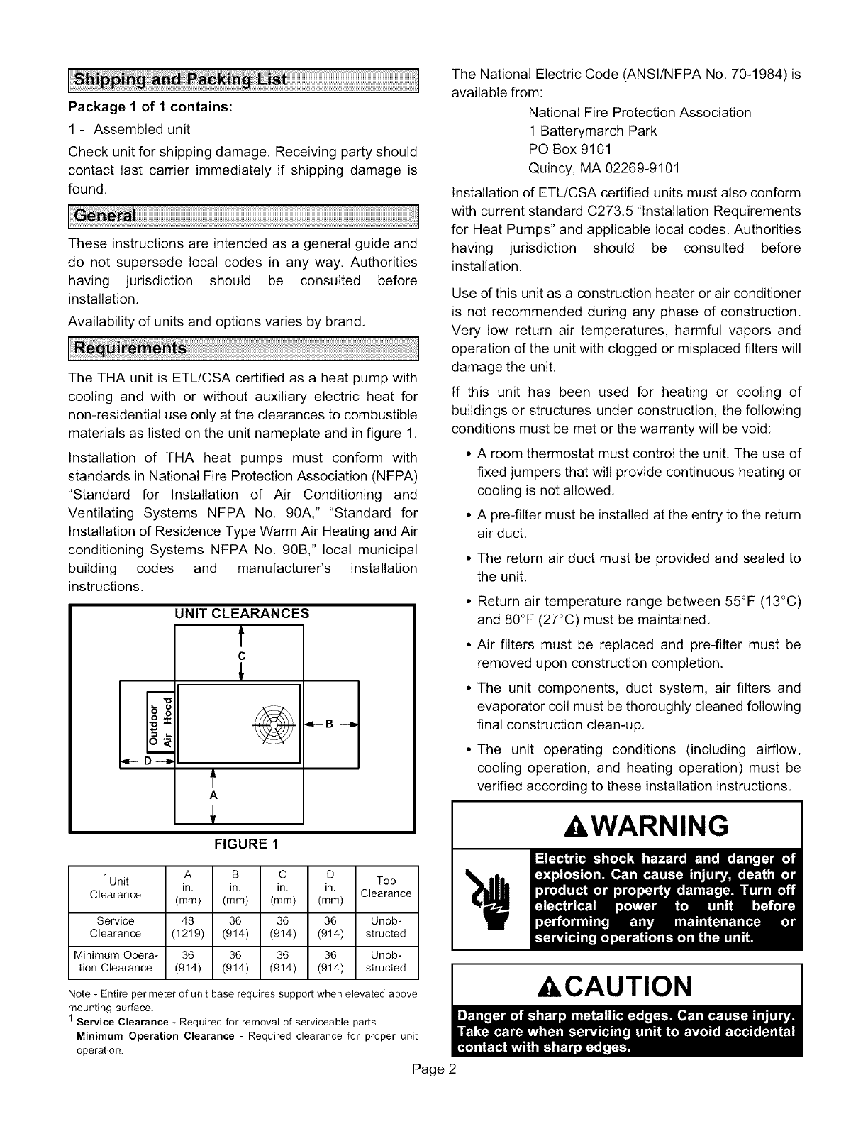
JNIT CLEARANCES
t
C
t
A
FIGURE 1
1 Unit A B C D
in. in. in. in. Top
Clearance (mm) (mm) (mm) (mm) Clearance
Service 48 36 36 36 Unob-
Clearance (1219) (914) (914) (914) structed
Minimum Opera- 36 36 36 36 Unob-
tion Clearance (914) (914) (914) (914) structed
Note - Entire perimeter of unit base requires support when elevated above
mounting surface.
1 Service Clearance - Required for removal of serviceable parts.
Minimum Operation Clearance - Required clearance for proper unit
operation.
Page 2
The National Electric Code (ANSI/NFPA No. 70-1984) is
available from:
National Fire Protection Association
1 Batterymarch Park
PO Box 9101
Quincy, MA 02269-9101
Installation of ETL/CSA certified units must also conform
with current standard C273.5 "Installation Requirements
for Heat Pumps" and applicable local codes. Authorities
having jurisdiction should be consulted before
installation.
Use of this unit as a construction heater or air conditioner
is not recommended during any phase of construction.
Very low return air temperatures, harmful vapors and
operation of the unit with clogged or misplaced filters will
damage the unit.
If this unit has been used for heating or cooling of
buildings or structures under construction, the following
conditions must be met or the warranty will be void:
• A room thermostat must control the unit. The use of
fixed jumpers that will provide continuous heating or
cooling is not allowed.
• A pre-filter must be installed at the entry to the return
air duct.
• The return air duct must be provided and sealed to
the unit.
• Return air temperature range between 55°F (13°C)
and 80°F (27°C) must be maintained.
• Air filters must be replaced and pre-filter must be
removed upon construction completion.
• The unit components, duct system, air filters and
evaporator coil must be thoroughly cleaned following
final construction clean-up.
• The unit operating conditions (including airflow,
cooling operation, and heating operation) must be
verified according to these installation instructions.
,WARNING
ACAUTION
klMPORTANT 2- Specified installation clearances must be
maintained when installing units, Refer to figure 1.
3- Top of support slab should be at least 4" (102mm)
above the finished grade and located so no run-off
water from higher ground can collect around the unit,
4- Units require support along all four sides of unit base.
Supports must be constructed of steel or suitably
treated wood materials,
NOTE -Securely fasten roof frame to roof per local codes.
A- Downflow Discharge Application
Roof Mounting with T1CURB
1- The T1CURB roof mounting frame must be installed,
flashed and sealed in accordance with the
instructions provided with the frame,
2- The TlCURB roof mounting frame should be square
and level to 1/16" per linear foot (5mm per linear
meter) in any direction,
3- Duct must be attached to the roof mounting frame
and not to the unit; supply and return plenums must
be installed before setting the unit,
Installer's Roof Mounting Frame
Many types of roof frames can be used to install the unit,
depending upon different roof structures. Items to keep in
mind when using the building frame or supports are:
1- The unit base is fully enclosed and insulated, so an
enclosed frame is not required.
2- The frames or supports must be constructed with
non-combustible materials and should be square
and level to 1/16" per linear foot (5mm per linear
meter) in any direction,
3- Frame or supports must be high enough to prevent
any form of moisture from entering unit.
Recommended minimum frame height is 14"
(356mm),
4- Duct must be attached to the roof mounting frame
and not to the unit. Supply and return plenums must
be installed before setting the unit,
5- Units require support along all four sides dunit base.
Supports must be constructed of steel or suitably
treated wood materials,
NOTE-When installing unit on a combustible surface for
downflow discharge applications, the TlCURB roof
mounting frame is required,
B - Horizontal Discharge Applications
1- Units which are equipped with an optional
economizer and installed in horizontal airflow
applications must use a horizontal conversion kit,
Page 3
All exterior ducts, joints, and openings in roof or building
walls must be insulated and weatherproofed with flashing
and sealing compounds in accordance with applicable
codes. Any duct passing through an unconditioned space
must be insulated.
CAUTION
1- Detach wooden base protection before rigging,
2- Remove all six base protection brackets before
setting unit, A 12" or longer extension is
recommended when using a drill gun.
3- Connect rigging to the unit base using both holes in
each corner. See figure 2,
4- All panels must be in place for rigging.
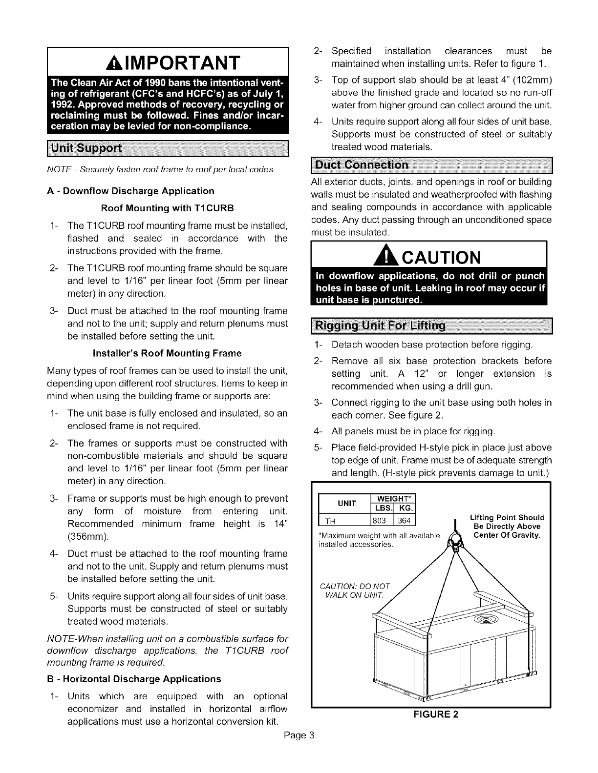
5- Place field-provided H-style pick in place just above
top edge dunit. Frame must be of adequate strength
and length. (H-style pick prevents damage to unit,
TH UNIT
*Maximum weight with all available
installed accessories.
Lifting Point Should
Be Directly Above
Center Of Gravity.
CAUTION: DO NOT
WALK ON UNIT.
FIGURE 2
Unit is shipped with panels covering the horizontal supply
and return air openings. Remove horizontal covers and
place over downflow openings for horizontal air
discharge, See figure 3, Secure in place with sheet metal
screws,
UNIT SUPPLY AND RETURN AIR OPENINGS
HORIZONTAL
HORIZONTAL SUPPLY AIR
RETURN AIR OPENING
OPENING __
DOWNFLOW DOWNFLOW
RETURN AIR SUPPLY AIR
OPENING OPENING
FIGURE 3
Units Equipped With An Optional Economizer -
1- Remove the horizontal supply air cover and position
over the downflow supply air opening, Secure with
sheet metal screws,
2- Leave the horizontal return air cover in place.
3- Locate the separately ordered horizontal air
discharge kit, Place the kit panel over the downflow
return air opening,
4- Remove and retain the barometric relief dampers and
lower hood.
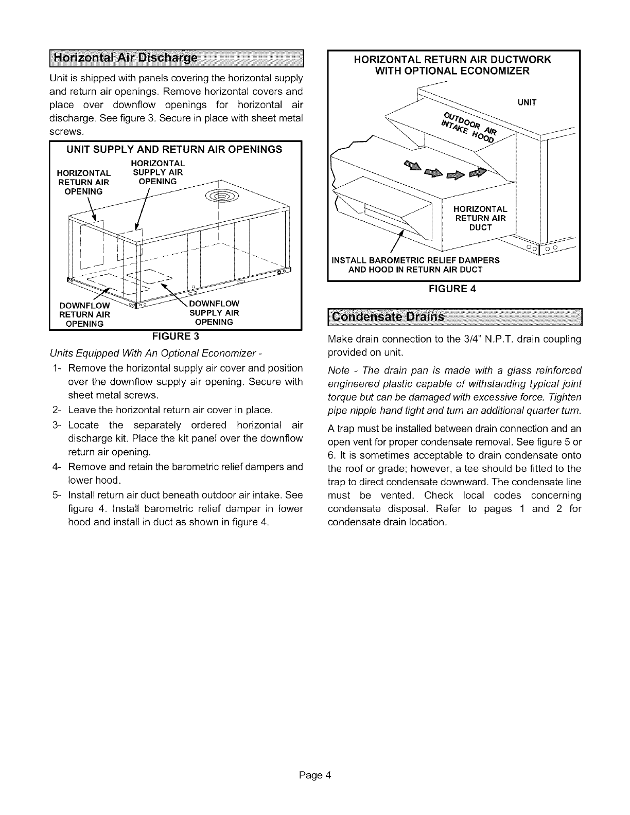
5- Install return air duct beneath outdoor air intake, See
figure 4. Install barometric relief damper in lower
hood and install in duct as shown in figure 4.
HORIZONTAL RETURN AIR DUCTWORK
WITH OPTIONAL ECONOMIZER
UNIT
HORIZONTAL
RETURN AIR
DUCT
INSTALL BAROMETRIC RELIEF DAMPERS
AND HOOD IN RETURN AIR DUCT
FIGURE 4
Make drain connection to the 3/4" N,P,T, drain coupling
provided on unit,
Note -The drain pan is made with a glass reinforced
engineered plastic capable of withstanding typical joint
torque but can be damaged with excessive force, Tighten
pipe nipple hand tight and turn an additional quarter turn,
A trap must be installed between drain connection and an
open vent for proper condensate removal, See figure 5 or
6, It is sometimes acceptable to drain condensate onto
the roof or grade; however, a tee should be fitted to the
trap to direct condensate downward. The condensate line
must be vented. Check local codes concerning
condensate disposal. Refer to pages 1 and 2 for
condensate drain location,
Page 4
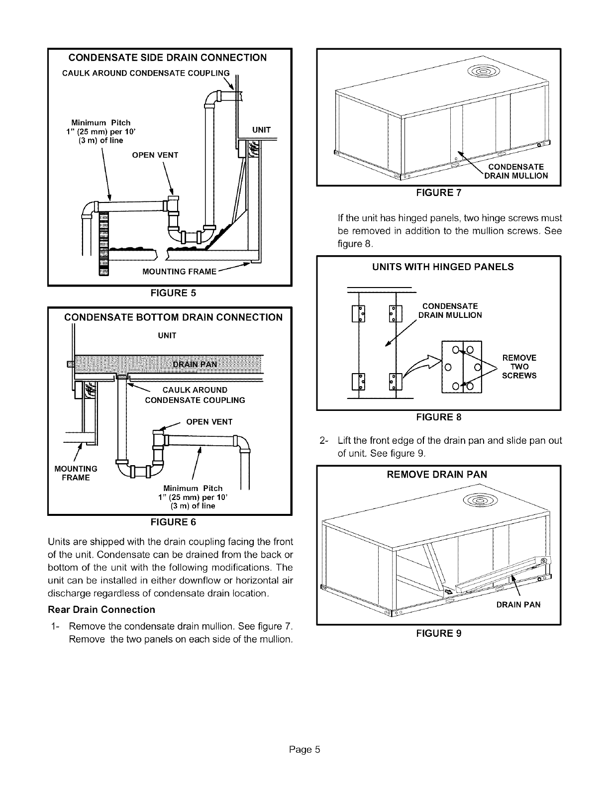
CONDENSATESIDEDRAIN CONNECTION
CAULK AROUND CONDENSATE COUPLING.
1Mi;i5mmU2) ;eitth0 'dX_ UN,T
(3re) of line OPENViNT I I _
\ II IIII
MOUNTING FRAME "_'P'_
FIGURE 5
CONDENSATE BOTTOM DRAIN CONNECTION
UNIT
CAULK AROUND
CONDENSATE COUPLING
MOUNTING
FRAME OPiN VENT
Minimum Pitch
1" (25 ram) per 10'
(3 m) of line
FIGURE 6
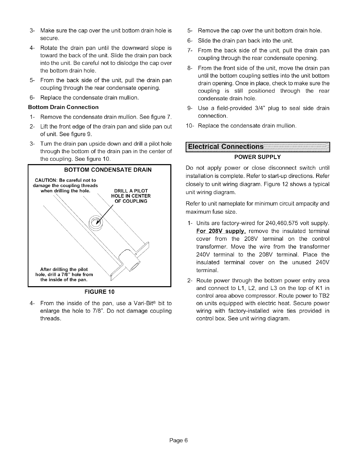
Units are shipped with the drain coupling facing the front
of the unit, Condensate can be drained from the back or
bottom of the unit with the following modifications. The
unit can be installed in either downflow or horizontal air
discharge regardless of condensate drain location.
Rear Drain Connection
1- Remove the condensate drain mullion, See figure 7.
Remove the two panels on each side of the mullion.
FIGURE 7
CONDENSATE
MULLION
If the unit has hinged panels, two hinge screws must
be removed in addition to the mullion screws. See
figure 8.
UNITS WITH HINGED PANELS
E,:I C°NDENSATE
DRAIN MULLION
E]
REMOVE
TWO
SCREWS
_
FIGURE 8
Lift the front edge of the drain pan and slide pan out
of unit, See figure 9.
REMOVE DRAIN PAN
DRAIN PAN
FIGURE 9
Page 5
_
4-
Make sure the cap over the unit bottom drain hole is
secure.
Rotate the drain pan until the downward slope is
toward the back of the unit. Slide the drain pan back
into the unit. Be careful not to dislodge the cap over
the bottom drain hole.
5- From the back side of the unit, pull the drain pan
coupling through the rear condensate opening.
6- Replace the condensate drain mullion.
Bottom Drain Connection
1- Remove the condensate drain mullion. See figure 7.
2- Lift the front edge of the drain pan and slide pan out
of unit. See figure 9.
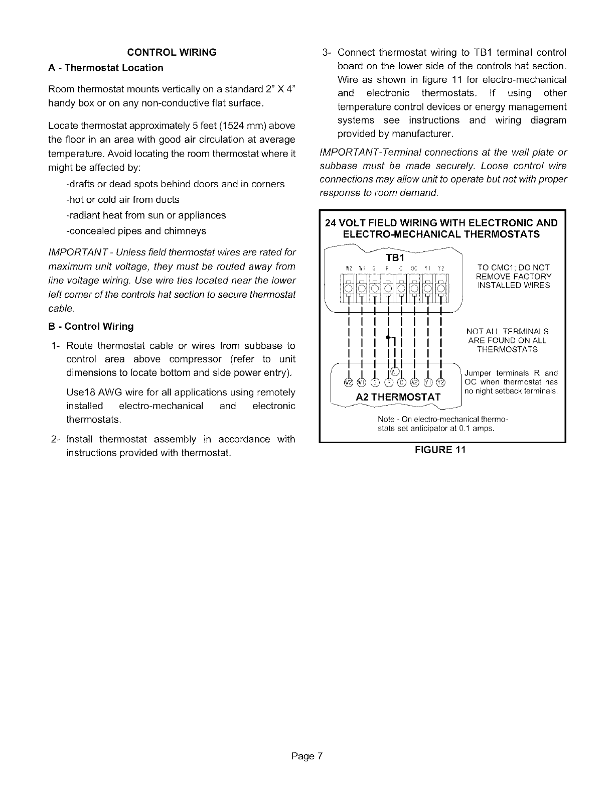
3- Turn the drain pan upside down and drill a pilot hole
through the bottom of the drain pan in the center of
the coupling. See figure 10.
BOTTOM CONDENSATE DRAIN
CAUTION: Be careful not to
damage the coupling threads
when drilling the hole. DRILL A PILOT
HOLE IN CENTER
OF COUPLING
.
After drilling the pilot
hole, drill a 7/8" hole from
the inside of the pan.
FIGURE 10
From the inside of the pan, use a Vari-BiP bit to
enlarge the hole to 7/8". Do not damage coupling
threads.
5- Remove the cap over the unit bottom drain hole,
6- Slide the drain pan back into the unit.
7- From the back side of the unit, pull the drain pan
coupling through the rear condensate opening,
8- From the front side of the unit, move the drain pan
until the bottom coupling settles into the unit bottom
drain opening. Once in place, check to make sure the
coupling is still positioned through the rear
condensate drain hole.
g- Use a field-provided 3/4" plug to seal side drain
connection.
10- Replace the condensate drain mullion.
POWER SUPPLY
Do not apply power or close disconnect switch until
installation is complete. Refer to start-up directions. Refer
closely to unit wiring diagram. Figure 12 shows a typical
unit wiring diagram.
Refer to unit nameplate for minimum circuit ampacity and
maximum fuse size.
-
-
Units are factory-wired for 240,460,575 volt supply.
For 208V supply, remove the insulated terminal
cover from the 208V terminal on the control
transformer. Move the wire from the transformer
240V terminal to the 208V terminal. Place the
insulated terminal cover on the unused 240V
terminal.
Route power through the bottom power entry area
and connect to L1, L2, and L3 on the top of K1 in
control area above compressor. Route power to TB2
on units equipped with electric heat. Secure power
wiring with factory-installed wire ties provided in
control box. See unit wiring diagram.
Page 6
CONTROLWIRING
A- Thermostat Location
Room thermostat mounts vertically on a standard 2" X 4"
handy box or on any non-conductive flat surface,
Locate thermostat approximately 5 feet (1524 mm) above
the floor in an area with good air circulation at average
temperature, Avoid locating the room thermostat where it
might be affected by:
-drafts or dead spots behind doors and in corners
-hot or cold air from ducts
-radiant heat from sun or appliances
-concealed pipes and chimneys
IMPORTANT -Unless field thermostat wires are rated for
maximum unit voltage, they must be routed away from
fine voltage wiring. Use wire ties located near the lower
left corner of the controls hat section to secure thermostat
cable.
B - Control Wiring
1- Route thermostat cable or wires from subbase to
control area above compressor (refer to unit
dimensions to locate bottom and side power entry),
Use18 AWG wire for all applications using remotely
installed electro-mechanical and electronic
thermostats,
2- Install thermostat assembly in accordance with
instructions provided with thermostat,
3- Connect thermostat wiring to TB1 terminal control
board on the lower side of the controls hat section,
Wire as shown in figure 11 for electro-mechanical
and electronic thermostats, If using other
temperature control devices or energy management
systems see instructions and wiring diagram
provided by manufacturer,
IMPORTANT-Terminal connections at the wall plate or
subbase must be made securely, Loose control wire
connections may allow unit to operate but not with proper
response to room demand.
24 VOLT FIELD WIRING WITH ELECTRONIC AND
ELECTRO-MECHANICAL THERMOSTATS
TO CMC1 ; DO NOT
REMOVE FACTORY
INSTALLED WIRES
IIIIIIII
I I I,hl I I I NOTALLTERMINALS
I I I I I I I AREFOUNDONALL
I I I III I I I THERMOSTATS
III IIIIII
"iii 1¢iiii JumperterminalsRand
w_ _) G_ R_ C_ A_ V_ V_ |OC when thermostat has
| no night setback terminals.
A2 THERMOSTAT /
Note - On electro-mechanical thermo-
stats set anticipator at 0.1 amps.
FIGURE 11
Page 7
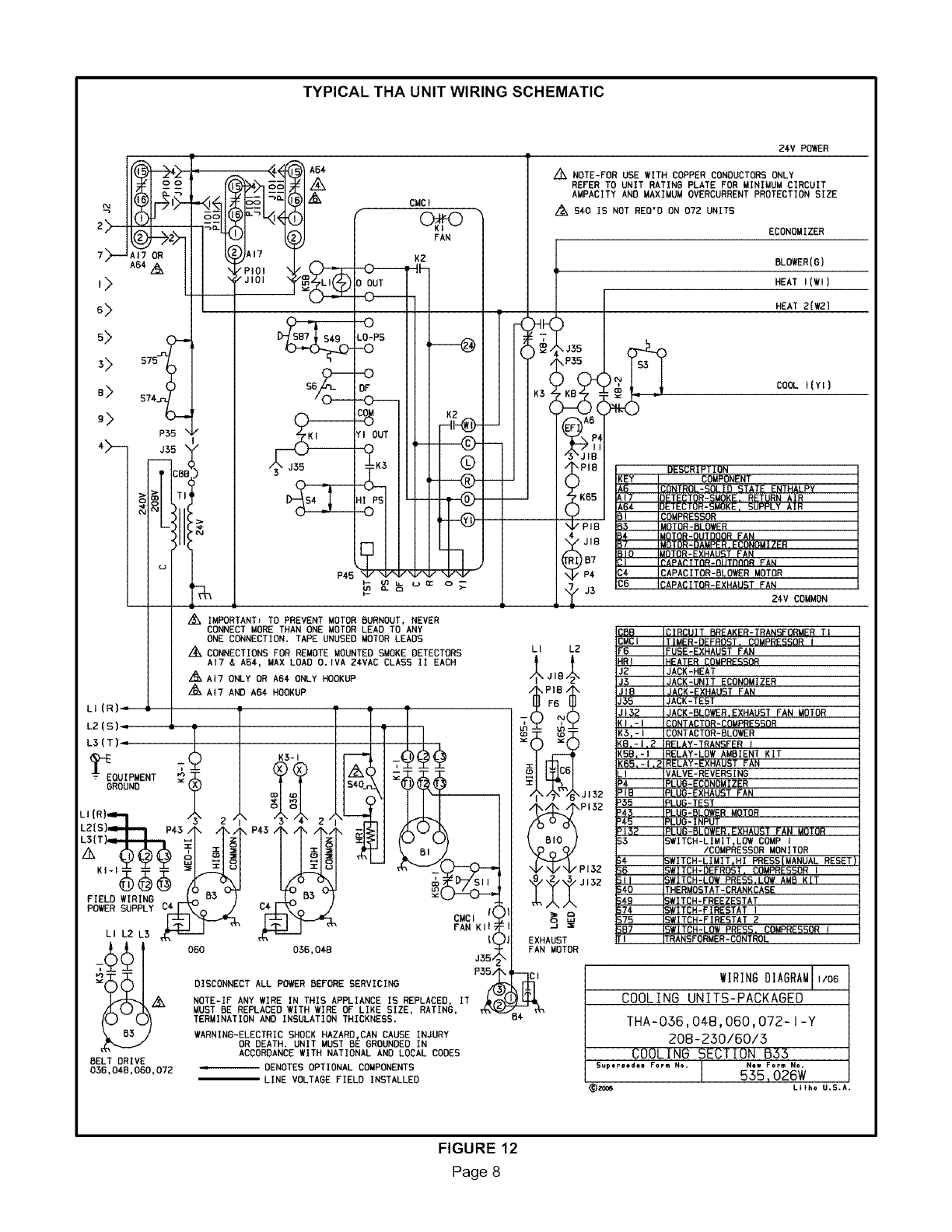
TYPICAL THA UNIT WIRING SCHEMATIC
DISCONNECT ALL POWER BEFORE SERVICING
NOTE-IF ANY WIRE IN THIS APPLIANCE IS REPLACEO, IT
MUST BE REPLACED WITH WIRE OF LIKE SIZE, RATING,
TERMINATION AND INSULATION THICKNESS.
WARNING-ELECTRIC SHOCK HAZARD,CAN CAUSE INJURY
OR DEATH. UNIT MUST BE GROUNDED IN
ACCORDANCE WITH NATIONAL AND LOCAL CODES
DENOTES OPTIONAL COMPONENTS
LINE VOLTAGE FIELD INSTALLED
24V POWER
/_ NOTE-FOR USE WITH COPPER CONDUCTORS ONLY
REFER TO UNIT RATING PLATE FOR MINIMUM CIRCUIT
AMPACITY AND MAXIMUa OVERCURRENT PROTECTION SIZE
./2',$40 IS NOT REO'D ON 072 UNITS
ECONOMIZER
)_ ;5
_5
•A6
\PIE
)
•K65
)
/PII
iJlt
)67
IP4
/J3
BLOIER(8)
HEAT I(!l)
HEAT 2(W2]
COOL I(YI)
DESCRIPTION
KEY COMPONENT
A6 CONTROL-SOLID STATE ENTHALPY
AI7 DETECTOR-SMOKE. RETURN AIR
A64 DETECTOR-SMOKE, SUPPLY AIR
81 COMPRESSOR
B3 MOTOR-BLOWER
B_ MOTOR-OUTDOOR FAN
67 MOTOR-DAMPER.ECONOMIZER
610 MOTOR-_XHAU_T FAN
CI _APA_ITOR-OIITDOOR FAN
CA CAPACITOR-BLOWER MOTOR
C6 CAPACITOR-EXHAUST FAN
24V COMMON
LI L2
\ J132
/_B_ PIS2
Pi3Z
EXHAUST
FAN MOTOR
CMCI lAMER-DEFROST, COMPRESSOR I
F6 =USE-EXHAUST FAN
HRI 4EATER _OMPRE_OR
J2 JACK-HEAT
J3 JACK-UNIT ECONOMIZER
JIB JACK-EXHAUST FAN
J35 JACK-TEST
3132 JACK-BLOWER,EXHAUST FAN MOTOR
KI,-I 30NTACTOR-COMPRESSOR
K3,-I _ONTACTOR-BLO_ER
K8.-I.2 RELAY-TRANSFER I
K58_-I RELAY-LOW AMBIENT KIT
K65,-I,_ RELAY-EXHAUST FAN
LI CALVE-REVERSING
P4 _LUO-ECONOMIZER
PIG _LUB-EXHAUST FAN
P35 _LUO-TEST
P43 _LUG-BLO@ER MOTOR
_45 _LUG-INPUT
P132 _LUG-BLOIER.EXHAUST FAN MOTOR
53 _WITCH-LIMIT,LOW COMP I
/COMPRESSOR MONITOR
$4 ;WITCH-LIMIT,HI PRESS|MANUAL RESET
SB ;WITCH-DEFROST. COMPRESSOR I
SII ;WITCH-LOW PRESS.LOW AMP KIT
S€0 FHERMOSTAT-CRANKCASE
_¢g ;WITCH-FREEZESTAT
$74 _ITCH-FIRESTAT I
S75 ;WITCH-FIRESTAT 2
SB7 _WITCH-LOW PRESS. COMPRESSOR I
TI PRANSFORMER-CONTROL
WIRINGDIAGRAMLL_
COOLING UNITS-PACKAGED
THA-036,04-8,060,072- I-Y
208-230/60/3
COOLING SECTION 633
Supersedes Form No. INet* Form No+
I535,026W
_) ZOO6 Lliho U,S,A,
FIGURE 12
Page 8
2 and2-1/2ton unitsareequippedwith directdrive
blowersonly.3,4,and5tonunitsareequippedwitheither
directdriveorbeltdriveblowers.060Sand072unitsare
availablewithbeltdriveblowersonly.
A, IMPORTANT
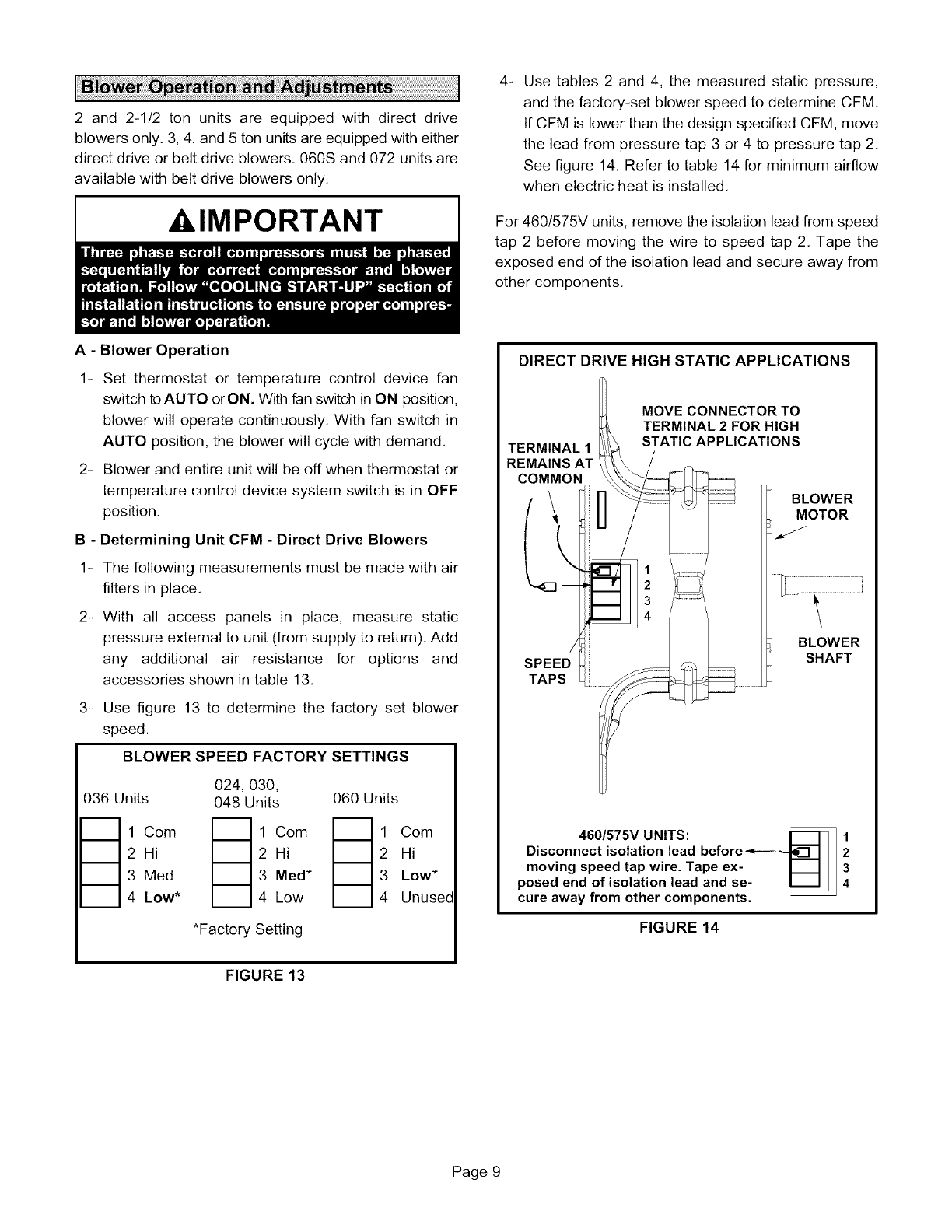
.Use tables 2 and 4, the measured static pressure,
and the factory-set blower speed to determine CFM
If CFM is lower than the design specified CFM, move
the lead from pressure tap 3 or 4 to pressure tap 2.
See figure 14. Refer to table 14 for minimum airflow
when electric heat is installed.
For 460/575V units, remove the isolation lead from speed
tap 2 before moving the wire to speed tap 2. Tape the
exposed end of the isolation lead and secure away from
other components.
A - Blower Operation
1- Set thermostat or temperature control device fan
switch to AUTO orON. With fan switch in ON position,
blower will operate continuously. With fan switch in
AUTO position, the blower will cycle with demand.
2- Blower and entire unit will be off when thermostat or
temperature control device system switch is in OFF
position.
B - Determining Unit CFM - Direct Drive Blowers
1- The following measurements must be made with air
filters in place.
2- With all access panels in place, measure static
pressure external to unit (from supply to return). Add
any additional air resistance for options and
accessories shown in table 13.
3- Use figure 13 to determine the factory set blower
speed.
BLOWER SPEED FACTORY SETTINGS
024, 030,
036 Units 048 Units 060 Units
_1Com _1Com _1Com
2 Hi 2 Hi 2 Hi
3 Med 3 Meal* 3 Low*
4 Low* 4 Low 4 Unused
*Factory Setting
DIRECT DRIVE HIGH STATIC APPLICATIONS
TERMINAL 1
REMAINS AT
COMMON
SPEED
TAPS
MOVE CONNECTOR TO
TERMINAL 2 FOR HIGH
STATIC APPLICATIONS
BLOWER
MOTOR
BLOWER
SHAFT
460/575V UNITS: [_
Disconnect isolation lead before _
moving speed tap wire. Tape ex-
posed end of isolation lead and se- I_1
cure away from other components.
FIGURE 14
1
2
3
4
FIGURE 13
Page 9

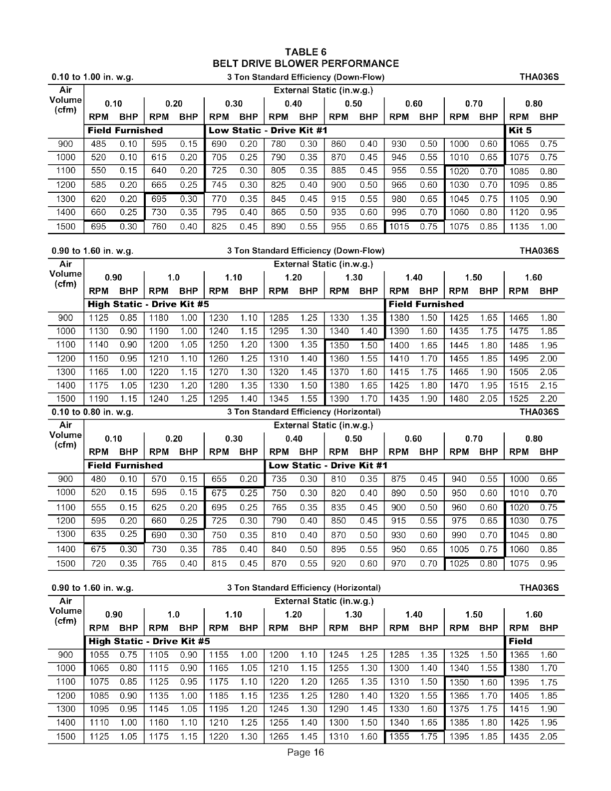
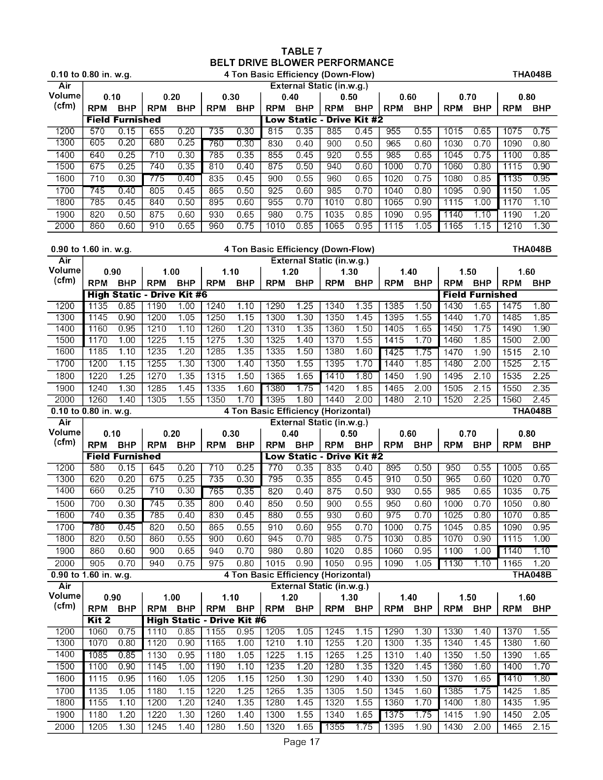
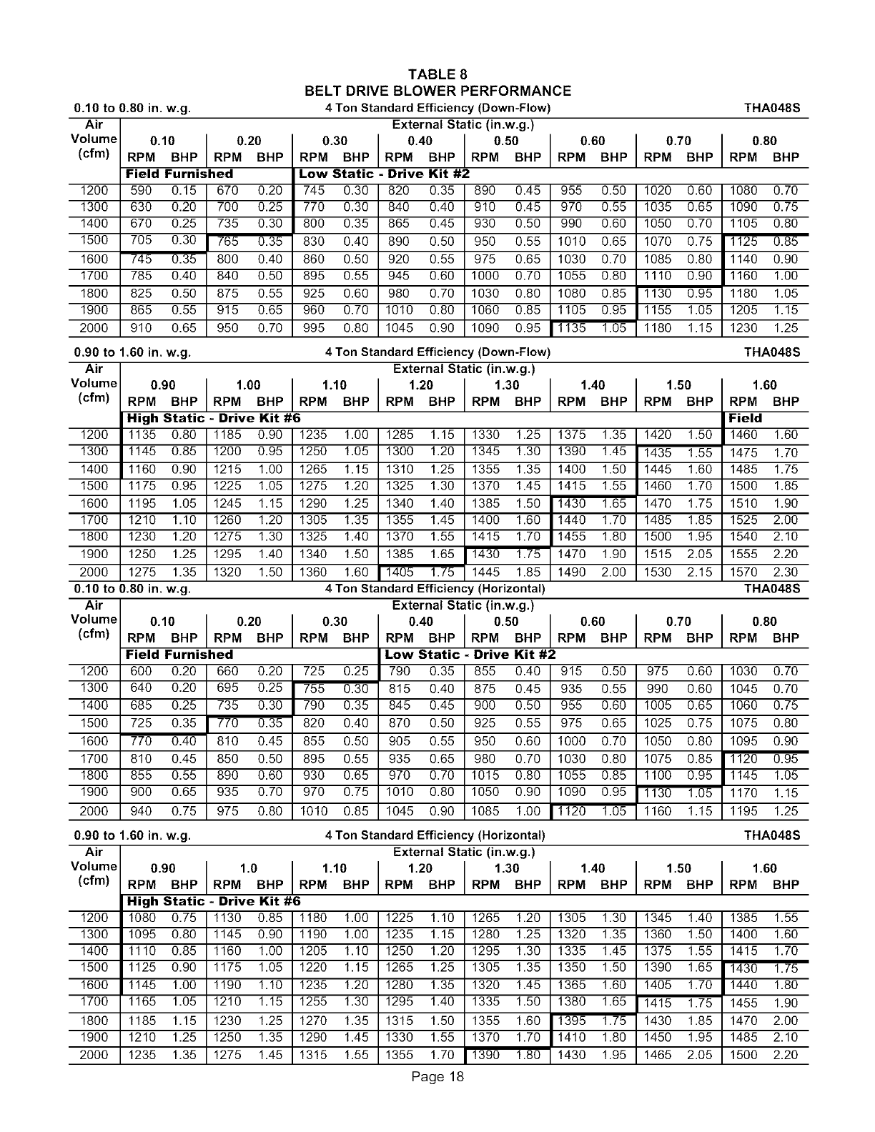
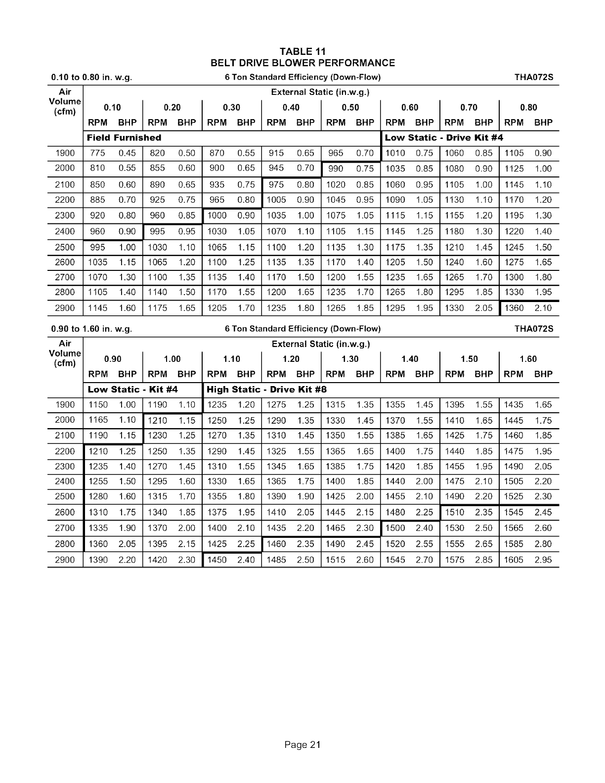
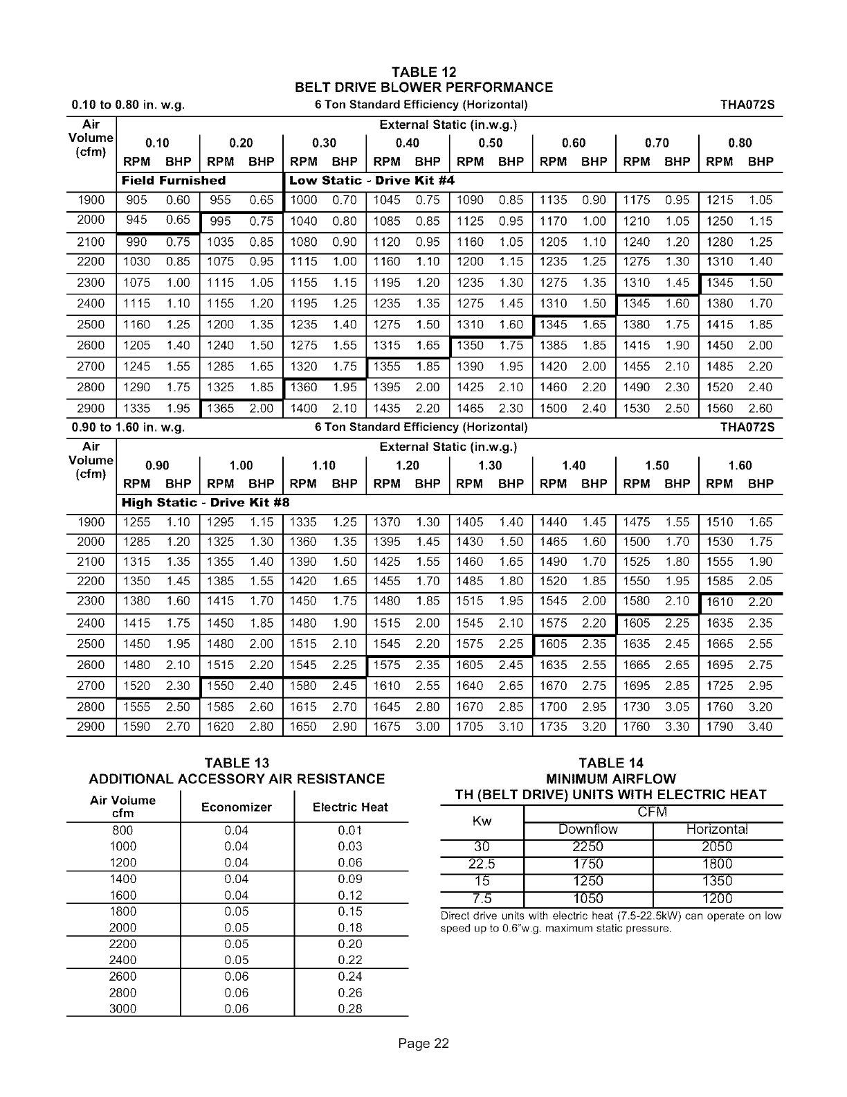
C- DeterminingUnitCFM- BeltDriveBlowers
1- Thefollowingmeasurementsmustbemadewithair
filtersinplace.
2- Withall accesspanelsin place,measurestatic
pressureexternaltounit(fromsupplytoreturn).
3- MeasuretheindoorblowerwheelRPM.
_Referring to tables 5 through 12, use static pressure
and RPM readings to determine unit CFM, Use table
13 when installing units with any of the options or
accessories listed, Refer to table 14 for minimum
airflow when electric heat is installed,
5- The blower RPM can be adjusted at the motor pulley,
Loosen Allen screw and turn adjustable pulley
clockwise to increase CFM. Turn counterclockwise to
decrease CFM See figure 16, Do not exceed
minimum and maximum number of pulley turns as
shown in table 1.
TABLE 1
MINIMUM AND MAXIMUM PULLEY ADJUSTMENT
t e,tt O'n.turn O enOaxi.turn O0entA Section No minimum 5
D - Blower Belt Adjustment
Maximum life and wear can be obtained from belts only if
proper pulley alignment and belt tension are maintained.
Tension new belts after a 24-48 hour period of operation.
This will allow belt to stretch and seat grooves. Make sure
blower and motor pulley are aligned as shown in figure 15,
PULLEY ALIGNMENT
ALIGNED
I
MOTOR BLOWER
PULLEY BELT PULLEY
NOT ALIGNED
FIGURE 15
1- Loosen four bolts securing motor base to mounting
frame. See figure 16,
2- To increase belt tension -
Slide blower motor downward to tighten the belt, This
increases the distance between the blower motor and
the blower housing,
To loosen belt tension -
Slide blower motor upward to loosen the belt, This
decreases the distance between the blower motor
and the blower housing,
3- Tighten four bolts securing motor base to the
mounting frame,
TO INCREASE CFM
LOOSEN ALLEN SCREW &
TURN PULLEY CLOCKWISE
TO DECREASE CFM
TURN PULLEY
COUNTERCLOCKWISE
BLOWER ASSEMBLY
SIDE VIEW
MOTOR _ALLEN
'-.. 7
LOOSEN ALLEN
SCREW TO
ADJUST CFM
TO INCREASE BELT TENSION
1-Loosen four bolts securing motor base to
mounting frame.
2-Slide the motor downward to tighter the belt.
3-Tighten four bolts on motor base.
LOOSEN FOUR BOLTS AND SLIDE
BLOWER MOTOR DOWNWARD TO
TIGHTEN BELT
FIGURE 16
Page 10
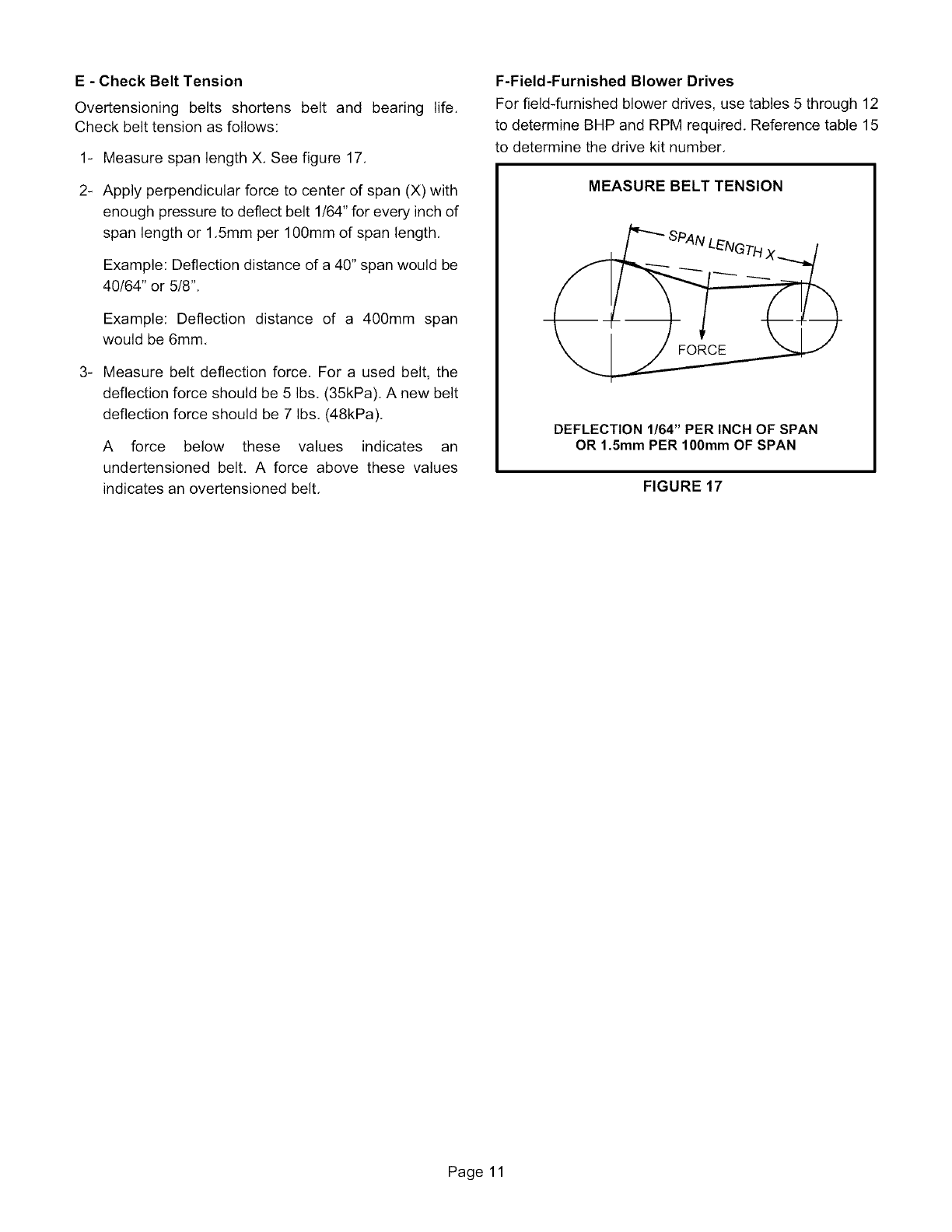
E - Check Belt Tension
Overtensioning belts shortens belt and bearing life.
Check belt tension as follows:
1- Measure span length X. See figure 17.
2- Apply perpendicular force to center of span (X) with
enough pressure to deflect belt 1/64" for every inch of
span length or 1.5mm per 100mm of span length.
Example: Deflection distance of a 40" span would be
40/64" or 5/8".
Example: Deflection distance of a 400mm span
would be 6mm.
3_ Measure belt deflection force. For a used belt, the
deflection force should be 5 Ibs. (35kPa). A new belt
deflection force should be 7 Ibs. (48kPa).
A force below these values indicates an
undertensioned belt. A force above these values
indicates an overtensioned belt.
F-Field-Furnished Blower Drives
For field-furnished blower drives, use tables 5 through 12
to determine BHP and RPM required. Reference table 15
to determine the drive kit number.
MEASURE BELT TENSION
DEFLECTION 1/64" PER INCH OF SPAN
OR 1.5mm PER 100mm OF SPAN
FIGURE 17
Page 11

TABLE 2
DIRECT DRIVE BLOWER PERFORMANCE
External Static Air Volume (cfm) at Various Blower Speeds
Pressure (in. 208 VOLTS 230 VOLTS
w.g.) High IMed,umILow H,gh IMed,umILow
2 and 2.5 Ton Standard Efficiency (Down-Flow) THA024S and THA030S
0.0 1230 975 845 1425 1125 910
0.1 1220 940 815 1395 1110 875
0.2 1205 910 775 1375 1085 845
0.3 1185 880 730 1350 1055 815
0.4 1155 845 680 1320 1010 780
0.5 1115 800 --- 1280 955 740
0.6 1060 750 --- 1225 895 690
0.7 985 685 --- 1150 830 ---
0.8 890 ...... 1050 755 ---
0.9 770 ...... 920 680 ---
1.0 ......... 760 ......
2 and 2.5 Ton Standard Efficiency (Horizontal) THA024S and THA030S
0.0 1165 925 800 1350 1065 865
0.1 1155 895 770 1325 1055 830
0.2 1140 865 735 1300 1030 800
0.3 1125 835 695 1280 1000 770
0.4 1095 800 645 1250 955 740
0.5 1055 760 -- 1215 905 700
0.6 1005 710 -- 1160 850 655
0.7 935 650 -- 1090 785 ---
0.8 845 ..... 995 720 ---
0.9 730 ..... 875 645 ---
1.0 ........ 720 ......
External Static Air Volume (cfm) at Various Blower Speeds
Pressure (in. 208 VOLTS 230 VOLTS 460/575 VOLTS
w.g.) High IMedium ILow High Medium ILow High IMedium ILow
3 and 4 Ton Basic Efficiency (Down-Flow) THA036B and THA048B
0.0 2025 1635 1145 2225 1845 1330 2125 1750 1220
0.1 1965 1605 1145 2140 1805 1325 2075 1715 1215
0.2 1910 1575 1135 2070 1770 1305 2025 1680 1205
0.3 1855 1545 1105 2010 1730 1275 1975 1640 1185
0.4 1800 1500 1055 1950 1680 1225 1915 1595 1155
0.5 1740 1445 995 1885 1620 1165 1850 1540 1105
0.6 1665 1370 910 1805 1540 1085 1770 1475 1040
0.7 1575 1280 810 1705 1440 990 1680 1400 950
0.8 1460 1165 --- 1580 1315 --- 1570 1310 ---
0.9 1325 1025 --- 1425 1155 --- 1445 1210 ---
1.0 1160 ...... 1230 ...... 1300 ......
3 and 4 Ton Basic Efficiency (Horizontal) THA036B and THA048B
0.0 1920 1560 1090 2110 1760 1265 2125 1770 1265
0.1 1855 1525 1090 2025 1715 1255 2055 1720 1245
0.2 1805 1490 1075 1955 1675 1235 1990 1675 1230
0.3 1755 1455 1045 1900 1635 1205 1930 1635 1210
0.4 1700 1415 1000 1840 1585 1165 1865 1590 1180
0.5 1640 1355 940 1775 1525 1100 1795 1535 1130
0.6 1560 1280 855 1690 1440 1020 1715 1465 1050
0.7 1455 1180 750 1580 1330 920 1620 1370 935
0.8 1325 1050 --- 1435 1180 --- 1500 1240 ---
0.9 1155 885 --- 1245 995 --- 1365 1075 ---
1.0 940 ...... 1000 ...... 1195 ......
Page 12
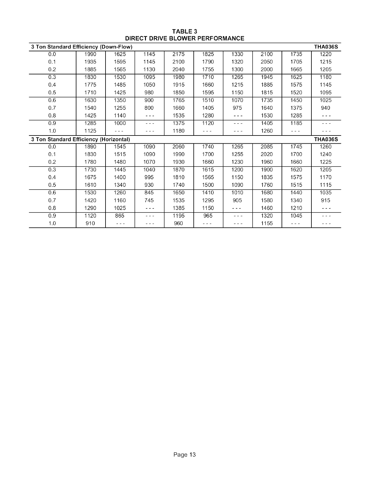
TABLE 3
DIRECT DRIVE BLOWER PERFORMANCE
3 Ton Standard Efficiency (Down-Flow) THA036S
0.0 1990 1625 1145 2175 1825 1330 2100 1735 1220
0.1 1935 1595 1145 2100 1790 1320 2050 1705 1215
0.2 1885 1565 1130 2040 1755 1300 2000 1665 1205
0.3 1830 1530 1095 1980 1710 1265 1945 1625 1180
0.4 1775 1485 1050 1915 1660 1215 1885 1575 1145
0.5 1710 1425 980 1850 1595 1150 1815 1520 1095
0.6 1630 1350 900 1765 1510 1070 1735 1450 1025
0.7 1540 1255 800 1660 1405 975 1640 1375 940
0.8 1425 1140 --- 1535 1280 --- 1530 1285 ---
0.9 1285 1000 --- 1375 1120 --- 1405 1185 ---
1.0 1125 ...... 1180 ...... 1260 ......
3 Ton Standard Efficiency (Horizontal) THA036S
0.0 1890 1545 1090 2060 1740 1265 2085 1745 1260
0.1 1830 1515 1090 1990 1700 1255 2020 1700 1240
0.2 1780 1480 1070 1930 1660 1230 1960 1660 1225
0.3 1730 1445 1040 1870 1615 1200 1900 1620 1205
0.4 1675 1400 995 1810 1565 1150 1835 1575 1170
0.5 1610 1340 930 1740 1500 1090 1760 1515 1115
0.6 1530 1260 845 1650 1410 1010 1680 1440 1035
0.7 1420 1160 745 1535 1295 905 1580 1340 915
0.8 1290 1025 --- 1385 1150 --- 1460 1210 ---
0.9 1120 865 --- 1195 965 --- 1320 1045 ---
1.0 910 ...... 960 ...... 1155 ......
Page 13
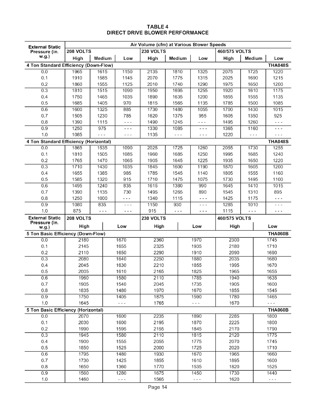
TABLE 4
DIRECT DRIVE BLOWER PERFORMANCE
External Static Air Volume (cfm) at Various Blower Speeds
Pressure (in. 208 VOLTS 230 VOLTS 460/575 VOLTS
w.g.) Hig.IMediumILow MediumILow I ed umILow
4 Ton Standard Efficiency (Down-Flow) THA048S
0.0 1965 1615 1150 2135 1810 1325 2075 1725 1220
0.1 1910 1585 1145 2070 1775 1315 2025 1690 1215
0.2 1860 1555 1125 2010 1740 1290 1975 1650 1200
0.3 1810 1515 1090 1950 1695 1255 1920 1610 1175
0.4 1750 1465 1035 1890 1635 1200 1855 1555 1135
0.5 1685 1405 970 1815 1565 1135 1785 1500 1085
0.6 1600 1325 885 1730 1480 1055 1700 1430 1015
0.7 1505 1230 785 1620 1375 955 1605 1350 925
0.8 1390 1115 --- 1490 1245 --- 1495 1260 ---
0.9 1250 975 --- 1330 1085 --- 1365 1160 ---
1.0 1085 ...... 1135 ...... 1220 ......
4 Ton Standard Efficiency (Horizontal) THA048S
0.0 1865 1535 1090 2025 1725 1260 2055 1730 1255
0.1 1810 1505 1085 1960 1685 1250 1995 1685 1240
0.2 1765 1470 1065 1905 1645 1225 1935 1650 1220
0.3 1710 1430 1035 1845 1600 1190 1870 1605 1200
0.4 1655 1385 985 1785 1545 1140 1805 1555 1160
0.5 1585 1320 915 1710 1475 1075 1730 1495 1100
0.6 1495 1240 835 1615 1380 990 1645 1410 1015
0.7 1390 1135 730 1495 1265 890 1545 1310 895
0.8 1250 1000 --- 1340 1115 --- 1425 1175 ---
0.9 1080 835 --- 1150 930 --- 1285 1010 ---
1.0 875 ...... 915 ...... 1115 ......
External Static 208 VOLTS 230 VOLTS 4601575 VOLTS
Pressure (in. HighILow High ILow High ILow
5 Ton Basic Efficiency (Down-Flow) THA060B
0.0 2180 1670 2360 1970 2300 1745
0.1 2145 1655 2325 1935 2180 1710
0.2 2110 1650 2290 1910 2090 1690
0.3 2080 1640 2250 1880 2035 1680
0.4 2045 1630 2210 1855 1995 1670
0.5 2005 1610 2165 1825 1965 1655
0.6 1960 1580 2110 1785 1940 1635
0.7 1905 1540 2045 1735 1905 1600
0.8 1835 1480 1970 1670 1855 1545
0.9 1750 1405 1875 1590 1780 1465
1.0 1645 --- 1765 --- 1670 ---
5 Ton Basic Efficiency (Horizontal) THA060B
0.0 2070 1600 2235 1890 2285 1800
0.1 2030 1600 2195 1870 2225 1800
0.2 1990 1595 2155 1845 2170 1790
0.3 1945 1580 2110 1815 2120 1775
0.4 1900 1555 2055 1775 2070 1745
0.5 1850 1525 2000 1725 2020 1710
0.6 1795 1480 1930 1670 1965 1660
0.7 1730 1425 1855 1610 1895 1600
0.8 1650 1360 1770 1535 1820 1525
0.9 1560 1280 1675 1450 1730 1440
1.0 1460 --- 1565 --- 1620 ---
Page 14

TABLE 5
BELT DRIVE BLOWER PERFORMANCE
0.10 to 0.80 in. w.g. 3 Ton Basic Efficiency (Down-Flow) THA036B
Air External Static (in.w.g.)
Volume 0.10 0.20 0.30 0.40 0.50 0.60 0.70
(cfm) RPM BHP RPM BHP RPM BHP RPM BHP RPM BHP RPM BHP RPM BHP
Field Furnished Low Static - Drive Kit #1
9OO
1000
1100
1200
1300
1400
1500
480 0.10
510 0.10
540 0.15
570 0.15
605 0.20
640 0.25
675 0.30
590 0.15
610 0.20
635 0.20
660 0.25
685 0.25
715 0.30
745 0.35
690 0.25
705 0.25
720 0.30
740 0.30
765 0.35
790 0.40
815 0.45
780 0.30
790 0.35
805 0.35
820 0.40
840 0.45
860 0.50
880 0.55
860 0.40
870 0.45
880 0.45
895 0.50
910 0.55
930 0.60
950 0.65
935 0.55
945 0.55
955 0.60
965 0.60
980 0.65
995 0.70
1010 0.75
1005 0.65
1010 0.65
1020 0.70
1030 0.75
1045 0.80
1055 0.85
1070 0.90
0.80
RPM BHP
Drive Kit
#5
1065 0.75
1075 9.80
1085 0.85
1095 9.85
1105 0.90
1115 9.95
1130 1.00
0.90 to 1.60 in. w.g.
Air
Volume
(cfm)
3 Ton Basic Efficiency (Down-Flow)
External Static (in.w.g.)
0.90 1.0 I1.10 1.20 1.30
RPM BHP RPM BHP IRPM BHP RPM BHP RPM BHP
High Static - Drive Kit #5
900 1125 0.90
1000 1135 0.90
1100 1145 0.95
1200 1155 1.00
1300 1165 1.05
1400 1175 1.10
1500 1185 1.15
0.10 to 0.80 in. w.g.
Air
Volume 0.10
THA036B
(cfm)
9OO
1000
1100
1200
1300
1400
1500
1185 1.00
1190 1.05
1200 1.10
1210 1.15
1220 1.20
1230 1.25
1240 1.30
1240 1.15
1245 1.20
1255 1.25
1265 1.30
1270 1.35
1280 1.40
1295 1.45
1290 1.30 1340 1.45
1300 1.35 1350 1.50
1305 1.40 1355 1.55
1315 1.45 1365 1.60
1325 1.50 1375 1.65
1335 1.55 1380 1.70
1345 1.60 1390 1.80
3Ton Basic Efficiency (Horizontal)
External Static (in.w.g.)
0.20 0.30
RPM BHP RPM BHP RPM BHP
Field Furnished
1.40
RPM BHP
Field Furnished
1390 1.60 1435 1.75
1395 1.65 1440 1.80
1405 1.70 1450 1.85
1410 1.75 1460 1.95
1420 1.80 1465 2.00
1430 1.90 1475 2.05
1440 1.95 1485 2.15
1.50 1.60
RPM BHP RPM BHP
1480 1.95
1485 1.95
1495 2.05
1505 2.10
1510 2.15
1520 2.25
1530 2.30
THA036B
0.40 0.50 0.60 0.70 0.80
RPM BHP RPM BHP RPM BHP RPM BHP RPM BHP
Low Static - Drive Kit #1
475 0.10
510 0.10
545 0.15
585 0.20
625 0.25
665 0.30
705 0.35
565 0.15
590 0.15
615 0.20
650 0.25
680 0.30
715 0.35
750 0.40
650 0.20
665 0.25
690 0.25
715 0.30
740 0.35
770 0.40
805 0.45
725 0.30
740 0.30
760 0.35
780 0.40
800 0.40
830 0.50
855 0.55
800 0.35
815 0.40
825 0.40
845 0.45
860 0.50
885 0.55
910 0.60
870 0.45
880 0.50
890 0.50
905 0.55
920 0.60
940 0.65
960 0.70
930 0.55
940 0.60
950 0.60
965 0.65
980 0.70
995 0.75
1010 0.80
990 0.65
1000 0.70
1010 0.75
1020 0.75
1030 0.80
1045 0.85
1065 0.90
0.90 to 1.60 in. w.g.
Air
Volume
(cfm)
9OO
1000
1100
1200
1300
1400
1500
3 Ton Basic Efficiency (Horizontal)
External Static (in.w.g.)
0.90 1.0 I1.10 1.20 1.30 1.40 1.50
RPM BHP RPM BHP IRPM BHP RPM BHP RPM BHP RPM BHP RPM BHP
High Static - Drive Kit #5
1045 0.75
1055 0.80
1065 0.85
1075 0.90
1085 0.90
1100 1.00
1115 1.05
1100 0.90
1105 0.90
1115 0.95
1125 1.00
1135 1.05
1150 1.10
1160 1.15
1150 1.00
1155 1.05
1165 1.10
1175 1.15
1185 1.20
1195 1.25
1210 1.30
1195 1.10
1205 1.15
1215 1.20
1220 1.25
1230 1.30
1240 1.35
1255 1.45
1240 1.25
1250 1.30
1260 1.35
1270 1.40
1275 1.45
1285 1.50
1295 1.55
1285 1.40
1295 1.45
1305 1.50
1310 1.55
1320 1.60
1330 1.65
1340 1.70
1325 1.50
1335 1.55
1345 1.60
1355 1.70
1365 1.75
1370 1.80
1380 1.85
THA036B
1.60
RPM BHP
Field
1365 1.65
1375 1.70
1385 1.75
1395 1.80
1405 1.90
1415 1.95
1420 2.00
Page 15
0.10 to 1.00 in. w.g.
Air
Volume 0.10
(cfm)
9OO
1000
1100
1200
1300
1400
1500
RPM BHP
Field Furnished
0.20
RPM BHP
TABLE 6
BELT DRIVE BLOWER PERFORMANCE
3 Ton Standard Efficiency (Down-Flow)
External Static (in.w.g.)
0.30 0.40 0.50 0.60 0.70
RPM BHP RPM BHP RPM BHP RPM BHP RPM BHP
Low Static - Drive Kit #1
THA036S
0.80
RPM BHP
Kit 5
485 0.10
520 0.10
550 0.15
585 0.20
620 0.20
660 0.25
695 0.30
595 0.15
615 0.20
640 0.20
665 0.25
695 0.30
730 0.35
760 0.40
690 0.20
705 0.25
725 0.30
745 0.30
770 0.35
795 0.40
825 0.45
780 0.30
790 0.35
805 0.35
825 0.40
845 0.45
865 0.50
890 0.55
860 0.40
870 0.45
885 0.45
900 0.50
915 0.55
935 0.60
955 0.65
930 0.50
945 0.55
955 0.55
965 0.60
980 0.65
995 0.70
1015 0.75
1000 0.60
1010 0.65
1020 0.70
1030 0.70
1045 0.75
1060 0.80
1075 0.85
1065 0.75
1075 0.75
1085 0.80
1095 0.85
1105 0.90
1120 0.95
1135 1.00
0.90 to 1.60 in. w.g.
Air
Volume
(cfm)
3 Ton Standard Efficiency (Down-Flow)
External Static (in.w.g.)
0.90 1.0 I 1.10 1.20 1.30
RPM BHP RPM BHP I RPM BHP RPM BHP RPM BHP
High Static -Drive Kit #5
900 1125 0.85
1000 1130 0.90
1100 1140 0.90
1200 1150 0.95
1300 1165 1.00
1400 1175 1.05
1500 1190 1.15
0.10 to 0.80 in. w.g.
Air
Volume
(cfm)
1180 1.00 1230 1.10
1190 1.00 1240 1.15
1200 1.05 1250 1.20
1210 1.10 1260 1.25
1220 1.15 1270 1.30
1230 1.20 1280 1.35
1240 1.25 1295 1.40
1285 1.25
1295 1.30
1300 1.35
1310 1.40
1320 1.45
1330 1.50
1345 1.55
1330 1.35
1340 1.40
1350 1.50
1360 1.55
1370 1.60
1380 1.65
1390 1.70
3 Ton Standard Efficiency (Horizontal)
External Static (in.w.g.)
THA036S
1.40
RPM BHP
Field Furnished
1380 1.50 1425 1.65
1390 1.60 1435 1.75
1400 1.65 1445 1.80
1410 1.70 1455 1.85
1415 1.75 1465 1.90
1425 1.80 1470 1.95
1435 1.90 1480 2.05
1.50 1.60
RPM BHP RPM BHP
1465 1.80
1475 1.85
1485 1.95
1495 2.00
1505 2.05
1515 2.15
1525 2.20
THA036S
0.10 0.20 0.30
RPM BHP RPM BHP RPM BHP
Field Furnished
0.40 0.50 0.60 0.70 0.80
RPM BHP RPM BHP RPM BHP RPM BHP RPM BHP
Low Static - Drive Kit #1
900 480 0.10
1000 520 0.15
1100 555 0.15
1200 595 0.20
1300 635 0.25
1400 675 0.30
1500 720 0.35
570 0.15
595 0.15
625 0.20
660 0.25
690 0.30
730 0.35
765 0.40
655 0.20
675 0.25
695 0.25
725 0.30
750 0.35
785 0.40
815 0.45
735 0.30
750 0.30
765 0.35
790 0.40
810 0.40
840 0.50
870 0.55
810 0.35
820 0.40
835 0.45
850 0.45
870 0.50
895 0.55
920 0.60
875 0.45
890 0.50
900 0.50
915 0.55
930 0.60
950 0.65
970 0.70
940 0.55
950 0.60
960 0.60
975 0.65
990 0.70
1005 0.75
1025 0.80
1000 0.65
1010 0.70
1020 0.75
1030 0.75
1045 0.80
1060 0.85
1075 0.95
0.90 to 1.60 in. w.g.
Air
Volume
(cfm)
9OO
1000
1100
1200
1300
1400
1500
3 Ton Standard Efficiency (Horizontal)
External Static (in.w.g.)
0.90 1.0 I 1.10 1.20 1.30 1.40 1.50
RPM BHP RPM BHP I RPM BHP RPM BHP
High Static -Drive Kit #5
1055 0.75
1065 0.80
1075 0.85
1085 0.90
1095 0.95
1110 1.00
1125 1.05
RPM BHP RPM BHP RPM BHP
THA036S
1105 0.90
1115 0.90
1125 0.95
1135 1.00
1145 1.05
1160 1.10
1175 1.15
1155 1.00
1165 1.05
1175 1.10
1185 1.15
1195 1.20
1210 1.25
1220 1.30
1200 1.10
1210 1.15
1220 1.20
1235 1.25
1245 1.30
1255 1.40
1265 1.45
Page 16
1245 1.25
1255 1.30
1265 1.35
1280 1.40
1290 1.45
1300 1.50
1310 1.60
1285 1.35
1300 1.40
1310 1.50
1320 1.55
1330 1.60
1340 1.65
1355 1.75
1325 1.50
1340 1.55
1350 1.60
1365 1.70
1375 1.75
1385 1.80
1395 1.85
1.60
RPM BHP
Field
1365 1.60
1380 1.70
1395 1.75
1405 1.85
1415 1.90
1425 1.95
1435 2.05
0.10to 0.80 in. w.g.
Air
Volume
(cfm)
1200
1300
1400
1500
1600
1700
1800
1900
2000
TABLE 7
BELT DRIVE BLOWER PERFORMANCE
4 Ton Basic Efficiency (Down-Flow) THA048B
External Static (in.w.g.)
0.10 0.20 0.30 0.40 0.50 0.60 0.70 0.80
RPM BHP RPM BHP RPM BHP RPM BHP RPM BHP RPM BHP RPM BHP RPM BHP
Field Furnished
570 0.15
605 0.20
640 0.25
675 0.25
710 0.30
745 0.40
785 0.45
820 0.50
860 0.60
655 0.20
680 0.25
710 0.30
740 0.35
775 0.40
805 0.45
840 0.50
875 0.60
910 0.65
735 0.30
760 0.30
785 0.35
810 0.40
835 0.45
865 0.50
895 0.60
930 0.65
960 0.75
Low Static - Drive Kit #2
815 0.35
830 0.40
855 0.45
875 0.50
900 0.55
925 0.60
955 0.70
980 0.75
1010 0.85
885 0.45 955 0.55
900 0.50 965 0.60
920 0.55 985 0.65
940 0.60 1000 0.70
960 0.65 1020 0.75
985 0.70 1040 0.80
1010 0.80 1065 0.90
1035 0.85 1090 0.95
1065 0.95 1115 1.05
1015 0.65
1030 0.70
1045 0.75
1060 0.80
1080 0.85
1095 0.90
1115 1.00
1140 1.10
1165 1.15
1075 0.75
1090 0.80
1100 0.85
1115 0.90
1135 0.95
1150 1.05
1170 1.10
1190 1.20
1210 1.30
0.90 to 1.60 in. w.g. 4 Ton Basic Efficiency (Down-Flow)
Air External Static (in.w.g.)
Volume 0.90 1.00 I1.10 1.20 1.30 1.40
(cfm) RPM BHP RPM BHP IRPM BHP RPM BHP RPM BHP RPM BHP
High Static - Drive Kit #6
1200 1135 0.85
1300 1145 0.90
1400 1160 0.95
1500 1170 1.00
1600 1185 1.10
1700 1200 1.15
1800 1220 1.25
1900 1240 1.30
2000 1260 1.40
0.10 to 0.80 in. w.g.
Air
Volume
(cfm)
THA048B
1.50 1.60
RPM BHP RPM BHP
1190 1.00 1240 1.10
1200 1.05 1250 1.15
1210 1.10 1260 1.20
1225 1.15 1275 1.30
1235 1.20 1285 1.35
1255 1.30 1300 1.40
1270 1.35 1315 1.50
1285 1.45 1335 1.60
1305 1.55 1350 1.70
1290 1.25
1300 1.30
1310 1.35
1325 1.40
1335 1.50
1350 1.55
1365 1.65
1380 1.75
1395 1.80
1340 1.35
1350 1.45
1360 1.50
1370 1.55
1380 1.60
1395 1.70
1410 1.80
1420 1.85
1440 2.00
1385 1.50
1395 1.55
1405 1.65
1415 1.70
1425 1.75
1440 1.85
1450 1.90
1465 2.00
1480 2.10
Field Furnished
1430 1.65 1475 1.80
1440 1.70 1485 1.85
1450 1.75 1490 1.90
1460 1.85 1500 2.00
1470 1.90 1515 2.10
1480 2.00 1525 2.15
1495 2.10 1535 2.25
1505 2.15 1550 2.35
1520 2.25 1560 2.45
4 Ton Basic Efficiency (Horizontal) THA048B
External Static (in.w.g.)
0.10 0.20 0.30 0.40 0.50 0.60 0.70 0.80
RPM BHP RPM BHP RPM BHP RPM BHP RPM BHP RPM BHP RPM BHP RPM BHP
Field Furnished Low Static - Drive Kit #2
1200 580 0.15
1300 620 0.20
1400 660 0.25
1500 700 0.30
1600 740 0.35
1700 780 0.45
1800 820 0.50
1900 860 0.60
2000 905 0.70
0.90 to 1.60 in. w.g.
Air
Volume 0.90
(cfm) RPM BHP
Kit 2
1200 1060 0.75
1300 1070 0.80
1400 1085 0.85
1500 1100 0.90
1600 1115 0.95
1700 1135 1.05
1800 1155 1.10
1900 1180 1.20
2000 1205 1.30
645 0.20
675 0.25
710 0.30
745 0.35
785 0.40
820 0.50
860 0.55
900 0.65
940 0.75
710 0.25
735 0.30
765 0.35
800 0.40
830 0.45
865 0.55
900 0.60
940 0.70
975 0.80
770 0.35 835 0.40
795 0.35 855 0.45
820 0.40 875 0.50
850 0.50 900 0.55
880 0.55 930 0.60
910 0.60 955 0.70
945 0.70 985 0.75
980 0.80 1020 0.85
1015 0.90 1050 0.95
895 0.50
910 0.50
930 0.55
950 0.60
975 0.70
1000 0.75
1030 0.85
1060 0.95
1090 1.05
950 0.55
965 0.60
985 0.65
1000 0.70
1025 0.80
1045 0.85
1070 0.90
1100 1.00
1130 1.10
1005 0.65
1020 0.70
1035 0.75
1050 0.80
1070 0.85
1090 0.95
1115 1.00
1140 1.10
1165 1.20
THA048B
4 Ton Basic Efficiency (Horizontal)
External Static (in.w.g.)
1.00 I1.10 1.20 1.30 1.40 1.50 1.60
RPM BHP IRPM BHP RPM BHP RPM BHP RPM BHP RPM BHP RPM BHP
High Static - Drive Kit #6
1110 0.85
1120 0.90
1130 0.95
1145 1.00
1160 1.05
1180 1.15
1200 1.20
1220 1.30
1245 1.40
1155 0.95
1165 1.00
1180 1.05
1190 1.10
1205 1.15
1220 1.25
1240 1.35
1260 1.40
1280 1.50
1205 1.05
1210 1.10
1225 1.15
1235 1.20
1250 1.30
1265 1.35
1280 1.45
1300 1.55
1320 1.65
Page 17
1245 1.15
1255 1.20
1265 1.25
1280 1.35
1290 1.40
1305 1.50
1320 1.55
1340 1.65
1355 1.75
1290 1.30
1300 1.35
1310 1.40
1320 1.45
1330 1.50
1345 1.60
1360 1.70
1375 1.75
1395 1.90
1330 1.40
1340 1.45
1350 1.50
1360 1.60
1370 1.65
1385 1.75
1400 1.80
1415 1.90
1430 2.00
1370 1.55
1380 1.60
1390 1.65
1400 1.70
1410 1.80
1425 1.85
1435 1.95
1450 2.05
1465 2.15
0.10to 0.80 in. w.g.
Air
Volume
(cfm)
1200
1300
1400
1500
1600
1700
1800
1900
2000
0.10 0.20
RPM BHP RPM BHP
Field Furnished
TABLE 8
BELT DRIVE BLOWER PERFORMANCE
4 Ton Standard Efficiency (Down-Flow) THA048S
External Static (in.w.g.)
0.30 0.40 0.50 0.60 0.70 0.80
RPM BHP RPM BHP RPM BHP RPM BHP RPM BHP RPM BHP
Low Static - Drive Kit #2
590 0.15
630 0.20
670 0.25
705 0.30
745 0.35
785 0.40
825 0.50
865 0.55
910 0.65
670 0.20
700 0.25
735 0.30
765 0.35
800 0.40
840 0.50
875 0.55
915 0.65
950 0.70
745 0.30
770 0.30
800 0.35
830 0.40
860 0.50
895 0.55
925 0.60
960 0.70
995 0.80
820 0.35
840 0.40
865 0.45
890 0.50
920 0.55
945 0.60
980 0.70
1010 0.80
1045 0.90
890 0.45
910 0.45
930 0.50
950 0.55
975 0.65
1000 0.70
1030 0.80
1060 0.85
1090 0.95
955 0.50
970 0.55
990 0.60
1010 0.65
1030 0.70
1055 0.80
1080 0.85
1105 0.95
1135 1.05
1020 0.60
1035 0.65
1050 0.70
1070 0.75
1085 0.80
1110 0.90
1130 0.95
1155 1.05
1180 1.15
1080 0.70
1090 0.75
1105 0.80
1125 0.85
1140 0.90
1160 1.00
1180 1.05
1205 1.15
1230 1.25
0.90 to 1.60 in. w.g.
Air
Volume
(cfm)
1200
1300
1400
1500
1600
1700
1800
1900
2000
4 Ton Standard Efficiency (Down-Flow)
External Static (in.w.g.)
0.90 1.00 I1.10 1.20 1.30 1.40 1.50
RPM BHP RPM BHP IRPM BHP RPM BHP RPM BHP RPM BHP RPM BHP
High Static -Drive Kit #6
1135 0.80
1145 0.85
1160 0.90
1175 0.95
1195 1.05
1210 1.10
1230 1.20
1250 1.25
1275 1.35
THA048S
1.60
RPM BHP
1185 0.90 1235 1.00
1200 0.95 1250 1.05
1215 1.00 1265 1.15
1225 1.05 1275 1.20
1245 1.15 1290 1.25
1260 1.20 1305 1.35
1275 1.30 1325 1.40
1295 1.40 1340 1.50
1320 1.50 1360 1.60
1285 1.15
1300 1.20
1310 1.25
1325 1.30
1340 1.40
1355 1.45
1370 1.55
1385 1.65
1405 1.75
1330 1.25
1345 1.30
1355 1.35
1370 1.45
1385 1.50
1400 1.60
1415 1.70
1430 1.75
1445 1.85
1375 1.35
1390 1.45
1400 1.50
1415 1.55
1430 1.65
1440 1.70
1455 1.80
1470 1.90
1490 2.00
1420 1.50
1435 1.55
1445 1.60
1460 1.70
1470 1.75
1485 1.85
1500 1.95
1515 2.05
1530 2.15
Field
1460 1.60
1475 1.70
1485 1.75
1500 1.85
1510 1.90
1525 2.00
1540 2.10
1555 2.20
1570 2.30
0.10 to 0.80 in. w.g.
Air
Volume
(cfm)
4 Ton Standard Efficiency (Horizontal) THA048S
External Static (in.w.g.)
0.10 0.20 0.30 0.40 0.50 0.60 0.70 0.80
RPM BHP RPM BHP RPM BHP RPM BHP RPM BHP RPM BHP RPM BHP RPM BHP
Field Furnished Low Static - Drive Kit #2
1200
1300
1400
1500
1600
1700
1800
1900
2000
0.90 to 1.60 in. w.g.
600 0.20
640 0.20
685 0.25
725 0.35
770 0.40
810 0.45
855 0.55
900 0.65
940 0.75
660 0.20
695 0.25
735 0.30
770 0.35
810 0.45
850 0.50
890 0.60
935 0.70
975 0.80
725 0.25
755 0.30
790 0.35
820 0.40
855 0.50
895 0.55
930 0.65
970 0.75
1010 0.85
790 0.35 855 0.40
815 0.40 875 0.45
845 0.45 900 0.50
870 0.50 925 0.55
905 0.55 950 0.60
935 0.65 980 0.70
970 0.70 1015 0.80
1010 0.80 1050 0.90
1045 0.90 1085 1.00
4 Ton Standard Efficiency (Horizontal)
915 0.50
935 0.55
955 0.60
975 0.65
1000 0.70
1030 0.80
1055 0.85
1090 0.95
1120 1.05
975 0.60
990 0.60
1005 0.65
1025 0.75
1050 0.80
1075 0.85
1100 0.95
1130 1.05
1160 1.15
1030 0.70
1045 0.70
1060 0.75
1075 0.80
1095 0.90
1120 0.95
1145 1.05
1170 1.15
1195 1.25
THA048S
Air
Volume
(cfm)
1200
1300
1400
1500
1600
1700
1800
1900
2000
External Static (in.w.g.)
0.90 1.0 I1.10 1.20 1.30 1.40 1.50 1.60
RPM BHP RPM BHP IRPM BHP RPM BHP RPM BHP RPM BHP RPM BHP RPM BHP
High Static -Drive Kit #6
1080 0.75
1095 0.80
1110 0.85
1125 0.90
1145 1.00
1165 1.05
1185 1.15
1210 1.25
1235 1.35
1130 0.85
1145 0.90
1160 1.00
1175 1.05
1190 1.10
1210 1.15
1230 1.25
1250 1.35
1275 1.45
1180 1.00
1190 1.00
1205 1.10
1220 1.15
1235 1.20
1255 1.30
1270 1.35
1290 1.45
1315 1.55
1225 1.10
1235 1.15
1250 1.20
1265 1.25
1280 1.35
1295 1.40
1315 1.50
1330 1.55
1355 1.70
Page 18
1265 1.20
1280 1.25
1295 1.30
1305 1.35
1320 1.45
1335 1.50
1355 1.60
1370 1.70
1390 1.80
1305 1.30
1320 1.35
1335 1.45
1350 1.50
1365 1.60
1380 1.65
1395 1.75
1410 1.80
1430 1.95
1345 1.40
1360 1.50
1375 1.55
1390 1.65
1405 1.70
1415 1.75
1430 1.85
1450 1.95
1465 2.05
1385 1.55
1400 1.60
1415 1.70
1430 1.75
1440 1.80
1455 1.90
1470 2.00
1485 2.10
1500 2.20

0.10to 0.80 in. w.g.
Air
Volume
(cfm)
1600
1700
1800
1900
2000
2100
2200
2300
2400
TABLE 9
BELT DRIVE BLOWER PERFORMANCE
5 Ton Basic Efficiency (Down-Flow) THA060B
External Static (in.w.g.)
0.10 0.20 0.30 0.40 0.50 0.60 0.70 0.80
RPM BHP RPM BHP RPM BHP RPM BHP RPM BHP RPM BHP RPM BHP RPM BHP
Field Furnished
705 0.30
740 0.35
780 0.40
815 0.50
855 0.55
890 0.65
930 0.70
970 0.80
1005 0.90
765 0.35
800 0.40
835 0.50
870 0.55
905 0.60
940 0.70
975 0.80
1010 0.90
1050 1.00
825 0.40
855 0.50
885 0.55
920 0.60
950 0.70
985 0.80
1020 0.85
1055 0.95
1090 1.10
Low Static - Drive Kit #3
880 0.50
910 0.55
940 0.60
970 0.70
1000 0.75
1030 0.85
1065 0.95
1095 1.05
1130 1.15
935 0.55 990 0.60
960 0.60 1010 0.70
990 0.70 1035 0.75
1015 0.75 1065 0.85
1045 0.85 1090 0.90
1075 0.95 1120 1.00
1105 1.05 1145 1.10
1135 1.15 1175 1.20
1170 1.25 1210 1.35
1040 0.70
1060 0.75
1085 0.85
1110 0.90
1135 1.00
1160 1.10
1190 1.20
1215 1.30
1245 1.45
1090 0.75
1110 0.85
1130 0.90
1155 1.00
1180 1.10
1205 1.20
1230 1.30
1255 1.40
1285 1.55
0.90 to 1.60 in. w.g. 5 Ton Basic Efficiency (Down-Flow) THA060B
Air External Static (in.w.g.)
Volume 1.10 1.20 1.30 1.40 1.50 1.60
(cfm) RPM BHP RPM BHP RPM BHP RPM BHP RPM BHP RPM BHP
High Static - Drive Kit #7
1600
1700
1800
1900
2000
2100
2200
2300
2400
0.90 1.00
RPM BHP RPM BHP
Low Static - Drive Kit
#3
1135 0.85
1155 0.90
1175 1.00
1200 1.10
1220 1.15
1245 1.25
1270 1.40
1295 1.50
1320 1.60
1185 0.95
1200 1.00
1220 1.10
1240 1.15
1260 1.25
1285 1.35
1310 1.50
1335 1.60
1360 1.70
1230 1.00
1245 1.10
1265 1.15
1280 1.25
1300 1.35
1325 1.45
1345 1.55
1370 1.70
1395 1.80
1275 1.10
1290 1.20
1305 1.25
1325 1.35
1340 1.45
1360 1.55
1385 1.65
1405 1.80
1430 1.90
1315 1.20
1330 1.30
1345 1.35
1365 1.45
1380 1.55
1400 1.65
1420 1.75
1445 1.90
1465 2.05
1355 1.30
1370 1.35
1385 1.45
1400 1.55
1420 1.65
1440 1.75
1460 1.90
1480 2.00
1500 2.15
1400 1.40
1410 1.45
1425 1.55
1440 1.65
1455 1.75
1475 1.85
1495 2.00
1515 2.10
1535 2.25
1440 1.50
1450 1.60
1465 1.65
1480 1.75
1495 1.85
1510 1.95
1530 2.10
1550 2.20
1570 2.35
0.10 to 0.80 in. w.g. 5 Ton Basic Efficiency (Horizontal) THA060B
Air External Static (in.w.g.)
Volume 0.10 0.20 0.30 0.40 0.50 0.60 0.70 0.80
(cfm) RPM BHP RPM BHP RPM BHP RPM BHP RPM BHP RPM BHP RPM BHP RPM BHP
Low Static - Drive Kit #3
1600
1700
1800
1900
2000
2100
2200
2300
2400
0.90 to 1.60 in. w.g.
Field Furnished
735 0.35
775 0.40
815 0.50
855 0.55
895 0.65
940 0.75
980 0.85
1020 0.95
1065 1.10
780 0.40
815 0.45
855 0.55
895 0.60
935 0.70
970 0.80
1010 0.90
1050 1.00
1095 1.15
825 0.45
860 0.50
895 0.60
935 0.65
970 0.75
1005 0.85
1045 0.95
1085 1.10
1125 1.20
5 Ton Basic Efficiency (Horizontal)
875 0.50
905 0.55
940 0.65
975 0.75
1010 0.80
1045 0.90
1080 1.05
1115 1.15
1155 1.30
925 0.55 975 0.65
955 0.65 1000 0.70
985 0.70 1025 0.80
1015 0.80 1055 0.85
1045 0.90 1085 0.95
1080 1.00 1115 1.05
1115 1.10 1150 1.20
1150 1.20 1185 1.30
1185 1.35 1215 1.45
1025 0.70
1045 0.80
1070 0.85
1095 0.95
1125 1.05
1155 1.15
1185 1.25
1215 1.35
1250 1.50
1070 0.80
1090 0.85
1115 0.95
1140 1.05
1165 1.10
1190 1.20
1220 1.35
1250 1.45
1280 1.60
THA060B
Air
Volume
(cfm)
1600
1700
1800
1900
2000
2100
2200
2300
2400
0.90 1.00 I1.10
RPM BHP RPM BHP IRPM BHP
Low Static - Drive Kit #3
1120 0.90
1135 0.95
1155 1.00
1180 1.10
1205 1.20
1230 1.30
1255 1.40
1285 1.55
1315 1.70
1165 1.00 1210 1.10
1180 1.05 1225 1.15
1200 1.10 1240 1.20
1220 1.20 1260 1.30
1245 1.30 1280 1.40
1265 1.40 1305 1.50
1290 1.50 1330 1.60
1320 1.65 1355 1.75
1345 1.75 1380 1.90
External Static (in.w.g.)
1.20 1.30 1.40 1.50 1.60
RPM BHP RPM BHP RPM BHP RPM BHP RPM BHP
High Static - Drive Kit #7
1295 1.30 1340 1.40
1310 1.35 1350 1.45
1325 1.45 1365 1.55
1340 1.50 1380 1.65
1360 1.60 1395 1.70
1380 1.70 1415 1.80
1400 1.85 1435 1.95
1420 1.95 1455 2.05
1445 2.10 1480 2.20
1380 1.50
1390 1.60
1405 1.65
1415 1.75
1435 1.85
1450 1.95
1470 2.05
1490 2.20
1510 2.30
1255 1.20
1270 1.25
1285 1.30
1300 1.40
1320 1.50
1340 1.60
1365 1.70
1385 1.85
1415 2.00
Page 19
1420 1.65
1430 1.70
1440 1.75
1455 1.85
1470 1.95
1485 2.05
1505 2.15
1520 2.30
1545 2.45

0.10to 0.80 in. w.g.
Air
Volume
(cfm)
1600 675 0.30
1700 710 0.35
1800 745 0.45
1900 780 0.50
2000 820 0.60
2100 855 0.65
2200 890 0.75
2300 930 0.85
2400 965 0.95
0.90 to 1.60 in. w.g.
Air
Volume
(cfm)
1600
1700
1800
1900
2000
2100
2200
2300
2400
TABLE 10
BELT DRIVE BLOWER PERFORMANCE
5 Ton Standard Efficiency (Down-Flow)
0.10 0.20 0.30
RPM BHP RPM BHP RPM BHP
Field Furnished
730 0.35
760 0.40
795 0.50
830 0.55
865 0.65
900 0.70
935 0.80
970 0.90
1005 1.05
785 0.40
815 0.45
845 0.55
875 0.60
905 0.70
940 0.80
970 0.85
1005 1.00
1040 1.10
THA060S
External Static (in.w.g.)
0.40 0.50 0.60 0.70 0.80
RPM BHP RPM BHP RPM BHP RPM BHP RPM BHP
Low Static - Drive Kit #3
835 0.45
860 0.50
890 0.60
920 0.65
950 0.75
980 0.85
1010 0.95
1045 1.05
1075 1.15
885 0.50
910 0.60
935 0.65
965 0.75
990 0.80
1020 0.90
1050 1.00
1080 1.10
1115 1.25
5 Ton Standard Efficiency (Down-Flow)
External Static (in.w.g.)
0.90 1.00 I 1.10 1.20
RPM BHP RPM BHP I RPM BHP RPM I BHP
1160 0.95 1200 1.05
1175 1.00 1215 1.10
1195 1.10 1230 1.20
1210 1.20 1250 1.25
1230 1.30 1270 1.35
1250 1.40 1290 1.45
1275 1.50 1310 1.60
1295 1.60 1330 1.70
1320 1.75 1355 1.85
Low Static - Drive Kit #3
1075 0.80
1090 0.85
1110 0.95
1135 1.05
1155 1.10
1180 1.20
1200 1.30
1225 1.45
1255 1.55
0.10 to 0.80 in. w.g.
Air
Volume 0.10
(cfm) RPM BHP
Field
1600 785 0.40
1700 825 0.45
1800 865 0.50
1900 910 0.60
2000 950 0.70
2100 995 0.80
2200 1040 0.95
2300 1080 1.05
2400 1125 1.20
0.90 to 1.60 in. w.g.
Air
Volume
(cfm)
1120 0.85
1135 0.95
1155 1.00
1170 1.10
1195 1.20
1215 1.30
1240 1.40
1260 1.50
1285 1.65
1600
1700
1800
1900
2000
2100
2200
2300
2400
935 0.60
960 0.65
980 0.70
1010 0.80
1035 0.90
1060 1.00
1090 1.10
1120 1.20
1150 1.30
985 0.65
1005 0.70
1025 0.80
1050 0.85
1075 0.95
1100 1.05
1130 1.15
1155 1.25
1185 1.40
1030 0.70
1050 0.80
1070 0.85
1090 0.95
1115 1.05
1140 1.15
1165 1.25
1190 1.35
1220 1.50
THA060S
High Static -Drive Kit #7
1240 1.10
1255 1.20
1270 1.25
1285 1.35
1305 1.45
1325 1.55
1345 1.70
1365 1.80
1385 1.90
1280 1.20 1320 1.30
1295 1.30 1330 1.35
1310 1.35 1345 1.45
1325 1.45 1360 1.55
1340 1.55 1375 1.65
1360 1.65 1395 1.75
1380 1.80 1410 1.85
1400 1.90 1430 2.00
1420 2.05 1450 2.10
1355 1.35
1365 1.45
1380 1.55
1395 1.65
1410 1.75
1425 1.85
1445 1.95
1465 2.10
1480 2.20
0.90
RPM BHP
Drive Kit
#3
1210 0.95
1230 1.05
1255 1.15
1280 1.25
1310 1.35
1340 1.50
1370 1.60
1400 1.75
1430 1.90
5 Ton Standard Efficiency (Horizontal) THA060S
External Static (in.w.g.)
0.20 I 0.30 0.40 0.50 0.60 0.70 0.80
RPM BHP IRPM BHP RPM BHP RPM BHP RPM BHP RPM BHP RPM BHP
Low Static - Drive Kit #3
845 0.45
880 0.50
920 0.60
960 0.70
1000 0.80
1040 0.90
1085 1.00
1125 1.15
1165 1.25
900 0.50 955 0.55
935 0.60 990 0.65
975 0.65 1020 0.75
1010 0.75 1060 0.85
1050 0.85 1095 0.95
1085 0.95 1130 1.05
1125 1.10 1170 1.15
1165 1.20 1205 1.30
1205 1.35 1245 1.45
1010 0.65
1040 0.70
1070 0.80
1105 0.90
1140 1.00
1175 1.15
1210 1.25
1245 1.40
1285 1.55
5 Ton Standard Efficiency (Horizontal
External Static (in.w.g.)
1060 0.70
1090 0.80
1120 0.90
1150 1.00
1185 1.10
1215 1.20
1250 1.35
1285 1.45
1320 1.60
1110 0.80
1135 0.85
1165 0.95
1195 1.05
1225 1.15
1260 1.30
1290 1.40
1325 1.55
1360 1.70
1160 0.90
1185 0.95
1210 1.05
1240 1.15
1265 1.25
1300 1.40
1330 1.50
1360 1.65
1395 1.80
THA060S
1.00 I 1.10 1.20 1.30 1.40 1.50 1.60
RPM BHP I RPM BHP RPM BHP RPM BHP RPM BHP RPM BHP RPM BHP
High Static - Drive Kit #7
1255 1.05
1275 1.15
1300 1.25
1325 1.35
1350 1.45
1375 1.55
1405 1.70
1435 1.85
1465 2.00
1305 1.15
1320 1.25
1340 1.35
1365 1.45
1390 1.55
1415 1.65
1445 1.80
1470 1.95
1505 2.15
1350 1.30
1365 1.35
1385 1.45
1405 1.55
1430 1.65
1455 1.80
1480 1.90
1510 2.05
1535 2.20
1395 1.40
1410 1.45
1425 1.55
1445 1.65
1470 1.75
1490 1.90
1515 2.00
1545 2.20
1570 2.35
1440 1.55
1455 1.60
1470 1.70
1485 1.75
1505 1.85
1530 2.00
1555 2.15
1580 2.30
1605 2.45
1485 1.65
1495 1.70
1510 1.80
1525 1.90
1545 2.00
1565 2.10
1590 2.25
1615 2.40
1640 2.60
1530 1.80
1540 1.85
1550 1.95
1565 2.00
1585 2.15
1605 2.25
1625 2.40
1650 2.55
1675 2.70
Page 20
1.30 1.40 1.50 1.60
RPM BHP RPM BHP RPM BHP RPM BHP
0.10 to 0.80 in. w.g.
Air
Volume
(cfm)
1900
2000
2100
2200
2300
2400
2500
2600
2700
2800
2900
0.10 0.20
RPM BHP RPM BHP
Field Furnished
775 0.45 820 0.50
810 0.55 855 0.60
850 0.60 890 0.65
885 0.70 925 0.75
920 0.80 960 0.85
960 0.90 995 0.95
995 1.00 1030 1.10
1035 1.15 1065 1.20
1070 1.30 1100 1.35
1105 1.40 1140 1.50
1145 1.60 1175 1.65
TABLE 11
BELT DRIVE BLOWER PERFORMANCE
6 Ton Standard Efficiency (Down-Flow)
External Static (in.w.g.)
0.30 0.40 0.50
RPM BHP RPM BHP RPM BHP
870 0.55
900 0.65
935 0.75
965 0.80
1000 0.90
1030 1.05
1065 1.15
1100 1.25
1135 1.40
1170 1.55
1205 1.70
915 0.65
945 0.70
975 0.80
1005 0.90
1035 1.00
1070 1.10
1100 1.20
1135 1.35
1170 1.50
1200 1.65
1235 1.80
965 0.70
990 0.75
1020 0.85
1045 0.95
1075 1.05
1105 1.15
1135 1.30
1170 1.40
1200 1.55
1235 1.70
1265 1.85
THA072S
0.60 0.70 0.80
RPM BHP RPM BHP RPM BHP
Low Static -Drive Kit #4
1010 0.75
1035 0.85
1060 0.95
1090 1.05
1115 1.15
1145 1.25
1175 1.35
1205 1.50
1235 1.65
1265 1.80
1295 1.95
1060 0.85 1105 0.90
1080 0.90 1125 1.00
1105 1.00 1145 1.10
1130 1.10 1170 1.20
1155 1.20 1195 1.30
1180 1.30 1220 1.40
1210 1.45 1245 1.50
1240 1.60 1275 1.65
1265 1.70 1300 1.80
1295 1.85 1330 1.95
1330 2.05 1360 2.10
0.90 to 1.60 in. w.g.
Air
Volume
(cfm)
1900
2000
2100
2200
2300
2400
2500
2600
2700
2800
2900
0.90 1.00
RPM BHP RPM BHP
Low Static -Kit #4
1150 1.00 1190 1.10
1165 1.10 1210 1.15
1190 1.15 1230 1.25
1210 1.25 1250 1.35
1235 1.40 1270 1.45
1255 1.50 1295 1.60
1280 1.60 1315 1.70
1310 1.75 1340 1.85
1335 1.90 1370 2.00
1360 2.05 1395 2.15
1390 2.20 1420 2.30
6 Ton Standard Efficiency (Down-Flow)
External Static (in.w.g.)
1.10 1.20 1.30
RPM BHP RPM BHP RPM BHP
High Static -Drive Kit #8
1275 1.25 1315 1.35
1290 1.35 1330 1.45
1310 1.45 1350 1.55
1325 1.55 1365 1.65
1345 1.65 1385 1.75
1365 1.75 1400 1.85
1390 1.90 1425 2.00
1410 2.05 1445 2.15
1435 2.20 1465 2.30
1460 2.35 1490 2.45
1485 2.50 1515 2.60
THA072S
1235 1.20
1250 1.25
1270 1.35
1290 1.45
1310 1.55
1330 1.65
1355 1.80
1375 1.95
1400 2.10
1425 2.25
1450 2.40
1.40 1.50 1.60
RPM BHP RPM BHP RPM BHP
1355 1.45 1395 1.55
1370 1.55 1410 1.65
1385 1.65 1425 1.75
1400 1.75 1440 1.85
1420 1.85 1455 1.95
1440 2.00 1475 2.10
1455 2.10 1490 2.20
1480 2.25 1510 2.35
1500 2.40 1530 2.50
1520 2.55 1555 2.65
1545 2.70 1575 2.85
1435 1.65
1445 1.75
1460 1.85
1475 1.95
1490 2.05
1505 2.20
1525 2.30
1545 2.45
1565 2.60
1585 2.80
1605 2.95
Page 21
0.10 to 0.80 in. w.g.
Air
Volume 0.10
(cfm)
1900
2000
2100 990 0.75
2200 1030 0.85
2300 1075 1.00
2400 1115 1.10
2500 1160 1.25
2600 1205 1.40
2700 1245 1.55
2800 1290 1.75
2900 1335 1.95
0.90 to 1.60 in. w.g.
Air
Volume
(cfm)
1900
2000
2100
2200
2300
2400
2500
2600
2700
2800
2900
0.20
RPM BHP RPM BHP
Field Furnished
905 0.60 955 0.65
945 0.65 995 0.75
1035 0.85
1075 0.95
1115 1.05
1155 1.20
1200 1.35
1240 1.50
1285 1.65
1325 1.85
1365 2.00
TABLE 12
BELT DRIVE BLOWER PERFORMANCE
6 Ton Standard Efficiency (Horizontal) THA072S
External Static (in.w.g.)
0.30 0.40 0.50 0.60 0.70 0.80
RPM BHP RPM BHP RPM BHP RPM BHP RPM BHP RPM BHP
Low Static - Drive Kit #4
1000 0.70
1040 0.80
1080 0.90
1115 1.00
1155 1.15
1195 1.25
1235 1.40
1275 1.55
1320 1.75
1360 1.95
1400 2.10
1045 0.75
1085 0.85
1120 0.95
1160 1.10
1195 1.20
1235 1.35
1275 1.50
1315 1.65
1355 1.85
1395 2.00
1435 2.20
1090 0.85
1125 0.95
1160 1.05
1200 1.15
1235 1.30
1275 1.45
1310 1.60
1350 1.75
1390 1.95
1425 2.10
1465 2.30
1135 0.90
1170 1.00
1205 1.10
1235 1.25
1275 1.35
1310 1.50
1345 1.65
1385 1.85
1420 2.00
1460 2.20
1500 2.40
1175 0.95 1215 1.05
1210 1.05 1250 1.15
1240 1.20 1280 1.25
1275 1.30 1310 1.40
1310 1.45 1345 1.50
1345 1.60 1380 1.70
1380 1.75 1415 1.85
1415 1.90 1450 2.00
1455 2.10 1485 2.20
1490 2.30 1520 2.40
1530 2.50 1560 2.60
THA0728
6 Ton Standard Efficiency (Horizontal)
External Static (in.w.g.)
0.90 1.00 I1.10 1.20 1.30 1.40 1.50 1.60
RPM BHP RPM BHP IRPM BHP RPM BHP RPM BHP RPM BHP RPM BHP RPM BHP
High Static -Drive Kit #8
1255 1.10
1285 1.20
1315 1.35
1350 1.45
1380 1.60
1415 1.75
1450 1.95
1480 2.10
1520 2.30
1555 2.50
1590 2.70
1295 1.15
1325 1.30
1355 1.40
1385 1.55
1415 1.70
1450 1.85
1480 2.00
1515 2.20
1550 2.40
1585 2.60
1620 2.80
1335 1.25
1360 1.35
1390 1.50
1420 1.65
1450 1.75
1480 1.90
1515 2.10
1545 2.25
1580 2.45
1615 2.70
1650 2.90
1370 1.30
1395 1.45
1425 1.55
1455 1.70
1480 1.85
1515 2.00
1545 2.20
1575 2.35
1610 2.55
1645 2.80
1675 3.00
1405 1.40
1430 1.50
1460 1.65
1485 1.80
1515 1.95
1545 2.10
1575 2.25
1605 2.45
1640 2.65
1670 2.85
1705 3.10
1440 1.45
1465 1.60
1490 1.70
1520 1.85
1545 2.00
1575 2.20
1605 2.35
1635 2.55
1670 2.75
1700 2.95
1735 3.20
1475 1.55
1500 1.70
1525 1.80
1550 1.95
1580 2.10
1605 2.25
1635 2.45
1665 2.65
1695 2.85
1730 3.05
1760 3.30
1510 1.65
1530 1.75
1555 1.90
1585 2.05
1610 2.20
1635 2.35
1665 2.55
1695 2.75
1725 2.95
1760 3.20
1790 3.40
TABLE 13
ADDITIONAL ACCESSORY AIR RESISTANCE
Air Volume
cfm
8OO
1000
1200
1400
1600
1800
2000
2200
2400
2600
2800
3000
Economizer Electric Heat
0.04 0.01
0.04 0.03
0.04 0.06
0.04 0.09
0.04 0.12
0.05 0.15
0.05 0.18
0.05 0.20
0.05 0.22
0.06 0.24
0.06 0.26
0.06 0.28
TABLE 14
MINIMUM AIRFLOW
TH (BELT DRIVE) UNITS WITH ELECTRIC HEAT
CFM
Kw Downflow Horizontal
30 2250 2050
22,5 1750 1800
15 1250 1350
7,5 1050 1200
Direct drive units with electric heat (7.5-22.5kW) can operate on low
speed up to 0.6"w.g, maximum static pressure.
Page 22
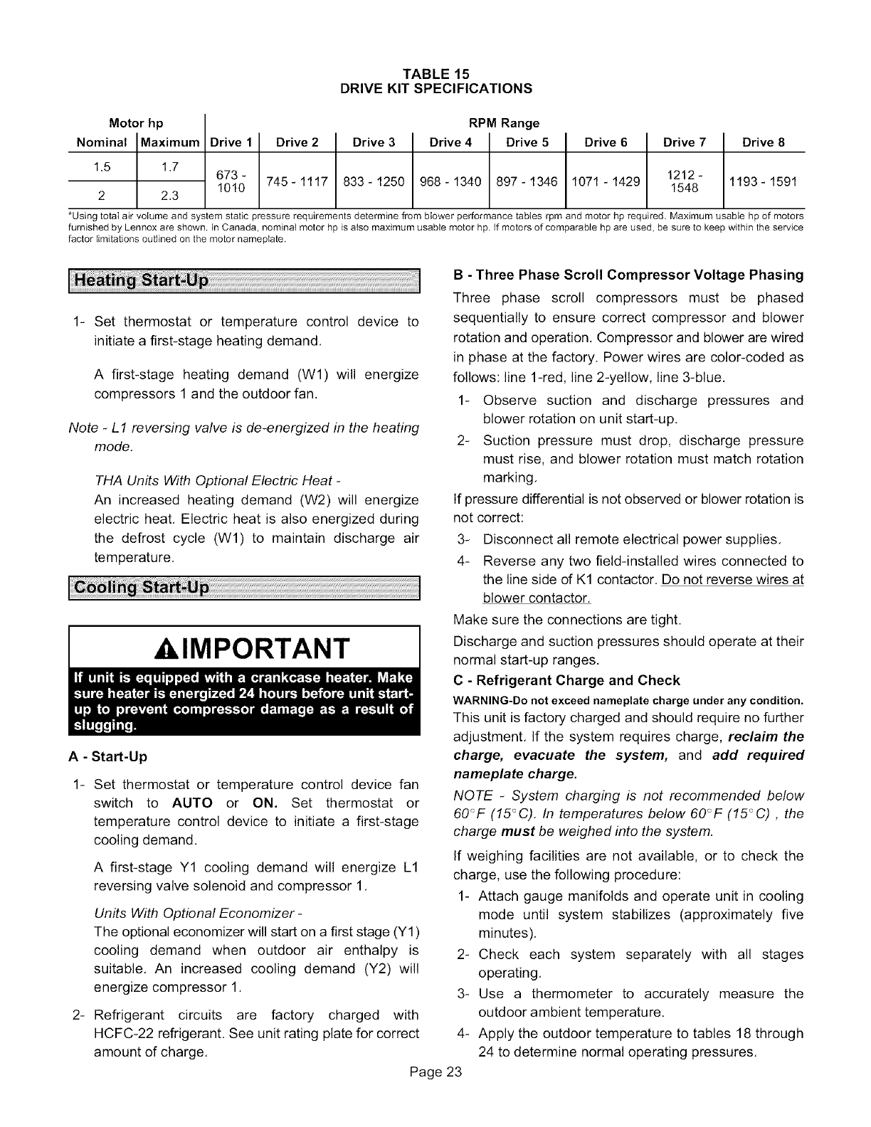
TABLE 15
DRIVE KIT SPECIFICATIONS
Motor hp
Nominal Maximum
1.5 1.7
2 2.3
Drive 2
673- 745-1117
1010
Drive 3
833-1250
RPM Range
Drive 4 Drive 5
968-1340 897-1346
Drive 6
1071-1429
Drive 7
1212-
1548
Drive 8
1193-1591
*Using total air volume and system static pressure requirements determine from blower performance tables rpm and motor hp required. Maximum usable hp of motors
furnished by Lennox are shown. In Canada, nominal motor hp is also maximum usable motor hp. if motors of comparable hp are used, be sure to keep within the service
factor bimitations outlined on the motor nameplate.
1- Set thermostat or temperature control device to
initiate a first-stage heating demand.
A first-stage heating demand (W1) will energize
compressors 1 and the outdoor fan.
Note -L1 reversing valve is de-energized in the heating
mode.
THA Units With Optional Electric Heat -
An increased heating demand (W2) will energize
electric heat. Electric heat is also energized during
the defrost cycle (W1) to maintain discharge air
temperature.
,&,IMPORTANT
A - Start-Up
1- Set thermostat or temperature control device fan
switch to AUTO or ON. Set thermostat or
temperature control device to initiate a first-stage
cooling demand.
A first-stage Y1 cooling demand will energize L1
reversing valve solenoid and compressor 1,
Units With Optional Economizer -
The optional economizer will start on a first stage (Y1)
cooling demand when outdoor air enthalpy is
suitable, An increased cooling demand (Y2) will
energize compressor 1,
2- Refrigerant circuits are factory charged with
HCFC-22 refrigerant. See unit rating plate for correct
amount of charge.
Page 23
B - Three Phase Scroll Compressor Voltage Phasing
Three phase scroll compressors must be phased
sequentially to ensure correct compressor and blower
rotation and operation. Compressor and blower are wired
in phase at the factory. Power wires are color-coded as
follows: line 1-red, line 2-yellow, line 3-blue.
1- Observe suction and discharge pressures and
blower rotation on unit start-up.
2- Suction pressure must drop, discharge pressure
must rise, and blower rotation must match rotation
marking.
If pressure differential is not observed or blower rotation is
not correct:
3- Disconnect all remote electrical power supplies.
4- Reverse any two field-installed wires connected to
the line side dK1 contactor. Do not reverse wires at
blower contactor.
Make sure the connections are tight.
Discharge and suction pressures should operate at their
normal start-up ranges.
C- Refrigerant Charge and Check
WARNING-Do not exceed nameplate charge under any condition.
This unit is factory charged and should require no further
adjustment. If the system requires charge, reclaim the
charge, evacuate the system, and add required
nameplate charge.
NOTE -System charging is not recommended below
60'_F (15_C). In temperatures below 60'_F (15_C) , the
charge must be weighed into the system.
If weighing facilities are not available, or to check the
charge, use the following procedure:
1- Attach gauge manifolds and operate unit in cooling
mode until system stabilizes (approximately five
minutes).
2- Check each system separately with all stages
operating.
3- Use a thermometer to accurately measure the
outdoor ambient temperature.
4- Apply the outdoor temperature to tables 18 through
24 to determine normal operating pressures.
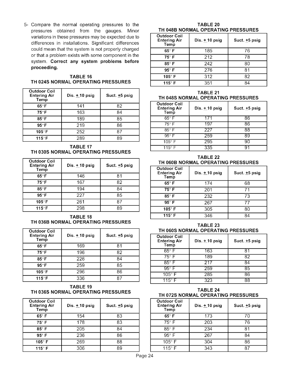
5- Comparethe normaloperatingpressuresto the
pressuresobtained from the gauges, Minor
variationsinthesepressuresmaybeexpecteddueto
differencesin installations.Significantdifferences
couldmeanthatthesystemisnotproperlycharged
orthata problemexistswithsomecomponentinthe
system,Correctany system problems before
proceeding.
TABLE 16
TH 024S NORMAL OPERATING PRESSURES
Outdoor Coil
Entering Air Dis. +10 psig Suct. +5 psig
Temp
65°F 141 82
75 oF 163 84
85 oF 189 85
95°F 219 86
105°F 252 87
115°F 289 89
TABLE 17
TH 030S NORMAL OPERATING PRESSURES
Outdoor Coil
Entering Air Dis. +10 psig Suct. +5 psig
Temp
65°F 146 81
75 oF 167 82
85 oF 194 84
95°F 227 85
105°F 261 87
115°F 298 89
TABLE 18
TH 036B NORMAL OPERATING PRESSURES
Outdoor Coil
Entering Air Dis. +10 psig Suct. +5 psig
Temp
65°F 169 81
75 oF 196 82
85°F 226 84
95°F 259 85
105°F 296 86
115°F 336 87
TABLE 19
TH 036S NORMAL OPERATING PRESSURES
Outdoor Coil
Entering Air Dis. +10 psig Suct. +5 psig
Temp
65o F 154 83
75o F 178 83
85° F2O5 84
95° F 236 86
105 oF269 88
115 ° F 306 89
Page 24
TABLE 20
TH 048B NORMAL OPERATING PRESSURES
Outdoor Coil
Entering Air Dis. + 10 psig Suct. +5 psig
Temp
65° F185 76
75° F 212 78
85° F242 80
95o F 276 81
105 o F 312 82
115 ° F 351 84
TABLE 21
TH 048S NORMAL OPERATING PRESSURES
Outdoor Coil
Entering Air Dis. + 10 psig Suct. +5 psig
Temp
65° F 171 86
75° F 197 86
85° F 227 88
95° F 259 89
105 ° F 295 90
115 ° F 335 91
TABLE 22
TH 060B NORMAL OPERATING PRESSURES
Outdoor Coil
Entering Air Dis. + 10 psig Suct. +5 psig
Temp
65o F174 68
75o F 201 71
85o F 232 73
95° F 267 77
105 oF305 80
115 o F 346 84
TABLE 23
TH 060S NORMAL OPERATING PRESSURES
Outdoor Coil
Entering Air Dis. + 10 psig Suct. +5 psig
Temp
65 ° F 163 81
75 ° F 189 82
85 ° F 217 84
95 ° F 259 85
105 ° F 285 86
115 ° F 323 88
TABLE 24
TH 072S NORMAL OPERATING PRESSURES
Outdoor Coil
Entering Air Dis. + 10 psig Suct. +5 psig
Temp
65° F173 70
75 ° F 203 76
85 ° F 234 81
95 ° F 267 84
105 ° F 304 86
115 ° F 343 87
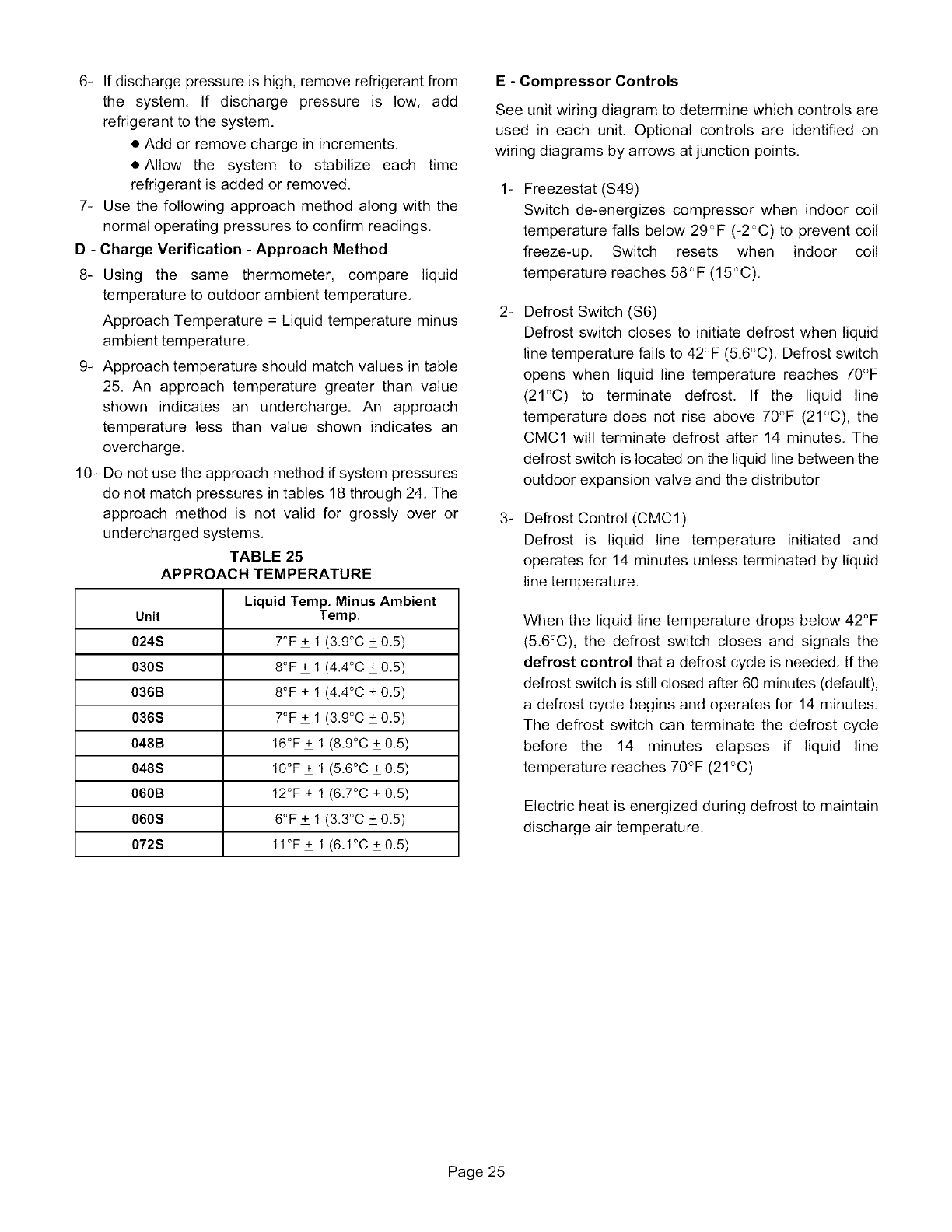
6- If discharge pressure is high, remove refrigerant from
the system, If discharge pressure is low, add
refrigerant to the system.
• Add or remove charge in increments.
• Allow the system to stabilize each time
refrigerant is added or removed.
7- Use the following approach method along with the
normal operating pressures to confirm readings.
D - Charge Verification - Approach Method
8-Using the same thermometer, compare liquid
temperature to outdoor ambient temperature,
Approach Temperature = Liquid temperature minus
ambient temperature,
9- Approach temperature should match values in table
25. An approach temperature greater than value
shown indicates an undercharge. An approach
temperature less than value shown indicates an
overcharge,
10- Do not use the approach method if system pressures
do not match pressures in tables 18 through 24, The
approach method is not valid for grossly over or
undercharged systems.
TABLE 25
APPROACH TEMPERATURE
Liquid Temp. Minus Ambient
Unit Temp.
024S 7°F + 1 (3.9°C + 0.5)
030S 8°F + 1 (4.4°C + 0.5)
036B 8°F + 1 (4.4°C + 0.5)
036S 7°F + 1 (3.9°C + 0.5)
048B 16°F+ 1 (8.9°C + 0.5)
048S 10°F+ 1 (5.6°C + 0.5)
060B 12°F+ 1 (6.7°C + 0.5)
060S 6°F + 1 (3.3°C + 0.5)
072S 11°F+ 1 (6.1°C +0.5)
E- Compressor Controls
See unit wiring diagram to determine which controls are
used in each unit, Optional controls are identified on
wiring diagrams by arrows at junction points.
-Freezestat (S49)
Switch de-energizes compressor when indoor coil
temperature falls below 29_F (-2<_C)to prevent coil
freeze-up, Switch resets when indoor coil
temperature reaches 58_F (15<_C).
.Defrost Switch ($6)
Defrost switch closes to initiate defrost when liquid
line temperature falls to 42°F (5.6°C), Defrost switch
opens when liquid line temperature reaches 70°F
(21°C) to terminate defrost. If the liquid line
temperature does not rise above 70°F (21°C), the
CMC1 will terminate defrost after 14 minutes. The
defrost switch is located on the liquid line between the
outdoor expansion valve and the distributor
_Defrost Control (CMC1)
Defrost is liquid line temperature initiated and
operates for 14 minutes unless terminated by liquid
line temperature.
When the liquid line temperature drops below 42°F
(5.6°C), the defrost switch closes and signals the
defrost control that a defrost cycle is needed, If the
defrost switch is still closed after 60 minutes (default),
a defrost cycle begins and operates for 14 minutes.
The defrost switch can terminate the defrost cycle
before the 14 minutes elapses if liquid line
temperature reaches 70°F (21°C)
Electric heat is energized during defrost to maintain
discharge air temperature.
Page 25
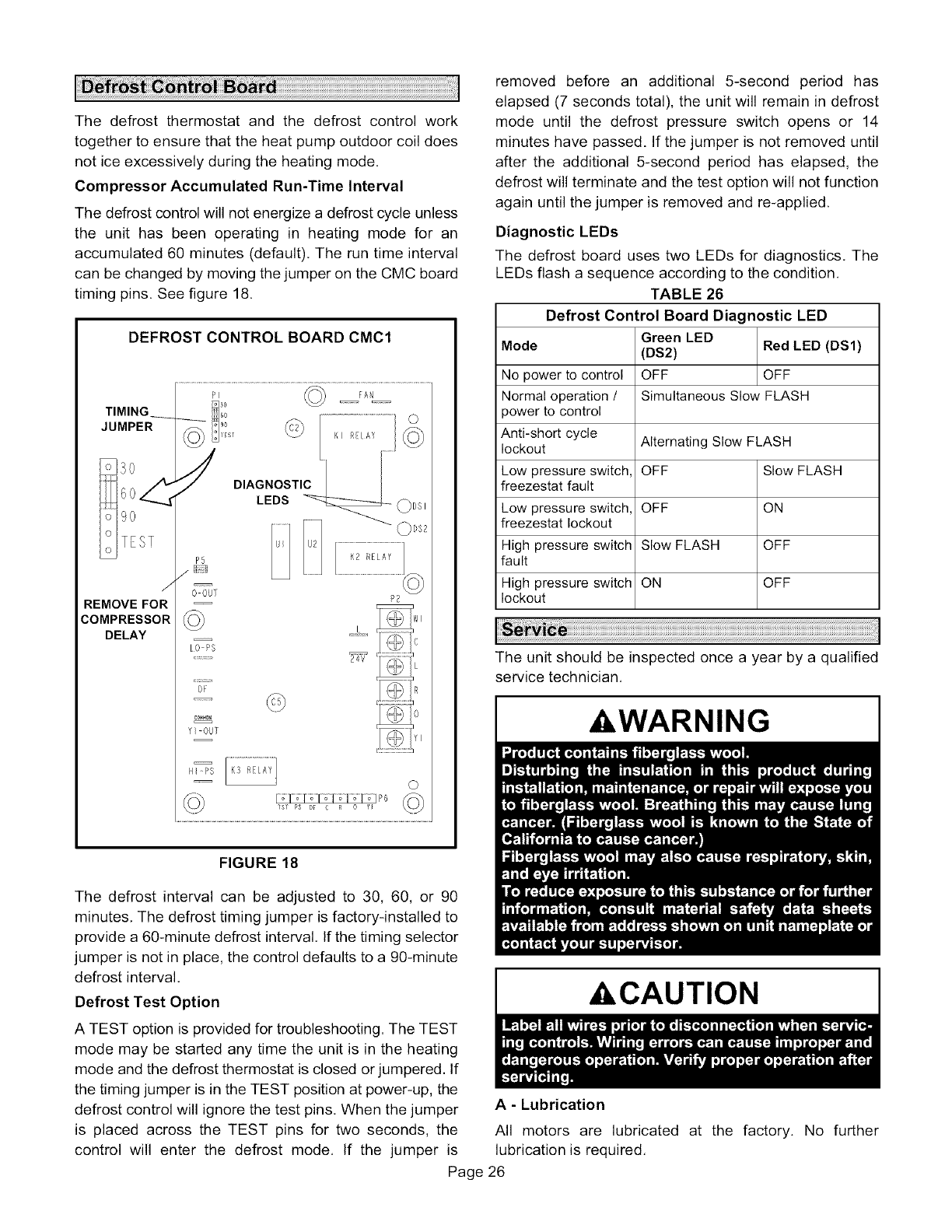
Thedefrostthermostatand the defrostcontrolwork
togethertoensurethattheheatpumpoutdoorcoildoes
noticeexcessivelyduringtheheatingmode.
Compressor Accumulated Run-Time Interval
The defrost control will not energize a defrost cycle unless
the unit has been operating in heating mode for an
accumulated 60 minutes (default). The run time interval
can be changed by moving the jumper on the CMC board
timing pins. See figure 18.
DEFROST CONTROLBOARD CMC1
TIMING
JUMPER
TEST
J
REMOVEFOR
COMPRESSOR
DELAY
P} @ FA
©" I_s/ \/' KI REtAY
DIAGNOSTIC
LEDS ___ 0 Ds2
P5 K2 RELAY
/_i-[I .................................................
0 OUT P2
I0 PS C
.......... 24V
FIGURE 18
The defrost interval can be adjusted to 30, 60, or 90
minutes. The defrost timing jumper is factory-installed to
provide a 60-minute defrost interval. If the timing selector
jumper is not in place, the control defaults to a 90-minute
defrost interval.
Defrost Test Option
A TEST option is provided for troubleshooting. The TEST
mode may be started any time the unit is in the heating
mode and the defrost thermostat is closed or jumpered. If
the timing jumper is in the TEST position at power-up, the
defrost control will ignore the test pins. When the jumper
is placed across the TEST pins for two seconds, the
control will enter the defrost mode. If the jumper is
Page 26
removed before an additional 5-second period has
elapsed (7 seconds total), the unit will remain in defrost
mode until the defrost pressure switch opens or 14
minutes have passed. If the jumper is not removed until
after the additional 5-second period has elapsed, the
defrost will terminate and the test option will not function
again until the jumper is removed and re-applied.
Diagnostic LEDs
The defrost board uses two LEDs for diagnostics. The
LEDs flash a sequence according to the condition.
TABLE 26
Defrost Control Board Diagnostic LED
Green LED
Mode (DS2) Red LED (DS1)
No power to control OFF OFF
Normal operation /Simultaneous Slow FLASH
power to control
Anti-short cycle
lockout Alternating Slow FLASH
Low pressure switch, OFF Slow FLASH
freezestat fault
Low pressure switch, OFF ON
freezestat lockout
High pressure switch Slow FLASH OFF
fault
High pressure switch ON OFF
lockout
The unit should be inspected once a year by a qualified
service technician.
,WARNING
,CAUTION
A-Lubrication
All motors are lubricated
lubrication is required,
at the factory. No further

B - Filters
Units are equipped with temporary flters which need to be
replaced before the building is occupied. See table 27 for
correct filter size. Refer to local codes or appropriate
jurisdiction for approved filters.
Approved filters should be checked monthly and replaced
when necessary. Take note of air flow direction marking
on filter frame when reinstalling filters. See figure 19.
&WARNING
TABLE 27
UNIT FILTERS
Qt
Unit Filter Size - inches (mm)
Y
024, 030, 4 16 X 20 X 2 (406 X 508 X
036, 048,060B 51)
20 X 20 X 2(508 X 508 X
060S, 072 4 51)
NOTE-Filtersmust be U.L.C. certified or equivalent _r
usein Canada.
C-Supply Air Blower Wheel
Annually inspect supply air blower wheel for accumulated
dirt or dust. Turn off power before attempting to remove
access panel or to clean blower wheel.
D - Indoor Coil
Inspect and clean coil at beginning of each cooling and
heating season. Clean using mild detergent or
commercial coil cleanser. Flush coil and condensate
drain with water taking care not to get insulation, filters
and return air ducts wet.
E- Outdoor Coil
Clean outdoor coil annually with detergent or commercial
coil cleaner and inspect monthly during the cooling
season.
Outdoor coils are made of single and two formed slabs.
On units with two slabs, dirt and debris may become
trapped between the slabs. To clean between slabs,
carefully separate coil slabs and wash them thoroughly.
See figure 20. Flush coils with water following cleaning.
Note -Remove all screws and gaskets prior to cleaning
procedure and replace upon completion.
F - Filter Drier
The unit is equipped with a biflow filter drier, if
replacement is necessary, order another of like design.
REMOVE FILTERS
PULL TO
REMOVE
FILTERS
FIGURE 19
0_
CLEAN OUTDOOR COIL
TOP VIEW
ENDPLATE IS SECURED
TO MULLION
OUTDOOR
COILS
1- Remove screws securing coil end plate to mullion.
2- Remove clips connecting coils slabs and separate
slabs 3-4" (76-102mm).
3- Clean coils with detergent or commercial coil cleaner.
4- Rinse thoroughly with water and reassemble.
FIGURE 20
Page 27
