LENNOX Package Units(both Units Combined) Manual L0806711
User Manual: LENNOX LENNOX Package Units(both units combined) Manual LENNOX Package Units(both units combined) Owner's Manual, LENNOX Package Units(both units combined) installation guides
Open the PDF directly: View PDF ![]() .
.
Page Count: 9
I STALLATIO AN
NTENANC iNSTRUCTiONS
(2,4)SA13
lectric Coolin
Series
Package Unit
TABLE OF CONTENTS
iNSTALLATiON ...................................... 2
OPERATION .......................................... 7
MAINTENANCE ..................................... 8
WiRiNG DIAGRAM ................................ 9
WARRANTY ........................................ 10
Manufactured By
A.A.C.
A Lennox International Inc. Company
421 Monroe Street
Bellevue, OH 44811
[A, CAUTION I
The installation of this appliance must conform to the requirements of the National Fire Protection Association;
the National Electrical Code, ANSI/NFPA No. 70 (latest edition) in the United States; the Canadian Electrical
Code Part 1, CSA 22.1 (latest edition) in Canada; and any state or provincial laws or local ordinances. Local
authorities having jurisdiction should be consulted before installation is made. Such applicable regulations or
requirements take precedence over the general instructions in this manual.
# 48392M005 Save these instructionsfor future reference Page 1
INSTALLATION
These instructions,and any instructions packaged with
mating components and/or accessories, should be care-
fully read prior to beginning installation. Note particularly
any CAUTIONS or WARNINGS in these instructionsand
all labels on the units.
These instructionsare intended as a general guide only, for
use by qualified personnel and do not supersede any national
or local codes inany way. Compliance with all local, state,
provincial, or national codes pertaining to this type of
equipment should be determined prior to installation.
These instructions explain the recommended method of
installation of the SA electric cooling unit and associated
electrical wi ring.
The SA unit is designed and approved for use as a self-
contained air-to-ai r air conditioning system.
The unit is factory equipped with a transformer and blower
control for applications without auxiliary heat. An electric
heat accessory kit (PHK) can be ordered for field installa-
tion of additional heat where required.
IMPORTANT: This product has been designed and manufac-
tured to meet ENERGY STAR criteria for energy efficiency.
However, proper refrigerant charge and proper air flow are
critical to achieve rated capacity and efficiency. Installation
of this product should follow the manufacturer's refrigerant
charging and air flow instructions.Failure to confirm
proper charge and airflow may reduce energy effi-
ciency and shorten equipment life.
inspection of Shipment
Upon receipt of equipment, carefully inspect it for possible
shipping damage. If damage is found, it should be noted on
the carrier's freight bill. Take special care to examine the
unit inside the carton if the carton is damaged. File a claim
with the transportation company.
If any damages are discovered and reported to the carrier
DO NOT INSTALL THE UNIT, as claim may be denied.
Check the unit rating plate to confirm specifications
are as ordered.
Limitations
The unit should be installed inaccordance with all national
and local safety codes.
Limitations of the unit and appropriate accessories must
also be observed.
The unit must not be installed with any ductwork in the
outdoor air stream. The outdoor fan is not designed to
operate against any additional static pressure.
Location
The unit is designed to be located outdoors with sufficient
clearance for free entrance to the air inlet and discharge air
openings. The location must also allow for adequate
service access.
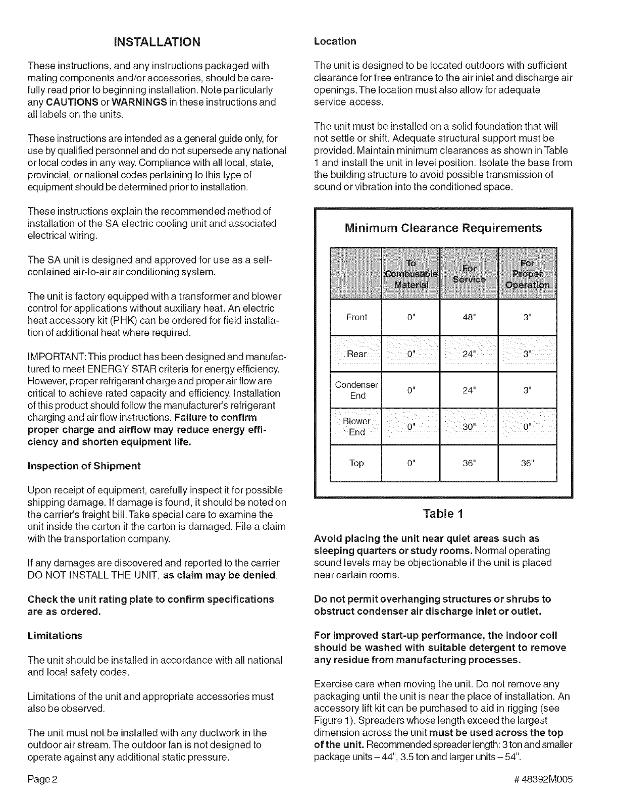
The unit must be installed on a solid foundation that will
not settle or shift. Adequate structural support must be
provided. Maintain minimum clearances as shown inTable
1 and install the unit in level position, isolate the base from
the building structure to avoid possible transmission of
sound or vibration into the conditioned space.
Minimum Clearance Requirements
Front 0" 48" 3"
3"
Rear .0". 24'
Condenser 0" 24" 3"
End
Top 0" 36" 36"
Table 1
Avoid placing the unit near quiet areas such as
sleeping quarters or study rooms. Normal operating
sound levels may be objectionable if the unit is placed
near certain rooms.
Do not permit overhanging structures or shrubs to
obstruct condenser air discharge inlet or outlet.
For improved start-up performance, the indoor coil
should be washed with suitable detergent to remove
any residue from manufacturing processes.
Exercise care when moving the unit. Do not remove any
packaging until the unit is near the place of installation. An
accessory lift kit can be purchased to aid in rigging (see
Figure 1). Spreaders whose length exceed the largest
dimension across the unit must be used across the top
of the unit. Recommended spreader length: 3ton and smaller
package units - 44", 3.5 ton and larger units - 54".
Page 2 # 48392M005
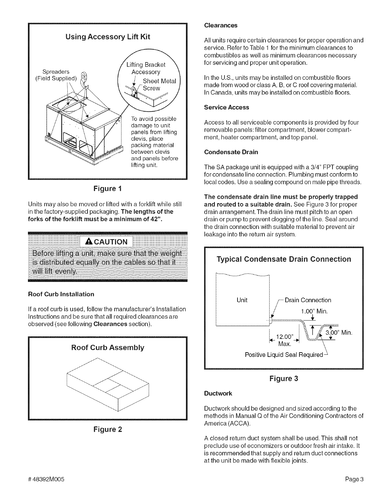
Using Accessory Lift Kit
Spreaders
(Field Supplied)
To avoid possible
damage to unit
panels from lifting
clevis, place
packing material
between clevis
and panels before
lifting unit,
Figure 1
Units may also be moved or lifted with a forklift while still
in the factory-supplied packaging. The lengths of the
forks of the forklift must be a minimum of 42".
Roof Curb Installation
If a roof curb is used, follow the manufacturer's Installation
Instructions and be sure that all required clearances are
observed (see following Clearances section).
Roof Curb Assembly
Figure 2
Clearances
All units require certain clearances for proper operation and
service. Refer to Table 1 for the minimum clearances to
combustibles as well as minimum clearances necessary
for servicing and proper unit operation.
In the U.S., units may be installed on combustible floors
made from wood or class A, B, or C roof covering material.
In Canada, units may be installed on combustible floors.
Service Access
Access to all serviceable components is provided by four
removable panels: filter compartment, blower compart-
ment, heater compartment, and top panel.
Condensate Drain
The SA package unit is equipped with a 3/4" FPT coupling
for condensate line connection. Plumbing must conform to
local codes. Use a sealing compound on male pipe threads.
The condensate drain line must be properly trapped
and routed to a suitable drain. See Figure 3 for proper
drain arrangement. The drain line must pitch to an open
drain or pump to prevent clogging of the line. Seal around
the drain connection with suitable material to prevent air
leakage into the return air system.
Typical Condensate Drain Connection
Unit /-- Drain Connection
/1.00" Min.
t2.oo -
'- Max. °' _\
Positive Liquid Seal Required _
Figure 3
Ductwork
Ductwork should be designed and sized according to the
methods in Manual Q of the Air Conditioning Contractors of
America (ACCA).
A closed return duct system shall be used. This shall not
preclude use of economizers or outdoor fresh air intake. It
is recommended that supply and return duct connections
at the unit be made with flexible joints.
# 48392M005 Page 3
Thesupplyandreturnairductsystemsshouldbede-
signedfortheCFMandstaticrequirementsofthejob.
They should not be sized by matching the dimensions
of the duct connections on the unit.
Outdoor ductwork must be insulated and waterproofed.
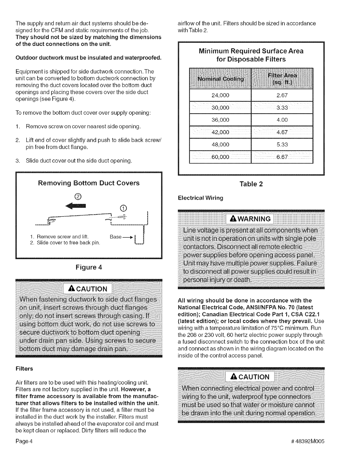
Equipment is shipped for side ductwork connection. The
unit can be converted to bottom ductwork connection by
removing the duct covers located over the bottom duct
openings and placing these covers over the side duct
openings (see Figure 4).
To remove the bottom duct cover over supply opening:
1. Remove screw on cover nearest side opening.
2. Lift end of cover slightly and push to slide back screw/
pin free from duct flange.
3. Slide duct cover out the side duct opening.
Removing Bottom Duct Covers
®
41111
1. Remove screw and lift.
2. Slide cover to free back pin.
(D
Base_
J
Figure 4
airflow of the unit. Filters should be sized in accordance
with Table 2.
Minimum Required Surface Area
for Disposable Filters
24,000 2.67
36,000 4.00
42,000 .4.67
48,000 5.33
Table 2
Electrical Wiring
Filters
Air filters are to be used with this heating/cooling unit.
Filters are not factory supplied in the unit. However, a
filter frame accessory is available from the manufac-
turer that allows filters to be installed within the unit.
If the filter frame accessory is not used, a filter must be
installed in the duct work by the installer. Filters must
always be installed ahead of the evaporator coil and must
be kept clean or replaced. Dirty filters will reduce the
All wiring should be done in accordance with the
National Electrical Code, ANSI/NFPA No. 70 (latest
edition); Canadian Electrical Code Part 1, CSA C22.1
(latest edition); or local codes where they prevail. Use
wiring with a temperature limitation of 75°C minimum. Run
the 208 or 230 volt, 60 hertz electric power supply through
a fused disconnect switch to the connection box of the unit
and connect as shown in the wiring diagram located on the
inside of the control access panel.
Page 4 # 48392M005
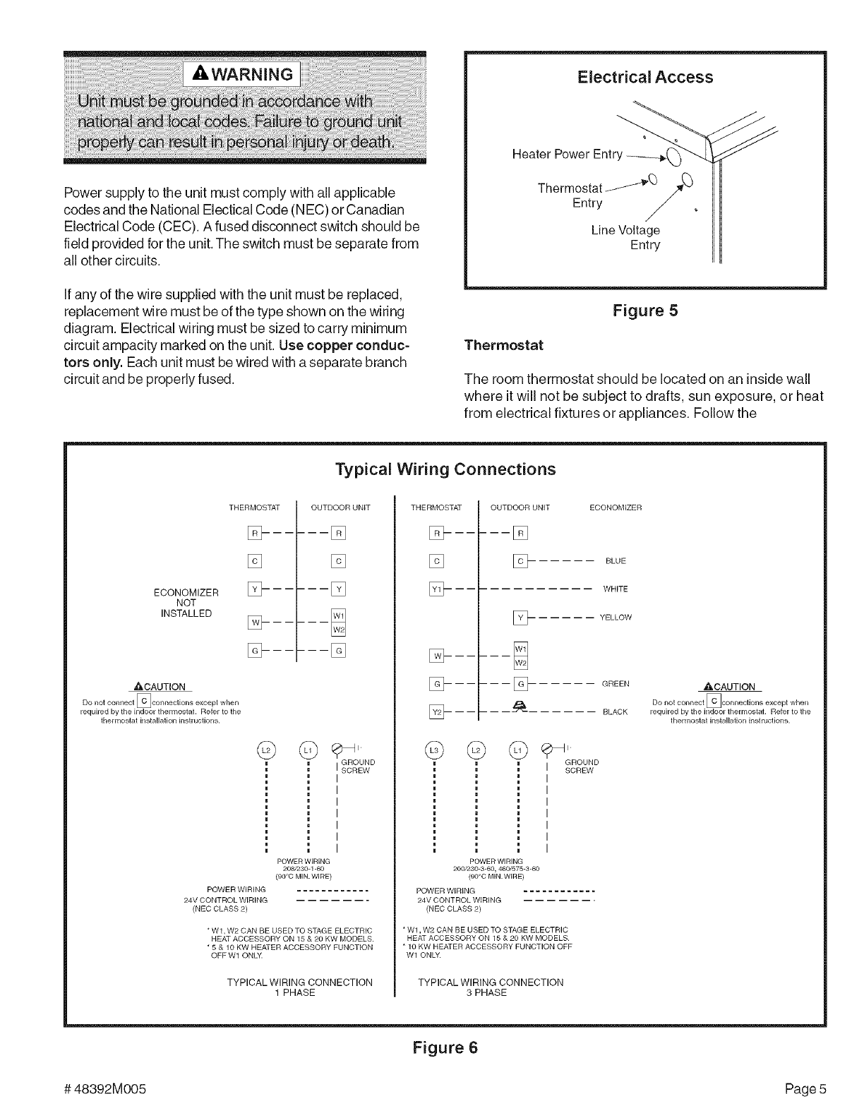
Powersupplytotheunitmustcomplywithallapplicable
codesandtheNationalElecticalCode(NEC)orCanadian
ElectricalCode(CEC).Afuseddisconnectswitchshouldbe
fieldprovidedfortheunit.Theswitchmustbeseparatefrom
allothercircuits.
Ifanyofthewiresuppliedwiththeunitmustbereplaced,
replacementwiremustbeofthetypeshownonthewiring
diagram.Electricalwiringmustbesizedtocarryminimum
circuitampacitymarkedontheunit.Usecopperconduc-
torsonly.Eachunitmustbewiredwithaseparatebranch
circuitandbeproperlyfused.
Electrical Access
Heater Power
Thermostat _Q_
Entry
Line Voltage
Entry
Figure 5
Thermostat
The room thermostat should be located on an inside wall
where it will not be subject to drafts, sun exposure, or heat
from electrical fixtures or appliances. Follow the
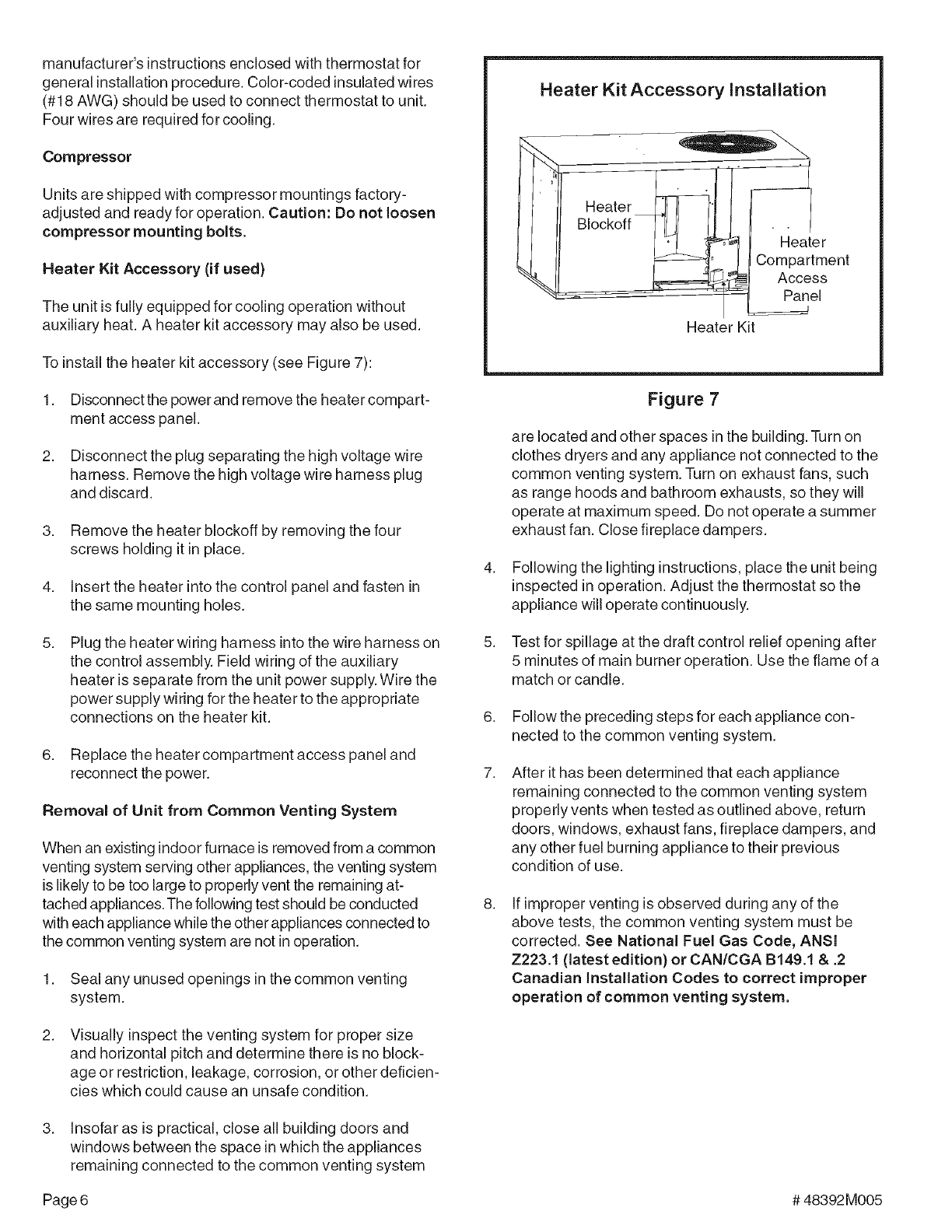
Typical Wiring Connections
ECONOMIZER
NOT
INSTALLED
THERMOSTAT
E_------
[]
[_------
[_-- -- --
[_----
_CAUTION
Do not connect [CJeonnections except when
required by the indoor thermostat. Refer to the
thermostat installation instructions.
@
OUTDOOR UNIT
-----[]
[]
-----[_
(_ _'GROUND
ISCREW
POWER WIRING
208/230=1-60
(gO°C MIN. WIRE)
POWER WIRING
24V CONTROL WIRING
(NED CLASS 2)
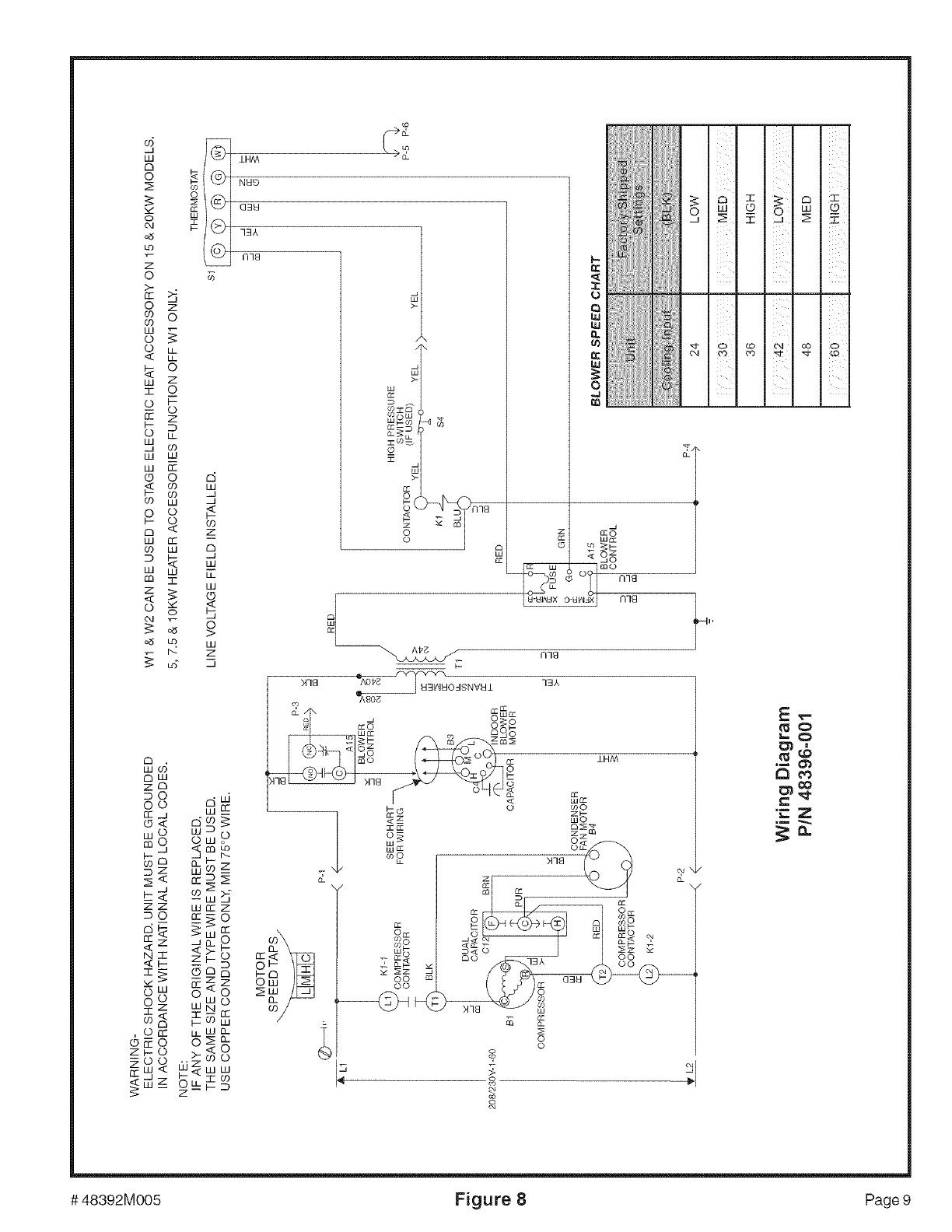
* W1, W2 CAN BE USED TO STAGE ELECTRIC
HEAT ACCESSORY ON 15 & 20 KW MODELS.
* 5 & 10 KW HEATER ACCESSORY FUNCTION
OFFW1 ONLY.
TYPICAL WIRING CONNECTI©N
1 PHASE
THERMOSTAT
E_------
[]
[_-- ----
[_----
@
OUTDOOR UNIT ECONOMIZER
-----[]
] BLUE
WHITE
] YELLOW
- -- -- [_ GREEN
- -- --d_--- BLACK
GROUND
SCREW
POWER WIRING
200/230-3-60, 460/575-3=60
(90°C MIN.WIRE)
POWER WIRING ............
24V CONTROL WIRING
(NED CLASS 2)
Wl, W2 CAN BE USED TO STAGE ELECTRIC
HEAT ACCESSORY ON 15 & 20 KW MODELS.
10 KW HEATER ACCESSORY FUNCTION OFF
Wl ONLY.
TYPICAL WIRING CONNECTION
3 PHASE
AOAUTION
Do not connect [CJconnections except when
required by the indoor thermostat. Refer to the
thermostat installation instructions.
Figure 6
# 48392M005 Page 5
manufacturer'sinstructionsenclosedwiththermostatfor
generalinstallationprocedure.Color-codedinsulatedwires
(#18AWG)shouldbeusedtoconnectthermostattounit.
Fourwiresarerequiredforcooling.
Compressor
Units are shipped with compressor mountings factory-
adjusted and ready for operation. Caution: Do not loosen
compressor mounting bolts.
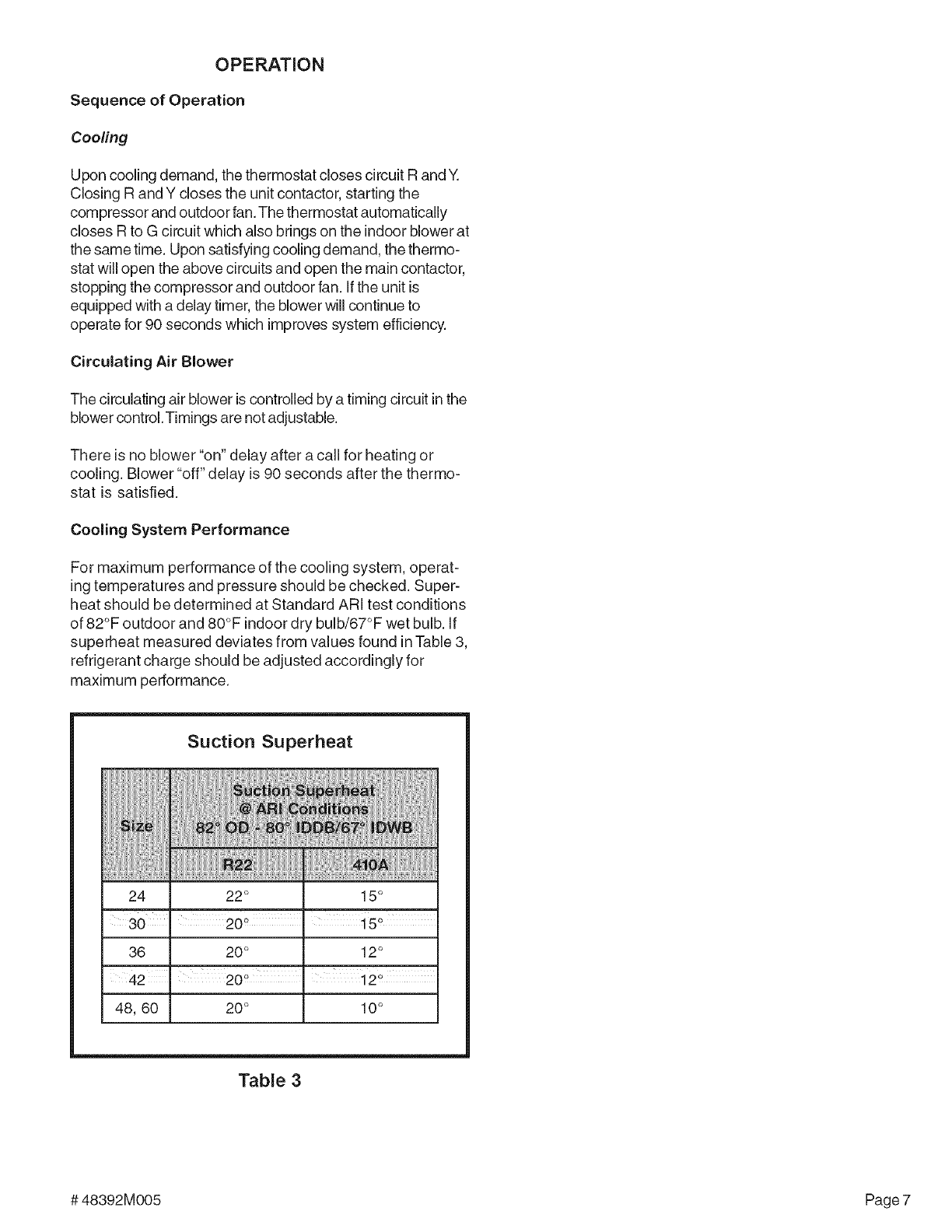
Heater Kit Accessory (if used)
The unit is fully equipped for cooling operation without
auxiliary heat. A heater kit accessory may also be used.
To install the heater kit accessory (see Figure 7):
1. Disconnectthe powerand remove the heatercompart-
ment access panel.
2. Disconnect the plug separating the high voltage wire
harness. Remove the high voltage wire harness plug
and discard.
3. Remove the heater blockoff by removing the four
screws holding it in place.
4. insert the heater into the control panel and fasten in
the same mounting holes.
Plug the heater wiring harness into the wire harness on
the control assembly. Field wiring of the auxiliary
heater is separate from the unit power supply. Wire the
power supply wiring for the heater to the appropriate
connections on the heater kit.
6. Replace the heater compartment access panel and
reconnect the power.
Removal of Unit from Common Venting System
When an existing indoor furnace is removed from a common
venting system serving other appliances, the venting system
is likely to be too large to properly vent the remaining at-
tached appliances. The following test should be conducted
with each appliance while the other appliances connected to
the common venting system are not in operation.
1. Seal any unused openings in the common venting
system.
2. Visually inspect the venting system for proper size
and horizontal pitch and determine there is no block-
age or restriction, leakage, corrosion, or other deficien-
cies which could cause an unsafe condition.
3. insofar as is practical, close all building doors and
windows between the space in which the appliances
remaining connected to the common venting system
Heater Kit Accessory Installation
IHeater _!_i
Blockoff
, =
ent
Panel
Heater Kit
Figure 7
are located and other spaces in the building. Turn on
clothes dryers and any appliance not connected to the
common venting system. Turn on exhaust fans, such
as range hoods and bathroom exhausts, so they will
operate at maximum speed. Do not operate a summer
exhaust fan. Close fireplace dampers.
4. Following the lighting instructions, place the unit being
inspected in operation. Adjust the thermostat so the
appliance will operate continuously.
5. Test for spillage at the draft control relief opening after
5 minutes of main burner operation. Use the flame of a
match or candle.
6. Follow the preceding steps for each appliance con-
nected to the common venting system.
7. After it has been determined that each appliance
remaining connected to the common venting system
properly vents when tested as outlined above, return
doors, windows, exhaust fans, fireplace dampers, and
any other fuel burning appliance to their previous
condition of use.
8. If improper venting is observed during any of the
above tests, the common venting system must be
corrected. See National Fuel Gas Code, ANSI
Z223.1 (latest edition)or CAN/CGA B149.1 & .2
Canadian installation Codes to correct improper
operation of common venting system.
Page 6 # 48392M005
OPERATION
Sequence of Operation
CooHng
Upon cooling demand, the thermostat closes circuit R and Y.
Closing R and Y closes the unit contactor, starting the
compressor and outdoor fan.The thermostat automatically
closes R to G circuit which also brings on the indoor blower at
the same time. Upon satisfying cooling demand, the thermo-
stat will open the above circuits and open the main contactor,
stopping the compressor and outdoor fan. (f the un(t is
equipped with a delay timer, the blower will continue to
operate for 90 seconds wh(ch improves system efficiency.
Circulating Air Blower
The circulating air blower is controlled by a timing circuit in the
blower control. Timings are not adjustable.
There is no blower "on" delay after a call for heating or
cooling. Blower "off" delay is 90 seconds after the thermo-
stat is satisfied.
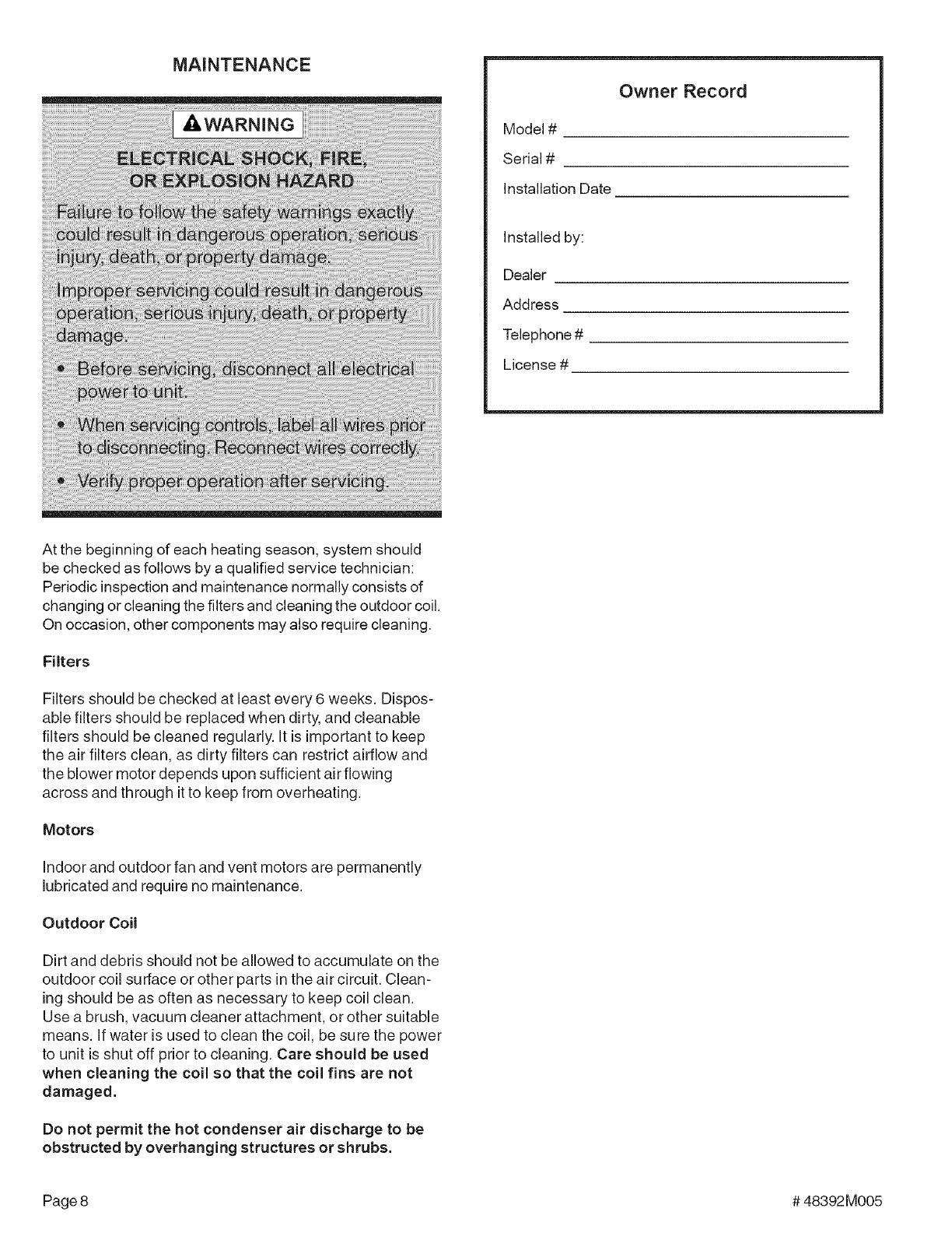
Cooling System Performance
For maximum performance of the cooling system, operat-
ing temperatures and pressure should be checked. Super-
heat should be determined at Standard AR( test conditions
of 82°F outdoor and 80°F indoor dry bulb/67°F wet bulb. (f
superheat measured deviates from values found in Table 3,
refrigerant charge should be adjusted accordingly for
maximum performance.
Suction Superheat
22°
20°
15°
12°
48,60 20° 10°
Table 3
# 48392M005 Page 7
MAINTENANCE
Owner Record
Model #
Serial #
Installation Date
Installed by:
Dealer
Address
Telephone #
License #
At the beginning of each heating season, system should
be checked as follows by a qualified service technician:
Periodic inspection and maintenance normally consists of
changing or cleaning the filters and cleaning the outdoor coil.
On occasion, other components may also require cleaning.
Filters
Filters should be checked at least every 6 weeks. Dispos-
able filters should be replaced when dirty, and cleanable
filters should be cleaned regularly. It is important to keep
the air filters clean, as dirty filters can restrict airflow and
the blower motor depends upon sufficient air flowing
across and through it to keep from overheating.
Motors
indoor and outdoor fan and vent motors are permanently
lubricated and require no maintenance.
Outdoor Coil
Dirt and debris should not be allowed to accumulate on the
outdoor coil surface or other parts in the air circuit. Clean-
ing should be as often as necessary to keep coil clean.
Use a brush, vacuum cleaner attachment, or other suitable
means. If water is used to clean the coil, be sure the power
to unit is shut off prior to cleaning. Care should be used
when cleaning the coil so that the coil fins are not
damaged.
Do not permit the hot condenser air discharge to be
obstructed by overhanging structures or shrubs.
Page 8 # 48392M005
05
d
w
d3
0
o
o
oJ
LO
Z
o co
>-
o z
co o
09
W
0 L£
< LL
o
w Z
7- 0
-- ©
£:: Z
1-
o2
w
d o9
w LU
w
@ 0 d
_J
09 w d
D z
w rr --
09 w I23
w
o
_ ko w
_ b2 z
w_
_w
Z_
_o _
2° @
8 w_w Ow
_ o
D --
-- -- w
ZZ W_Z
D_ _o
_ ©
Z
N_ Z_
_8 o_
> O
_z omZ _
Z--
±HM
NN9
N78
>
>
_IO {
_ow
CC--D
>-
N7g z _S
w_
08
I
I I ON7g
I u-_x o-_axj n78
ss _
{
ol_
M7g _AOP8 _Ng_NOgSNV£11 73A
mo _ IHM
< _cc
M78 o_
_ __ cc
::/ ZI/_ o::
o o9
OI I ccO
So
_o 73A 08
oo @
oo
co _
o
o
N
ii i ii
"q- 0 ¢D 04 CO C_
cd eO cO _- ,q- _0
E
"_ Z
# 48392M005 Figure 8 Page 9
