LENNOX Furnace/Heater, Gas Manual L0806819
User Manual: LENNOX LENNOX Furnace/Heater, Gas Manual LENNOX Furnace/Heater, Gas Owner's Manual, LENNOX Furnace/Heater, Gas installation guides
Open the PDF directly: View PDF ![]() .
.
Page Count: 4
GAS KITS AND ACCESSORIES
© 2007 Lennox Industries Inc.
Dallas, Texas, USA 505,313M IGNITION CONTROL
0912007 REPLACEMENT KIT
INSTALLATION INSTRUCTIONS FOR IGNITION CONTROL REPLACEMENT KIT 30W33
(LB-90701C), USED TO REPLACE A ROBERTSHAW 735L (18G91) OR 745 (97H04) IGNITION
CONTROL, OR A JOHNSON G776 (63K2401, 41K8701 or 69J3601) IGNITION CONTROL
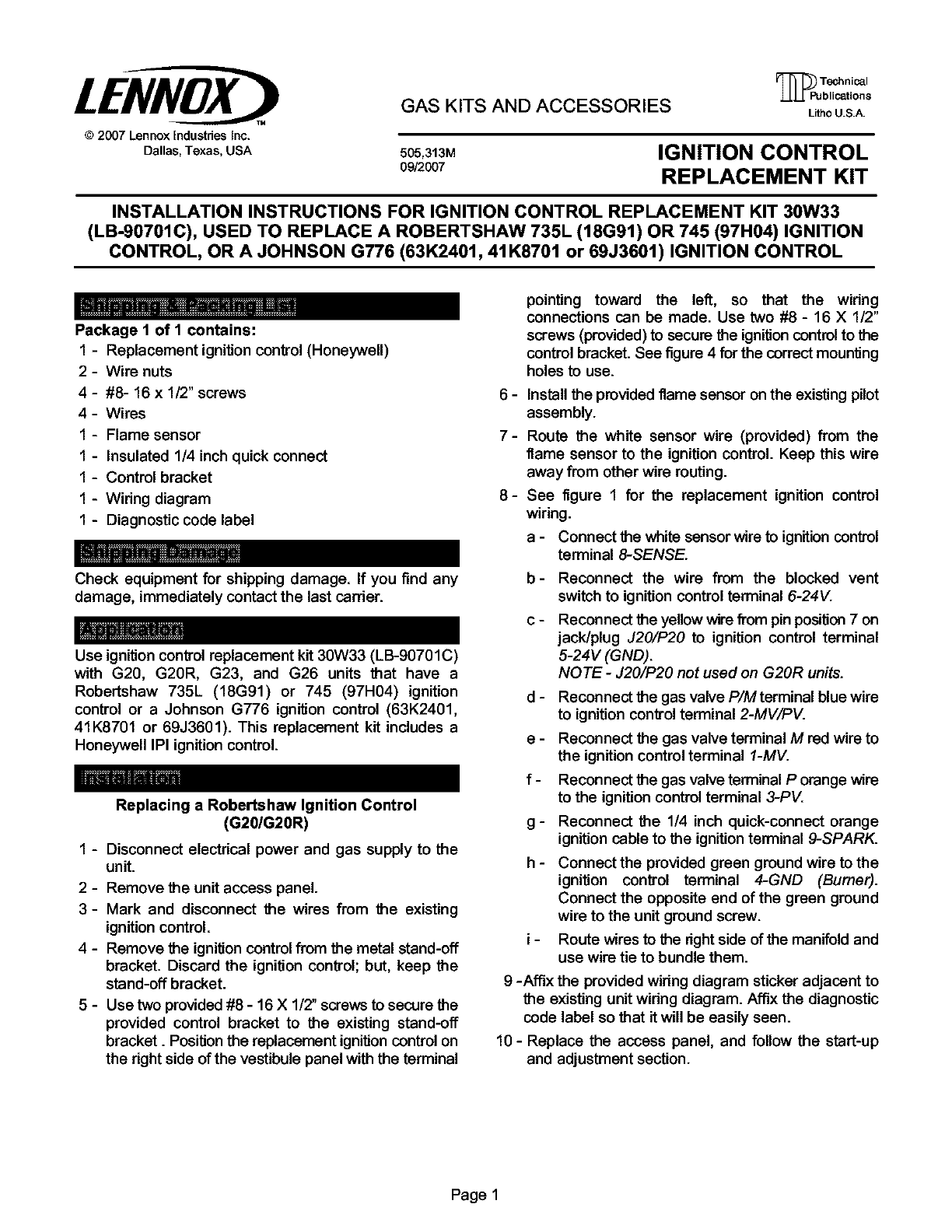
Package 1 of I contains:
I - Replacement ignition control (Honeywell)
2-Wire nuts
4-#8- 16 x 1/2" screws
4- Wires
1 - Flame sensor
1- Insulated 1/4 inch quick connect
1-Control bracket
1 - Widng diagram
1 - Diagnostic code label
Check equipment for shipping damage. If you find any
damage, immediately contact the last carder.
Use ignition control replacement kit 30W33 (LB-90701C)
with G20, G20R, G23, and G26 units that have a
Robertshaw 735L (18G91) or 745 (97H04) ignition
control or a Johnson G776 ignition control (63K2401,
41K8701 or 69J3601). This replacement kit includes a
Honeywell IPI ignition control.
Replacing a Robertshaw Ignition Control
(G20/G20R)
1 - Disconnect electrical power and gas supply to the
unit.
2 - Remove the unit access panel.
3- Mark and disconnect the wires from the existing
ignition control.
4-Remove the ignition control from the metal stand-off
bracket. Discard the ignition control; but, keep the
stand-off bracket.
5-Use two provided #8 -16 X1/2" screws to secure the
provided control bracket to the existing stand-off
bracket. Positionthe replacement ignition controlon
the right side of the vestibule panel with the t_rminal
pointing toward the left, so that the widng
connections can be made. Use two #8 - 16 X 1/2"
screws (provided) to secure the ignition control to the
control bracket. See figure 4 for the correct mounting
holes t_ use.
6 - Install the provided flame sensor on the existing pilot
assembly.
7- Rout_ the white sensor wire (provided) from the
flame sensor to the ignition control. Keep this wire
away from other wire routing.
8- See figure 1for the replacement ignition control
wiring.
a- Connect the whit_esensor wire to ignition control
terminal 8-SENSE.
b- Reconnect the wire from the blocked vent
switch to ignition control terminal 6-24V.
C- Reconnect the yellow wire ffom pin position7on
jack/plug J20/P20 to ignition control terminal
5-24V (GND).
NOTE - J20/P20 not used on G20R units.
d - Reconnect the gas valve P/Mterminal blue wire
to ignition control terminal 2-MV/PV.
e - Reconnect the gas valve terminal Mred wire to
the ignition control terminal 1-MV.
f - Reconnect the gas valve terminal Porange wire
to the ignition control terminal 3-PV.
g - Reconnect the 1/4 inch quick-connect orange
ignition cable to the ignitionterminal 9-SPARK.
h- Connect the provided green ground wire to the
ignition control terminal 4-GND (Bumer).
Connect the opposite end of the green ground
wire to the unit ground screw.
i-Route wires to the rightside of the manifold and
use wire tie to bundle them.
9 -Affix the provided wiring diagram sticker adjacent to
the existing unit widng diagram. Affix the diagnostic
code label so that it will be easily seen.
10 - Replace the access panel, and follow the start-up
and adjustment section.
Page 1
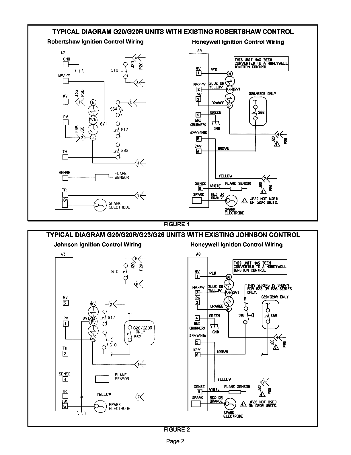
TYPICAL DIAGRAM G20/G20R UNITS WITH EXISTING ROBERTSHAW CONTROL
Robertshaw Ignition Control Wiring
A5
GNO
MV/RV
[]
MV
D--
PV
[]
TH
[]
SENSE
[D-
TR
[]
IGR
[D--
s,o _
<-
D-
is,7
562
FLAME
_SENSOR
_ SPARK
ELECTRODE
Honeywell Ignition Control Wiring
1
THIS UNIT HAS BEEN I
CONVERTED TO A HONEYWELL
1
ISNITIDN _NTROL
G20/G20R ONLY
©
FIGURE 1
TYPICAL DIAGRAM G20/G20R/G23/G26 UNITS WITH EXISTING JOHNSON CONTROL
Johnson Ignition Control Wiring Honeywell Ignition Control Wiring
A5 A3
i
I
MV
t
D
N O
510
GVI $47
GZO/G2OR
ONLY
562
_YELLOW FLAME
SENSOR
dL
_ELECTROOE
MY
[D--
NV/PV
N--
D\I
N---
6ND
24V<GNB)
N---
24V
[]
SENSE
SPARK
i
THIS UNIT HAS I{EN
CONVERTED TO AHONEywELL
RED IGNITION CONTROL
BLUE: OR FTHIS VIRING IS $FID_CN
YELLOV _FOR G23 I_ GE6 SERIES
VI ONLY, 6_0/6_0R ONLY
ER_ S_ (
ONBII _',4-
BROWN _
RED DR
JP_0 NOT USED
/_k ON G_ UNIT_
SPARK
ELEET_E
FIGURE 2
Page 2
Replacing a Johnson Ignition Control
(G201G20R/G231G26)
1-Disconnect electrical power and gas supply to the
unit.
2- Remove the unit access panel.
3- Mark and disconnect the wires from the existing
ignition control.
4-Use a 1/4" nut driver to remove the two #8-32 screws
that secure the existing ignition control to the unit.
Use two of the provided #8 - 16 X 1/2" screws to
install the provided control bracket in the unit. See
figure 4 for the correct mounting holes to use.
5-Posifion the replacement ignition control and bracket
so that the control terminals point toward the left for
G20 and G23 units. Position the control and bracket
so that the terminals point toward the bottom for G26
units. Secure the mounting bracket and Honeywell
control to the unit.
6-Reconnect the marked wires to the new control as
shown in figure 3 and as outlined below:
NOTE - On Johnson ignition controls 41K8701
and 631(2401, the MVand PV terminals will be 3/16"
quick connects. Use the provided 1/4" quick connect
pigtail wires to wire the Honeywell control t_rminals
MVand PV.
a- On the replacement control, locate the terminals
labeled 1-MV and 3-PV. The quick-connect
terminals on the new board are 1/4". Use the two
provided wires to connect to these terminals.
b- Cut the spade connector off of the e_isting wire
fTom terminal MV. Strip the wire back 5/8" and
use a wire nut to connect this wire to the wire
provided in the replacement kit. Connect the
spade end of the provided wire to the 1-MV
terminal on the replacement control.
C- Cut the spade connector off the existing wire
fTom terminal PV. Strip the wire back 5/8" and
use a wire nut to connect this wire to the wire
provided in the replacement kit. Connect the
spade end of the provided wire to the 3-PV
terminal on the control.
7- If the Johnson control is #69J3601 (G776 RDG-2) or
#74H2601 (G776 RDG-1), the MVand PVterminals
are 1/4" and they will connect directly to the 1/4"
Honeywell terminals.
8- Install the provided flame sensor on the exisfing pilot
assembly.
9- Rout_ the white sensor wire (provided) from the
flame sensor to the ignition control. Keep this wire
away from other wire routing.
10-See figure 2 for the replacement of the ignition
control wiring.
a- Connect the white sensor wire to ignitioncontrol
terminal 8-SENSE.
c - G20 and G20R units only- Reconnect the wire
from the blocked vent switch to ignifion control
terminal 6-24V.
d- G20, G23 and G26 units only -Reconnect the
yellow wire fTom pin position 7on jack/plug
J20/P20 to ignition control terminal 5-24V
(GND).
e-Reconnect the gas valve P/M terminal blue or
yellow wire to ignitioncontrol terminal 2-MV/PV.
f - Reconnect the gas valve terminal Mred wire to
the ignition control terminal 1-MV.
g - Reconnect the gas valve terminal Porange wire
to the ignition control terminal 3-PV.
h- Attach the provided insulated 1/4" quick connect
to the Johnson pilot red spark wire and connect
it to the ignition control terminal 9-SPARK.
i- Connect the provided green ground wire to the
ignition control terminal 4-GND (Burner).
Connect the opposite end of the green ground
wire to the unit ground screw.
11-Affix the provided wiring diagram sticker adjacent to
the existing unit wiring diagram. Affix the diagnostic
code label so that it will be easily seen.
12- Replace the access panel.
13-Restore the electrical power and gas supply to the
unit. Refer to the start-up and adjustment
procedures.
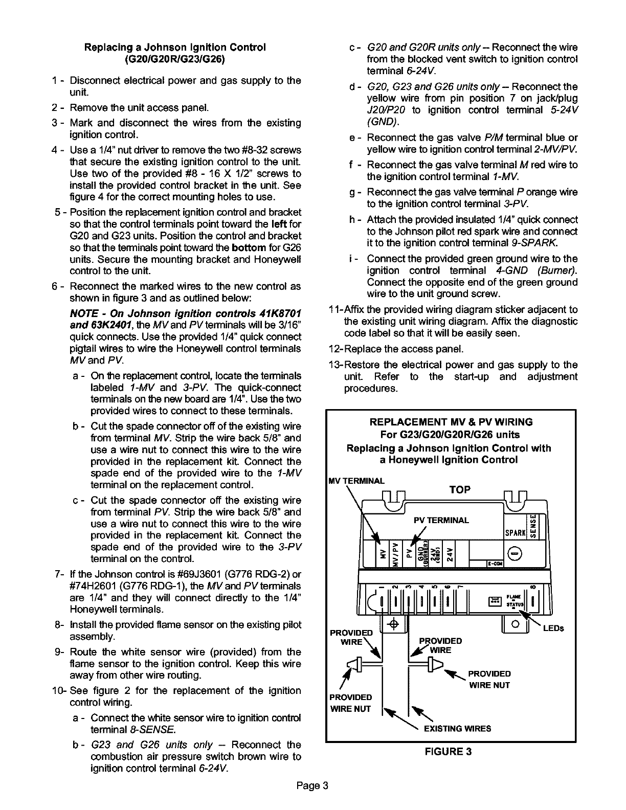
REPLACEMENT MV & PV WIRING
For G231G201G20R/G26 units
Replacing a Johnson Ignition Control with
a Honeywell Ignition Control
MVTERMINAL
\TOP
PV TERMINAL
PROVIDED
[]
'_ "_ IPROVIDED
I I W,RENUT
PROV'DEDI I
W,RENUTI r . X,ST,N, W,RES
b- G23 and G26 units only -Reconnect the
combustion air pressure switch brown wire to
ignifion control terminal 6-24V.
FIGURE 3
Page 3
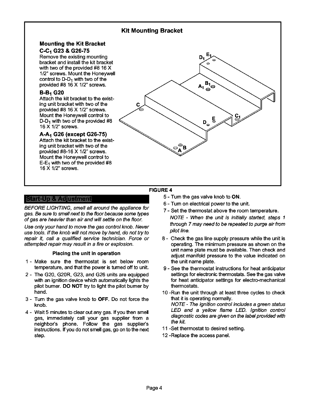
Mounting the Kit Bracket
C-C 1 G23 & G26-75
Remove the existing mounting
bracket and install the kit bracket
with two of the provided #8 16 X
1/2" screws. Mount the Honeywell
control to D-D1 with two of the
provided #8 16 X 1/2" screws.
B-B1 G20
Attach the kit bracket to the exist-
ing unit bracket with two of the
provided #8 16 X1/2" screws.
Mount the Honeywell control to
D-D 1with two of the provided #8
16 X 1/2" screws.
A-A 1 G26 (except G26-75)
Attach the kit bracket to the exist-
ing unit bracket with two of the
provided #8-16 X1/2" screws.
Mount the Honeywell control to
E-E 1with two of the provided #8
16 X1/2" screws.
Kit Mounting Bracket
C
FIGURE 4
BEFORE LIGHTING, smell all around the appliance for
gas. Be sure to smellnext to the floor because some types
of gas are heavier than air and will settle on the floor.
Use only your hand to move the gas control knob. Never
use tools. If the knob will not move by hand, do not try to
repair it, call aqualified service technician. Force or
attempted repair may result in a fire or explosion.
Placing the unit in operation
1- Make sure the thermostat is set below room
temperature, and that the power is turned off to unit.
2-The G20, G20R, G23, and G26 units are equipped
with an ignition device which automatically lightsthe
pilot burner. DO NOT try to light the pilot burner by
hand.
3 - Turn the gas valve knob to OFF. Do not force the
knob.
4 - Wait 5 minutes to clear out any gas. Ifyou then smell
gas, immediately call your gas supplier from a
neighbor's phone. Follow the gas supplier's
instructions. If you do not smell gas, go on to the next
step.
5 - Turn the gas valve knob to ON.
6 - Turn on electrical power to the unit.
7 - Set the thermostat above the room temperature.
NOTE -When the unit is initially started, steps 1
through 7 may need to be repeated to purge air from
pilot line.
8- Check the gas line supply pressure while the unit is
operating. The minimum pressure as shown on the
unit name plate must be available. Then check and
adjust manifold pressure to the value indicated on
the unit name plate.
9-See the thermostat instructions for heat anticipator
settings for electronicthermostats. See the gas valve
for heat anticipator settings for electro-mechanical
thermostats.
I0 -Run the unit through at least three cycles to check
that it is operating normally.
NOTE- The ignition control includes a green status
LED and a yellow flame LED. Ignition control
diagnostic codes are given on the label provided with
the kit.
11 -Set thermostat to desired setting.
12 -Replace the access panel.
Page 4
