LENNOX Furnace/Heater, Gas Manual L0806824
User Manual: LENNOX LENNOX Furnace/Heater, Gas Manual LENNOX Furnace/Heater, Gas Owner's Manual, LENNOX Furnace/Heater, Gas installation guides
Open the PDF directly: View PDF ![]() .
.
Page Count: 3
LENNOX GAS UNITS z]_b,=io..
KITS AND ACCESSORIES LithoU.S.A.
© 2004 Lennox Industries Inc_
Dallas, Texas, USA 504,976M
10/04
Supersedes 504,768M
COMBUSTION AIR INDUCER
REPLACEMENT KIT
INSTALLATION INSTRUCTIONS FOR COMBUSTION AIR INDUCER REPLACEMENT KITS
(47M55, 57M85 AND 83M56) USED WITH G41UF, G43UF, G51MP & G61MP(V) UNITS
Package 1 of 1 contains the following:
1-Combustion air inducer
1 - Gasket
Combustion air inducer replacement kits 47M55, 57M85
and 83M56 are used with units as detailed below.
ACAUTION
Unit Model Number Kit Number
G41UF 47M55
G43UF-045
G43UF-070
G43UF-090-01, -02 47M55
G43UF-110-01, -02, -03
G43UF-135-01, -02, -03
G43UF-090-03, -04
G43UF-110-04 83M56
G43UF-135-04
G51MP-045
G51MP-070
G51MP-090-01, -02 47M55
G51MP-110-01,-02
G51MP-135-01, -02
G51MP-090-03, -04
G51MP-110-03 83M56
G51MP-135-03
G61MP(V) 57M85
WARNING
1. Set the thermostat to the lowest setting. Shut off the
gas supply to the furnace; then disconnect the
electrical power.
2. Remove the upper access panel on the furnace.
3. Disconnect the elecbical power wiring harness from
the combustion air inducer. Disconnect the ground
wire.
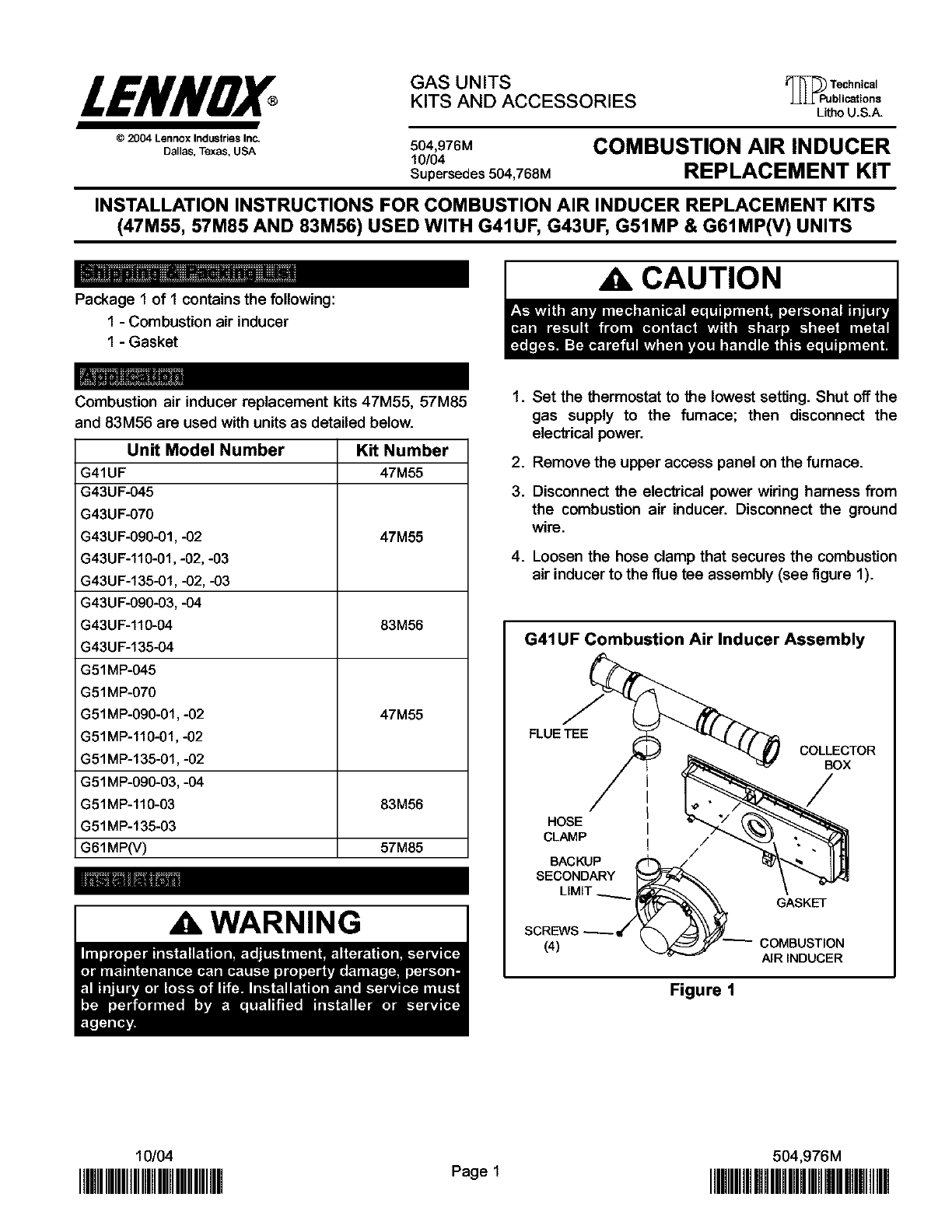
4. Loosen the hose clamp that secures the combustion
air inducer to the flue tee assembly (see figure 1).
G41UF Combustion Air Inducer Assembly
FLUE TEE
I
HOSE I
CLAMP ! /
BACKUP ("_,=_ /
SECONDARY
LIMIT __
SCREWS
COLLECTOR
BOX
GASKET
COMBUSTION
AIRINDUCER
Figure 1
10/04 504,976M
I]IMII]IIIMIMIIIIIIIIII Pogel IIMIIflMMMH
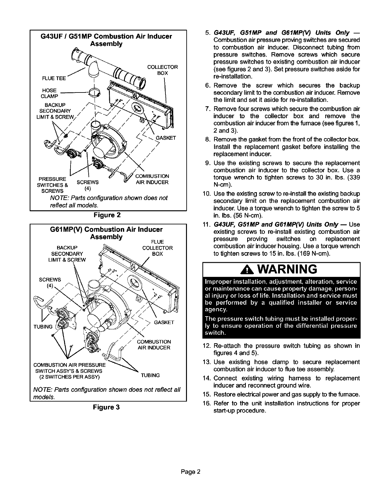
G43UF /G51MP Combustion Air Inducer
Assembly
FLUE TEE j
HOSE
CLAMP "_
BACKUP /_'t_
SECONDARY / I
LIMIT & SCREW//
COLLECTOR
BOX
/
/
/
PRESSURE SCREWS AIR INDUCER
SWITCHES &
SCREWS (4)
NOTE: Parts configuration shown does not
reflect all mode/s.
Figure 2
G61MP(V) Combustion Air Inducer
Assembly FLUE
BACKUP COLLECTOR
SECONDARY BOX
LIMIT & SCREW
SCREWS
_GASKET
TUBING /
/ // /
_:_ /COMBUSTION
\ _ AIRINDUCER
(2SWITCHES PERASS_ TUBING
NOTE: Parts configuration shown does not reflect all
models.
Figure 3
5. G43UF, G51MP and G61MP(V) Units Only --
Combustion air pressure proving switches are secured
to combustion air inducer. Disconnect tubing from
pressure switches. Remove screws which secure
pressure switches to existing combustion air inducer
(see figures 2 and 3). Set pressure switches aside for
re-installation.
.
7.
Remove the screw which secures the backup
secondary limit to the combustion air inducer. Remove
the limit and set it aside for re-installation.
Remove four screws which secure the combustion air
inducer to the collector box and remove the
combustion air inducer from the furnace (see figures 1,
2 and 3).
8. Remove the gasket from the front of the collector box.
Install the replacement gasket before installing the
replacement inducer.
9. Use the existing screws to secure the replacement
combustion air inducer to the collector box. Use a
torque wrench to tighten screws to 30 in. Ibs. (339
N-cm).
10. Use the existingscrew to re-install the existing backup
secondary limit on the replacement combustion air
inducer. Use a torque wrench to tighten the screw to 5
in. Ibs. (56 N-cm).
11. G43UF, G51MP and G61MP(V) Units Only -- Use
existing screws to re-install existing combustion air
pressure proving switches on replacement
combustion air inducer housing. Use a torque wrench
to tighten screws to 15 in. Ibs. (169 N-cm).
iWARNING i
12. Re-attach the pressure switch tubing as shown in
figures 4 and 5).
13. Use existing hose clamp to secure replacement
combustion air inducer to flue tee assembly.
14. Connect existing wiring harness to replacement
inducer and reconnect ground wire.
15. Restore electrical power and gas supply to the fumace.
16. Refer to the unit installation instructions for proper
start-up procedure.
Page 2
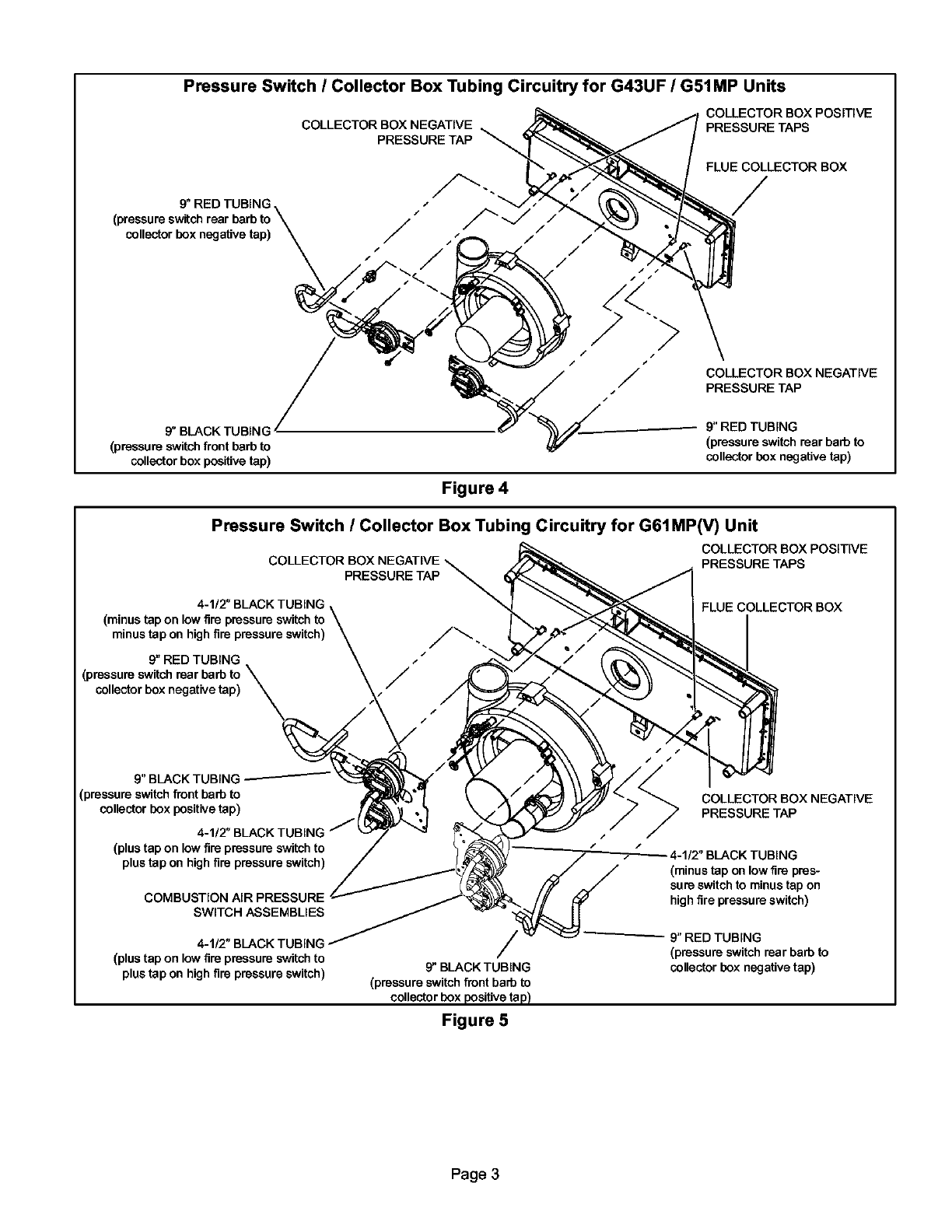
Pressure Switch /Collector Box Tubing Circuitry for G43UF /G51MP Units
COLLECTOR BOX NEGATIVE
PRESSURE TAP
COLLECTOR BOX POSITIVE
PRESSURE TAPS
FLUE COLLECTOR BOX
9" RED TUBING /
collector box negative tap) J
/
9" BLACK TUBING
(pressure switch front barb to
collector box positive tap)
Figure 4
/COLLECTOR BOX NEGATIVE
PRESSURE TAP
9" RED TUBING
(pressure switch rear barb to
collector box negative tap)
Pressure Switch ICollector Box Tubing Circuitry for G61MP(V) Unit
COLLECTOR BOX NEGATIVE \
PRESSURE TAP
4-1/2" BLACK TUBING
(minus tap on low fire
minus tap on high fire pressure switch) J_
9" RED TUBING ._
/
collector box negative tap) J
COLLECTOR BOX POSITIVE
PRESSURE TAPS
FLUE COLLECTOR BOX
9" BLACK TUBING
(pressure switch front barb to
collector box positive tap)
(plus tap on low fire pressure switch to
plus tap on high fire pressure switch)
COMBUSTION AIR PRESSURE
SWITCH ASSEMBLIES
4-1/2" BLACK TUBING
(plus tap on low fire pressure switch to
plus tap on high fire pressure switch) 9" BLACK TUBING
(pressure switch front barb to
collector box positive tap)
Figure 5
COLLECTOR BOX NEGATIVE
PRESSURE TAP
I/2" BLACK TUBING
(minus tap on low fire pres-
sure switch to minus tap on
high fire pressure switch)
9" RED TUBING
(pressure switch rear barb to
collector box negative tap)
Page 3
