LENNOX Furnace/Heater, Gas Manual L0806829
User Manual: LENNOX LENNOX Furnace/Heater, Gas Manual LENNOX Furnace/Heater, Gas Owner's Manual, LENNOX Furnace/Heater, Gas installation guides
Open the PDF directly: View PDF ![]() .
.
Page Count: 9
Technlc_J
® GAS KITS AND ACCESSORIES
©1993 Lennox Industries Inc.
Dallas, Texas
LJtho U.S., _
502,887M
7/93
Supersedes 502,583M GAS TWINNING KIT
INSTALLATION INSTRUCTIONS FOR TWINNING KIT, NON--CONTINUOUS FAN,
LB--63093B (64H88) USED WITH GAS FIRED FURNACES
Package 1 of I contains:
1- - Twinning control box with cover
2- -Auxiliary limit controls on mounting bracket
4-- #8 -- 18 screws
5-- Grommets
4- - 1/4" piggy back terminal connectors
5- - Dual male terminal connectors
Twinning kit and gas fired furnaces must be installed and
wired in accordance with local codes. Authorities having
jurisdiction should be consulted before installation. Refer
to NEC standard in the US or CEC standard in Canada
on all wire insulations and sizes.
Twinning kit (LB--63093B) is used for either single or
two--stage burner operation with simultaneous blower
operation. The two units must be of the same application:
upflow, downflow or horizontal. Furnaces must also be of
the same blower size. The heating speed taps on each
unit must be set the same. The cooling speed tap of one
unit must also be that same as the other unit. The control
system is designed for single or two- -stage heating and
single or two- -stage cooling.
NOTE--Air stratification problems may result from using
two stage heating with twinning kit.
This gas twin kit does not include the feature for
continuous low speed fan. A separate gas twinning kit
with that feature is available as part no. 35J93.
Installation of the gas twinning kit is in three parts. The
auxiliary limits are installed in each furnace. Next, the gas
twin control box is installed. Finally, the wiring is done to
complete the project.
A--Installing Auxiliary Limit Controls ($92)
Auxiliary limit controls (identified as $92 on wiring
diagram key charts) must be installed to provide
protection from overheating in case of blower failure.
Install auxiliary limits as described in the following
sections according to the application.
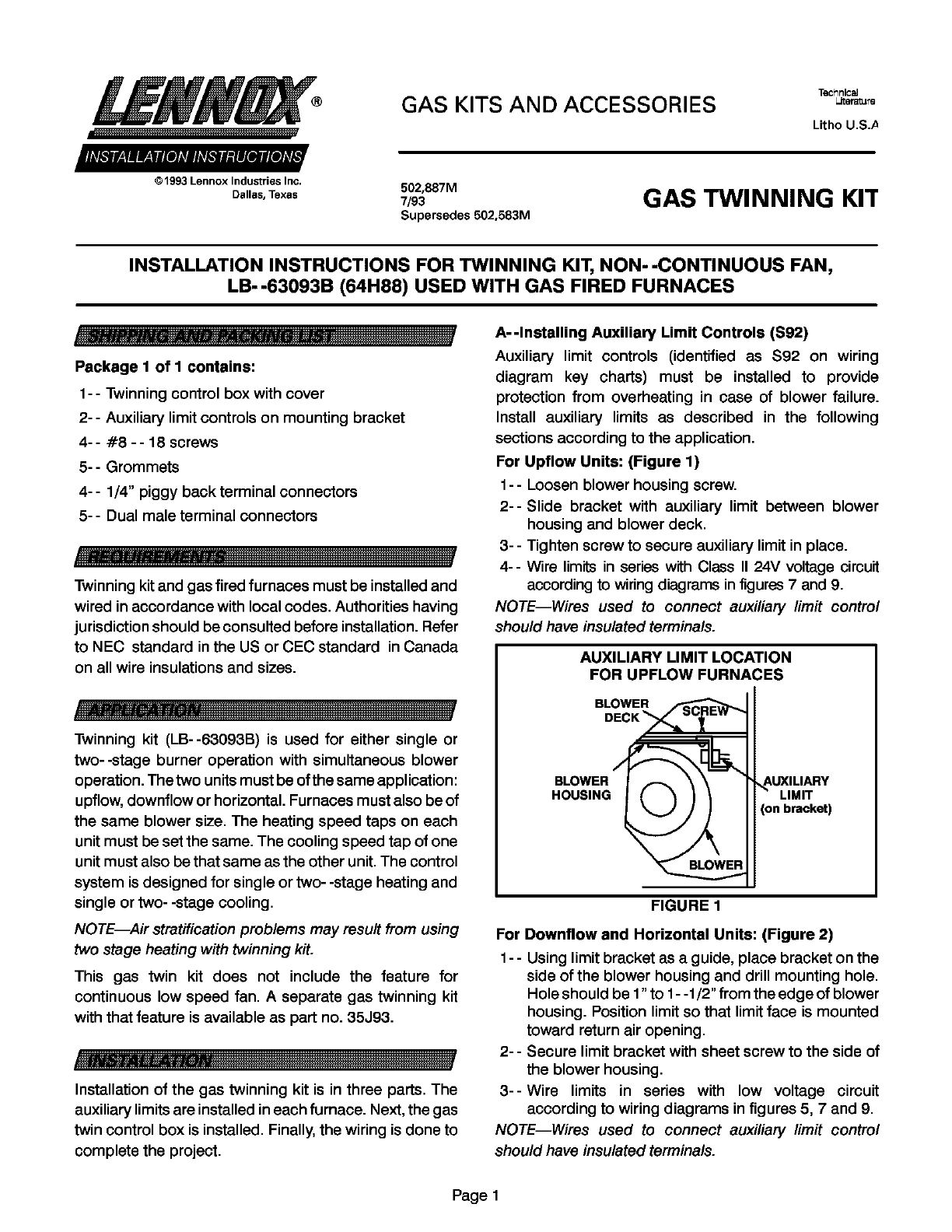
For Upflow Units: (Figure 1)
1- - Loosen blower housing screw.
2-- Slide bracket with auxiliary limit between blower
housing and blower deck.
3-- Tighten screw to secure auxiliary limit in place.
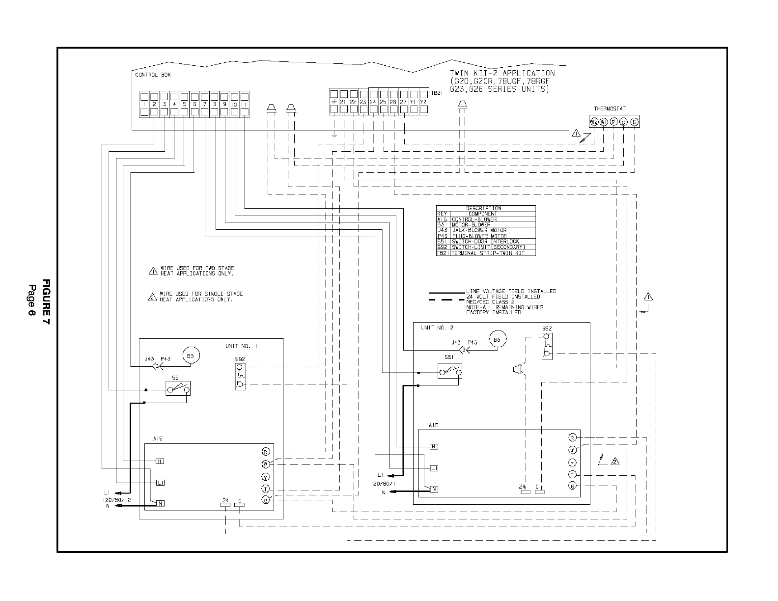
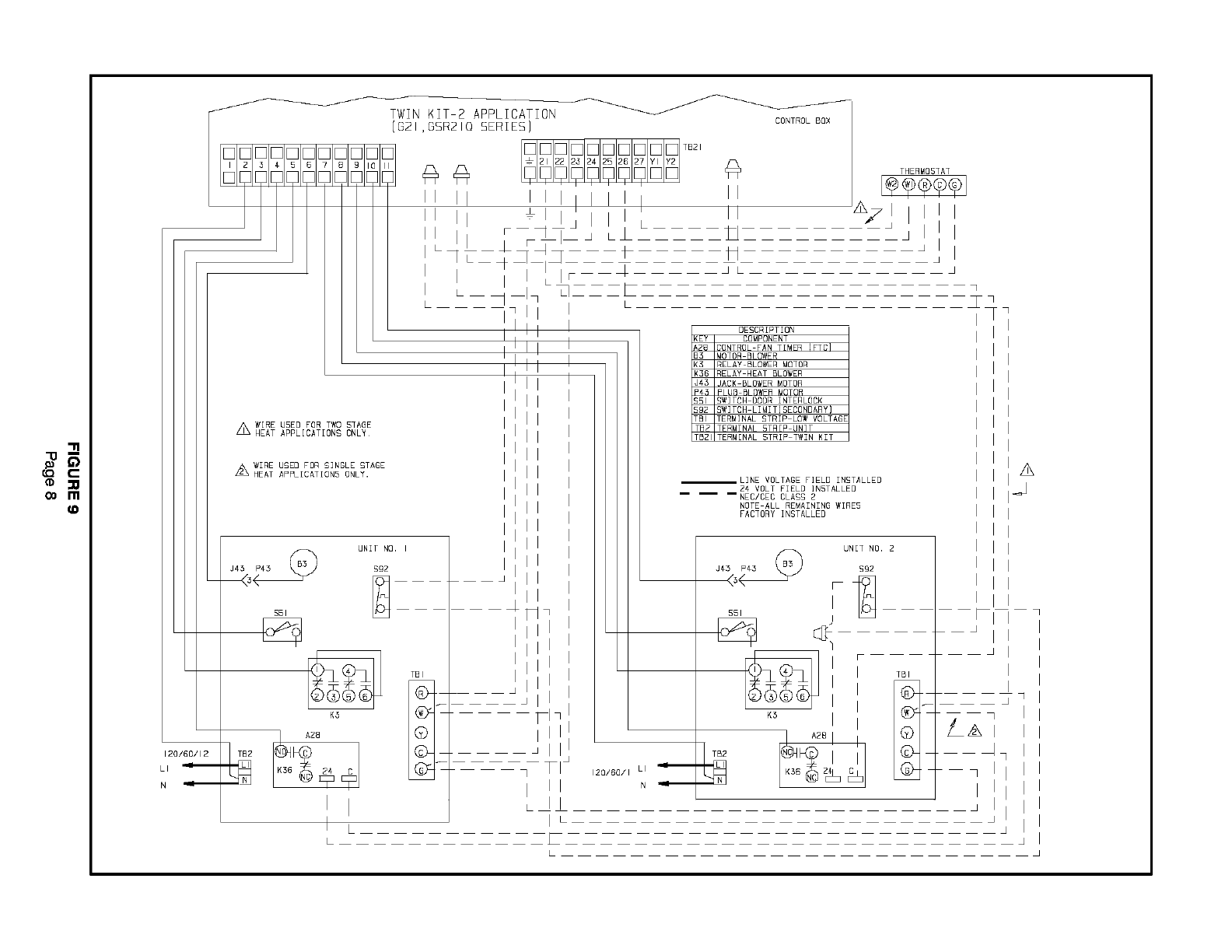
4-- Wire limits in series with Class II 24V voltage circuit
according to wiring diagrams infigures 7 and 9.
NOTE--Wires used to connect auxiliary limit control
should have insulated terminals.
AUXILIARY LIMIT LOCATION
FOR UPFLOW FURNACES
BLOWE R_F"_'_t2,. _
BLOWER
HOUSING _AUXlLIARY
LIMIT
(on bracket)
FIGURE 1
For Downflow and Horizontal Units: (Figure 2)
1- - Using limit bracket as a guide, place bracket on the
side of the blower housing and drill mounting hole.
Hole should be 1"to 1- -1/2" from the edge of blower
housing. Position limit so that limit face is mounted
toward return air opening.
2- -Secure limit bracket with sheet screw to the side of
the blower housing.
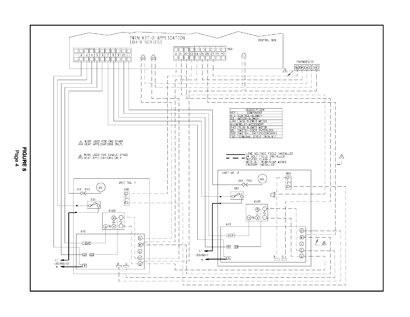
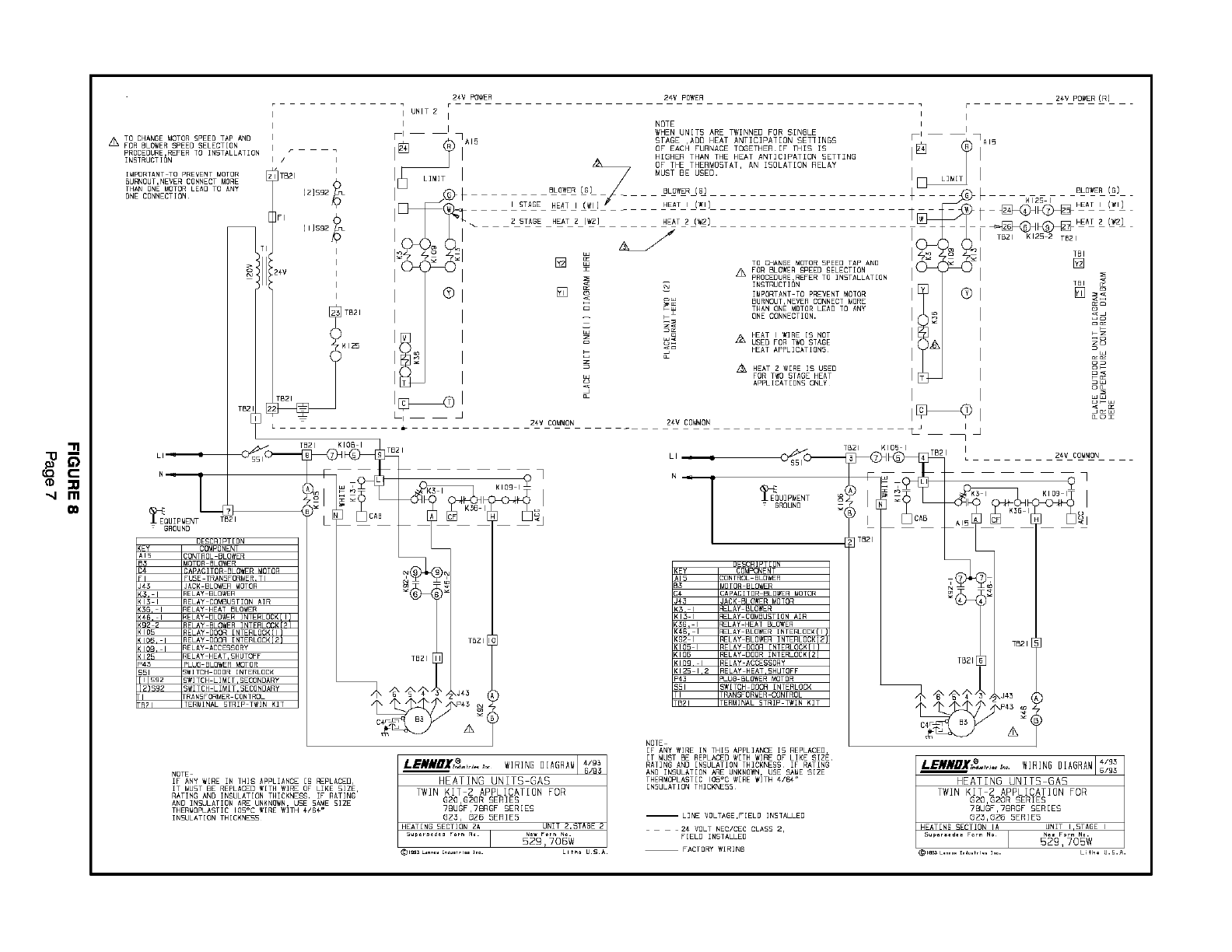
3--Wire limits in series with low voltage circuit
according to wiring diagrams in figures 5, 7 and 9.
NOTE--Wires used to connect auxiliary limit control
should have insulated terminals.
Page1
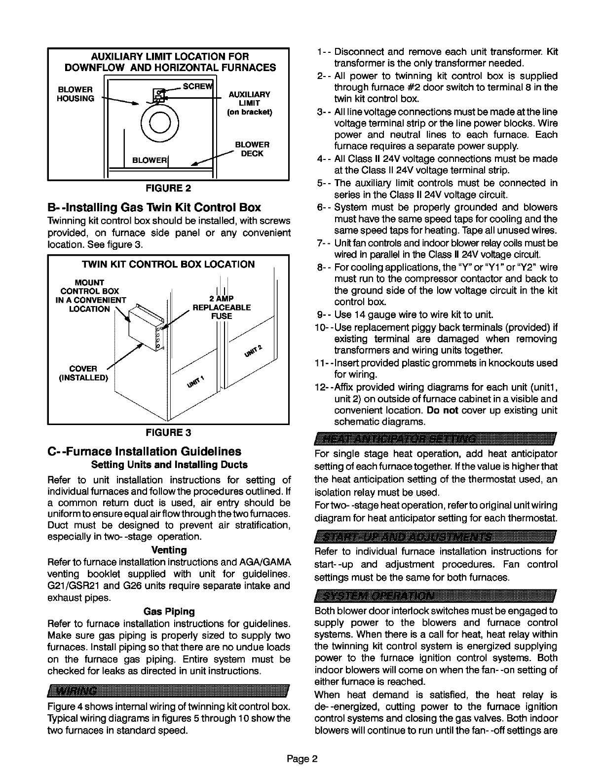
AUXILIARY LIMIT LOCATION FOR
DOWNFLOW AND HORIZONTAL FURNACES
BLOWER
HOUSING
_SCREW
BLOWER I
AUXILIARY
LIMIT
(on bracket)
BLOWER
IDECK
FIGURE 2
B--Installing Gas Twin Kit Control Box
Twinning kit control box should be installed, with screws
provided, on furnace side panel or any convenient
location, See figure 3,
TWIN KIT CONTROL BOX LOCATION
MOUNT II
CONTROL BOX I I
IN A CONVENIENT 2 AMP
LOCATION REPLACEABLE
FUSE
COVER
(INSTALLED)
FIGURE 3
C--Furnace Installation Guidelines
Setting Units and Installing Ducts
Refer to unit installation instructions for setting of
individualfurnaces and follow the procedures outlined. If
acommon return duct is used, air entry should be
uniform to ensure eq ualair flowthrough the two furnaces.
Duct must be designed to prevent air stratification,
especially in two- -stage operation.
Venting
Refer to furnace installation instructions and AGNGAMA
venting booklet supplied with unit for guidelines.
G21/GSR21 and G26 units require separate intake and
exhaust pipes.
Gas Piping
Refer to furnace installation instructions for guidelines.
Make sure gas piping is properly sized to supply two
furnaces. Install piping so that there are no undue loads
on the furnace gas piping. Entire system must be
checked for leaks as directed in unit instructions.
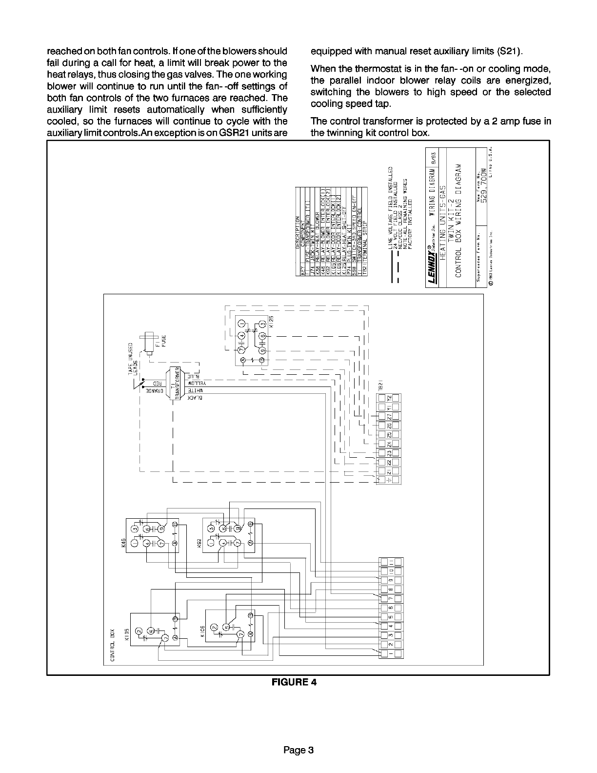
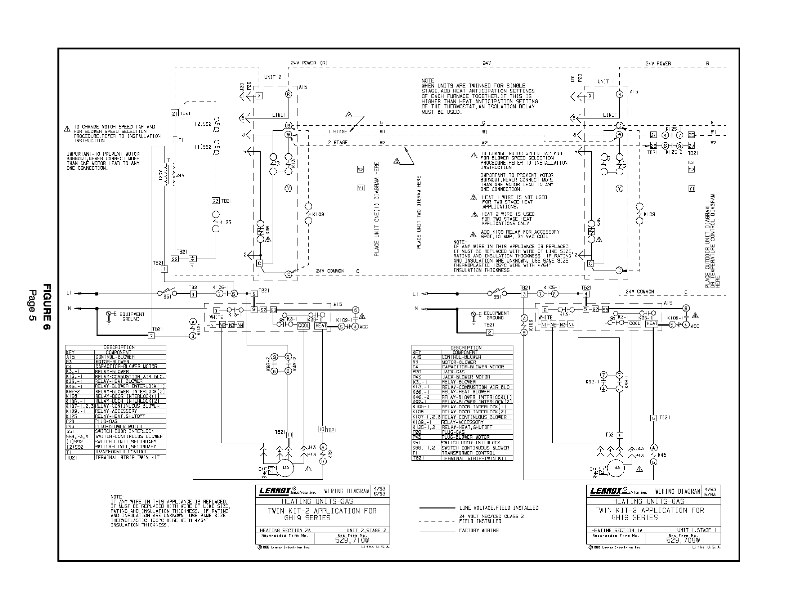
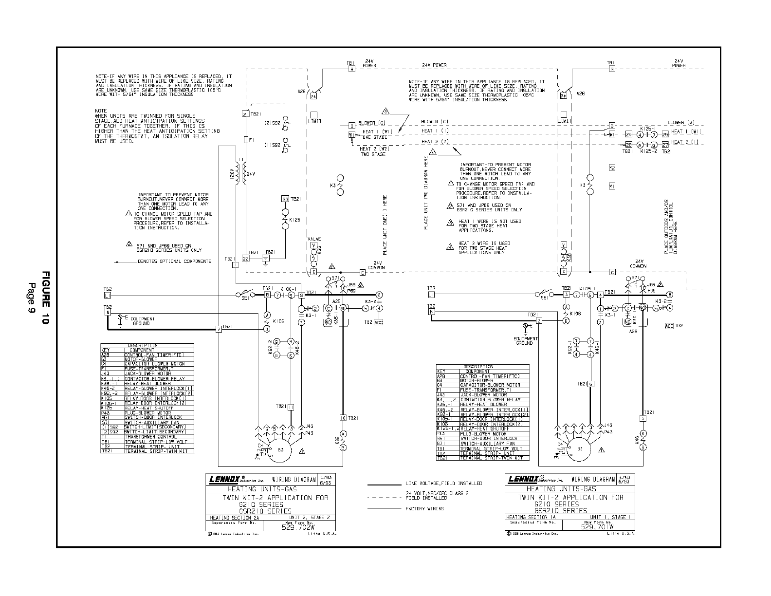
Figure 4 shows internal wiring of twinning kit control box.
Typical wiring diagrams in figures 5 through 10 show the
two furnaces in standard speed.
1-- Disconnect and remove each unit transformer. Kit
transformer is the only transformer needed.
2-- All power to twinning kit control box is supplied
through furnace #2 door switch to terminal 8 in the
twin kit control box.
3- - All line voltage connections must be made at the line
voltage terminal strip or the line power blocks. Wire
power and neutral lines to each furnace. Each
furnace requires aseparate power supply.
4-- All Class II 24V voltage connections must be made
at the Class II 24V voltage terminal strip.
5-- The auxiliary limit controls must be connected in
series in the Class II 24V voltage circuit.
6-- System must be properly grounded and blowers
must have the same speed taps for cooling and the
same speed taps for heating. Tape all unused wires.
7- -Unitfan controlsand indoorblower relaycoils must be
wired in parallel in the Class II 24V voltage circuit.
8- -For cooling applications, the "Y" or "Y1" or "Y2" wire
must run to the compressor contactor and back to
the ground side of the low voltage circuit in the kit
control box.
9- - Use 14 gauge wire to wire kit to unit.
10- - Use replacement piggy back terminals (provided) if
existing terminal are damaged when removing
transformers and wiring units together.
11- -Insert provided plastic grommets in knockouts used
for wiring.
12--Affix provided wiring diagrams for each unit (unit1,
unit 2) on outside of furnace cabinet in a visible and
convenient location. Do not cover up existing unit
schematic diagrams.
For single stage heat operation, add heat anticipator
setting of each furnace together. If the value is higher that
the heat anticipation setting of the thermostat used, an
isolation relay must be used.
For two- -stage heat operation, refer to original unit wiring
diagram for heat anticipator setting for each thermostat.
Refer to individual furnace installation instructions for
start--up and adjustment procedures. Fan control
settings must be the same for both furnaces.
Both blower door interlock switches must be engaged to
supply power to the blowers and furnace control
systems. When there is a call for heat, heat relay within
the twinning kit control system is energized supplying
power to the furnace ignition control systems. Both
indoor blowers will come on when the fan- -on setting of
either furnace is reached.
When heat demand is satisfied, the heat relay is
de--energized, cutting power to the furnace ignition
control systems and closing the gas valves. Both indoor
blowers will continue to run until the fan- -off settings are
Page 2
equippedwith manual reset auxiliary limits (S21).
reached on both fan controls. Ifone of the blowers should
fail during a call for heat, a limit will break power to the
heat relays, thus closing the gas valves. The one working
blower will continue to run until the fan--off settings of
both fan controls of the two furnaces are reached. The
auxiliary limit resets automatically when sufficiently
cooled, so the furnaces will continue to cycle with the
auxiliary limit controls.An exception is on GSR21 units are
When the thermostat is in the fan- -on or cooling mode,
the parallel indoor blower relay coils are energized,
switching the blowers to high speed or the selected
cooling speed tap.
The control transformer is protected by a 2 amp fuse in
the twinning kit control box.
2
< G
no _ <
_z_ iz
JJ z
ou,o _©
z u_u _
J_zz_ S
z
_D
8
2
L
DD
D_[1
-D_[:1
D_[1
D_[1
D_[1
D_[1
D_[1
D-J1
FIGURE 4
Page 3
"11
m
LI_
120/60/12
N_
DDDD
WIRE USED FOR TWO 5TABE
A HEAT ONLY.
APPLICATIONS
WIRE USED FOR SINGLE STAGE
A HEAT APPLICATION5 ONLY.
UNIT NO. I
5°2
• _ K 09
A,_ ii
II IIlllll
%11 I
II . ill
I r _ZI • LL
I I _lr 4
• I7 _IZZZ_
I I I L
I I I
I
I I
I
I
I
I
I
I
I
J
LI _
I I 120/60/I
N
1
LIJ
II
I
k
II
_Jwl I
J I
J L
DESCRIPTION
(EY COMPONENT
q5 ]ONTROL BLOWER
t3 _OTOR 6LO#ER
J#3 JACK BLOWER MOTOR
(109 qELAY ACCESSORY
_45 uLU6 BLOWER MOTOR
_51 5WITCH DOOR INTERLOCK
_92 5WITCH L[N[_(SECONDARYJ
621 ERMINAL 5TRIP T_IN KIT
,LINE VOLTAGE FIELD INSTALLED
24 VOLT FIELD INSTALLED
_ -- _NEC/CEC CLASS 2
NOTE ALL REMAINING WIRES
FACTORY INSTALLED
UNIT NO 2
J¢5 P45
551
AI5
_i_ NN
22N
$92
I
/
KIO£ I r
ill
JI
]
_2
1
• I
J
A
I
J
h
L
2¢V POWER (R] 24V 24V POWER R
I
I UNiT 2 I o
I NOTE _ _ I UNIT I I
WHEN UNITS ARE TWINNEB FOR SINGLE FI
mm
TO CHAN_E MOTOR SPEED TAP AND
FOR BLOWER SPEEB ELECTION
PROCEDURE,REFER TO INSTALLATION
INSTRUCTION
[_PORTANT TO PREVENT WOTOR |
6URNOUT,NEVER CONNECT MORE
i
THAN ONE _OTOR LEAD TO ANY
ONE CONNECTION. >
Q
LI J •
I o0ou.o
EOUIPMENT
=
UL_CHIHIIUN
KEY COMPONENT
AI5 gONTRBL 5LO_ER
_ MOTOR 5LBWER
R4 CAPACITOR BLGWER _OTOR
K3, I REL4Y BLOWER
KI3. I REL4Y COMSUSTION AIR 5LO.
K36, I RELAY HEAT BLOWER
K46, I RELAY BLOWER [NTERLOCKIIJ
K92 2 RELAY 5LO_ER INTERLGCK[2]
KI05 RELAY BOOR INTERLOCK(I]
<lOB, I RELAY BOOR [NTERLOCKI21
_I07 1 2 : RELAY CONTINUOUS BLOWER
KIBg. I RELAY ACCESSORY
KIP5 RELAY HEAT SHUTOFF
PPD PILIQ _AS
=#3 PLUG BLOWER MGTOR
£51 SWITCH DOOR INTERLOCK
S6B. 3.4 SWITCH CONTINUOUS BLOWER
111592 ,SECONDARY
(2)£92 S_[TCH LIM[TSECONDARY
TI TRAN£FORWER CONTROL
TB21 TERMINAL STRIP T_IN KIT
/•
I
'TB21
]rm 0
I
I
24v i
I
I
TBZI
_125
l=
NOTE
iF ANY _IRE IN THIS APPLIANCE iS REPLACEB.
IT MUST BE REPLACEB _ITH _[RE OF LIKE SIZE,
RATIN6 ANB INSULATION THICKNESS, IF RATING
4ND [NSUL4TION ARE UNKN_N_ USE SAME _IZE
THERMOPLASTIC I05_C _IRE _[TH _/64"
INSULATION THICKNESS
®
I i
I
I _ _ _ 24v COMMON
o
=z
U
o
BURNOUT,NEVER CONNECT MORE
THAN gNE _OTOR LEAB TO ANY
ONE CONNECTION.
HEAT I WiRE IS NBT USEB
FOR TWO STAGE HEAT
APPLICATIONS,
Z_ HE4T 2 WIRE IS USEB
FOR TWO STA6E HEAT
APPLICATION5 ONLY
,_, ADB KI09 RELAY FOR ACCESSBRY
£PBTIO AMP, 2_ V4C COIL
NOTE
q_
LI <J |
TOZI_ [
N
ANB INSULAT[gN ARE UNKNg'/_N, USE SAME SIZE
THERMOPLASTIC I05aC _[RE WITH 4/64"
[NSULATIGN THICKNESS_
G
WI
W2
--
uEounlrl_Ul_
mKEY COMPONENT
AI5 :ONTROL BLOWER
_qT_R RIn_FR
P2oC_:APAC[TOR?_I_ BLOWER _OTOR
P43 JACK 6LO_ER MOTOR
tELA¥ BLOWER
IKI05 I _EL4Y DOOR INTERLOCK[I] I
IKI05 _EL4Y DOOR INTERLOCK[Z] I
IKI07 I.Z.3 _FIAY CqNT_N[Jn[I_ _I_FR I
TB21 p20 'LUG 8AS
p¢3 'LUG 5LO_ER _OTOR
£51 ;_ITCH BOOR INTERLOCK
)_ _8 m2 ,WITCH CO,TINUGUS _LOWERR4NSFOR_ER CONTROL
) _ _FR_N_ _TRfP T_lN KfT
LiNE VOLTAGE,FIELB IN£TALLEB
24 VBLT NEC/CEC CLASS 2
F[ELB INSTALLEB
FACTBR¥ _IR[N8
G
WI
',_2
I ITB21
TB21[6]
_En_ ........ WIRINGBIAGRAMI#_#
i
HEATING UNITS GAS
TWIN KIT 2 APPLICATION FOR
GHI9 SERIES
HEAT[NB SECT[ON IA UNIT I.STAGE I
su_,_a_ ro,m No I
HEATING SECTION 2A UNiT 2,£TAGE 2
I
HEATING UNIT5 GAS
TWIN KIT 2 APPLICATION FOR
GHI9 SERIES
® []
_d
z_
o<
_ °_
mm
mc_
C
tQ
Ill
,,4
LI_
120/60/12
N_
E
WIRE U5EO FOR TWO 5TABE
,_x HEAT ONLY.
APPLICATIONS
WIRE U£ED FOR £INGLE £TABE
,_XHEAT APPLICATION5 ONLY.
551
AI5
II
II
I I
I I
I
I
I
UN[T NO. I
$92
k
h
L
II
Ij
I,
I
L
I L
I
I
I
LI
120/60/I
N _
TWIN KIT 2 APPLICATION
(G20,G20R,78UGF,78RGF
825,626 SERIES UNITS)
UNIT NO 2
i
II
II
ZI
J L
DESCRIPTION
(EY COMPONENT
_15 ]ONTROL BLOWER
t3 _OTOR BLOWER
J#3 JACK BLGWER MOTOR
"45 uLU8 BLOWER MOTOR
;51 3WITCH BOOR INTERLOCK
_92 _W[TCH L[N[TISECONDARY }
B21 ERMINAL STRIP TWIN KIT
,LINE VOLTAGE FIELD INSTALLED
24 VOLT FIELD INSTALLED
_ -- _NEC/CEC CLASS 2
NOTE ALL REMAINING WIRES
FACTORY INSTALLED
$51 I
I
I
I
AI5 I
I
I
I
:;;;;[A]
$92
I
I
i I
J
J
1
_2
I
I
I
1
• I
J
A
_J
I
J
2_V POWER 24V POWER
• i
I UNIT 2 i
II
m -11
"4 m
co
I
TO CHANGE MOTOR SPEEO TAP ANO I
FOR BLOWER SPEED SELECTION i
PROCEDURE,REFER TO ]N£TALLATiON _ •
[NSTRUCTIQN I /
IMPORTANT TO PREVENT MOTOR
BURNOUT,NEVER CONNECT MORE
THAN ONE MOTOR LE4B TO ANY
ONE CONNECTION_
T I
I
2#V I
I
I
[_ T521
KI25
(EY COMPONENT
AI5
_3 _OTOR BLOWER
:4
=i FUSE TRANSFOR_ER.TI
J43
_EL4Y BLOWER
(36, I _ELAY HEAT BLOWER
1g2(462 _IELAY BLO_R ]NTERLOCK I
(I05 _FIA¥ nn_R TNTFRInCK_II
{ 06 _ELA¥ DOOR [NTERLOCK_
_IELAY ACCE££QRY
(I_ _ELAY NEAT.SHUTOFF
_51 _ITCH BOOR INTERLOCK
_WITCH LI_[T£ECONDARY
(2)$92 S_[TCH LIMIT.SECONOARY
RANSFORMER CONTROL
NOTE
IF ANY WIRE IN THIS APPLIANCE [£ REPLACEO,
IT _UST BE REPL4CED _[TH _IRE gF LIKE SIZE_
RATING AND [N£ULATION THiCKNES£_ IF RATING
ANB INSULATION 4RE UNKNOWN, USE 5A_E SIZE
TNER_QPLAST[C IQ5°C _[RE _]TH _/6#"
[NSUL4TION THICKNESS
BLOWER (8]
NOffE
WHENUNITS ARE TW[NNEO FOR SINGLE
STAGE ,ADO HEAT ANTICIPATION SETff[NGS
OF EACH FURNACE TOGETHER IF THIS IS
HIGHER THAN THE NEAT ANTICIPAffION SETTING
OF THE THERMOSTAT, AN ISOLATION RELAY
MUST BE U£EO,
BLOWER IG)
NE4T I(Wl]
®1
L I •
2 STAGE HEAT 2 iW2]
[]!
<
INSTRUCTION
-- INPORTANT TO PREVENT NOTOR
_ow BURNOUT¸ NEVER CONNECT _ORE
_ THAN ONE _BTOR LEAD TO ANY
QNE CONNECTiQN.
NEAT I WIRE IS NOT
USED FOR TWO STAGE
NEAT APPLICATIONS¸
NEAT 2 WIRE ]S USEO
FOR TWO STAGE HEAT
4PPLICAT[ONS ONLY
2_V COMNON 24V COMMON
I
LI j
UL_CHIHILUN
KLY UUMHUNLNI
AI5 ]ONTROL BLOWER
B3 _nTnR RI_WFR
C_ SAPACITgR BLOWER _OTOR
J_3 lACK BLQWER NOTOR
K3, I ELAY BLQ_ER
KI3 I ELAY CO_BU£TION AiR
K36, I IELA¥ HEAT BLOWER
K¢6, I _ELA_ BLOWER INTERLOCK[I]
I_LAT _LU_H _NILHLUgKIZi
_ELAY O00R INTERLOCK[I]KI05 I
IELAY DOOR INTERLOCK[2]
IELA¥ ACCE££OR¥
KI25 1,2 _ELA¥ HEAT,SHUTOFF
p¢3 'LUG BLOWER MOTOR
551 _W[TCH DOOR INTERLOCK
TI RANSFOR_ER CONTROL
TB21 ERMINAL £TRiP TWIN KiT
I ° 1....I
_.ENNBX,_,,,.,_ WIRING BIAGfiA_6/£_
HEATING UNITS GAS
TWIN KIT 2 APPLICATION FOR
G20,G2QR SERIES
78UGF 78RGF £ERIE£
625, 826 SERIES
NOTE
IF ANY WIRE IN THI£ APPLIANCE [£ REPLACED,
IT _UST BE REPLACED WITH _IRE OF LiKE SIZE_
RATING AND INSULATION TNiCKNE££_ iF RATING
ANB ]NSULAT[QN ARE UNKNQ_N, USE SA_E SIZE
TNER_OPLA£T[C 105°C WIRE _ITH _/6_ _
INSULATION THiCKNES5_
I LINE VOLT4GE,FIELO INSTALLEO
24 VOLT NEC/CEC CL4SS 2,
FIELD INSTALLED
FACTORY _IRINB
I
2_V POWER (R)
I I
I_ @1
I ..... I
_ _ BLOWER (8)
_ KI25 I
T_ _t _ ..... (91)
I T51 _
$=
X_
=W
u_m
_mm
HEATING UNITS GAS J
TWIN KIT 2 APPLICATION FOR
G2Q,G20R SERIES
78UBF78RGF SERES
_TO_SIO_6 5ERIE5
"11
t,Q
co m
120/60/12
LI
N
E
WIRE U5EO FOR TWO 53AOE
Z_ HEAT APPLICAT[ONS ONLY
WIRE U£EO FOR £INGLE £TAGE
Z_HEAT APPL[CA_[0N5 ONLY.
UN[T NO I
551
L
I
Ill IIl_ I I
I II +II I I
I
L I
I
I
I
I
I
TBI I
iii
=II
• FI
II
L II
I'
t
I L
I
I
I
120/6Q/I LI
N _
THERMOS_A_
jill
• • J
DE£CR[PTION
IEY COMPONENT
t28 ZONTROL FAN TIMER (F3CI
53 _O_OR BLOWER
(3 RELAY BLOWERMOTOR
<36 qELAY NEAT 6LOWER
J43 JACK BI nWFR MOTOR
=43 PlUG 61nWFR MOTOR
_51 £WITCN DOOR INTERLOCk
592 SWITCH LIMIT(£ECONOARY I
[BI TERMINAL STRIP LOW VOLTAGE
TB2 TERMINAL 5TRIP UNIT
TO21 TERMINAL STRIP TWIN KIT
LINE VOLTAGE FIELD IN£TALLED
Z4 VOLT FIELD IN5TALLED
NEC/CEC CLA££ 2
NOTE ALL REMAININO WIRE5
FACTORY INSTALLED
551
K3
A
I
• I
J
J
_0
NOTE IF ANY WIRE IN THIS APPLIANCE [5 REPLACEB, IT
MUST BE REPLACED WITH WIRE OF LIKE £12E, RATING
AND INSULATION THICKNESS. IF RATIN6 AND INSULATION
ARE UNKNOWN, USE SAME SIZE THERMOPLASTIC 105°C
WIRE WITH 5/6_ _ INSULATION THICKNESS
NOTE
WHEN UNITS ARE TWINNED FOR S[NGLE
STAGE,ADD HEAT ANTiCiPATiON £E_TING£
OF EACH FURNACE TOGETHER iF THIS IS
HIBHER THAN THE HEAT ANTiCiPATiON SE_TIN8
OF THE THERMOSTAT, AN ISOLA_[ON RELAY
_UST BE USED.
IMPORTANT TO PREVENT _OTOR
BURNOUT,NEVER CONNECT _ORE
THAN ONE MOTOR LEAD TO ANY
ONE CONNECTION.
_TO CHANGE MOTOR SPEED TAP AND
FOR 5LBWER SPEED SELEgTIBN
PROCEDURE,REFER TO [NSTALLA
TION [NSmUgTION.
._ 571 AND JP69 USED ON
GSR21B SERIES UNITS ONLY
--DENOTE50PT[BNAL COMPBNENTS
OLBCHIHIION
KEY COMPONENT
APA :ONTRnl FAN T_MFR(FTC]
B3 IOTOR BLOWER
C_ :APACITOR BLOWER _OTOR
FI USE TRANSFORMER.TI
J_ JACK BLOWER HOTDB
K_ I _ _nNTACTBR RIO_FR RFIAY
_6 I _EL_Y HEAT BLB_ER
K_6 2 _ELAY 5LB_ER [NTERLOCKfll
K92. 2 ]Flay _IN_FR TNTFRIBC_I_I
KI05 _FIAY BOOR _NTFRIBCKII]
KI06 I _ELAY DOOR [NTERLOCK[21
KI25 ]ELAY HE_T 5HUTBFF
p¢_ _LU6 BLOWER MOTOR
351 _ITCH BOBR INTERLOCK
71 _TCH ALIX_I TARY FAN
s,l_g__ITOHLIMITSEOONO_RYJ
I_Sg2_ITC.L_MIT/SECO.DARY,
TI mANSFORMER CONTROL
TBI FR_TN_I STRIP I_ Wl T
TB2 fERM[N_L STRIP UNIT
o
TB I 2_V
A28
F 7
(z)sgz
]FI
2_V
HEAT 2 (W2]
TWO STAGE
K_
Z
o
5
W
<
2€v
COMMON
,J69_
_69
TB21
_J_5
2_V POWER TB I
NOTE IF ANY WIRE ]N TH[_ APPLIANCE IS REPLACED' ]T i A28_
_UST BE REPLACED WITH _[RE OF LIKE SIZE_ RATIN8
AND INSULATION THICKNESS. IF RATING AND IN£ULATIBN
_RE UNKNOWN, USE SAME SIZE THERMOPLAST[g 105og
_]RE _[TH 5/64 _ INSULATION THICKNESS I I
2_V
POWER
BLOWER (G)
HEAT I (I)
HEAT2 (2)
w[_PORTANT TO PREVENT _OTOR
BURNOUT, NEVER CONNECT MORE
i THAN ONE _OTOR LEAO TO ANY
ONE CONNECTION
A TO CHANOE _OTOR SPEED TAP AND
o FOR BLOWER £PEEO SELECTION
PROCEDURE,REFER TO ]NSTALLA
T]ON [NSmUCTION
w
_° Z_ HEAT I WIRE IS NOT USEO
FOR T_O £TAOE HEAT
APPLICATIONS.
Z_ HEAT 2 WIRE [£ U£EO
FOR TWO STARE HEAT
APPLICATIONS ONLY
TB2
[]
TB2
4 I
K3
_EY
_P8
:I
J_
{_, 1,2
1_6. 2
t92 I
11o5 I
11o6
351
f51
TB21
KI25 I BLOWER (B]
4_}K_aFOq_ HEAT_mq
TB21 KI25 2 TB21
[]
[]
24V
COMMON
z_
<zo
o_w
o_w
ww_
Jw_
b_H
_'_ _/ '_.......i_¢_
A28
EOU]PMEN 7
CONTROl FAN TT_FR[FTC]
MOTOR BLOWER TB21
CAPAC]TOR BLOWER MOTOR 6
FUSE TRANSFSR_JER,TI
JACK BLOWER _OTOR
CONTACTOR BLOWER RELAY
RELAY HEAT BLOWER
RELAY BLOWER INTERLOCK[ I]
RFI _Y RI nWFR [NTFRI nCKtP)
RELAY DOOR iNTERLOCK[ I]
RELAY BOOR INTERLOCK[21 %/_, _J43
RELAY HEAT SHUTOFF
PLU6 BLOWER _OTOR _4_: ¢'
£_ITCH BOOR INTERLOCK _ •
SWITCH AUXILIARY FAN
TERMINAL STRIP LOW VDLT _
TERMINAL STRIP UNIT
TERMINAL STRIP T_[N K]T
,J69_
,p69 L
_TB2
B21
iznnx_ I _'_ i
T_IN KIT 2 APPLICATION FOR
G21O SERIES
OGR210 SERIES
HEATING SECTION 2A UNIT 2, STAGE 2
529,702W
-- LINE VOLTAOE,F[ELO INSTALLED
2_ VOLT,NEC/CEC CL_££ 2
F]ELD [NSTALLEO
FACTBR¥ _]R[NG
I ° I....I
HEATING UNITS GAS
TWIN KIT 2 APPLICATION FOR
G21Q SERIES
GSR2 I0 SERIES
HEATING SECTION A UNIT STAGE P
@lgga Le.*o, I.a.,trl_. [*_ Li fhe U S,A,
