LENNOX Furnace/Heater, Gas Manual L0806908
User Manual: LENNOX LENNOX Furnace/Heater, Gas Manual LENNOX Furnace/Heater, Gas Owner's Manual, LENNOX Furnace/Heater, Gas installation guides
Open the PDF directly: View PDF ![]() .
.
Page Count: 2
GAS KITS
AND ACCESSORIES
11-9269
©1999 Lennox _ndustfiesInc 05/99
Supersedes 01/97
Dallas, Texas
iF TechnICal
IPublications
Litho USA
HEAT EXCHANGER REPLACEMENT KITS
INSTALLATION INSTRUCTIONS FOR HEAT EXCHANGER REPLACEMENT KITS
kWARNING
Package 1of 1contains:
1 - Heat exchanger assembly, including:
1 - flue box assembly
1 - pressure switch
1 - limit control
I - Plastic bag
1 - Conversion sticker
2- Wire nuts
2 - Wire ties (one of the screw-securing type, one plain)
1 - 4 in flue adapter for the 75 model size only
I - Installation instructions
Check all components for shipping damage. If any dam-
age is found, immediately contact the last carrier.
These kits are for use with the dash 1 and dash 2 ver-
sions of the 80MGF and G24M-45/60/75 series gas fur-
naces. In these units, they replace the existing heat ex-
changer with the current production heat exchanger,
thereby preventing nuisance flashback (burnback) in the
burners, as well as sooting of the heat exchanger. Refer
to table 1 for heat exchanger kit application.
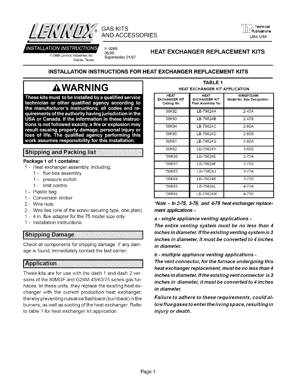
TABLE 1
HEAT EXCHANGER KIT APPLICATION
HEAT HEAT 80MGF/G24M
EXCHANGERK_ EXCHANGERK_ ModelNo. Size Design_ion.
Catalog No. FinalAssemblyNo,
38K92 LB-79824A 2-45A
38K93 LB-79824B 2-45S
38K94 LB-79824C 2-60A
38K95 LB-79824D 2-60S
36K61 LB-79824G 3-60A
36K62 LB-79824H 3-60S
"38K96 LB-79824E 2-75A
"38K97 LB-79824F 2-75S
"36K63 LB-79824J 3-75A
"36K64 LB-79824K 3-75S
"36K65 LB-79824L 4-75A
"36K66 LB-79824M 4-75S
*Note -In 2-75, 3-75, and 4-75 heat exchanger replace-
ment applications -
a-single appliance venting applications -
The entire venting system must be no less than 4
inches in diameter. If the existing venting system is 3
inches in diameter, it must be converted to 4 inches
in diameter.
b-multiple appliance venting applications -
The vent connector, for the furnace undergoing this
heat exchanger replacement, must be no less than 4
inches in diameter. If the existing vent connector is 3
inches in diameter, it must be converted to 4 inches
in diameter.
Failure to adhere to these requirements, could al-
Io wflue gases to enterthe living space, resulting in
injury or death.
Page 1
1- Beforebeginningtheinstallation,verifythatthemodel
numbersizedesignationindicatedonthereplacement
heatexchanger'sI.D.Iabelmatchesthatofthemodel
numbersizedesignationindicatedontheunifsrating
plate.Seetable1.
2- Setthethermostatto itslowestsetting.
3- Turn off all electrical power to the furnace.
4- Turn off the gas at the equipment main manual
shut-off valve.
5 - Remove the fumace access panel.
6 - Close the fumace gas valve.
7- Disconnect the supply gas line at the furnace gas
valve.
8 - Disconnect the wire harness and the ignition lead
from the ignition control.
9 - Disconnect the flue adapter with attached vent connec-
tor from the induced draft blower.
10 -Remove the heat exchanger assembly, with flue
box and burner box assemblies, from the unit.
11 - On the existing heat exchanger, cut the screw-secured
wire tie attached to the burner box top.
12 -Cut the induced draft blower leads between the
plug and the inducer leaving approximately 9 inch-
es (150mm) attached to the plug.
13 - Labeland then disconnect alIwiring from the burn-
er box to the limit control and pressure switch.
14 - Remove the burner box assembly from the exist-
ing heat exchanger and then install it in the re-
placement heat exchanger. Discard the existing
heat exchanger or return it to Lennox for a warran-
ty claim.
15 -On the replacement heat exchanger, using the
screw-securing type of wire tie (kit-provided), in
the original wire bundling location, bundle up all of
the Ioosewires, including the induced draft blower
leads. Do not secure the wire tie to the burner box
top at this time.
16 - Reconnect the limit control wires and the pressure
switch wires.
17 - Install the replacement heat exchanger in the cabinet.
18 - Splicethe induced draft blower leads using the kit-
provided wire nuts.
19 - Reconnect the wire harness and the ignition lead.
20 -Check the final wire routing, and then fasten the
screw-securing type of wire tie to the burner box
top, and bundle the remaining wires with the kit-
provided wire tie (plain-type).
21 - In 2-75, 3-75, and 4-75 heat exchanger replacement
applications -
a - single appliance venting applications -
The entire venting system must be no less than
4 inches in diameter. If the existing venting sys-
tem is 3 inches in diameter, convert itto 4 inches
in diameter.
b - multiple appliance venting applications -
The vent connector, for the furnace undergoing
this heat exchanger replacement, must be no
less than 4 inches in diameter. If the existing
vent connector is 3 inches in diameter, convert
it to 4 inches in diameter.
Note -Failure to adhere to the requirements, in
section a or b above, could allow flue gases to en-
ter the living space, resulting in injury or death.
Install the kit-provided 4 in. flue adapter to the outlet of
the induced blower. Then connect the flue adapter
to the 4 in. vent connector.
22 - In 2-45, 2-60, and 3-60 heat exchanger replacement
applications -
Reconnect the existing flue adapterwith vent con-
nector to the outlet of the induced blower.
23 - Affix the conversion sticker adjacent to the rating
plate.
24 - Reconnect the gas supply line to the gas valve.
25 - Turn on the main manual gas shut-off valve.
Carefully check all gas piping connections for leaks.
IMPORTANT
ILCAUTION
26 -Start the furnace by following the procedures as
indicated in the "Unit Start-Up" section of the
installation instructionsprovidedwiththefurnace.
27 - Monitor unit operation, both start-up operation and at
least 15 minutes of running operation. Repeat this test
two more times. When the test is successful, set the
thermostat to its normal heat setting.
Page 2
