LENNOX Furnace/Heater, Gas Manual L0807032
User Manual: LENNOX LENNOX Furnace/Heater, Gas Manual LENNOX Furnace/Heater, Gas Owner's Manual, LENNOX Furnace/Heater, Gas installation guides
Open the PDF directly: View PDF ![]() .
.
Page Count: 4
LENNOX
(''2002Lennox IndustriesInc.
Dallas,Texas
GAS UNITS
KITS & ACCESSORIES
_Technical
Jt_ Publications
Litho U.S.A.
504,456M
1/2002 WIRING HARNESS
REPLACEMENT KIT
INSTALLATION INSTRUCTIONS FOR WIRING HARNESS REPLACEMENT KITS
USED WITH G26, GHR26, G32, GHR32 AND AM30 UNITS
Package 1 of I contains:
Harness assembly(ies) - quantity varies from 1 to 4
Wires - quantity varies from 0 to 3
1 - Patch plate
2 - #8- 18 X 1/2 screws
1 - Strain relief bushing
1 - Amp plug cap
1 - Foam plug (AM30 kit only)
These kits are used to replace wiring harness
assembly(ies) in units as outlined in table 1.
Unit Model Number Kit Number
G26 & 90UGF 23M24
G32 23M25
G32V 23M26
GHR26 23M27
GHR32 23M28
GHR32V 23M29
AM30 23M30
&,WARNING
WARNING
Units with Exception of AM30
1 - Disconnect power and gas supplies to the unit
2 - Remove unit access panels.
01/02
IIIIIIIdlllllllIIIIIlllllIIIIIllllllll
3 -
1 -
2 -
3 -
4 -
5 -
6 -
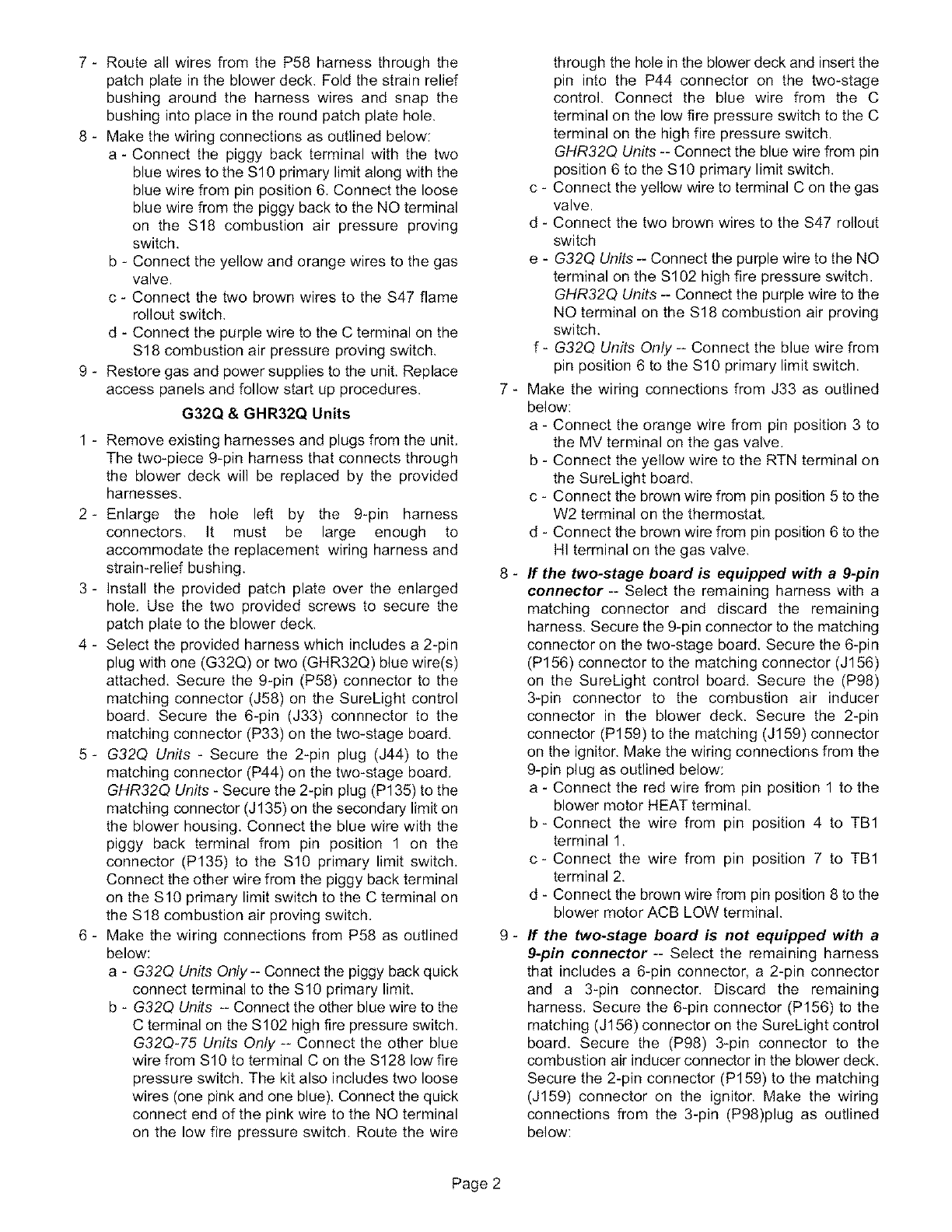
A,WARNING
/
DRIP LOOP
Identify existing wiring harness(es) to be replaced. If
the unit is equipped with harnesses routed through a
single strain relief bushing in the blower deck,
remove the existing harnesses and bushing. Route
replacement hamesses through the existing hole in
the blower deck and secure in place using the
provided strain relief bushing. Make wiring
connections per existing wiring diagram. Restore
gas and power supplies to the unit and follow start up
procedures.
G26, GHR26 & 90UGF
In many cases, these units are equipped with
separate harnesses that are connected by Molex
plugs in the blower deck. Remove these harnesses
and plugs from the unit.
Use the provided plug to fill the square hole left by the
three-wire combustion air inducer harness
connectors.
Enlarge the hole left by the nine-wire harness
connectors. It must be large enough to
accommodate the replacement wiring harness and
strain-relief bushing.
Install the provided patch plate over the enlarged
hole. Use the two provided screws to secure the
patch plate to the blower deck.
Secure the 9-pin (P58) and 6-pin (P156) harness
connectors to the matching connectors (J58 and
J156) on the SureLight control board.
Route the P84 and P159 two-wire harnesses from
the 6-pin (P156) harness through the patch plate in
the blower deck, Connect the P84 plug (black and
white wire) to the J84 jack on the combustion air
inducer motor. Connect the P159 plug (two white
wires) to the J159 jack on the electrode.
504,456M
IIIIIIIIIIIIIIIIIIIIIIIIIIIIIIIIItlllHlllllllll
7 - Route all wires from the P58 harness through the
patch plate in the blower deck, Fold the strain relief
bushing around the harness wires and snap the
bushing into place in the round patch plate hole.
8 - Make the wiring connections as outlined below:
a - Connect the piggy back terminal with the two
blue wires to the Sl 0 primary limit along with the
blue wire from pin position 6. Connect the loose
blue wire from the piggy back to the NO terminal
on the S18 combustion air pressure proving
switch.
b - Connect the yellow and orange wires to the gas
valve.
c - Connect the two brown wires to the S47 flame
rollout switch,
d - Connect the purple wire to the C terminal on the
S18 combustion air pressure proving switch,
9 - Restore gas and power supplies to the unit. Replace
access panels and follow start up procedures.
G32Q & GHR32Q Units
1 - Remove existing harnesses and plugs from the unit.
The two-piece 9-pin harness that connects through
the blower deck will be replaced by the provided
harnesses.
2-Enlarge the hole left by the 9-pin harness
connectors, It must be large enough to
accommodate the replacement wiring harness and
strain-relief bushing.
3 - Install the provided patch plate over the enlarged
hole. Use the two provided screws to secure the
patch plate to the blower deck,
4 - Select the provided harness which includes a 2-pin
plug with one (G32Q) or two (GHR32Q) blue wire(s)
attached. Secure the 9-pin (P58) connector to the
matching connector (J58) on the SureLight control
board. Secure the 6-pin (J33) connnector to the
matching connector (P33) on the two-stage board.
5- G32Q Units - Secure the 2-pin plug (J44) to the
matching connector (P44) on the two-stage board,
GHR32Q Units - Secure the 2-pin plug (P135) to the
matching connector (J 135) on the secondary limit on
the blower housing. Connect the blue wire with the
piggy back terminal from pin position 1 on the
connector (P135) to the Sl0 primary limit switch,
Connect the other wire from the piggy back terminal
on the SlO primary limit switch to the C terminal on
the $18 combustion air proving switch,
6 - Make the wiring connections from P58 as outlined
below:
a - G32Q Units Only-- Connect the piggy back quick
connect terminal to the SlO primary limit.
b - G32Q Units -- Connect the other blue wire to the
C terminal on the S102 high fire pressure switch,
G32Q-75 Units Only -- Connect the other blue
wire from SlO to terminal C on the S128 low fire
pressure switch. The kit also includes two loose
wires (one pink and one blue). Connect the quick
connect end of the pink wire to the NO terminal
on the low fire pressure switch. Route the wire
7 -
8 -
g -
through the hole in the blower deck and insert the
pin into the P44 connector on the two-stage
control. Connect the blue wire from the C
terminal on the low fire pressure switch to the C
terminal on the high fire pressure switch.
GHR32Q Units -- Connect the blue wire from pin
position 6 to the $10 primary limit switch.
c - Connect the yellow wire to terminal C on the gas
valve.
d - Connect the two brown wires to the S47 rollout
switch
e-G32Q Units -- Connect the purple wire to the NO
terminal on the S102 high fire pressure switch,
GHR32Q Units -- Connect the purple wire to the
NO terminal on the S18 combustion air proving
switch.
f - G32Q Units Only -- Connect the blue wire from
pin position 6 to the Sl0 primary limit switch.
Make the wiring connections from J33 as outlined
below:
a - Connect the orange wire from pin position 3 to
the MV terminal on the gas valve.
b - Connect the yellow wire to the RTN terminal on
the SureLight board,
c - Connect the brown wire from pin position 5 to the
W2 terminal on the thermostat.
d - Connect the brown wire from pin position 6 to the
HI terminal on the gas valve,
If the two-stage board is equipped with a 9-pin
connector -- Select the remaining harness with a
matching connector and discard the remaining
harness. Secure the 9-pin connector to the matching
connector on the two-stage board. Secure the 6-pin
(P156) connector to the matching connector (J156)
on the SureLight control board. Secure the (P98)
3-pin connector to the combustion air inducer
connector in the blower deck. Secure the 2-pin
connector (P159) to the matching (J159) connector
on the ignitor. Make the wiring connections from the
9-pin plug as outlined below:
a - Connect the red wire from pin position 1 to the
blower motor HEAT terminal,
b - Connect the wire from pin position 4 to TB1
terminal 1.
c- Connect the wire from pin position 7 to TB1
terminal 2.
d - Connect the brown wire from pin position 8 to the
blower motor ACB LOW terminal.
If the two-stage board is not equipped with a
9-pin connector -- Select the remaining harness
that includes a 6-pin connector, a 2-pin connector
and a 3-pin connector. Discard the remaining
harness, Secure the 6-pin connector (P156) to the
matching (J156) connector on the SureLight control
board. Secure the (P98) 3-pin connector to the
combustion air inducer connector in the blower deck.
Secure the 2-pin connector (P159) to the matching
(J159) connector on the ignitor. Make the wiring
connections from the 3-pin (P98)plug as outlined
below:
Page 2
a - ConnecttheblackwiretotheNOterminalonthe
Kll relayonthetwo-stageboard
b- ConnecttheredwiretotheNCterminalonthe
Kll relayonthetwo-stageboard.
c - Connecttheblackwirefrompinpositon4 onthe
6-pinconnector(P156)totheCterminalonthe
Kll relayonthetwo-stageboard.
10- Foldthestrainreliefbushingaroundthe harness
wiresandsnapthebushingintoplaceintheround
patchplatehole,
11- Restoregasandpowersuppliestotheunit.Replace
accesspanelsandfollowstartupprocedures.
G32V & GHR32V Units
1 - Remove existing harnesses and plugs from the unit,
The two-piece 9-pin harness that connects through
the blower deck will be replaced by the provided
harnesses,
2-Enlarge the hole left by the 9-pin harness
connectors. It must be large enough to
accommodate the replacement wiring harness and
strain-relief bushing.
3 - Install the provided patch plate over the enlarged
hole. Use the two provided screws to secure the
patch plate to the blower deck.
4 - Select the provided harness which includes a 6-pin
connector and a 9-pin connector; but. does NOT
include a 3-pin connector. Secure the 9-pin (P58)
connector to the matching connector (J58) on the
SureLight control board. Secure the 6-pin (J33)
connector to the matching connector (P33) on the
two-stage board,
G32V Units Only-- Secure the 2-pin plug (J44) to the
matching connector (P44) on the two-stage board.
5 - Route all remaining wires through the patch plate in
the blower deck.
6 - Make the wiring connections from P58 as outlined
below:
a - Connect the yellow wire to terminal C on the gas
valve.
b - Connect the two brown wires to the S47 rollout
switch
c - G32V Units -- Connect the purple wire to the NO
terminal on the S102 high fire pressure switch.
GHR32V Units -- Connect the purple wire to the
NO terminal on the S18 combustion air proving
switch,
7 - Make the wiring connections from J33 as outlined
below:
a - G32V Units -- Connect the blue wire from pin
position 1 to the C terminal on the S102 high fire
pressure switch.
G32V-75 Units Only -- Connect the blue wire
from pin position 1 to the C terminal on the S128
low fire pressure switch.The kit includes two
loose wires (one pink and one blue). Connect the
quick connect end of the pink wire to the NO
terminal on the low fire pressure switch. Route
the wire through the hole in the blower deck and
insert the pin into the P44 connector on the
two-stage control, Connect the blue wire from
the C terminal on the low fire pressure switch to
the C terminal on the high fire pressure switch.
GHR32V Units -- Connect the blue wire from pin
position 1 to the C terminal on the S18
combustion air proving switch.
b - Connect the orange wire from pin position 3 to
the MV terminal on the gas valve.
c - Connect the yellow wire from pin position 4 to the
RTN terminal on the SureLight board,
d - Connect the brown wire from pin position 6 to the
HI terminal on the gas valve,
8 - If the two-stage board is equipped with a 9-pin
connector -- Select the remaining harness that
includes a 9-pin connector. Secure the 9-pin
connector to the matching connector on the
two-stage board. Secure the 6-pin (P 156) connector
to the matching connector (J156) on the SureLight
control board. Secure the 3-pin (P98) connector to
the combustion air inducer connector in the blower
deck. Secure the 2-pin connector (P159) to the
matching (J159) connector on the ignitor.
9 - If the two-stage board is not equipped with a
9-pin connector -- Select the remaining harness
that includes a 6-pin connector, a 2-pin connector
and a 3-pin connector, Secure the 6-pin connector
(P156) to the matching (J156) connector on the
SureLight control board. Secure the 2-pin connector
(P159) to the matching (J159) connector on the
ignitor. Secure the 3-pin (P98) connector to the
combustion air inducer connector in the blower deck.
Make the remaining wiring connections from the
3-pin (P98)plug as outlined below:
a - Connect the black wire to the NO terminal on the
Kll relay,
b - Connect the red wire to the NC terminal on the
Kll relay,
c- Connect the black wire from J156 pin 4 to C
terminal of the Kll relay on the two-stage board
10 - Select the provided harness which includes a 15-pin
plug, Discard the remaining harness. Secure the
15-pin (J73) connector to the matching connector
(P73) on the VSP blower control board.
11 - Make the wiring connections from J73 as outlined
below:
a - Connect the piggy back connector on the blue
wire from pin position 1 to terminal C on the TB1
terminal block, Connect the other end of the blue
wire to terminal C on the SureLight control board,
b - Connect the piggy back connector on the green
wire from pin position 2 to the G terminal on the
TB1 terminal strip. Connect the other end of the
green wire to the G terminal on the SureLight
control board.
c - Connect the brown wire from pin position 3 to the
W2 terminal on the TB1 terminal strip. Connect
the other end of the brown wire into pin position
5 on the 6-pin (J33) connector on the two-stage
control board,
Page 3
d - Connectthepurplewirefrompinposition4tothe
DSterminalontheTB1terminalblock,
e- G32VUnits -- Route the blue wire from pin
position 5 through the hole in the blower deck,
Connect the wire to the S 10 primary limit switch.
GHR32V Units -- Secure the 2-pin (P135)
connector to the matching connector (J135) on
the secondary limit switch on the blower housing.
Connect the blue wire from pin position 1 of P135
to the S1O primary limit switch.
f-Connect the blue wire from pin position 6 to the
R terminal on the TB1 terminal block.
g - Connect the black wire from pin position 13 to the
R terminal on the SureLight control board. Route
the existing wire from the R terminal on the
SureLight control board through the hole in the
blower deck. Connect this wire to the Sl0
primary limit switch.
h - Connect the orange wire from pin position 15 to
the MY terminal on the gas valve,
12 - Fold the strain relief bushing around the harness
wires and snap the bushing into place in the round
patch plate hole,
13 - Restore gas and power supplies to the unit, Replace
access panels and follow start up procedures.
AM30
The unit may be equipped with two 3-pin harnesses
joined by connectors at the blower deck. Remove existing
harnesses and plugs from the unit, The two-piece 3-pin
harness that connects through the blower deck will be
replaced by the provided longer wires.
1-Disconnect power and gas supplies to the unit
2 - Remove unit access panels.
3 -
4-
5-
Enlarge the hole left by the 9-pin harness
connectors. It must be large enough to
accommodate the replacement wiring harness and
strain-relief bushing.
Install the provided patch plate over the enlarged
hole. Use the two provided screws to secure the
patch plate to the blower deck,
Connect stripped end of provided black wire to wire
nut in pump housing and connect quick connect
terminal to PUMP terminal on AM30 control board.
6 - Connect stripped end of provided white wire to wire
nut in pump housing and connect quick connect
terminal to NEUTRAL terminal on AM30 control
board.
7- Connect stripped end of provided green wire to
screw terminal on pump and screw terminal on
transformer.
8 - Restore gas and power supplies to the unit. Replace
unit access panels and follow start up procedures.
Page 4
