LENNOX Furnace/Heater, Gas Manual L08A6036
User Manual: LENNOX LENNOX Furnace/Heater, Gas Manual LENNOX Furnace/Heater, Gas Owner's Manual, LENNOX Furnace/Heater, Gas installation guides
Open the PDF directly: View PDF ![]() .
.
Page Count: 4
GAS KITS & ACCESSORIES
::, 2006 Lennox Industries Inc. 505,247M HIGH ALTITUDE KIT
DaIias, Texas, USA 09/2006
INSTALLATION INSTRUCTIONS FOR HIGH ALTITUDE KIT (59M17) USED WITH ALL G40DF,
G40UH, G43UF, G50DF, G50UH, G51MP, G60 & G61 UNITS FUELED BY NATURAL GAS
IAk WARNING
Package 1 of I contains the following:
7 - Main burner orifices (0.086)
1 - Gas converter sticker
1 - Nameplate conversion sticker
TABLE 1 (Continued)
Pressure Switch Requirements
Pressure Switch
Model Number Requirements
Altitudes of 7501-10,000 ft,
(2287 - 3048 m)
G6OUH/DF(V)-O7O & 090 18M64
G60UH/DF(V)-110 18M61
G6OUH/DF(V)-135
G61 MP(V)-045 No Change
G61 MP-O7O 56M06
G61MPV-070 56M23
G61MPV-071 26W84
G61MP(V)-090 56M21
G61MPV-091 26W86
G61MP(V)-110 75M22
G61MPV-111 56M23
G61MP(V)-135 56M93
i_ii
High altitude kit (59M17) is used to convert all G40DF,
G40UH, G43UF, G50DF, G50UH, G51MP, G60UH(V),
G60DF(V) and G61MP(V) units which are fueled by
natural gas for operation at altitudes higher than 7500
feet (2286 m) above sea level. Units installed in these
applications may also require installation of a
replacement pressure switch, which is ordered
separately. Refer to table 1 for pressure switch
requirements. All pressure switches are factory-set and
require no adjustment. G51MP and G61MP(V) units
require two pressure switches.
TABLE 1
Pressure Switch Requirements
Pressure Switch
Model Number Requirements
Altitudes of 750140,000 ft.
(2287 - 3048 m)
G40DF
G50DF No Change
G40UH 56L32
G5OUH
G43UF=045 & =070
G51MP=O45 & -g7g 56Mg6
G43U F-090 & =110 56Mg7
G51MP=090 & -110
G43UF-135
G51MP=135 6gM35
&CAUTION
1 - Set the thermostat to the lowest setting. Shut off the
gas supply to the furnace, then disconnect the
electrical power.
2- Remove the heating compartment access panel.
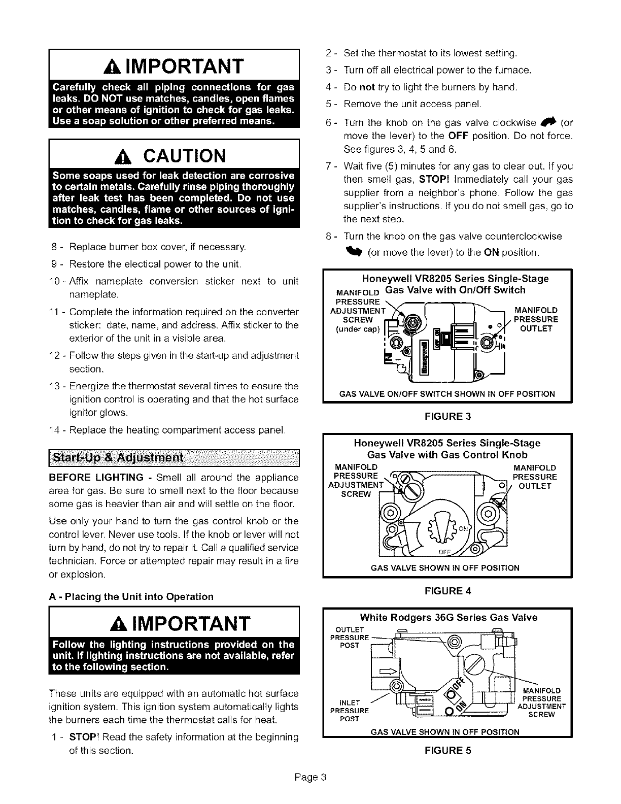
Remove burner box cover, if necessary. Turn the
automatic gas valve knob, or switch the gas valve
lever, to the OFF position (figures 3, 4, 5 and 6).
3 - Disconnect the gas supply from the gas valve. Mark
the wires for identification and disconnect the wiring
at the gas valve.
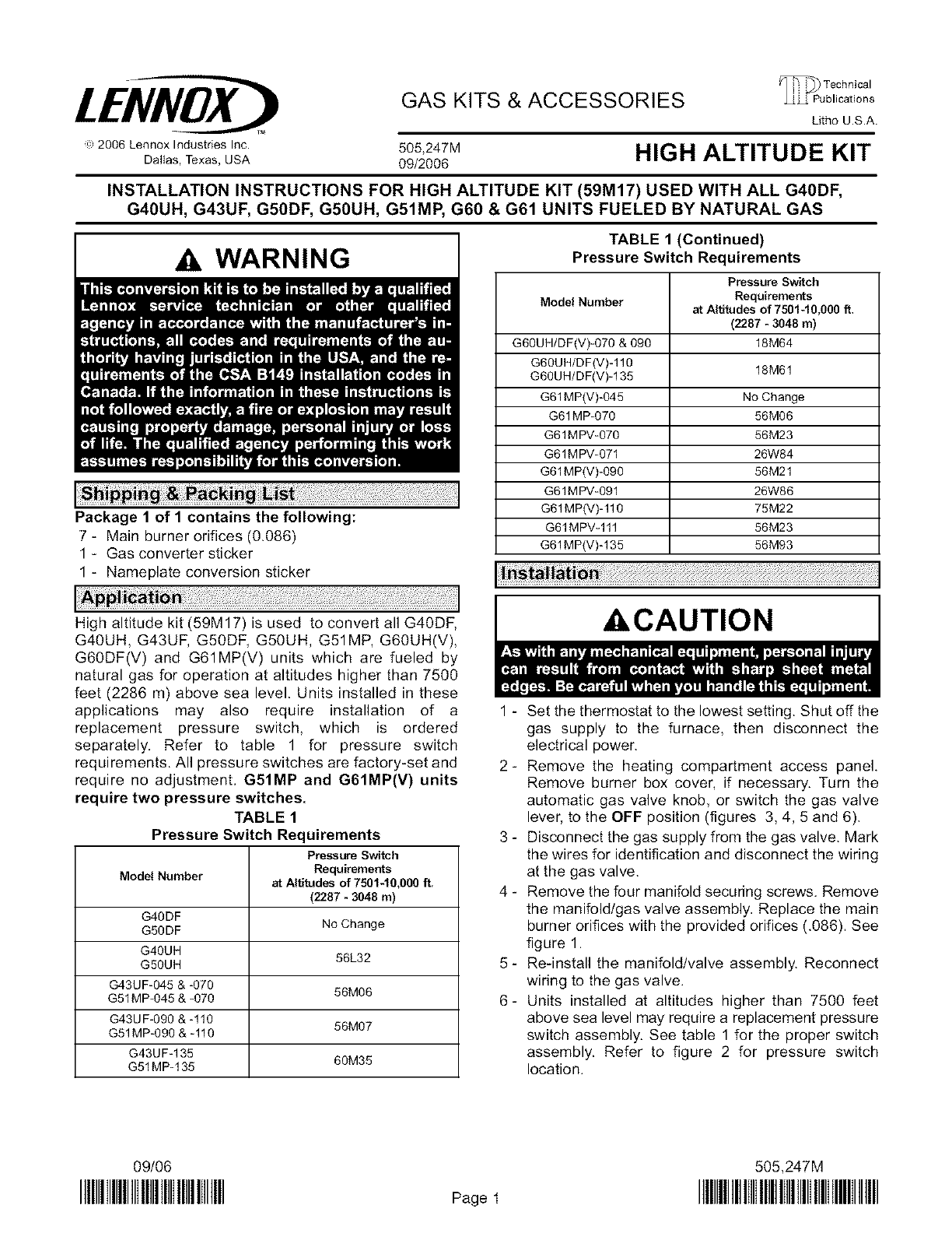
4 - Remove the four manifold securing screws, Remove
the manifold/gas valve assembly, Replace the main
burner orifices with the provided orifices (.086). See
figure 1.
5- Re-install the manifold/valve assembly. Reconnect
wiring to the gas valve.
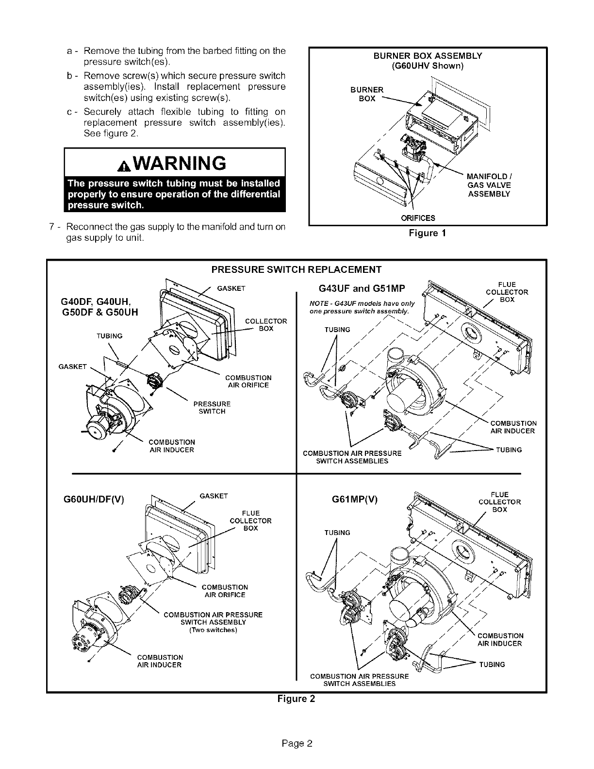
6- Units installed at altitudes higher than 7500 feet
above sea level may require a replacement pressure
switch assembly. See table 1 for the proper switch
assembly. Refer to figure 2 for pressure switch
location.
09/06 505,247M
IIIIIIIIIIIIIIIIIIIIIIIIIIIIIIIIIIIIIIII Page1 IIIIIIIIIIIIIIIIIIIIIIIIIIIIIIIIIIIIIIIIIIIIIIIIII
a - Remove the tubing from the barbed fitting on the
pressure switch(es).
b - Remove screw(s) which secure pressure switch
assembly(ies). Install replacement pressure
switch(es) using existing screw(s),
c- Securely attach flexible tubing to fitting on
replacement pressure switch assembly(ies).
See figure 2,
=,WARNING
7 - Reconnect the gas supply to the manifold and turn on
gas supply to unit,
BURNER BOX ASSEMBLY
(GGOUHV Shown)
BURNER
BOX
MANIFOLD t
GAS VALVE
ASSEMBLY
ORIFICES
Figure 1
G40DF, G40UH,
G50DF & G50UH
TUBING
GASKET
G60UH/DF(V)
PRESSURE SWITCH REPLACEMENT
GASKET G43UF and G51MP
COLLECTOR
BOX
COMBUSTION
AIR ORIFICE
PRESSURE
SWITCH
NOTE -G43UF models have only
one pressure switch assembly.
TUBING /
./
/ /
/
COMBUSTION
AIR INDUCER COMBUSTION AIRPRESSURE
SWITCH ASSEMBLIES
GASKET
FLUE
COLLECTOR
G61MP(V)
FLUE
COLLECTOR
BOX
BOX
COMBUSTION
AIR ORIFICE
COMBUSTION AIR PRESSURE
SWITCH ASSEMBLY
(Two switches)
COMBUSTION
AIR INDUCER
TUBING
/
COMBUSTION AIR PRESSURE
SWITCH ASSEMBLIES
/
./
7 _ COMBUSTION
/AIR INDUCER
/
/
FLUE
COLLECTOR
BOX
/AIRINDUCER
Figure 2
Page 2
IMPORTANT
A CAUTION
8 - Replace burner box cover, if necessary.
9 - Restore the electical power to the unit.
10-Affix nameplate conversion sticker next to unit
nameplate.
11 - Complete the information required on the converter
sticker: date, name, and address. Affix sticker to the
exterior of the unit in a visible area,
12 - Follow the steps given in the start-up and adjustment
section.
13 - Energize the thermostat several times to ensure the
ignition control is operating and that the hot surface
ignitor glows.
14 - Replace the heating compartment access panel.
BEFORE LIGHTING - Smell all around the appliance
area for gas. Be sure to smell next to the floor because
some gas is heavier than air and will settle on the floor.
Use only your hand to turn the gas control knob or the
control lever. Never use tools. If the knob or lever will not
turn by hand, do not try to repair it. Call a qualified service
technician. Force or attempted repair may result in a fire
or explosion.
A-Placing the Unit into Operation
IMPORTANT
These units are equipped with an automatic hot surface
ignition system. This ignition system automatically lights
the burners each time the thermostat calls for heat.
1 - STOP! Read the safety information at the beginning
of this section.
2 - Set the thermostat to its lowest setting,
3 - Turn off all electrical power to the furnace,
4- Do not try to light the burners by hand.
5 - Remove the unit access panel.
6 - Turn the knob on the gas valve clockwise _ (or
move the lever) to the OFF position. Do not force,
See figures 3, 4, 5 and 6.
7 - Wait five (5) minutes for any gas to clear out. If you
then smell gas, STOP! Immediately call your gas
supplier from a neighbor's phone, Follow the gas
supplier's instructions. If you do not smell gas, go to
the next step,
8 - Turn the knob on the gas valve counterclockwise
(or move the lever) to the ON position.
Honeywell VR8205 Series Single-Stage
MANIFOLDGas Valve with On/Off Switch
PRESSURE MANIFOLD
SCREW PRESSURE
(under cap) OUTLET
GAS VALVE ONtOFF SWITCH SHOWN IN OFF POSITION
FIGURE 3
Honeywell VR8205 Series Single-Stage
Gas Valve with Gas Control Knob
MANIFOLD
PRESSURE_
ADJUSTMENT
SCREW
MANIFOLD
GAS VALVE SHOWN IN OFF POSITION
FIGURE 4
White Rodgers 36G Series Gas Valve
OUTLET
PRESSURE_
POST
INLET J
PRESSURE
POST
MANIFOLD
PRESSURE
ADJUSTMENT
SCREW
GAS VALVE SHOWN tN OFF POSITION
FIGURE 5
Page 3
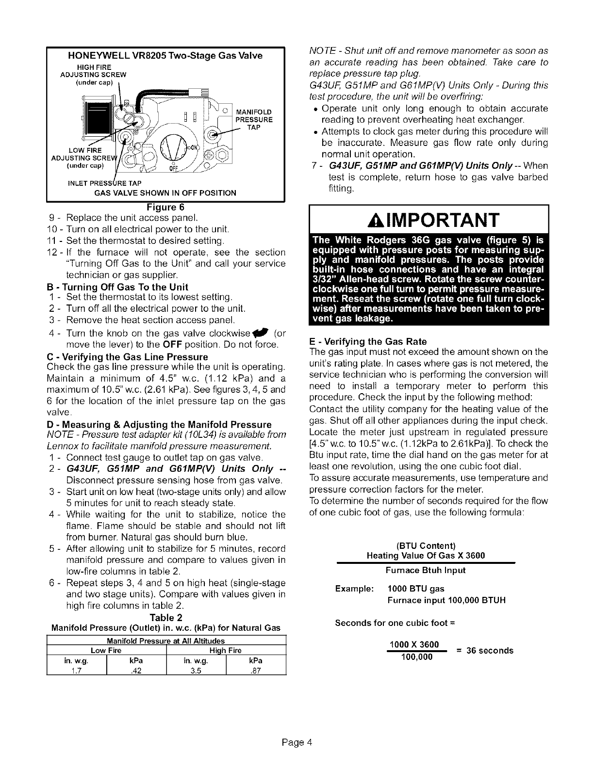
HONEYWELLVR8205Two-Stage Gas Valve
HIGH FIRE
ADJUSTING SCREW
(under cap)
MANIFOLD
PRESSURE
TAP
LOW FIRE
(under cap)
RE TAP
GAS VALVE SHOWN IN OFF POSITION
Figure 6
9 - Replace the unit access panel.
10 - Turn on all electrical power to the unit.
11 - Set the thermostat to desired setting.
12-If the furnace will not operate, see the section
"Turning Off Gas to the Unit" and call your service
technician or gas supplier.
B - Turning Off Gas To the Unit
1 - Set the thermostat to its lowest setting.
2 - Turn off all the electrical power to the unit.
3 - Remove the heat section access panel.
4 - Turn the knob on the gas valve clockwise1{_ (or
move the lever) to the OFF position. Do not force.
C - Verifying the Gas Line Pressure
Check the gas line pressure while the unit is operating.
Maintain a minimum of 4.5" w.c. (1.12 kPa) and a
maximum of 10.5" w.c. (2.61 kPa). See figures 3, 4, 5 and
6 for the location of the inlet pressure tap on the gas
valve.
D - Measuring & Adjusting the Manifold Pressure
NOTE -Pressure test adapter kit (10L34) is available from
Lennox to facilitate manifold pressure measurement.
1 - Connect test gauge to outlet tap on gas valve.
2- G43UF, G51MP and G61MP(V) Units Only --
Disconnect pressure sensing hose from gas valve.
3 - Start unit on low heat (two-stage units only) and allow
5 minutes for unit to reach steady state.
4- While waiting for the unit to stabilize, notice the
flame. Flame should be stable and should not lift
from burner. Natural gas should burn blue.
5 - After allowing unit to stabilize for 5 minutes, record
manifold pressure and compare to values given in
low-fire columns in table 2.
6 - Repeat steps 3, 4 and 5 on high heat (single-stage
and two stage units). Compare with values given in
high fire columns in table 2.
Table 2
Manifold Pressure (Outlet) in. w.c, (kPa) for Natural Gas
ManifoldPressure_AllAltitudes
Low Fire High Fire
in,w,g, lkPa in,w,g, 1 kPa
1.7 .42 3.5 .87
NOTE -Shut unit off and remove manometer as soon as
an accurate reading has been obtained. Take care to
replace pressure tap plug.
G43UF, G51MP and G61MP(V) Units Only- During this
test procedure, the unit will be overfiring:
• Operate unit only long enough to obtain accurate
reading to prevent overheating heat exchanger.
• Attempts to clock gas meter during this procedure will
be inaccurate. Measure gas flow rate only during
normal unit operation.
7- G43UF, G51MP and G61MP(V) Units Only -- When
test is complete, return hose to gas valve barbed
fitting.
XklMPORTANT
E - Verifying the Gas Rate
The gas input must not exceed the amount shown on the
unit's rating plate. In cases where gas is not metered, the
service technician who is performing the conversion will
need to install a temporary meter to perform this
procedure. Check the input by the following method:
Contact the utility company for the heating value of the
gas. Shut offall other appliances during the input check.
Locate the meter just upstream in regulated pressure
[4.5" w.c. to 10.5" w.c. (1.12kPa to 2.61kPa)]. To check the
Btu input rate, time the dial hand on the gas meter for at
least one revolution, using the one cubic foot dial.
To assure accurate measurements, use temperature and
pressure correction factors for the meter.
To determine the number of seconds required for the flow
of one cubic foot of gas, use the following formula:
(BTU Content)
Heating Value Of Gas X3600
Furnace Btuh Input
Example: 1000 BTU gas
Furnace input 160,000 BTUH
Seconds for one cubic foot =
1000 X 3600 = 36 seconds
100,000
Page 4
