LG Electronics USA 37LAD 37" LCD TV/ MONITOR User Manual User s Manual H
LG Electronics USA 37" LCD TV/ MONITOR User s Manual H
UserManual.wiki
>
LG Electronics USA
>
37LAD User Manual
USER MANUAL
Navigation menu
Upload a User Manual
Namespaces
Wiki Guide
HTML
PDF
Info
Views
User Manual
Discussion / Help
Navigation

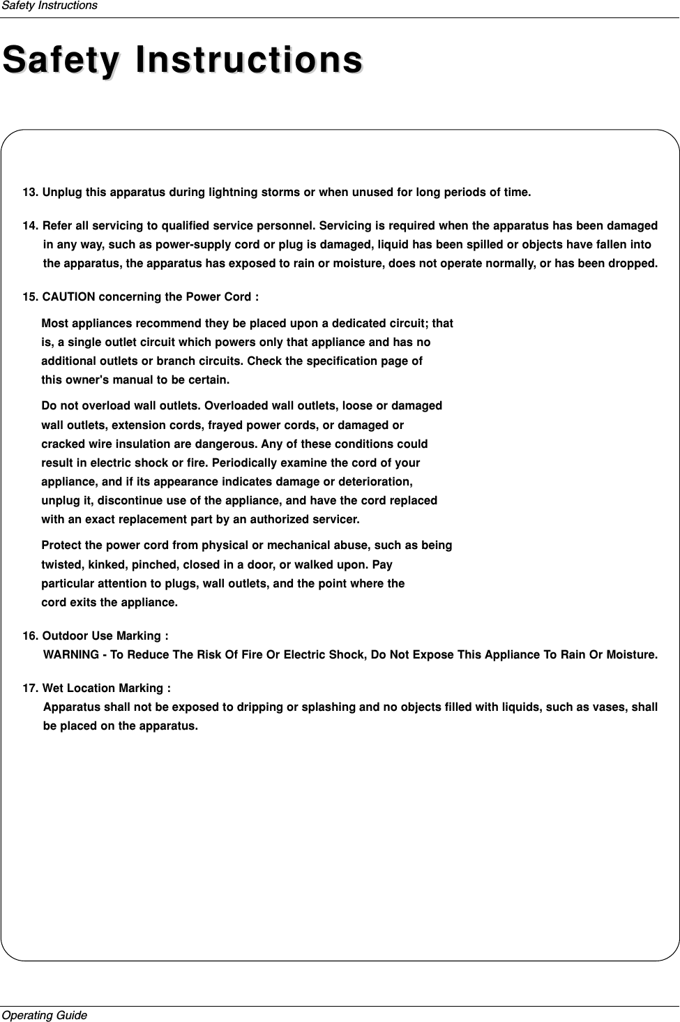
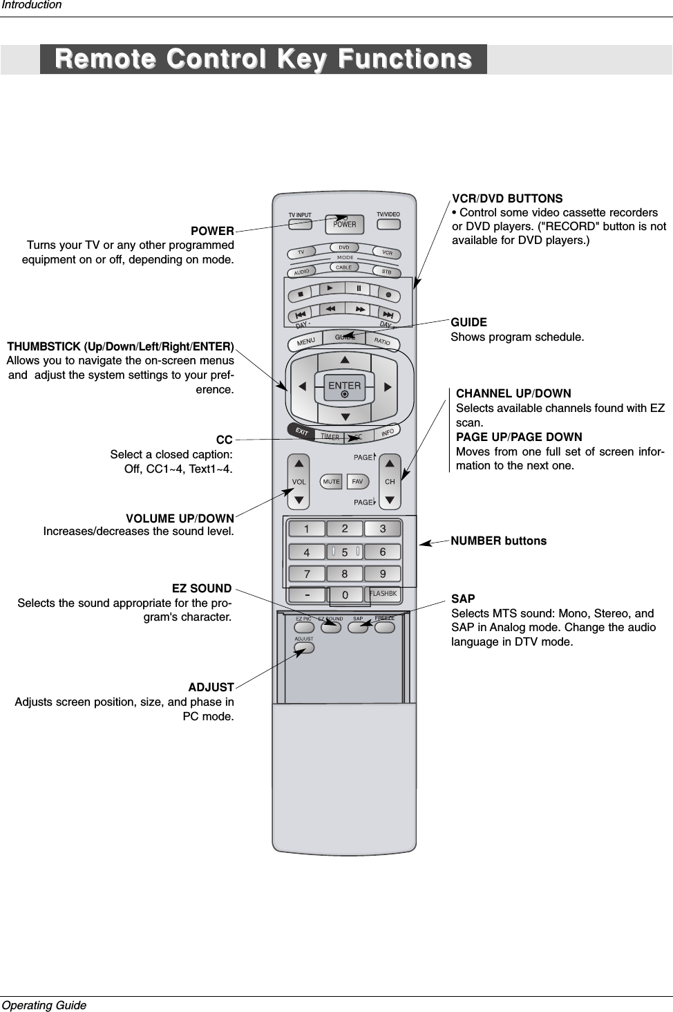
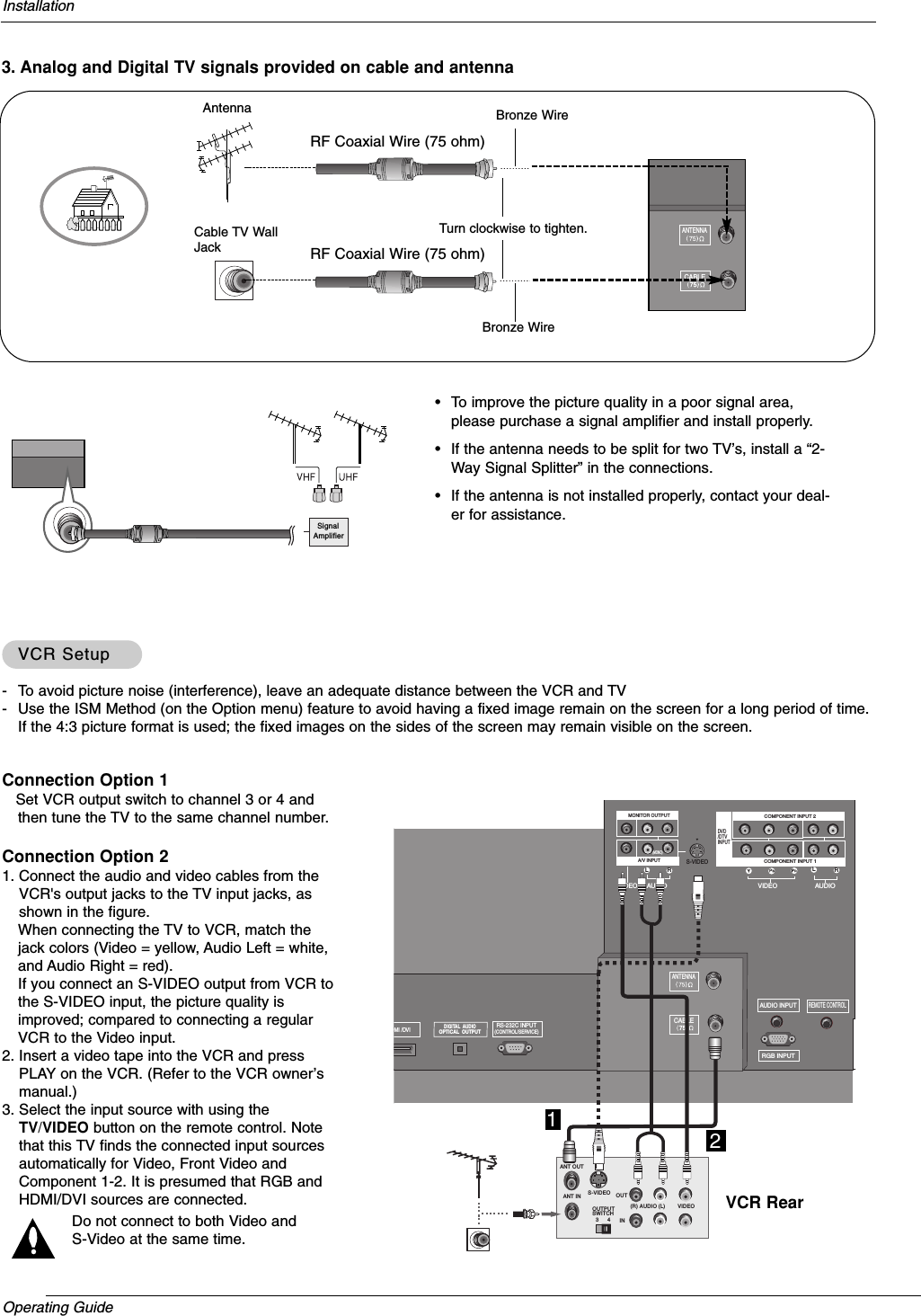
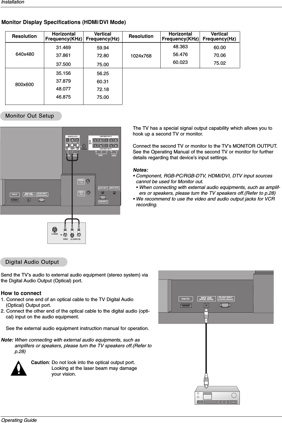
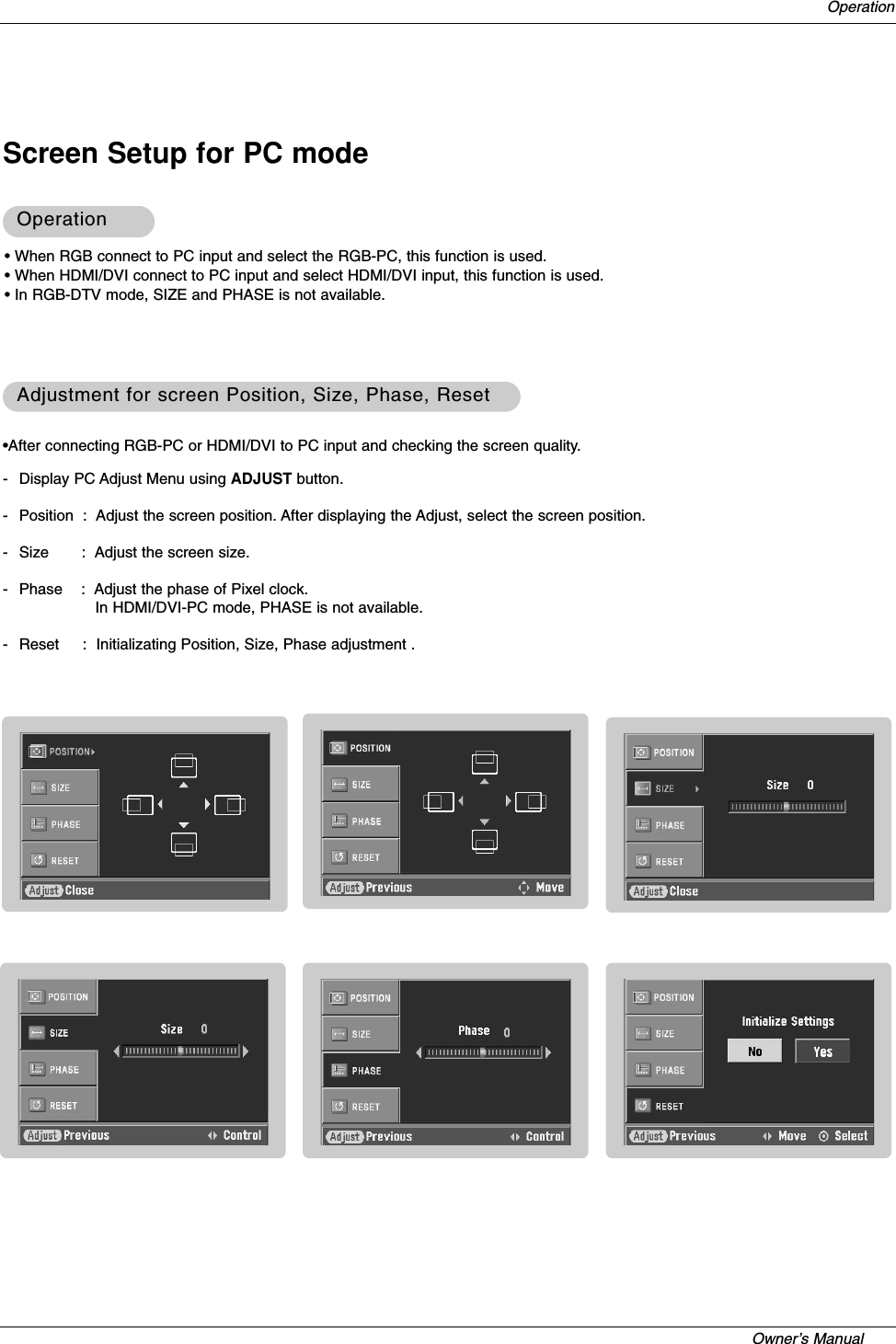
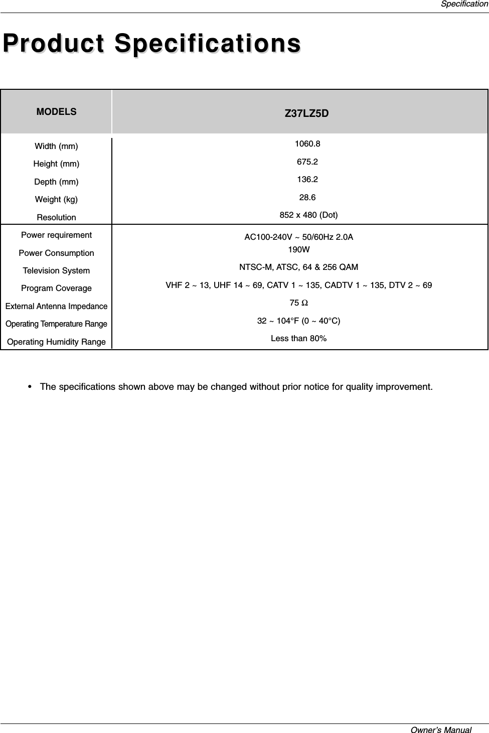
![Owner’s Manual External Control Device SetupSet IDSet IDUse this function to specify a monitor ID number. Refer to ‘Real Data Mapping’. See page 44.• Baud rate : 9600 bps (UART)• Data length : 8 bits• Parity : None* Use a crossed (reverse) cable.• Stop bit : 1 bit• Communication code : ASCII codeCommunication ParametersCommunication Parameters1. Press the MENU button and then use DD /EEbutton to select the SETUP menu.2. Press the GGbutton and then use DD /EEbutton to select SET ID.3. Press the GGbutton and then use DD /EEbutton to adjust SET ID to choose thedesired monitor ID number. The adjustment range of SET ID is 1 ~ 99.4. Press EXIT button to return to TV viewing or press MENU button to return to theprevious menu.Transmission* [Command 1]: First command to control the set.(j,k,m or x)* [Command 2]: Second command to control the set.* [Set ID]: You can adjust the set ID to choose desired monitorID number in Setup menu. Adjustment range is 1~ 99. When selecting Set ID ‘0’, every connectedthe TV is controlled. Set ID is indicated as decimal(1~99) on menu and as Hexa decimal (0x0~0x63)on transmission/receiving protocol.* [DATA]: To transmit command data.Transmit ‘FF’data to read status of command.* [Cr]: Carriage ReturnASCII code ‘0x0D’* [ ]: ASCII code ‘space (0x20)’[Command1][Command2][ ][Set ID][ ][Data][Cr]TTransmission / Receiving Protocolransmission / Receiving ProtocolOK Acknowledgement* The Monitor transmits ACK (acknowledgement) based onthis format when receiving normal data. At this time, if thedata is data read mode, it indicates present status data. Ifthe data is data write mode, it returns the data of the PCcomputer.[Command2][ ][Set ID][ ][OK][Data][x]Error Acknowledgement* The Monitor transmits ACK (acknowledgement) based onthis format when receiving abnormal data from non-viablefunctions or communication errors.[Command2][ ][Set ID][ ][NG][Data][x]Data 1: Illegal Code2: Not supported function3: Wait more time01. Power k a 0 ~ 102. Input Select k b 0 ~ 803. Aspect Ratio k c *04. Screen Mute k d 0 ~ 105. Volume Mute k e 0 ~ 106. Volume Control k f 0 ~ 6407. Contrast k g 0 ~ 6408. Brightness k h 0 ~ 6409. Color k i 0 ~ 6410. Tint k j 0 ~ 6411. Sharpness k k 0 ~ 6412. OSD Select k l 0 ~ 113. Remote Control Lock Mode k m 0 ~ 114. Treble k r 0 ~ 6415. Bass k s 0 ~ 6416. Balance k t 0 ~ 6417. Color Temperature k u 0 ~ 2COMMAND 1 COMMAND 2 DATA(Hexadecimal)Command Reference ListCommand Reference List18. Channel Tuning m a physical/program high major/program low major low minor high minor low attribute19. Channel Add/Del m b 00 ~ 0121. Input Select x b *COM-MAND 2COM-MAND 1DATA 0(Hexadecimal)DATA 1(Hexadecimal)DATA 2(Hexadecimal)DATA 3(Hexadecimal)DATA 4(Hexadecimal)DATA 5(Hexadecimal)SETUPVIDEOAUDIOTIMEOPTIONLOCK PreviousEZ ScanManual ScanChannel Edit GGDTV SignalChannel LabelInput SourceInput LabelSet ID GGMENU1](https://usermanual.wiki/LG-Electronics-USA/37LAD/User-Guide-554006-Page-23.png)
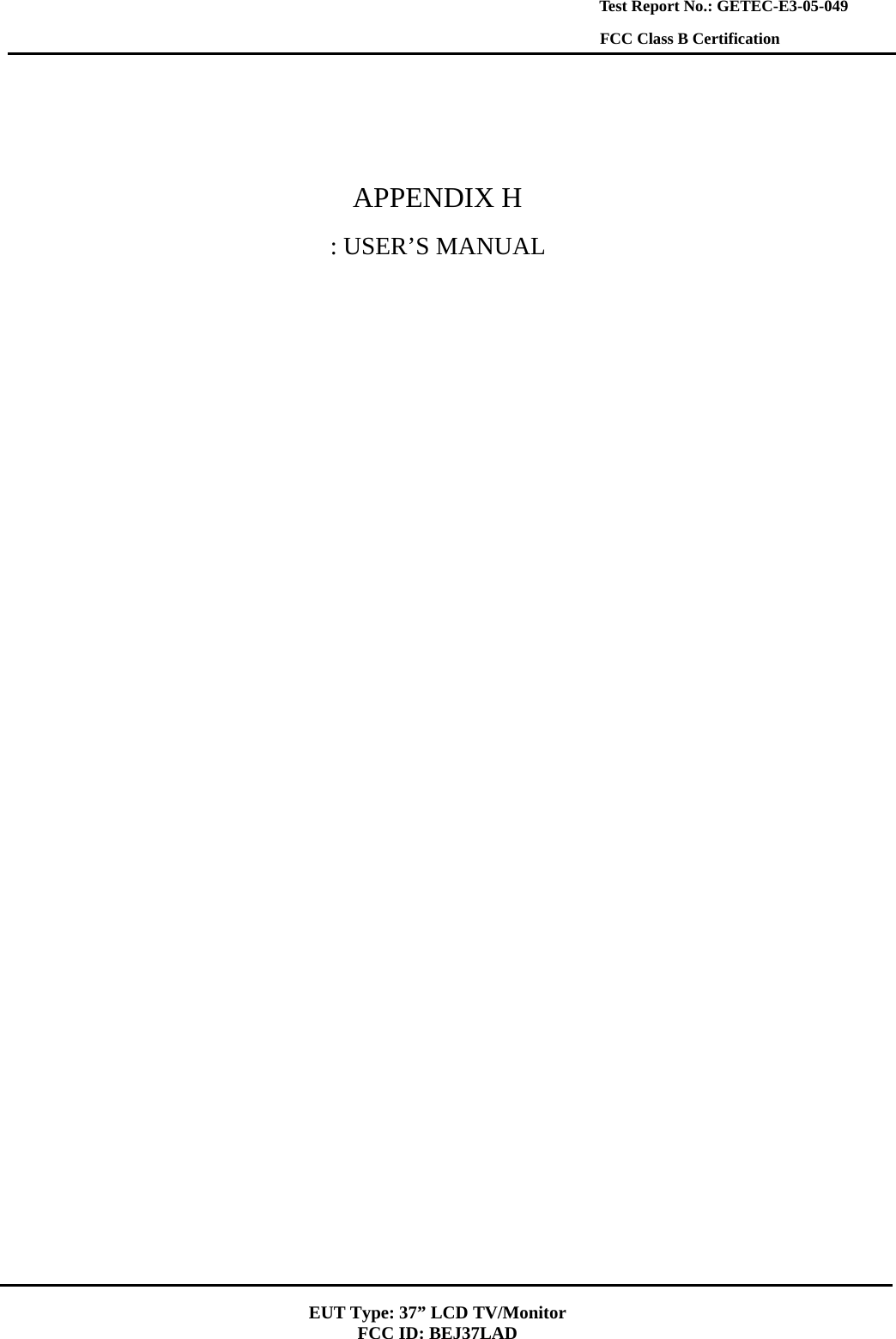
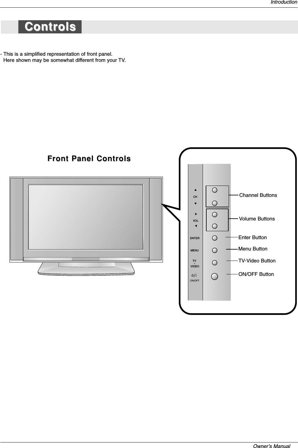
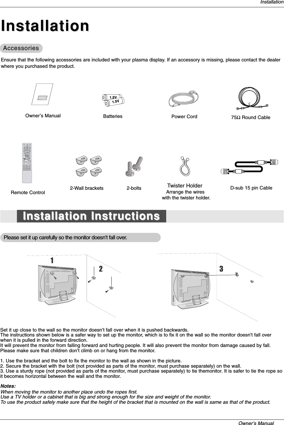
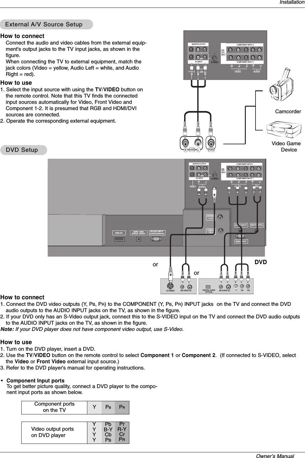
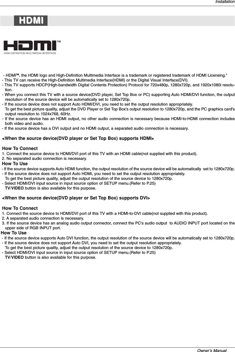
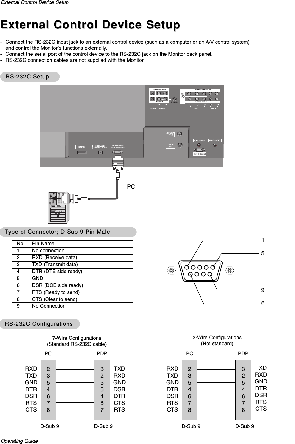
![Operating GuideExternal Control Device Setup02. Input Select (Command2:b) (Main Picture Input)GTo select input source for the Monitor.TransmissionData 0: DTV1: Analog2: Video3: Front Video4: Component 15: Component 26: RGB-DTV7: RGB-PC8: HDMI/DVIDate 1: 4:32: 16:93: Horizon4: Zoom 15: Zoom 26: Set by program10: Cinema Zoom (1)1F: Cinema Zoom (16)[k][b][ ][Set ID][ ][Data][Cr]Acknowledgement[b][ ][Set ID][ ][OK][Data][x]01. Power (Command2:a)GTo control Power On/Off of the Monitor.TransmissionData 0 : Power Off 1 : Power On[k][a][ ][Set ID][ ][Data][Cr]Acknowledgement[a][ ][Set ID][ ][OK][Data][x]* In a like manner, if other functions transmit ‘FF’databased on this format, Acknowledgement data feedbackpresents status about each function.* Real data mapping0 : Step 0A : Step 10 (SET ID 10)F : Step 15 (SET ID 15)10 : Step 16 (SET ID 16)63 : Step 99 (SET ID 99)64 : Step 10005. Volume Mute (Command2:e)GTo control volume mute on/off.You can also adjust mute using the MUTE button onremote control.TransmissionData 0 : Volume mute off (Volume on)1 : Volume mute on (Volume off)[k][e][ ][Set ID][ ][Data][Cr]Acknowledgement[e][ ][Set ID][ ][OK][Data][x]03. Aspect Ratio (Command2:c) (Main picture format)GTo adjust the screen format.You can also adjust the screen format using the RATIObutton on remote control or in the Option menu.Transmission[k][c][ ][Set ID][ ][Data][Cr]Acknowledgement[c][ ][Set ID][ ][OK][Data][x]04. Screen Mute (Command2:d)GTo select screen mute on/off.TransmissionData 0 : Screen mute off (Picture on)1 : Screen mute on (Picture off)[k][d][ ][Set ID][ ][Data][Cr]Acknowledgement[d][ ][Set ID][ ][OK][Data][x]06. Volume Control (Command2:f)GTo adjust volume.You can also adjust volume with the volume buttonson remote control.TransmissionData Min : 0 ~ Max : 64•Refer to ‘Real data mapping’as shown below.[k][f][ ][Set ID][ ][Data][Cr]Acknowledgement[f][ ][Set ID][ ][OK][Data][x]07. Contrast (Command2:g)GTo adjust screen contrast. You can also adjust contrast in the Video menu.TransmissionData Min : 0 ~ Max : 64•Refer to ‘Real data mapping’as shown below.[k][g][ ][Set ID][ ][Data][Cr]Acknowledgement[g][ ][Set ID][ ][OK][Data][x]08. Brightness (Command2:h)GTo adjust screen brightness.You can also adjust brightness in the Video menu.TransmissionData Min : 0 ~ Max : 64•Refer to ‘Real data mapping’as shown below.[k][h][ ][Set ID][ ][Data][Cr]Acknowledgement[h][ ][Set ID][ ][OK][Data][x]](https://usermanual.wiki/LG-Electronics-USA/37LAD/User-Guide-554006-Page-24.png)
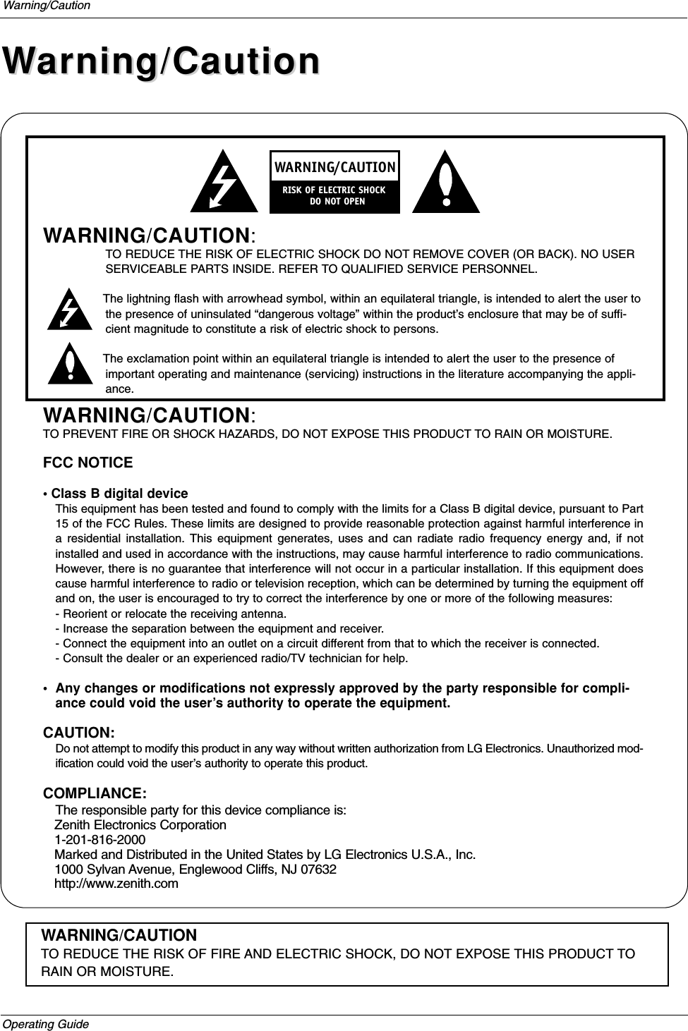
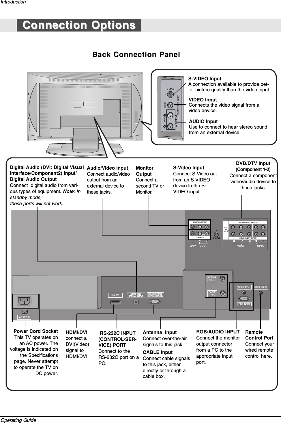
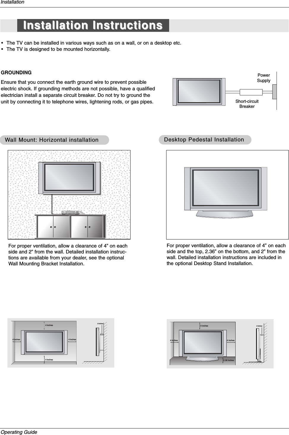
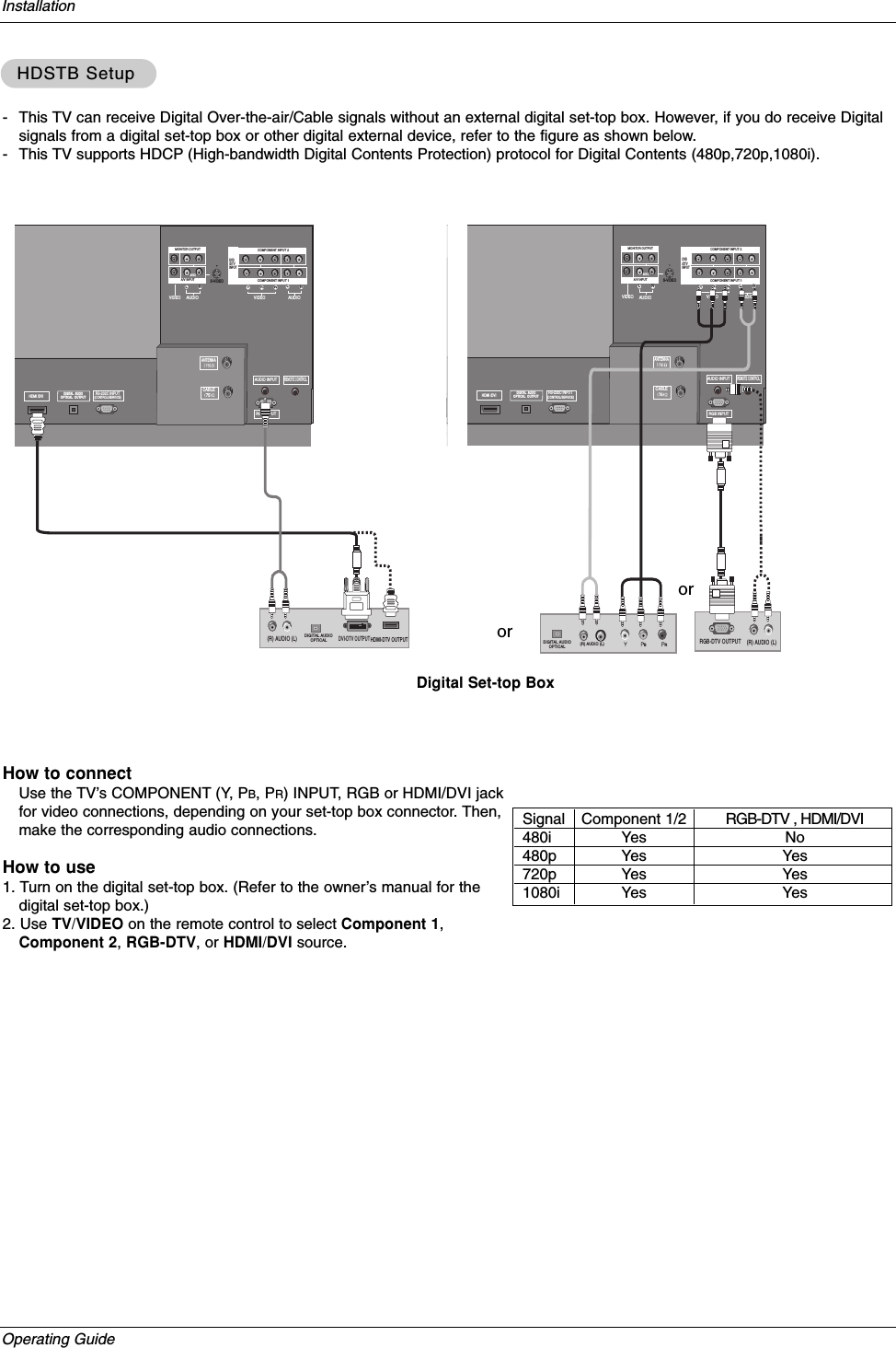
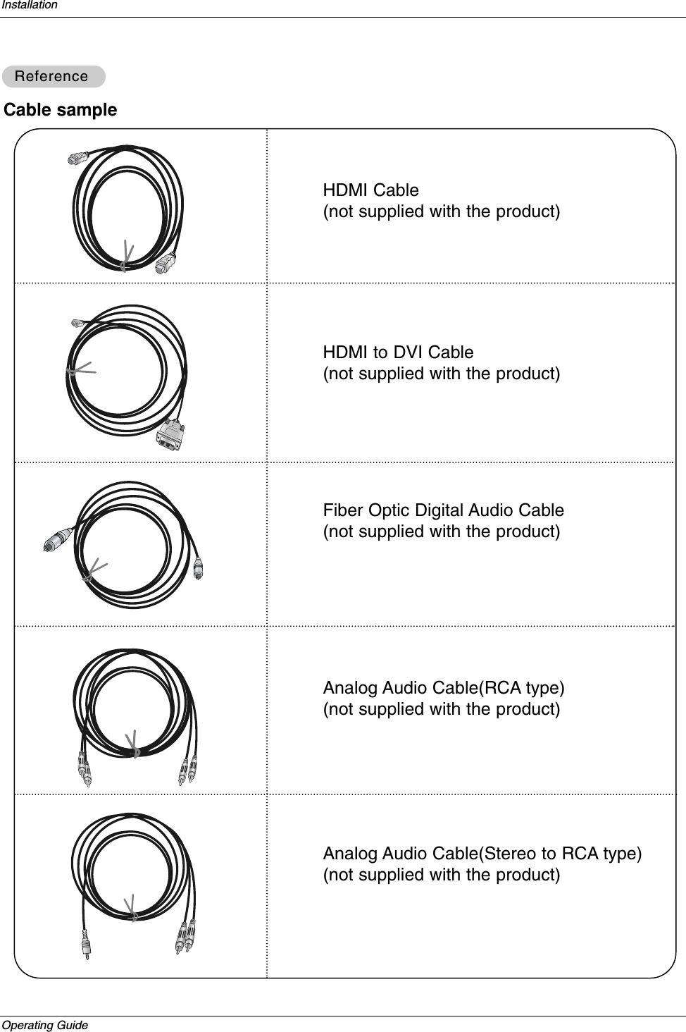
![Owner’s Manual External Control Device Setup09. Color (Command2:i)GTo adjust the screen color.You can also adjust color in the Video menu.TransmissionData Min : 0 ~ Max : 64•Refer to ‘Real data mapping’. See page 44.[k][i][ ][Set ID][ ][Data][Cr]Acknowledgement[i][ ][Set ID][ ][OK][Data][x]10. Tint (Command2:j)GTo adjust the screen tint.You can also adjust tint in the Video menu.TransmissionData Red : 0 ~ Green : 64•Refer to ‘Real data mapping’. See page 44.[k][j][ ][Set ID][ ][Data][Cr]Acknowledgement[ j ][ ][Set ID][ ][OK][Data][x]13. Remote Control Lock Mode (Command2:m)GTo lock the remote control and the front panel controls onthe set.Transmission[k][m][ ][Set ID][ ][Data][Cr]AcknowledgementData 0: Lock off 1: Lock on[m][ ][Set ID][ ][OK][Data][x]GTo adjust the screen sharpness.You can also adjust sharpness in the Video menu.Transmission11. Sharpness (Command2:k)Data Min: 0 ~ Max: 64•Refer to ‘Real data mapping’. See page 44.[k][k][ ][Set ID][ ][Data][Cr]Acknowledgement[k][ ][Set ID][ ][OK][Data][x]12. OSD Select (Command2:l)GTo select OSD (On Screen Display) on/off.Transmission[k][l][ ][Set ID][ ][Data][Cr]AcknowledgementData 0: OSD off 1: OSD on[l][ ][Set ID][ ][OK][Data][x]14. Treble (Command2:r)GTo adjust treble.You can also adjust treble in the Audio menu.TransmissionData Min: 0 ~ Max: 64•Refer to ‘Real data mapping’. See page 44.[k][r][ ][Set ID][ ][Data][Cr]Acknowledgement[r][ ][Set ID][ ][OK][Data][x]16. Balance (Command2:t)GTo adjust balance.You can also adjust balance in the Audio menu.TransmissionData Min: 0 ~ Max: 64•Refer to ‘Real data mapping’. See page 44.[k][t][ ][Set ID][ ][Data][Cr]Acknowledgement[t][ ][Set ID][ ][OK][Data][x]15. Bass (Command2:s)GTo adjust bass.You can also adjust bass in the Audio menu.TransmissionData Min: 0 ~ Max: 64•Refer to ‘Real data mapping’. See page 44.[k][s][ ][Set ID][ ][Data][Cr]Acknowledgement[s][ ][Set ID][ ][OK][Data][x]](https://usermanual.wiki/LG-Electronics-USA/37LAD/User-Guide-554006-Page-25.png)
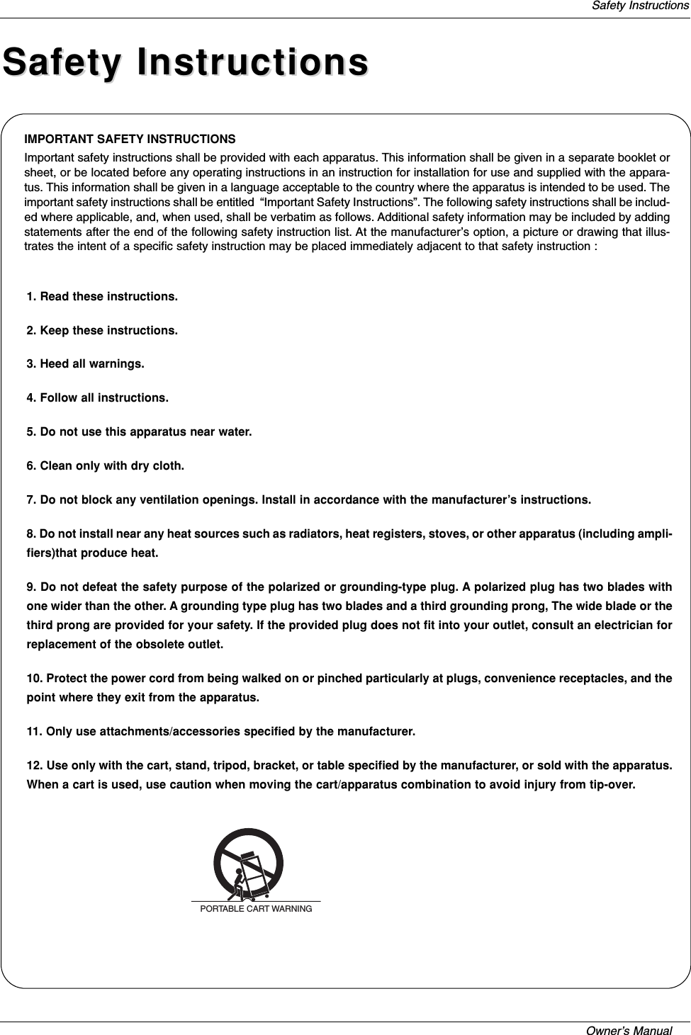
![Operating Guide[a][ ][Set ID][ ][OK][Data0][Data1][Data2][Data3][Data4][Data5][x][a][ ][Set ID][ ][NG][Data0][x]Acknowledgement* All data are transmitted by Hexadecimal code*Two/One part Channel: 6th bitThis bit is used in a cable-ready system.*Using physical channel: 5th bitIf the channel band is NTSC air or NTSC cable, channel tun-ing can be done by only physical channel. In this case, usingphysical channel bit must be low(0).But if the channel band is ATSC air or ATSC cable, there aretwo cases that physical channel enable or disable.If the physical channel sending is meaningful, you should setthis bit low(0). If the physical channel sending is meaningless,you should set this bit high(1).Example)1. Analog channel: NTSC cable, channel number(35), mainpicture Command: ma 00 23 xx xx xx xx 01 attribute(0x01):main picture, two part(it’s not mandatory), using physical chan-nel, NTSC cable ‘xx’data: don’t care major and minor channelnumber in case analog channel tuning. 2. Digital channel: ATSC air, channel number(don’t know phys-ical channel, major(30), minor(3)), main pictureCommand: ma 00 xx 00 1E 00 03 22 attribute(0x22): picture,two part, not using physical channel, ATSC air ‘xx’data: don’tcare analog channel number in case digital channel tuning.3. Digital channel: ATSC air, channelnumber(physical(20),major(30), minor(5)), main pictureCommand: ma 00 14 00 1E 00 05 02 attribute(0x02): main pic-ture, two part, using physical channel, ATSC air.19. Channel Add/Del (Command: m b)GTo add and delete the channelsTransmissionData 0: Channel Delete1: Channel Add[m][b][ ][Set ID][ ][Data][Cr][b][ ][Set ID][ ][OK][Data][x][b][ ][Set ID][ ][NG][Data][x]Acknowledgement20. Key (Command: m c)GTo send IR remote key codeTransmissionData Key code: Refer to page 49.[m][c][ ][Set ID][ ][Data][ ][Cr][c][ ][Set ID][ ][OK][Data][x]AcknowledgementExternal Control Device Setup17. Color Temperature (Command2:u)GTo adjust color temperature.You can also adjust color temperature in the Videomenu.TransmissionData 0: Medium 1: Cool 2: Warm[k][u][ ][Set ID][ ][Data][Cr]Acknowledgement[u][ ][Set ID][ ][OK][Data][x]18. Tune Command (Command: m a)GTo tune channel to following physical/major/minor numberTransmissionData 0: Physical Channel Number(Transmit by Hexadecimal code) NTSC air:02~45NTSC cable: 01, 0E~7DATSC air:01~45ATSC cable:01~87Data 1,Data 2: Major Channel Number (two part)/ Channel Number (One part) Data1: High byteData2: Low byteTwo part channel number: Major number-Minor numberOne part channel number: If the channel band is ATSC digital cable, it can be used. In case of using one part channel number, minor channel does not need. Data 3, Data 4: Minor Channel Number(Data 3: High byte)(Data 4: Low byte)Data 5:[m][a][ ][Set ID][ ][Data0][ ][Data1][ ][Data2][ ][Data3][ ][Data4][ ][Data5][Cr]7MainPicture 6Two/OnePartChannelUsingPhysicalChannel4Reserved 3210Step01Main 01TwoOneUseNo Usexxxxxxxxxxxx01000000011110000110010101110110xx0110NTSC AirATSCcable_autoATSCCable_ircATSCCable_hrcATSCCable_stdNTSC CableATSC AirReserved...Reserved501](https://usermanual.wiki/LG-Electronics-USA/37LAD/User-Guide-554006-Page-26.png)
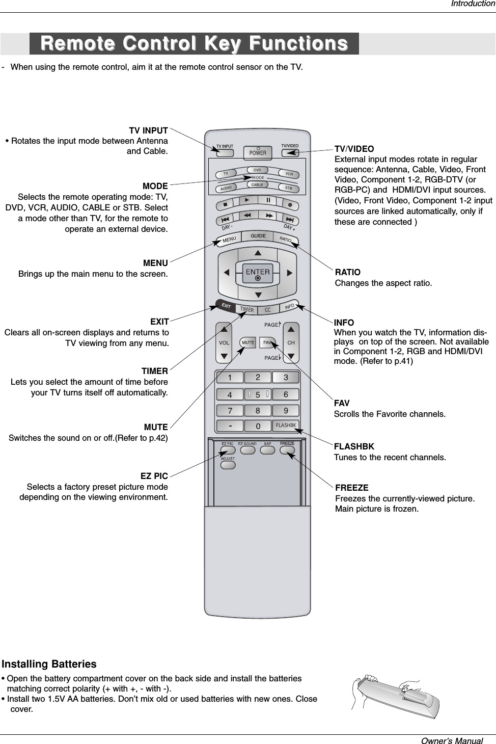
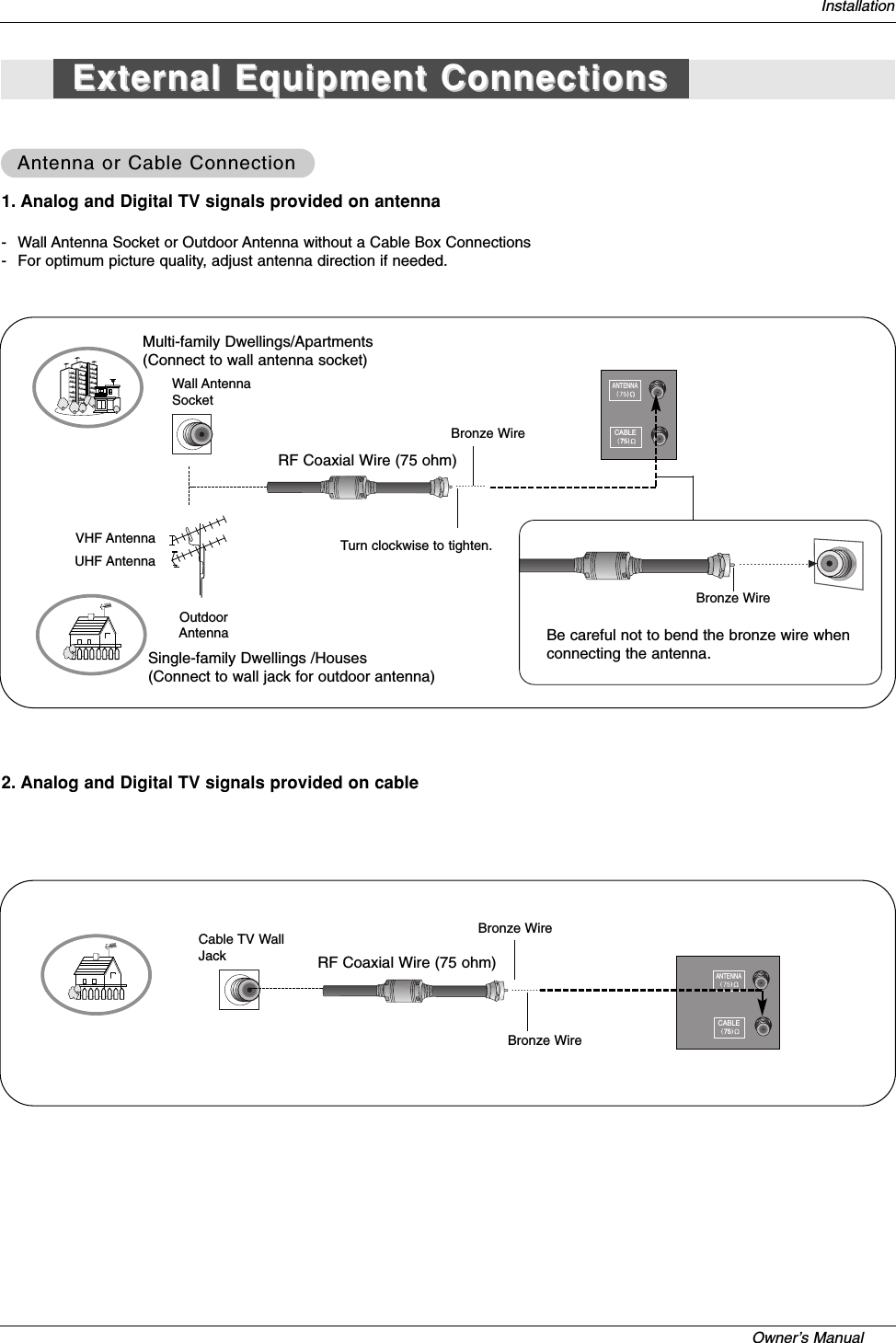
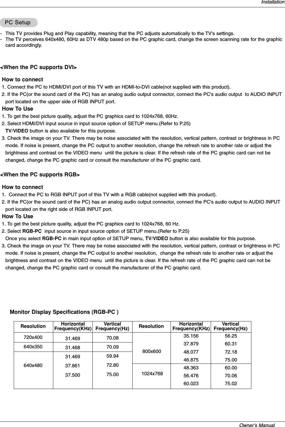
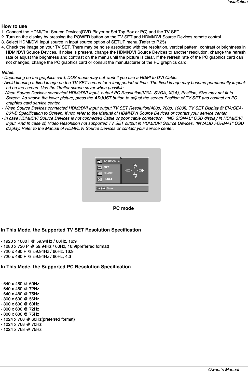
![Owner’s Manual External Control Device Setup21. Input select(Command: x b) (Main Picture Input)GTo select input source for TV. Transmission[x][b][][Set ID][][Data][Cr][b][ ][Set ID][ ][OK/NG][Data][x]AcknowledgementData StructureDATA(Hex) INPUT00 DTV (Antenna)01101120214041506090DTV (Cable)Analog (Antenna)Analog (Cable)VideoFront VideoComponent 1Component 2RGB DTVRGB PCHDMI/DVI](https://usermanual.wiki/LG-Electronics-USA/37LAD/User-Guide-554006-Page-27.png)