LG Electronics USA 37LAD 37" LCD TV/ MONITOR User Manual User s Manual H
LG Electronics USA 37" LCD TV/ MONITOR User s Manual H
USER MANUAL

EUT Type: 37” LCD TV/Monitor
FCC ID: BEJ37LAD
Test Report No.: GETEC-E3-05-049
FCC Class B Certification
APPENDIX H
: USER’S MANUAL

© Copyright 2005, LG Electronics USA, Inc.
Installation and Operating Guide | Warranty
Model Numbers |Z37LZ5D |LCD TV
Operating Guide
Warning/Caution
WARNING/CAUTION:
TO REDUCE THE RISK OF ELECTRIC SHOCK DO NOT REMOVE COVER (OR BACK). NO USER
SERVICEABLE PARTS INSIDE. REFER TO QUALIFIED SERVICE PERSONNEL.
The lightning flash with arrowhead symbol, within an equilateral triangle, is intended to alert the user to
the presence of uninsulated “dangerous voltage” within the product’s enclosure that may be of suffi-
cient magnitude to constitute a risk of electric shock to persons.
The exclamation point within an equilateral triangle is intended to alert the user to the presence of
important operating and maintenance (servicing) instructions in the literature accompanying the appli-
ance.
WARNING/CAUTION:
TO PREVENT FIRE OR SHOCK HAZARDS, DO NOT EXPOSE THIS PRODUCT TO RAIN OR MOISTURE.
FCC NOTICE
• Class B digital device
This equipment has been tested and found to comply with the limits for a Class B digital device, pursuant to Part
15 of the FCC Rules. These limits are designed to provide reasonable protection against harmful interference in
a residential installation. This equipment generates, uses and can radiate radio frequency energy and, if not
installed and used in accordance with the instructions, may cause harmful interference to radio communications.
However, there is no guarantee that interference will not occur in a particular installation. If this equipment does
cause harmful interference to radio or television reception, which can be determined by turning the equipment off
and on, the user is encouraged to try to correct the interference by one or more of the following measures:
- Reorient or relocate the receiving antenna.
- Increase the separation between the equipment and receiver.
- Connect the equipment into an outlet on a circuit different from that to which the receiver is connected.
- Consult the dealer or an experienced radio/TV technician for help.
• Any changes or modifications not expressly approved by the party responsible for compli-
ance could void the user’s authority to operate the equipment.
CAUTION:
Do not attempt to modify this product in any way without written authorization from LG Electronics. Unauthorized mod-
ification could void the user’s authority to operate this product.
COMPLIANCE:
The responsible party for this device compliance is:
Zenith Electronics Corporation
1-201-816-2000
Marked and Distributed in the United States by LG Electronics U.S.A., Inc.
1000 Sylvan Avenue, Englewood Cliffs, NJ 07632
http://www.zenith.com
WARNING
RISK OF ELECTRIC SHOCK
DO NOT OPEN
/CAUTION
WARNING/CAUTION
TO REDUCE THE RISK OF FIRE AND ELECTRIC SHOCK, DO NOT EXPOSE THIS PRODUCT TO
RAIN OR MOISTURE.
W
Warning/Caution
arning/Caution
Owner’s Manual
Safety Instructions
IMPORTANT SAFETY INSTRUCTIONS
Important safety instructions shall be provided with each apparatus. This information shall be given in a separate booklet or
sheet, or be located before any operating instructions in an instruction for installation for use and supplied with the appara-
tus. This information shall be given in a language acceptable to the country where the apparatus is intended to be used. The
important safety instructions shall be entitled “Important Safety Instructions”. The following safety instructions shall be includ-
ed where applicable, and, when used, shall be verbatim as follows. Additional safety information may be included by adding
statements after the end of the following safety instruction list. At the manufacturer’s option, a picture or drawing that illus-
trates the intent of a specific safety instruction may be placed immediately adjacent to that safety instruction :
1. Read these instructions.
2. Keep these instructions.
3. Heed all warnings.
4. Follow all instructions.
5. Do not use this apparatus near water.
6. Clean only with dry cloth.
7. Do not block any ventilation openings. Install in accordance with the manufacturer’s instructions.
8. Do not install near any heat sources such as radiators, heat registers, stoves, or other apparatus (including ampli-
fiers)that produce heat.
9. Do not defeat the safety purpose of the polarized or grounding-type plug. A polarized plug has two blades with
one wider than the other. A grounding type plug has two blades and a third grounding prong, The wide blade or the
third prong are provided for your safety. If the provided plug does not fit into your outlet, consult an electrician for
replacement of the obsolete outlet.
10. Protect the power cord from being walked on or pinched particularly at plugs, convenience receptacles, and the
point where they exit from the apparatus.
11. Only use attachments/accessories specified by the manufacturer.
12. Use only with the cart, stand, tripod, bracket, or table specified by the manufacturer, or sold with the apparatus.
When a cart is used, use caution when moving the cart/apparatus combination to avoid injury from tip-over.
Safety Instructions
Safety Instructions
PORTABLE CART WARNING

Operating Guide
Safety Instructions
13. Unplug this apparatus during lightning storms or when unused for long periods of time.
14. Refer all servicing to qualified service personnel. Servicing is required when the apparatus has been damaged
in any way, such as power-supply cord or plug is damaged, liquid has been spilled or objects have fallen into
the apparatus, the apparatus has exposed to rain or moisture, does not operate normally, or has been dropped.
15. CAUTION concerning the Power Cord :
Most appliances recommend they be placed upon a dedicated circuit; that
is, a single outlet circuit which powers only that appliance and has no
additional outlets or branch circuits. Check the specification page of
this owner's manual to be certain.
Do not overload wall outlets. Overloaded wall outlets, loose or damaged
wall outlets, extension cords, frayed power cords, or damaged or
cracked wire insulation are dangerous. Any of these conditions could
result in electric shock or fire. Periodically examine the cord of your
appliance, and if its appearance indicates damage or deterioration,
unplug it, discontinue use of the appliance, and have the cord replaced
with an exact replacement part by an authorized servicer.
Protect the power cord from physical or mechanical abuse, such as being
twisted, kinked, pinched, closed in a door, or walked upon. Pay
particular attention to plugs, wall outlets, and the point where the
cord exits the appliance.
16. Outdoor Use Marking :
WARNING - To Reduce The Risk Of Fire Or Electric Shock, Do Not Expose This Appliance To Rain Or Moisture.
17. Wet Location Marking :
Apparatus shall not be exposed to dripping or splashing and no objects filled with liquids, such as vases, shall
be placed on the apparatus.
Safety Instructions
Safety Instructions
Owner’s Manual
Introduction
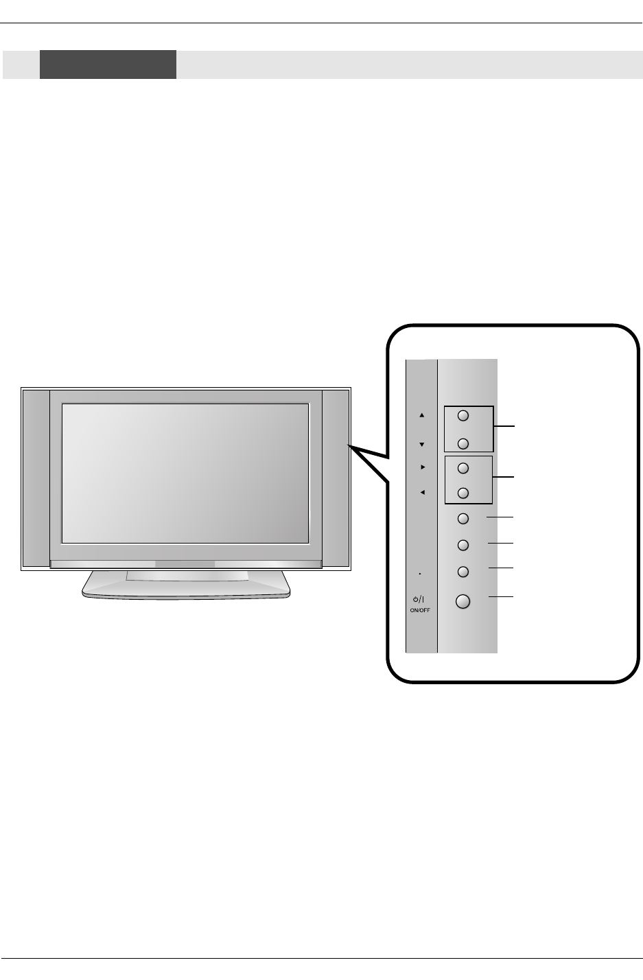
- This is a simplified representation of front panel.
Here shown may be somewhat different from your TV.
Controls
Controls
CH
VOL
ENTER
MENU
TV
VIDEO
Channel Buttons
Volume Buttons
Enter Button
Menu Button
TV·Video Button
ON/OFF Button
Front Panel Controls
Front Panel Controls
Operating Guide
Introduction
AUDIO
R
L
VIDEO
COMPONENT INPUT 1
R
L
(MONO)
COMPONENT INPUT 2
MONITOR OUTPUT
A/V INPUT
VIDEO
AUDIO
S-VIDEO
DVD
/DTV
INPUT
AUDIO INPUT
REMOTE CONTROL
RGB INPUT
ANTENNA
CABLE
AC INPUT
HDMI /DVI
DIGITAL AUDIO
OPTICAL OUTPUT
(CONTROL/SERVICE)
RS-232C INPUT
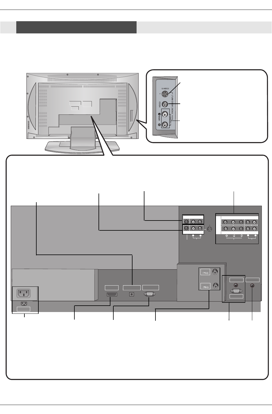
S-VIDEO Input
A connection available to provide bet-
ter picture quality than the video input.
VIDEO Input
Connects the video signal from a
video device.
AUDIO Input
Use to connect to hear stereo sound
from an external device.
Antenna Input
Connect over-the-air
signals to this jack.
CABLE Input
Connect cable signals
to this jack, either
directly or through a
cable box.
RGB/AUDIO INPUT
Connect the monitor
output connector
from a PC to the
appropriate input
port.
Digital Audio (DVI: Digital Visual
Interface/Component2) Input/
Digital Audio Output
Connect digital audio from vari-
ous types of equipment. Note: In
standby mode,
these ports will not work.
DVD/DTV Input
(Component 1-2)
Connect a component
video/audio device to
these jacks.
Remote
Control Port
Connect your
wired remote
control here.
S-Video Input
Connect S-Video out
from an S-VIDEO
device to the S-
VIDEO input.
RS-232C INPUT
(CONTROL/SER-
VICE) PORT
Connect to the
RS-232C port on a
PC.
HDMI/DVI
connect a
DVI(Video)
signal to
HDMI/DVI.
Audio/Video Input
Connect audio/video
output from an
external device to
these jacks.
Connection Options
Connection Options
Back Connection Panel
Back Connection Panel
Power Cord Socket
This TV operates on
an AC power. The
voltage is indicated on
the Specifications
page. Never attempt
to operate the TV on
DC power.
Monitor
Output
Connect a
second TV or
Monitor.
Owner’s Manual
Introduction
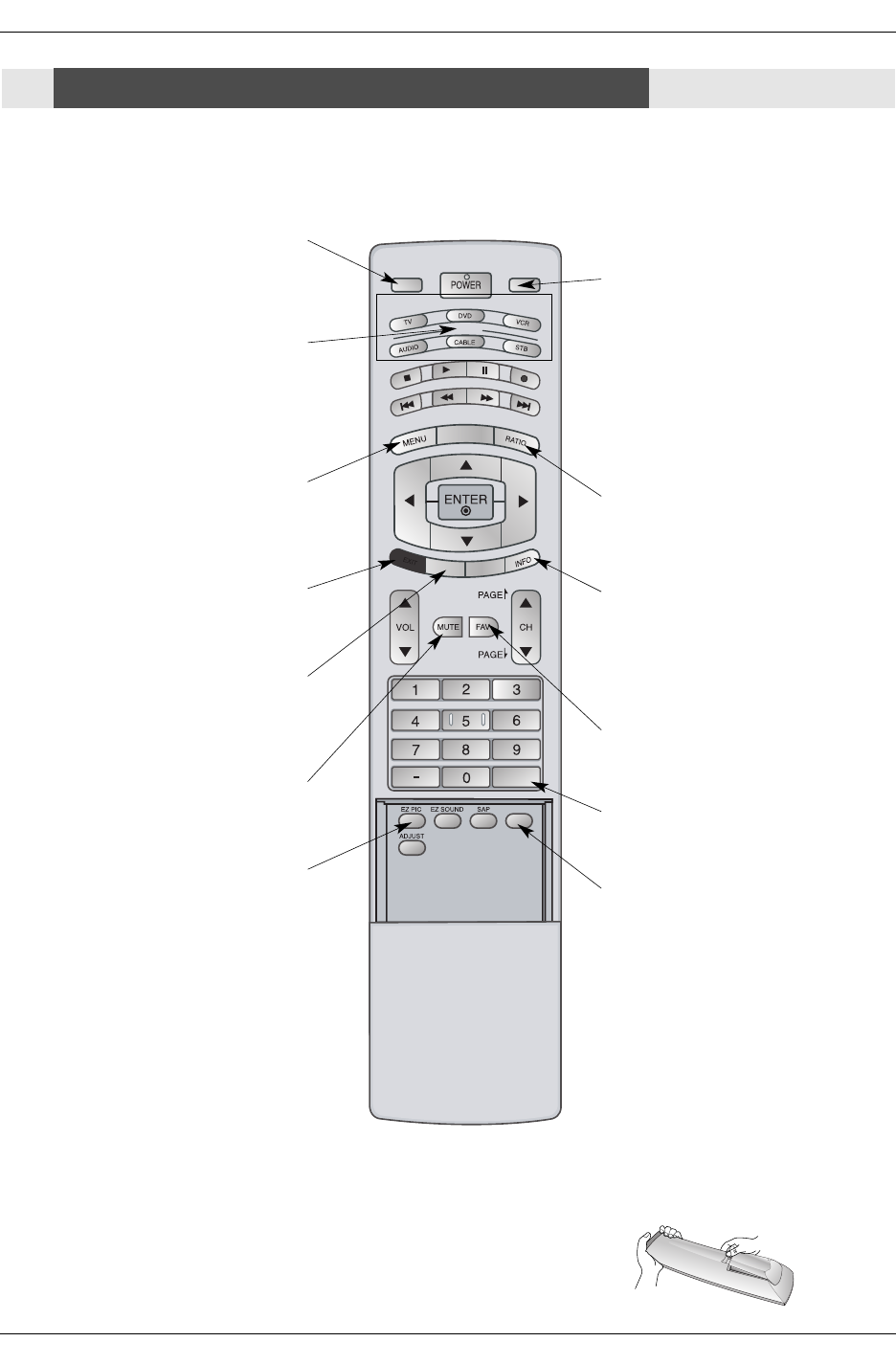
- When using the remote control, aim it at the remote control sensor on the TV.
MODE
DAY -
DAY +
FLASHBK
TIMER
FREEZE
TV INPUT TV/VIDEO
EXIT
GUIDE
CC
TV INPUT
• Rotates the input mode between Antenna
and Cable.
MUTE
Switches the sound on or off.
(Refer to p.42)
MODE
Selects the remote operating mode: TV,
DVD, VCR, AUDIO, CABLE or STB. Select
a mode other than TV, for the remote to
operate an external device.
FLASHBK
Tunes to the recent channels.
EXIT
Clears all on-screen displays and returns to
TV viewing from any menu.
TIMER
Lets you select the amount of time before
your TV turns itself off automatically.
MENU
Brings up the main menu to the screen.
EZ PIC
Selects a factory preset picture mode
depending on the viewing environment.
FREEZE
Freezes the currently-viewed picture.
Main picture is frozen.
TV/VIDEO
External input modes rotate in regular
sequence: Antenna, Cable, Video, Front
Video, Component 1-2, RGB-DTV (or
RGB-PC) and HDMI/DVI input sources.
(Video, Front Video, Component 1-2 input
sources are linked automatically, only if
these are connected )
RATIO
Changes the aspect ratio.
INFO
When you watch the TV, information dis-
plays on top of the screen. Not available
in Component 1-2, RGB and HDMI/DVI
mode. (Refer to p.41)
FAV
Scrolls the Favorite channels.
Installing Batteries
• Open the battery compartment cover on the back side and install the batteries
matching correct polarity (+ with +, - with -).
• Install two 1.5V AA batteries. Don’t mix old or used batteries with new ones. Close
cover.
Remote Control Key Functions
Remote Control Key Functions
Operating Guide
Introduction
MODE
DAY -
DAY +
FLASHBK
TIMER
FREEZE
TV INPUT TV/VIDEO
EXIT
GUIDE
CC
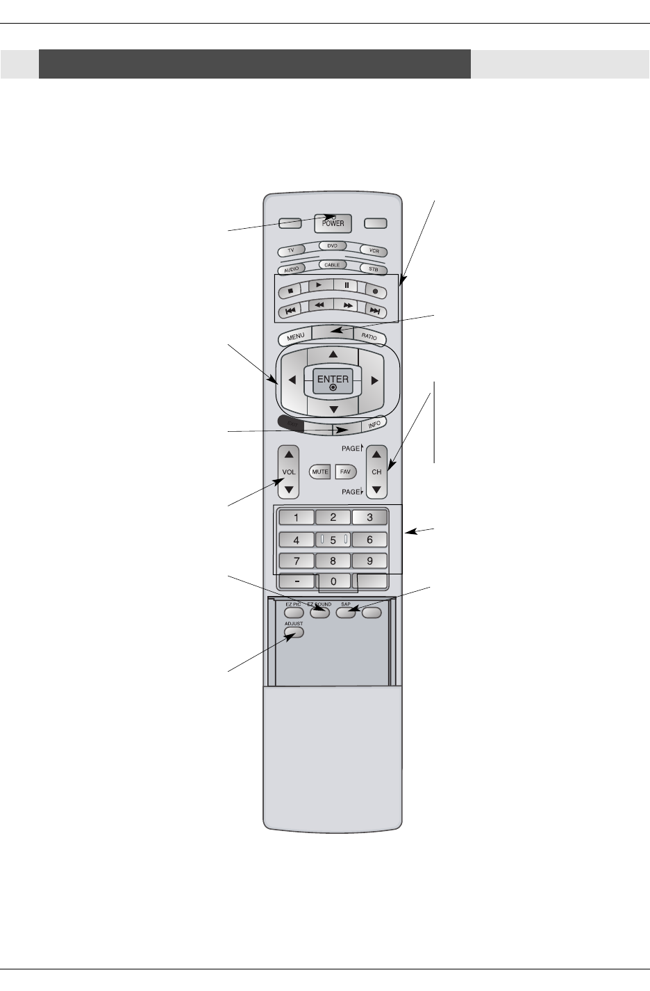
NUMBER buttons
VCR/DVD BUTTONS
• Control some video cassette recorders
or DVD players. ("RECORD" button is not
available for DVD players.)
POWER
Turns your TV or any other programmed
equipment on or off, depending on mode.
CC
Select a closed caption:
Off, CC1~4, Text1~4.
THUMBSTICK (Up/Down/Left/Right/ENTER)
Allows you to navigate the on-screen menus
and adjust the system settings to your pref-
erence. CHANNEL UP/DOWN
Selects available channels found with EZ
scan.
PAGE UP/PAGE DOWN
Moves from one full set of screen infor-
mation to the next one.
EZ SOUND
Selects the sound appropriate for the pro-
gram's character.
SAP
Selects MTS sound: Mono, Stereo, and
SAP in Analog mode. Change the audio
language in DTV mode.
VOLUME UP/DOWN
Increases/decreases the sound level.
GUIDE
Shows program schedule.
ADJUST
Adjusts screen position, size, and phase in
PC mode.
Remote Control Key Functions
Remote Control Key Functions
Owner’s Manual
Installation
Owner’s Manual
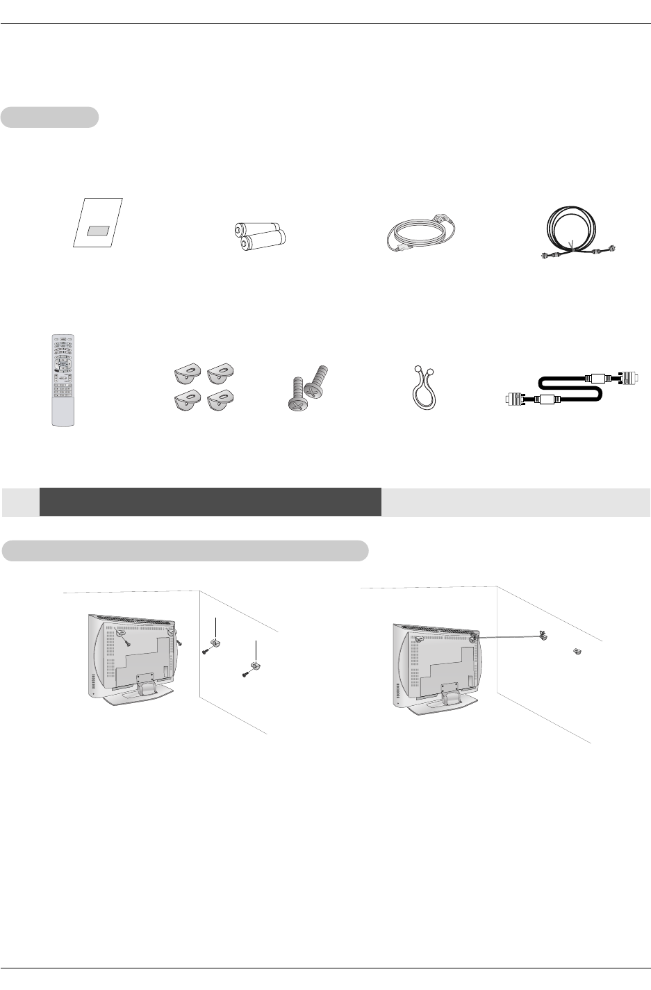
1.5V
1.5V
Batteries Power Cord
MODE
DAY -
DAY +
FLASHBK
TIMER
TV INPUT TV/VIDEO
EXIT
GUIDE
CC
75ΩRound Cable
Ensure that the following accessories are included with your plasma display. If an accessory is missing, please contact the dealer
where you purchased the product.
2-Wall brackets 2-bolts
Remote Control
Please set it up carefully so the monitor doesn’t fall over.
Set it up close to the wall so the monitor doesn’t fall over when it is pushed backwards.
The instructions shown below is a safer way to set up the monitor, which is to fix it on the wall so the monitor doesn’t fall over
when it is pulled in the forward direction.
It will prevent the monitor from falling forward and hurting people. It will also prevent the monitor from damage caused by fall.
Please make sure that children don’t climb on or hang from the monitor.
1. Use the bracket and the bolt to fix the monitor to the wall as shown in the picture.
2. Secure the bracket with the bolt (not provided as parts of the monitor, must purchase separately) on the wall.
3. Use a sturdy rope (not provided as parts of the monitor, must purchase separately) to tie themonitor. It is safer to tie the rope so
it becomes horizontal between the wall and the monitor.
Notes:
When moving the monitor to another place undo the ropes first.
Use a TV holder or a cabinet that is big and strong enough for the size and weight of the monitor.
To use the product safely make sure that the height of the bracket that is mounted on the wall is same as that of the product.
Installation
Installation
Installation Instructions
Installation Instructions
Accessories
Accessories
D-sub 15 pin Cable
Twister Holder
Arrange the wires
with the twister holder.
1
23
Operating Guide
Installation
GROUNDING
Ensure that you connect the earth ground wire to prevent possible
electric shock. If grounding methods are not possible, have a qualified
electrician install a separate circuit breaker. Do not try to ground the
unit by connecting it to telephone wires, lightening rods, or gas pipes.
Power
Supply
Short-circuit
Breaker
4 inches
4 inches
4 inches4 inches
2 inches
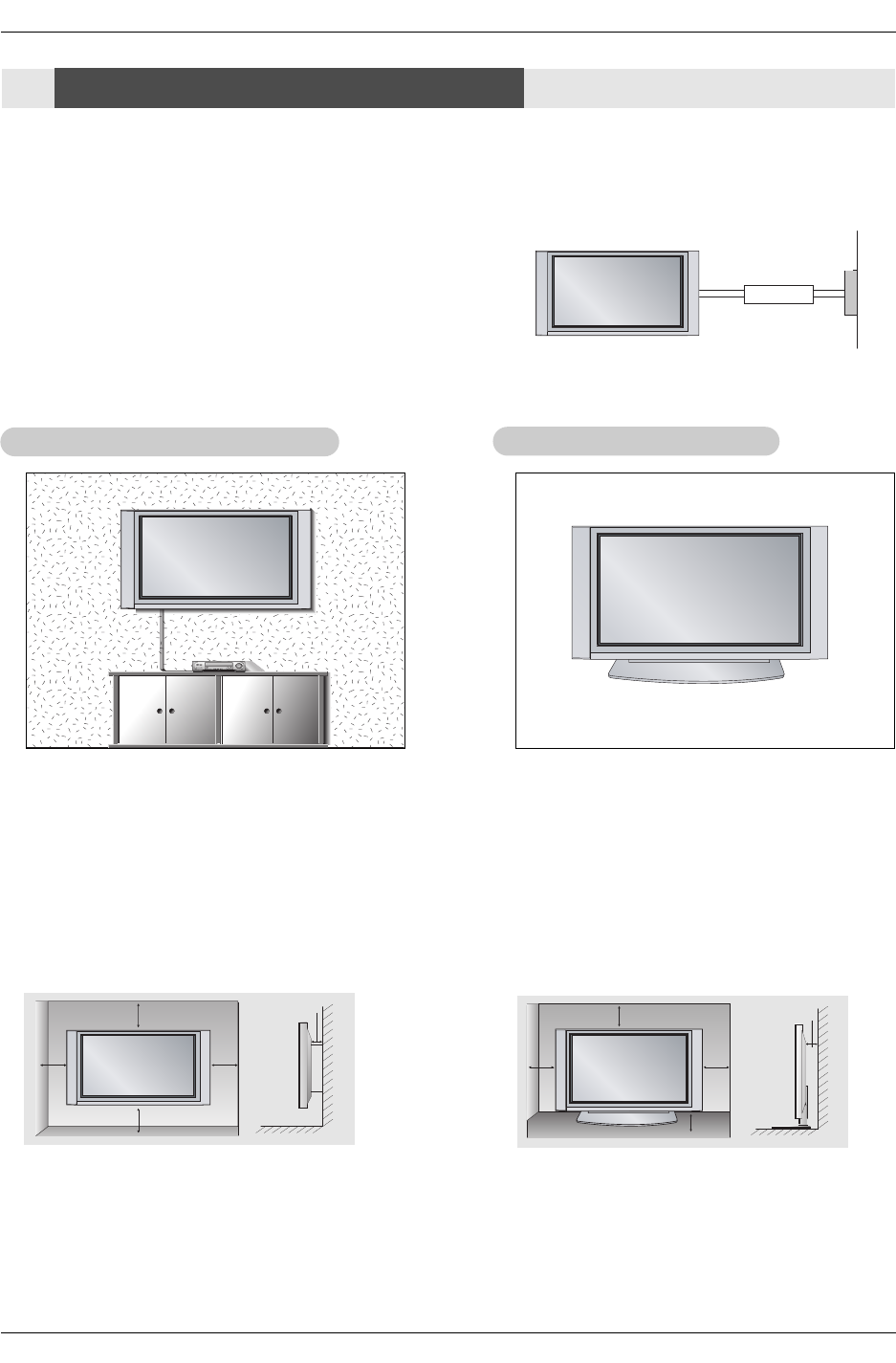
W
Wall Mount: Horizontal installation
all Mount: Horizontal installation
For proper ventilation, allow a clearance of 4” on each
side and 2” from the wall. Detailed installation instruc-
tions are available from your dealer, see the optional
Wall Mounting Bracket Installation.
4 inches
4 inches
2.36 inches
4 inches
2 inches
Desktop Pedestal Installation
Desktop Pedestal Installation
For proper ventilation, allow a clearance of 4” on each
side and the top, 2.36” on the bottom, and 2” from the
wall. Detailed installation instructions are included in
the optional Desktop Stand Installation.
•The TV can be installed in various ways such as on a wall, or on a desktop etc.
•The TV is designed to be mounted horizontally.
Installation Instructions
Installation Instructions
Owner’s Manual
Installation
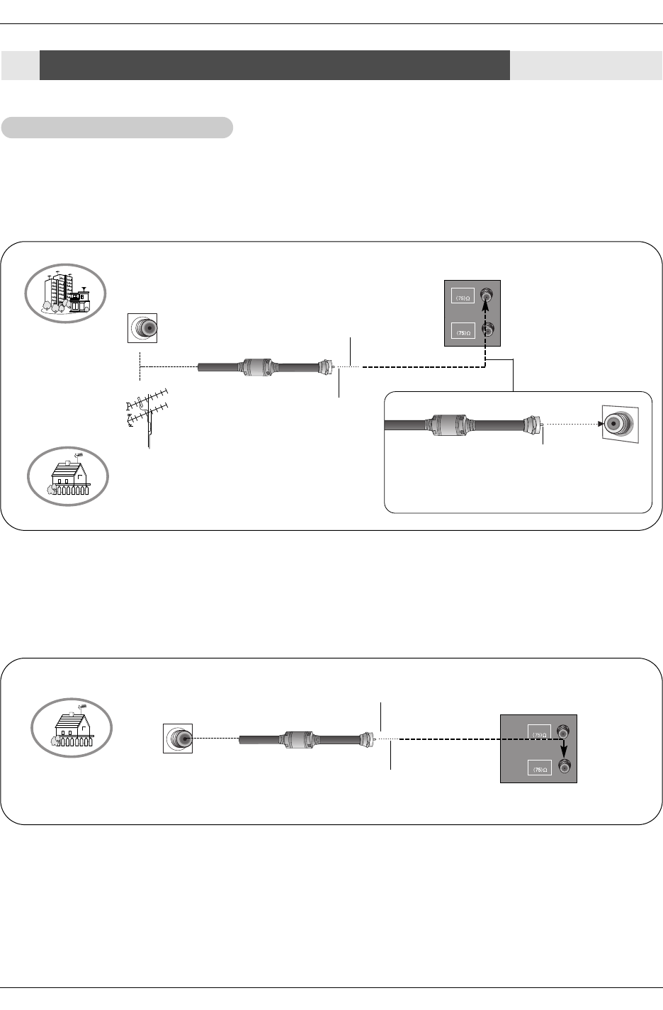
- Wall Antenna Socket or Outdoor Antenna without a Cable Box Connections
- For optimum picture quality, adjust antenna direction if needed.
1. Analog and Digital TV signals provided on antenna
2. Analog and Digital TV signals provided on cable
ANTENNA
CABLE
Multi-family Dwellings/Apartments
(Connect to wall antenna socket)
Single-family Dwellings /Houses
(Connect to wall jack for outdoor antenna)
Outdoor
Antenna
Wall Antenna
Socket
VHF Antenna
UHF Antenna
RF Coaxial Wire (75 ohm)
Bronze Wire
Turn clockwise to tighten.
Bronze Wire
Be careful not to bend the bronze wire when
connecting the antenna.
Bronze Wire
Cable TV Wall
Jack RF Coaxial Wire (75 ohm)
ANTENNA
CABLE
External Equipment Connections
External Equipment Connections
Antenna or Cable Connection
Antenna or Cable Connection
Bronze Wire
Operating Guide
Installation
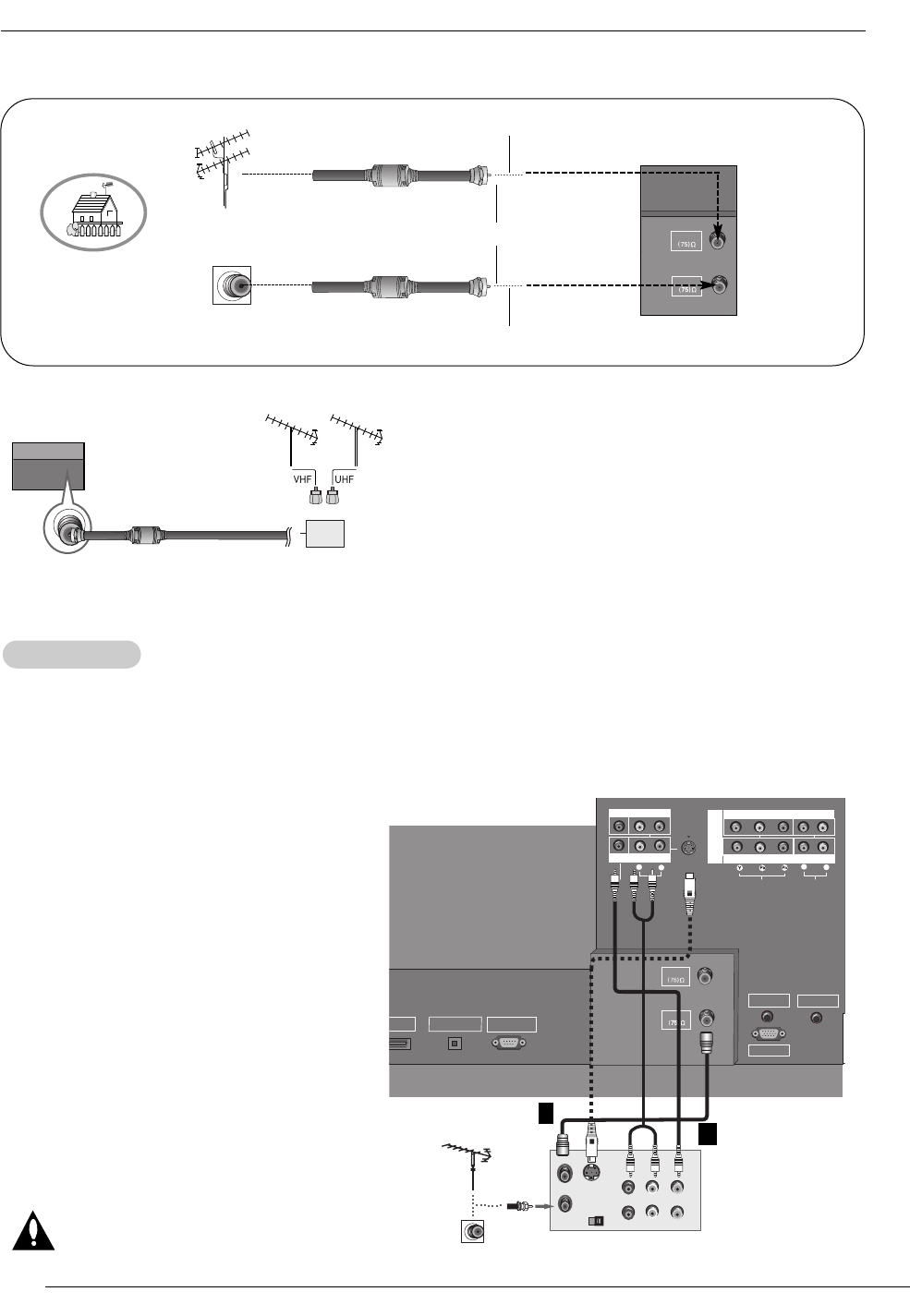
- To avoid picture noise (interference), leave an adequate distance between the VCR and TV
- Use the ISM Method (on the Option menu) feature to avoid having a fixed image remain on the screen for a long period of time.
If the 4:3 picture format is used; the fixed images on the sides of the screen may remain visible on the screen.
Connection Option 1
Set VCR output switch to channel 3 or 4 and
then tune the TV to the same channel number.
Connection Option 2
1. Connect the audio and video cables from the
VCR's output jacks to the TV input jacks, as
shown in the figure.
When connecting the TV to VCR, match the
jack colors (Video = yellow, Audio Left = white,
and Audio Right = red).
If you connect an S-VIDEO output from VCR to
the S-VIDEO input, the picture quality is
improved; compared to connecting a regular
VCR to the Video input.
2. Insert a video tape into the VCR and press
PLAY on the VCR. (Refer to the VCR owner’s
manual.)
3. Select the input source with using the
TV/VIDEO button on the remote control. Note
that this TV finds the connected input sources
automatically for Video, Front Video and
Component 1-2. It is presumed that RGB and
HDMI/DVI sources are connected.
Do not connect to both Video and
S-Video at the same time.
VCR Setup
VCR Setup
AUDIO
R
L
VIDEO
COMPONENT INPUT 1
R
L
(MONO)
COMPONENT INPUT 2
MONITOR OUTPUT
A/V INPUT
VIDEO
AUDIO
S-VIDEO
DVD
/DTV
INPUT
AUDIO INPUT
REMOTE CONTROL
RGB INPUT
ANTENNA
CABLE
DMI /DVI
DIGITAL AUDIO
OPTICAL OUTPUT
(CONTROL/SERVICE)
RS-232C INPUT
S-VIDEO OUT
IN
(R) AUDIO (L) VIDEO
34
OUTPUT
SWITCH
ANT OUT
ANT IN
VCR Rear
1
2
•To improve the picture quality in a poor signal area,
please purchase a signal amplifier and install properly.
•If the antenna needs to be split for two TV’s, install a “2-
Way Signal Splitter” in the connections.
•If the antenna is not installed properly, contact your deal-
er for assistance.
Signal
Amplifier
3. Analog and Digital TV signals provided on cable and antenna
Antenna
RF Coaxial Wire (75 ohm)
Bronze Wire
Turn clockwise to tighten.
Cable TV Wall
Jack RF Coaxial Wire (75 ohm)
ANTENNA
CABLE
Bronze Wire
Owner’s Manual
Installation
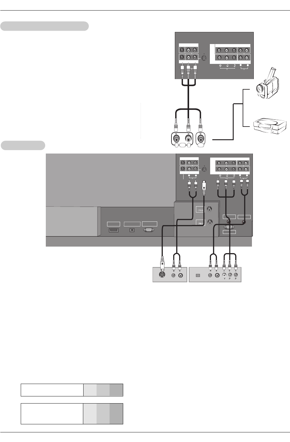
•Component Input ports
To get better picture quality, connect a DVD player to the compo-
nent input ports as shown below.
How to connect
Connect the audio and video cables from the external equip-
ment's output jacks to the TV input jacks, as shown in the
figure.
When connecting the TV to external equipment, match the
jack colors (Video = yellow, Audio Left = white, and Audio
Right = red).
How to use
1. Select the input source with using the TV/VIDEO button on
the remote control. Note that this TV finds the connected
input sources automatically for Video, Front Video and
Component 1-2. It is presumed that RGB and HDMI/DVI
sources are connected.
2. Operate the corresponding external equipment.
Component ports
on the TV YPBPR
Video output ports
on DVD player
Y
Y
Y
Y
Pb
B-Y
Cb
PB
Pr
R-Y
Cr
PR
How to connect
1. Connect the DVD video outputs (Y, PB, PR) to the COMPONENT (Y, PB, PR) INPUT jacks on the TV and connect the DVD
audio outputs to the AUDIO INPUT jacks on the TV, as shown in the figure.
2. If your DVD only has an S-Video output jack, connect this to the S-VIDEO input on the TV and connect the DVD audio outputs
to the AUDIO INPUT jacks on the TV, as shown in the figure.
Note: If your DVD player does not have component video output, use S-Video.
How to use
1. Turn on the DVD player, insert a DVD.
2. Use the TV/VIDEO button on the remote control to select Component 1 or Component 2. (If connected to S-VIDEO, select
the Video or Front Video external input source.)
3. Refer to the DVD player's manual for operating instructions.
External
External A/V Source Setup
A/V Source Setup
DVD Setup
DVD Setup
AUDIO
R
L
VIDEO
COMPONENT INPUT 1
R
L
(MONO)
COMPONENT INPUT 2
MONITOR OUTPUT
A/V INPUT
VIDEO
AUDIO
S-VIDEO
DVD
/DTV
INPUT
AUDIO INPUT
REMOTE CONTROL
RGB INPUT
ANTENNA
CABLE
(CONTROL/SERVICE)
RS-232C INPUT
RL
AUDIO
VIDEO
AUDIO
R
L
VIDEO
COMPONENT INPUT 1
R
L
(MONO)
COMPONENT INPUT 2
MONITOR OUTPUT
A/V INPUT
VIDEO
AUDIO
S-VIDEO
DVD
/DTV
INPUT
AUDIO INPUT
REMOTE CONTROL
RGB INPUT
ANTENNA
CABLE
HDMI /DVI
DIGITAL AUDIO
OPTICAL OUTPUT
(CONTROL/SERVICE)
RS-232C INPUT
(R) AUDIO (L)
S-VIDEO
BR
(R) AUDIO (L)
DIGITAL AUDIO
OPTICAL
DVD
or
Camcorder
Video Game
Device
or
Operating Guide
Installation
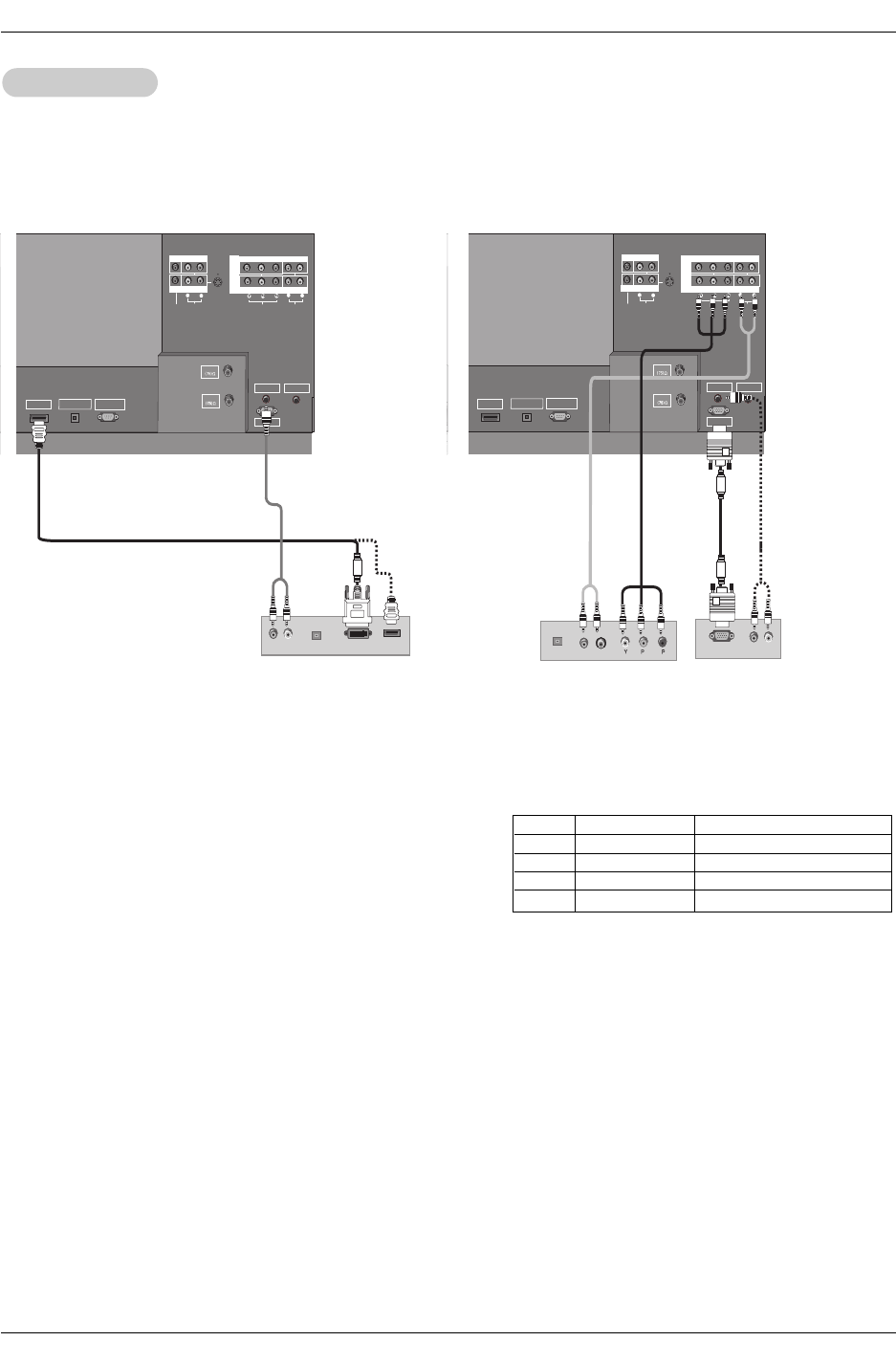
- This TV can receive Digital Over-the-air/Cable signals without an external digital set-top box. However, if you do receive Digital
signals from a digital set-top box or other digital external device, refer to the figure as shown below.
- This TV supports HDCP (High-bandwidth Digital Contents Protection) protocol for Digital Contents (480p,720p,1080i).
How to connect
Use the TV’s COMPONENT (Y, PB, PR) INPUT, RGB or HDMI/DVI jack
for video connections, depending on your set-top box connector. Then,
make the corresponding audio connections.
How to use
1. Turn on the digital set-top box. (Refer to the owner’s manual for the
digital set-top box.)
2. Use TV/VIDEO on the remote control to select Component 1,
Component 2, RGB-DTV, or HDMI/DVI source.
HDSTB Setup
HDSTB Setup
AC I
AUDI O
R
L
VIDEO
COMPONENT INPUT 1
R
L
(MONO)
COMPONENT INPUT 2
MONITOR OUTPUT
A/V INPUT
VIDEO
AUDI O
S-VIDEO
DVD
/DTV
INPUT
AUDIO INPUT
REMOTE CONTROL
RGB INPUT
ANTENNA
CABLE
HDMI /DVI
DIGITAL AUDIO
OPTICAL OUTPUT
(CONTROL/SERVICE)
RS-232C INPUT
(R) AUDIO (L)
DVI-DTV OUTPUT
DIGITAL AUDIO
OPTICAL
HDMI-DTV OUTPUT
AUDI O
R
L
VIDEO
COMPONENT INPUT 1
R
L
(MONO)
COMPONENT INPUT 2
MONITOR OUTPUT
A/V INPUT
VIDEO
AUDIO
S-VIDEO
DVD
/DTV
INPUT
AUDIO INPUT
REMOTE CONTROL
RGB INPUT
ANTENNA
CABLE
HDMI /DVI
DIGITAL AUDIO
OPTICAL OUTPUT
(CONTROL/SERVICE)
RS-232C INPUT
(R) AUDIO (L)
RGB-DTV OUTPUT
BR
(R) AUDIO (L)
DIGITAL AUDIO
OPTICAL
Digital Set-top Box
or
Signal
480i
480p
720p
1080i
Component 1/2
Yes
Yes
Yes
Yes
RGB-DTV , HDMI/DVI
No
Yes
Yes
Yes
or

Owner’s Manual
<When the PC supports DVI>
How to connect
1. Connect the PC to HDMI/DVI port of this TV with an HDMI-to-DVI cable(not supplied with this product).
2. If the PC(or the sound card of the PC) has an analog audio output connector, connect the PC's audio output to AUDIO INPUT
port located on the upper side of RGB INPUT port.
How To Use
1. To get the best picture quality, adjust the PC graphics card to 1024x768, 60Hz.
2. Select HDMI/DVI input source in input source option of SETUP menu.(Refer to P.25)
TV/VIDEO button is also available for this purpose.
3. Check the image on your TV. There may be noise associated with the resolution, vertical pattern, contrast or brightness in PC
mode. If noise is present, change the PC output to another resolution, change the refresh rate to another rate or adjust the
brightness and contrast on the VIDEO menu until the picture is clear. If the refresh rate of the PC graphic card can not be
changed, change the PC graphic card or consult the manufacturer of the PC graphic card.
<When the PC supports RGB>
How to connect
1. Connect the PC to RGB INPUT port of this TV with a RGB cable(not supplied with this product).
2. If the PC(or the sound card of the PC) has an analog audio output connector, connect the PC's audio output to AUDIO INPUT
port located on the right side of RGB INPUT port.
How To Use
1. To get the best picture quality, adjust the PC graphics card to 1024x768, 60 Hz.
2. Select RGB-PC input source in input source option of SETUP menu.(Refer to P.25)
Once you select RGB-PC in main input option of SETUP menu, TV/VIDEO button is also available for this purpose.
3. Check the image on your TV. There may be noise associated with the resolution, vertical pattern, contrast or brightness in PC
mode. If noise is present, change the PC output to another resolution, change the refresh rate to another rate or adjust the
brightness and contrast on the VIDEO menu until the picture is clear. If the refresh rate of the PC graphic card can not be
changed, change the PC graphic card or consult the manufacturer of the PC graphic card.
720x400
640x350
Installation
PC Setup
PC Setup
- This TV provides Plug and Play capability, meaning that the PC adjusts automatically to the TV's settings.
- The TV perceives 640x480, 60Hz as DTV 480p based on the PC graphic card, change the screen scanning rate for the graphic
card accordingly.
800x600
70.08
70.09
59.94
72.80
75.00
35.156
37.879
48.077
46.875
48.363
56.476
60.023
56.25
60.31
72.18
75.00
60.00
70.06
75.02
Vertical
Frequency(Hz) Resolution Horizontal
Frequency(KHz)
Vertical
Frequency(Hz)
1024x768
Resolution
640x480
Horizontal
Frequency(KHz)
31.469
31.468
31.469
37.861
37.500
Monitor Display Specifications (RGB-PC )
Operating Guide
Installation
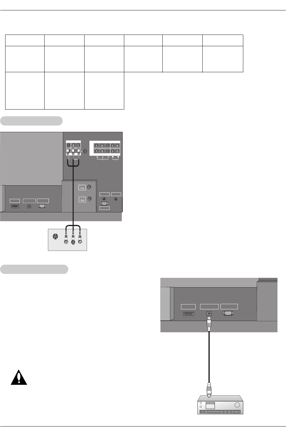
Send the TV’s audio to external audio equipment (stereo system) via
the Digital Audio Output (Optical) port.
How to connect
1. Connect one end of an optical cable to the TV Digital Audio
(Optical) Output port.
2. Connect the other end of the optical cable to the digital audio (opti-
cal) input on the audio equipment.
See the external audio equipment instruction manual for operation.
Note: When connecting with external audio equipments, such as
amplifers or speakers, please turn the TV speakers off.(Refer to
p.28)
Caution: Do not look into the optical output port.
Looking at the laser beam may damage
your vision.
Digital
Digital Audio Output
Audio Output
HDMI /DVI
DIGITAL AUDIO
OPTICAL OUTPUT
(CONTROL/SERVICE)
RS-232C INPUT
The TV has a special signal output capability which allows you to
hook up a second TV or monitor.
Connect the second TV or monitor to the TV’s MONITOR OUTPUT.
See the Operating Manual of the second TV or monitor for further
details regarding that device’s input settings.
Notes:
• Component, RGB-PC/RGB-DTV, HDMI/DVI, DTV input sources
cannot be used for Monitor out.
• When connecting with external audio equipments, such as amplif-
ers or speakers, please turn the TV speakers off.(Refer to p.28)
• We recommend to use the video and audio output jacks for VCR
recording.
AUDIO
R
L
VIDEO
COMPONENT INPUT 1
R
L
(MONO)
COMPONENT INPUT 2
MONITOR OUTPUT
A/V INPUT
VIDEO
AUDIO
S-VIDEO
DVD
/DTV
INPUT
AUDIO INPUT
REMOTE CONTROL
RGB INPUT
ANTENNA
CABLE
HDMI /DVI
DIGITAL AUDIO
OPTICAL OUTPUT
(CONTROL/SERVICE)
RS-232C INPUT
S-VIDEO IN
(L) AUDIO (R)
VIDEO
Monitor Out Setup
Monitor Out Setup
Resolution
640x480
800x600
Horizontal
Frequency(KHz)
31.469
37.861
37.500
35.156
37.879
48.077
46.875
59.94
72.80
75.00
56.25
60.31
72.18
75.00
48.363
56.476
60.023
60.00
70.06
75.02
Vertical
Frequency(Hz) Resolution Horizontal
Frequency(KHz)
Vertical
Frequency(Hz)
1024x768
Monitor Display Specifications (HDMI/DVI Mode)

Owner’s Manual
Installation
- HDMITM, the HDMI logo and High-Definition Multimedia Interface is a trademark or registered trademark of HDMI Licensing."
- This TV can receive the High-Definition Multimedia Interface(HDMI) or the Digital Visual Interface(DVI).
- This TV supports HDCP(High-bandwidth Digital Contents Protection) Protocol for 720x480p, 1280x720p, and 1920x1080i resolu-
tion.
- When you connect this TV with a source device(DVD player, Set Top Box or PC) supporting Auto HDMI/DVI function, the output
resolution of the source device will be automatically set to 1280x720p.
- If the source device does not support Auto HDMI/DVI, you need to set the output resolution appropriately.
To get the best picture quality, adjust the DVD Player or Set Top Box's output resolution to 1280x720p, and the PC graphics card's
output resolution to 1024x768, 60Hz.
- If the source device has an HDMI output, no other audio connection is necessary because HDMI-to-HDMI connection includes
both video and audio.
- If the source device has a DVI output and no HDMI output, a separated audio connection is necessary.
<When the source device(DVD player or Set Top Box) supports HDMI>
How To Connect
1. Connect the source device to HDMI/DVI port of this TV with an HDMI cable(not supplied with this product).
2. No separated audio connection is necessary.
How To Use
- If the source device supports Auto HDMI function, the output resolution of the source device will be automatically set to 1280x720p.
- If the source device does not support Auto HDMI, you need to set the output resolution appropriately.
To get the best picture quality, adjust the output resolution of the source device to 1280x720p.
- Select HDMI/DVI input source in input source option of SETUP menu.(Refer to P.25)
TV/VIDEO button is also available for this purpose.
<When the source device(DVD player or Set Top Box) supports DVI>
How To Connect
1. Connect the source device to HDMI/DVI port of this TV with a HDMI-to-DVI cable(not supplied with this product).
2. A separated audio connection is necessary.
3. If the source device has an analog audio output connector, connect the PC's audio output to AUDIO INPUT port located on the
upper side of RGB INPUT port.
How To Use
- If the source device supports Auto DVI function, the output resolution of the source device will be automatically set to 1280x720p.
- If the source device does not support Auto DVI, you need to set the output resolution appropriately.
To get the best picture quality, adjust the output resolution of the source device to 1280x720p.
- Select HDMI/DVI input source in input source option of SETUP menu.(Refer to P.25)
TV/VIDEO button is also available for this purpose.
HDMI
HDMI
Operating Guide
Installation
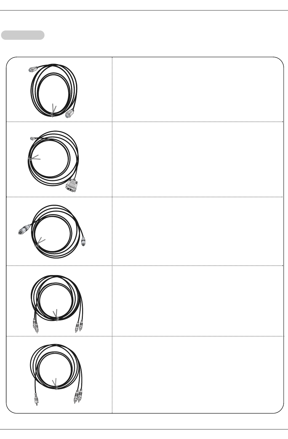
Cable sample
HDMI Cable
(not supplied with the product)
HDMI to DVI Cable
(not supplied with the product)
Fiber Optic Digital Audio Cable
(not supplied with the product)
Analog Audio Cable(RCA type)
(not supplied with the product)
Analog Audio Cable(Stereo to RCA type)
(not supplied with the product)
Reference
Reference
Owner’s Manual
Installation
How to use
1. Connect the HDMI/DVI Source Devices(DVD Player or Set Top Box or PC) and the TV SET.
2. Turn on the display by pressing the POWER button on the TV SET and HDMI/DVI Source Devices remote control.
3. Select HDMI/DVI Input source in input source option of SETUP menu.(Refer to P.25)
4. Check the image on your TV SET. There may be noise associated with the resolution, vertical pattern, contrast or brightness in
HDMI/DVI Source Devices. If noise is present, change the HDMI/DVI Source Devices to another resolution, change the refresh
rate or adjust the brightness and contrast on the menu until the picture is clear. If the refresh rate of the PC graphics card can
not changed, change the PC graphics card or consult the manufacturer of the PC graphics card.
Notes:
- Depending on the graphics card, DOS mode may not work if you use a HDMI to DVI Cable.
- Avoid keeping a fixed image on the TV SET screen for a long period of time. The fixed image may become permanently imprint-
ed on the screen. Use the Orbiter screen saver when possible.
- When Source Devices connected HDMI/DVI Input, output PC Resolution(VGA, SVGA, XGA), Position, Size may not fit to
Screen. As shown the lower picture, press the ADJUST button to adjust the screen Position of TV SET and contact an PC
graphics card service center.
- When Source Devices connected HDMI/DVI Input output TV SET Resolution(480p, 720p, 1080i), TV SET Display fit EIA/CEA-
861-B Specification to Screen. If not, refer to the Manual of HDMI/DVI Source Devices or contact your service center.
- In case HDMI/DVI Source Devices is not connected Cable or poor cable connection, "NO SIGNAL" OSD display in HDMI/DVI
Input. And In case of, Video Resolution not supported TV SET output in HDMI/DVI Source Devices, "INVALID FORMAT" OSD
display. Refer to the Manual of HDMI/DVI Source Devices or contact your service center.
Close
POSITION GG
SIZE
PHASE
RESET
Adjust
DD
FFGG
EE
In This Mode, the Supported TV SET Resolution Specification
- 1920 x 1080 I @ 59.94Hz / 60Hz, 16:9
- 1280 x 720 P @ 59.94Hz / 60Hz, 16:9(preferred format)
- 720 x 480 P @ 59.94Hz / 60Hz, 16:9
- 720 x 480 P @ 59.94Hz / 60Hz, 4:3
In This Mode, the Supported PC Resolution Specification
- 640 x 480 @ 60Hz
- 640 x 480 @ 72Hz
- 640 x 480 @ 75Hz
- 800 x 600 @ 56Hz
- 800 x 600 @ 60Hz
- 800 x 600 @ 72Hz
- 800 x 600 @ 75Hz
- 1024 x 768 @ 60Hz(preferred format)
- 1024 x 768 @ 70Hz
- 1024 x 768 @ 75Hz
PC mode
Owner’s Manual
Operation
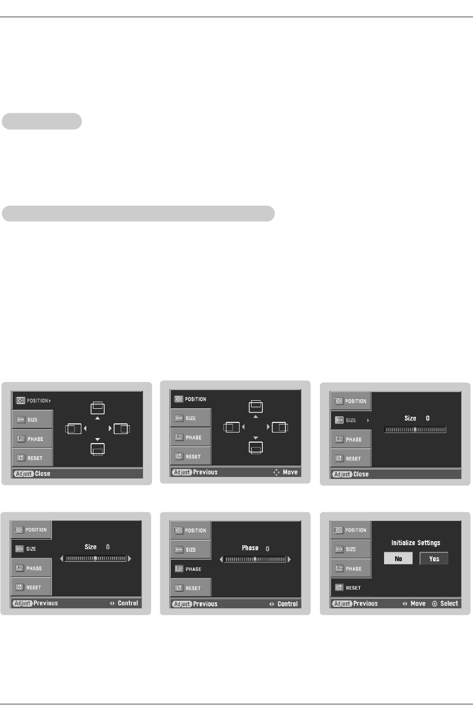
• When RGB connect to PC input and select the RGB-PC, this function is used.
• When HDMI/DVI connect to PC input and select HDMI/DVI input, this function is used.
• In RGB-DTV mode, SIZE and PHASE is not available.
•After connecting RGB-PC or HDMI/DVI to PC input and checking the screen quality.
- Display PC Adjust Menu using ADJUST button.
- Position : Adjust the screen position. After displaying the Adjust, select the screen position.
- Size : Adjust the screen size.
- Phase : Adjust the phase of Pixel clock.
In HDMI/DVI-PC mode, PHASE is not available.
- Reset : Initializating Position, Size, Phase adjustment .
Operation
Operation
Adjustment for screen Position, Size, Phase, Reset
Adjustment for screen Position, Size, Phase, Reset
Screen Setup for PC mode
Operating Guide
External Control Device Setup
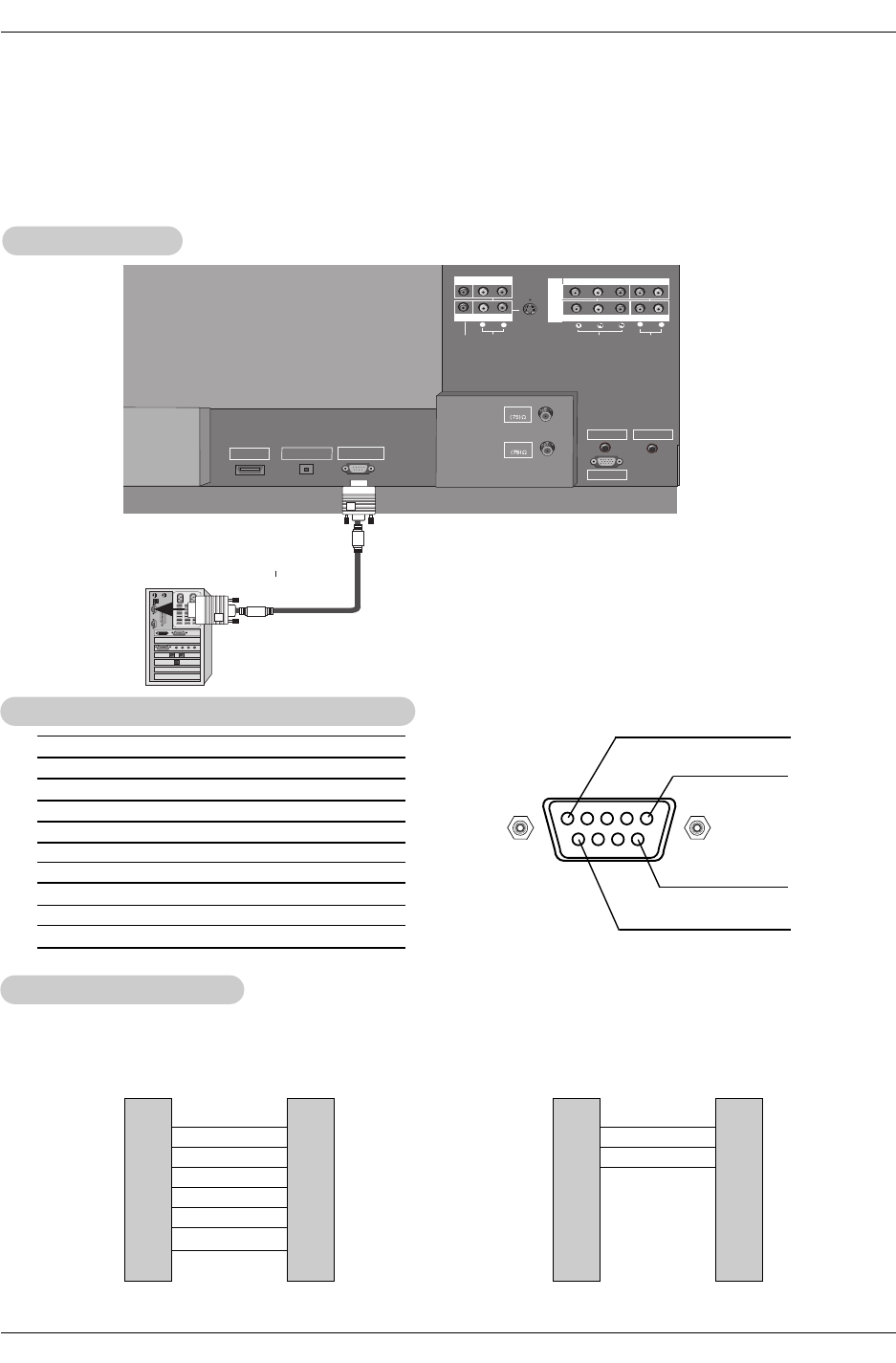
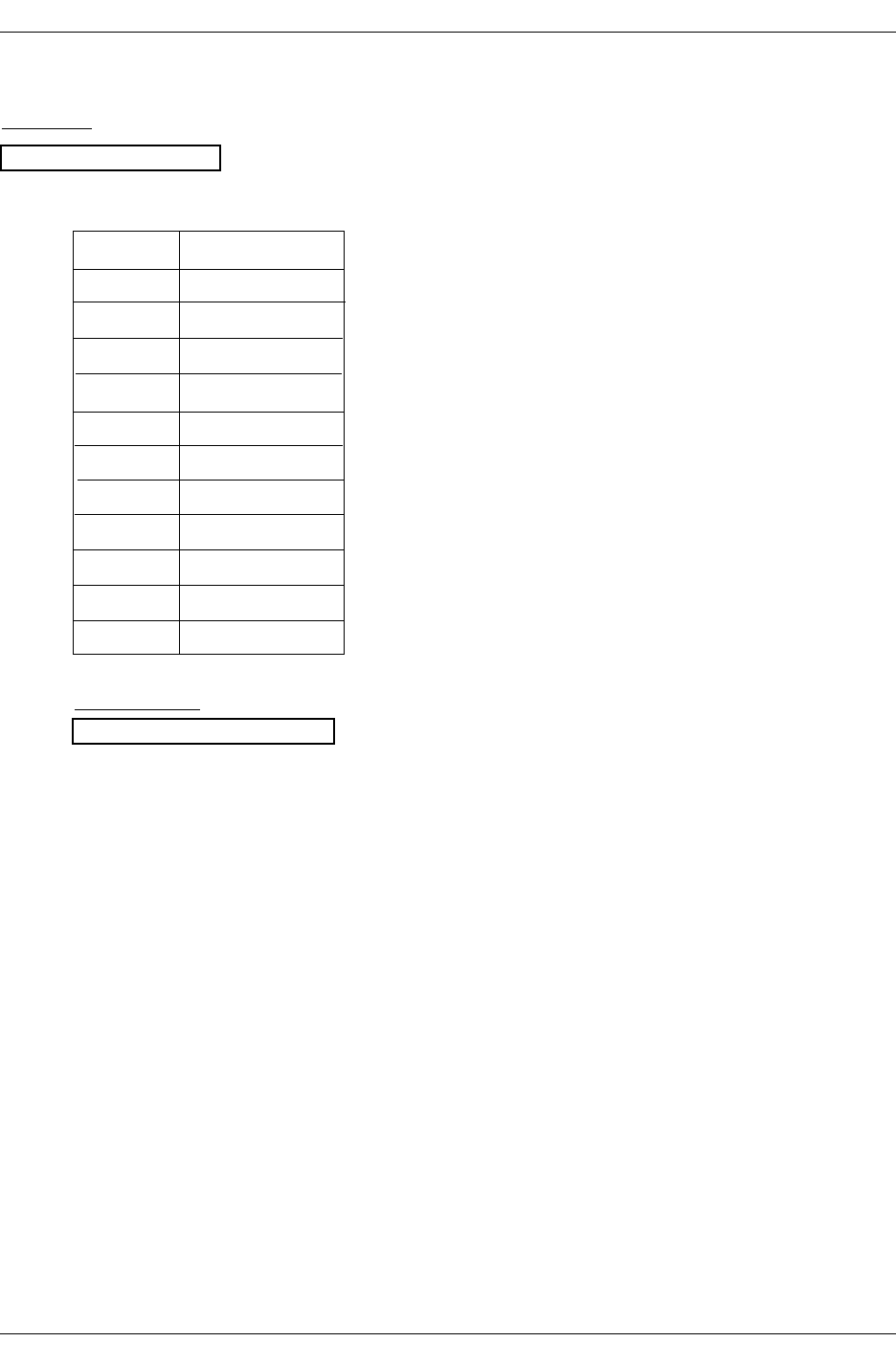
No. Pin Name
1 No connection
2 RXD (Receive data)
3 TXD (Transmit data)
4 DTR (DTE side ready)
5 GND
6 DSR (DCE side ready)
7 RTS (Ready to send)
8 CTS (Clear to send)
9 No Connection
1
5
6
9
2
3
5
4
6
7
8
RXD
TXD
GND
DTR
DSR
RTS
CTS
TXD
RXD
GND
DSR
DTR
CTS
RTS
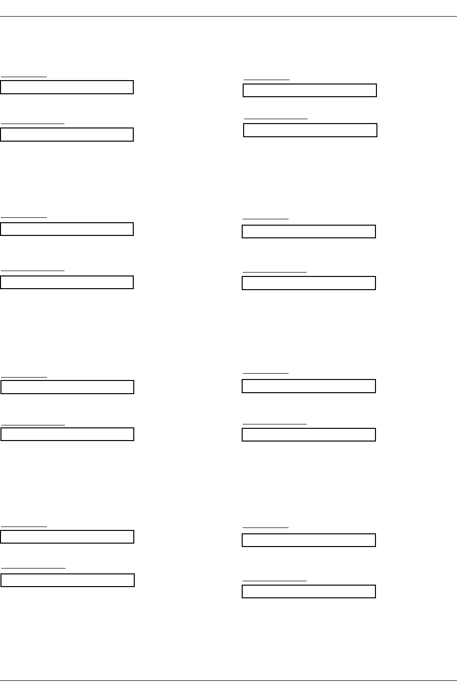
PC
7-Wire Configurations
(Standard RS-232C cable)
D-Sub 9
3
2
5
6
4
8
7
PDP
D-Sub 9
2
3
5
4
6
7
8
RXD
TXD
GND
DTR
DSR
RTS
CTS
TXD
RXD
GND
DTR
DSR
RTS
CTS
PC
3-Wire Configurations
(Not standard)
D-Sub 9
3
2
5
4
6
7
8
PDP
D-Sub 9
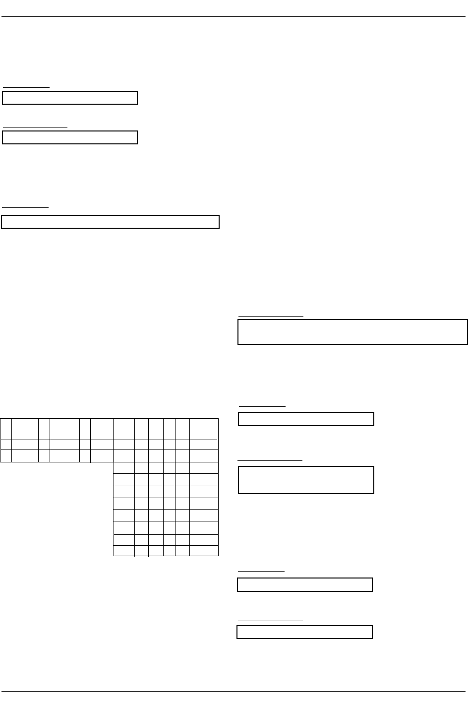
- Connect the RS-232C input jack to an external control device (such as a computer or an A/V control system)
and control the Monitor’s functions externally.
- Connect the serial port of the control device to the RS-232C jack on the Monitor back panel.
- RS-232C connection cables are not supplied with the Monitor.
T
Type of Connector; D-Sub 9-Pin Male
ype of Connector; D-Sub 9-Pin Male
RS-232C Configurations
RS-232C Configurations
External Control Device Setup
External Control Device Setup
RS-232C Setup
RS-232C Setup
AUDIO
R
L
VIDEO
COMPONENT INPUT 1
R
L
(MONO)
COMPONENT INPUT 2
MONITOR OUTPUT
A/V INPUT
VIDEO
AUDIO
S-VIDEO
DVD
/DTV
INPUT
AUDIO INPUT
REMOTE CONTROL
RGB INPUT
ANTENNA
CABLE
HDMI /DVI
DIGITAL AUDIO
OPTICAL OUTPUT
(CONTROL/SERVICE)
RS-232C INPUT
PC
Owner’s Manual
External Control Device Setup
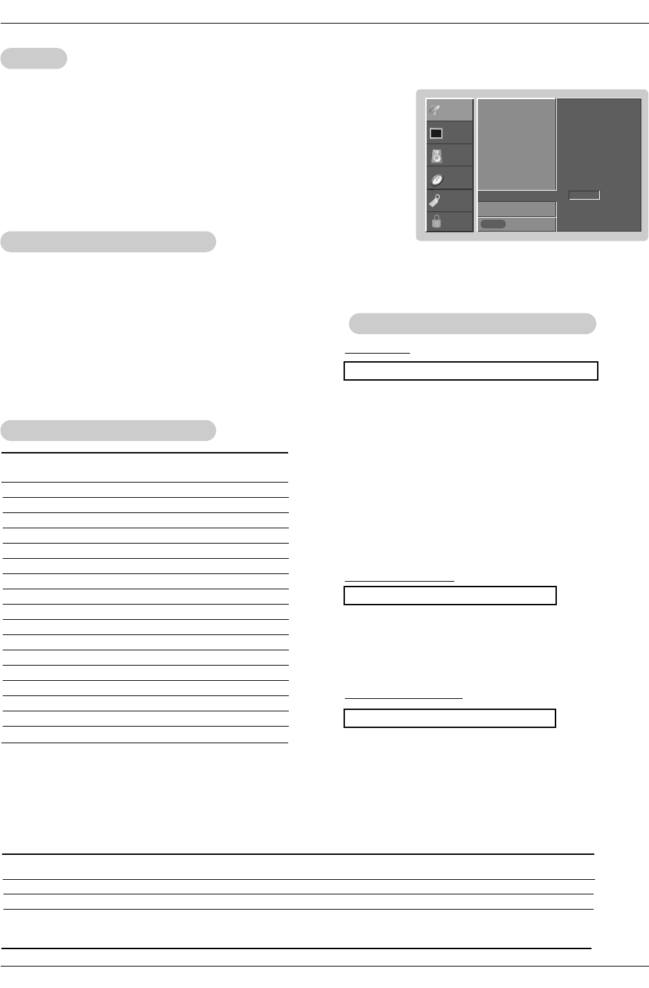
Set ID
Set ID
Use this function to specify a monitor ID number.
Refer to ‘Real Data Mapping’. See page 44.
• Baud rate : 9600 bps (UART)
• Data length : 8 bits
• Parity : None
* Use a crossed (reverse) cable.
• Stop bit : 1 bit
• Communication code : ASCII code
Communication Parameters
Communication Parameters
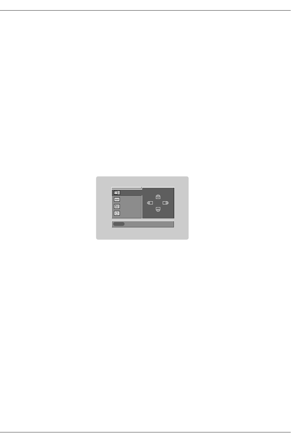
1. Press the MENU button and then use DD /EEbutton to select the SETUP menu.
2. Press the GGbutton and then use DD /EEbutton to select SET ID.
3. Press the GGbutton and then use DD /EEbutton to adjust SET ID to choose the
desired monitor ID number. The adjustment range of SET ID is 1 ~ 99.
4. Press EXIT button to return to TV viewing or press MENU button to return to the
previous menu.
Transmission
* [Command 1]: First command to control the set.(j,k,m or x)
* [Command 2]: Second command to control the set.
* [Set ID]: You can adjust the set ID to choose desired monitor
ID number in Setup menu. Adjustment range is 1
~ 99. When selecting Set ID ‘0’, every connected
the TV is controlled. Set ID is indicated as decimal
(1~99) on menu and as Hexa decimal (0x0~0x63)
on transmission/receiving protocol.
* [DATA]: To transmit command data.
Transmit ‘FF’data to read status of command.
* [Cr]: Carriage Return
ASCII code ‘0x0D’
* [ ]: ASCII code ‘space (0x20)’
[Command1][Command2][ ][Set ID][ ][Data][Cr]
T
Transmission / Receiving Protocol
ransmission / Receiving Protocol
OK Acknowledgement
* The Monitor transmits ACK (acknowledgement) based on
this format when receiving normal data. At this time, if the
data is data read mode, it indicates present status data. If
the data is data write mode, it returns the data of the PC
computer.
[Command2][ ][Set ID][ ][OK][Data][x]
Error Acknowledgement
* The Monitor transmits ACK (acknowledgement) based on
this format when receiving abnormal data from non-viable
functions or communication errors.
[Command2][ ][Set ID][ ][NG][Data][x]
Data 1: Illegal Code
2: Not supported function
3: Wait more time
01. Power k a 0 ~ 1
02. Input Select k b 0 ~ 8
03. Aspect Ratio k c *
04. Screen Mute k d 0 ~ 1
05. Volume Mute k e 0 ~ 1
06. Volume Control k f 0 ~ 64
07. Contrast k g 0 ~ 64
08. Brightness k h 0 ~ 64
09. Color k i 0 ~ 64
10. Tint k j 0 ~ 64
11. Sharpness k k 0 ~ 64
12. OSD Select k l 0 ~ 1
13.
Remote Control Lock Mode
k m 0 ~ 1
14. Treble k r 0 ~ 64
15. Bass k s 0 ~ 64
16. Balance k t 0 ~ 64
17. Color Temperature k u 0 ~ 2
COMMAND 1 COMMAND 2 DATA
(Hexadecimal)
Command Reference List
Command Reference List
18. Channel Tuning m a physical/program high major/program low major low minor high minor low attribute
19. Channel Add/Del m b 00 ~ 01
21. Input Select x b *
COM-
MAND 2
COM-
MAND 1
DATA 0
(Hexadecimal)
DATA 1
(Hexadecimal)
DATA 2
(Hexadecimal)
DATA 3
(Hexadecimal)
DATA 4
(Hexadecimal)
DATA 5
(Hexadecimal)
SETUP
VIDEO
AUDIO
TIME
OPTION
LOCK Previous
EZ Scan
Manual Scan
Channel Edit GG
DTV Signal
Channel Label
Input Source
Input Label
Set ID GG
MENU
1
Operating Guide
External Control Device Setup
02. Input Select (Command2:b) (Main Picture Input)
GTo select input source for the Monitor.
Transmission
Data 0: DTV
1: Analog
2: Video
3: Front Video
4: Component 1
5: Component 2
6: RGB-DTV
7: RGB-PC
8: HDMI/DVI
Date 1: 4:3
2: 16:9
3: Horizon
4: Zoom 1
5: Zoom 2
6: Set by program
10: Cinema Zoom (1)
1F: Cinema Zoom (16)
[k][b][ ][Set ID][ ][Data][Cr]
Acknowledgement
[b][ ][Set ID][ ][OK][Data][x]
01. Power (Command2:a)
GTo control Power On/Off of the Monitor.
Transmission
Data 0 : Power Off 1 : Power On
[k][a][ ][Set ID][ ][Data][Cr]
Acknowledgement
[a][ ][Set ID][ ][OK][Data][x]
* In a like manner, if other functions transmit ‘FF’data
based on this format, Acknowledgement data feedback
presents status about each function.
* Real data mapping
0 : Step 0
A : Step 10 (SET ID 10)
F : Step 15 (SET ID 15)
10 : Step 16 (SET ID 16)
63 : Step 99 (SET ID 99)
64 : Step 100
05. Volume Mute (Command2:e)
GTo control volume mute on/off.
You can also adjust mute using the MUTE button on
remote control.
Transmission
Data 0 : Volume mute off (Volume on)
1 : Volume mute on (Volume off)
[k][e][ ][Set ID][ ][Data][Cr]
Acknowledgement
[e][ ][Set ID][ ][OK][Data][x]
03. Aspect Ratio (Command2:c) (Main picture format)
GTo adjust the screen format.
You can also adjust the screen format using the RATIO
button on remote control or in the Option menu.
Transmission
[k][c][ ][Set ID][ ][Data][Cr]
Acknowledgement
[c][ ][Set ID][ ][OK][Data][x]
04. Screen Mute (Command2:d)
GTo select screen mute on/off.
Transmission
Data 0 : Screen mute off (Picture on)
1 : Screen mute on (Picture off)
[k][d][ ][Set ID][ ][Data][Cr]
Acknowledgement
[d][ ][Set ID][ ][OK][Data][x]
06. Volume Control (Command2:f)
GTo adjust volume.
You can also adjust volume with the volume buttons
on remote control.
Transmission
Data Min : 0 ~ Max : 64
•Refer to ‘Real data mapping’as shown below.
[k][f][ ][Set ID][ ][Data][Cr]
Acknowledgement
[f][ ][Set ID][ ][OK][Data][x]
07. Contrast (Command2:g)
GTo adjust screen contrast.
You can also adjust contrast in the Video menu.
Transmission
Data Min : 0 ~ Max : 64
•Refer to ‘Real data mapping’as shown below.
[k][g][ ][Set ID][ ][Data][Cr]
Acknowledgement
[g][ ][Set ID][ ][OK][Data][x]
08. Brightness (Command2:h)
GTo adjust screen brightness.
You can also adjust brightness in the Video menu.
Transmission
Data Min : 0 ~ Max : 64
•Refer to ‘Real data mapping’as shown below.
[k][h][ ][Set ID][ ][Data][Cr]
Acknowledgement
[h][ ][Set ID][ ][OK][Data][x]
Owner’s Manual
External Control Device Setup
09. Color (Command2:i)
GTo adjust the screen color.
You can also adjust color in the Video menu.
Transmission
Data Min : 0 ~ Max : 64
•Refer to ‘Real data mapping’. See page 44.
[k][i][ ][Set ID][ ][Data][Cr]
Acknowledgement
[i][ ][Set ID][ ][OK][Data][x]
10. Tint (Command2:j)
GTo adjust the screen tint.
You can also adjust tint in the Video menu.
Transmission
Data Red : 0 ~ Green : 64
•Refer to ‘Real data mapping’. See page 44.
[k][j][ ][Set ID][ ][Data][Cr]
Acknowledgement
[ j ][ ][Set ID][ ][OK][Data][x]
13. Remote Control Lock Mode (Command2:m)
GTo lock the remote control and the front panel controls on
the set.
Transmission
[k][m][ ][Set ID][ ][Data][Cr]
Acknowledgement
Data 0: Lock off 1: Lock on
[m][ ][Set ID][ ][OK][Data][x]
GTo adjust the screen sharpness.
You can also adjust sharpness in the Video menu.
Transmission
11. Sharpness (Command2:k)
Data Min: 0 ~ Max: 64
•Refer to ‘Real data mapping’. See page 44.
[k][k][ ][Set ID][ ][Data][Cr]
Acknowledgement
[k][ ][Set ID][ ][OK][Data][x]
12. OSD Select (Command2:l)
GTo select OSD (On Screen Display) on/off.
Transmission
[k][l][ ][Set ID][ ][Data][Cr]
Acknowledgement
Data 0: OSD off 1: OSD on
[l][ ][Set ID][ ][OK][Data][x]
14. Treble (Command2:r)
GTo adjust treble.
You can also adjust treble in the Audio menu.
Transmission
Data Min: 0 ~ Max: 64
•Refer to ‘Real data mapping’. See page 44.
[k][r][ ][Set ID][ ][Data][Cr]
Acknowledgement
[r][ ][Set ID][ ][OK][Data][x]
16. Balance (Command2:t)
GTo adjust balance.
You can also adjust balance in the Audio menu.
Transmission
Data Min: 0 ~ Max: 64
•Refer to ‘Real data mapping’. See page 44.
[k][t][ ][Set ID][ ][Data][Cr]
Acknowledgement
[t][ ][Set ID][ ][OK][Data][x]
15. Bass (Command2:s)
GTo adjust bass.
You can also adjust bass in the Audio menu.
Transmission
Data Min: 0 ~ Max: 64
•Refer to ‘Real data mapping’. See page 44.
[k][s][ ][Set ID][ ][Data][Cr]
Acknowledgement
[s][ ][Set ID][ ][OK][Data][x]
Operating Guide
[a][ ][Set ID][ ][OK][Data0][Data1][Data2][Data3][Data4][Data5][x]
[a][ ][Set ID][ ][NG][Data0][x]
Acknowledgement
* All data are transmitted by Hexadecimal code
*Two/One part Channel: 6th bit
This bit is used in a cable-ready system.
*Using physical channel: 5th bit
If the channel band is NTSC air or NTSC cable, channel tun-
ing can be done by only physical channel. In this case, using
physical channel bit must be low(0).
But if the channel band is ATSC air or ATSC cable, there are
two cases that physical channel enable or disable.
If the physical channel sending is meaningful, you should set
this bit low(0). If the physical channel sending is meaningless,
you should set this bit high(1).
Example)
1. Analog channel: NTSC cable, channel number(35), main
picture Command: ma 00 23 xx xx xx xx 01 attribute(0x01):
main picture, two part(it’s not mandatory), using physical chan-
nel, NTSC cable ‘xx’data: don’t care major and minor channel
number in case analog channel tuning.
2. Digital channel: ATSC air, channel number(don’t know phys-
ical channel, major(30), minor(3)), main picture
Command: ma 00 xx 00 1E 00 03 22 attribute(0x22): picture,
two part, not using physical channel, ATSC air ‘xx’data: don’t
care analog channel number in case digital channel tuning.
3. Digital channel: ATSC air, channel
number(physical(20),major(30), minor(5)), main picture
Command: ma 00 14 00 1E 00 05 02 attribute(0x02): main pic-
ture, two part, using physical channel, ATSC air.
19. Channel Add/Del (Command: m b)
GTo add and delete the channels
Transmission
Data 0: Channel Delete
1: Channel Add
[m][b][ ][Set ID][ ][Data][Cr]
[b][ ][Set ID][ ][OK][Data][x]
[b][ ][Set ID][ ][NG][Data][x]
Acknowledgement
20. Key (Command: m c)
GTo send IR remote key code
Transmission
Data Key code: Refer to page 49.
[m][c][ ][Set ID][ ][Data][ ][Cr]
[c][ ][Set ID][ ][OK][Data][x]
Acknowledgement
External Control Device Setup
17. Color Temperature (Command2:u)
GTo adjust color temperature.
You can also adjust color temperature in the Video
menu.
Transmission
Data 0: Medium 1: Cool 2: Warm
[k][u][ ][Set ID][ ][Data][Cr]
Acknowledgement
[u][ ][Set ID][ ][OK][Data][x]
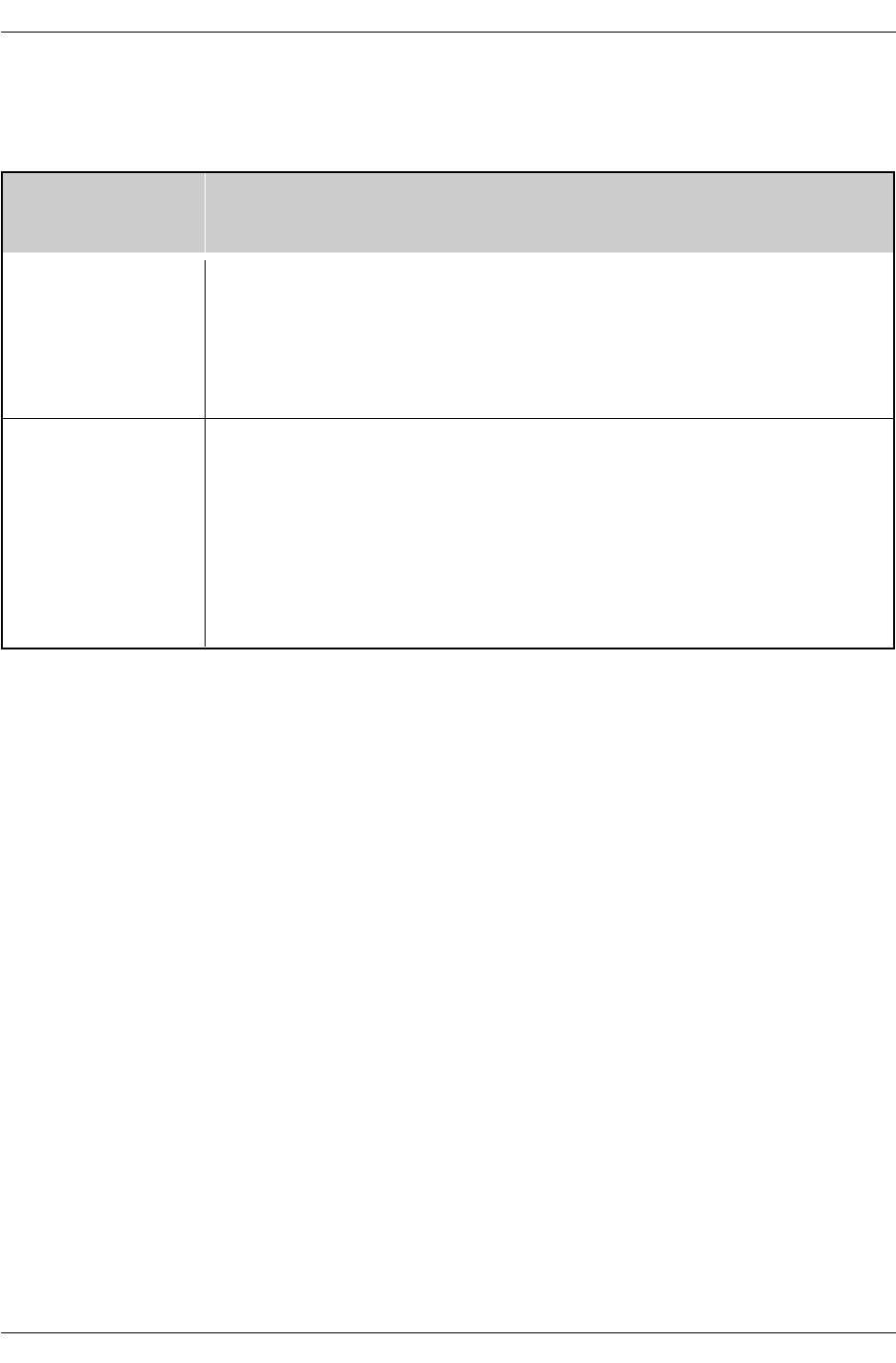
18. Tune Command (Command: m a)
GTo tune channel to following physical/major/minor number
Transmission
Data 0:
Physical Channel Number(Transmit by Hexadecimal code)
NTSC air:02~45
NTSC cable: 01, 0E~7D
ATSC air:01~45
ATSC cable:01~87
Data 1,Data 2:
Major Channel Number (two part)/ Channel Number (One part)
Data1: High byte
Data2: Low byte
Two part channel number: Major number-Minor number
One part channel number: If the channel band is ATSC
digital cable, it can be used. In case of using one part chan
nel number, minor channel does not need.
Data 3, Data 4:
Minor Channel Number(Data 3: High byte)(Data 4: Low byte)
Data 5:
[m][a][ ][Set ID][ ][Data0][ ][Data1][ ][Data2][ ][Data3][ ][Data4][ ][Data5][Cr]
7Main
Picture 6
Two/One
Part
Channel
Using
Physical
Channel
4
Reserv
ed 3210Step
0
1
Main 0
1
Two
One
Use
No Use
x
xx
x
x
x
x
x
x
x
x
x
0
1
0
0
0
0
0
0
0
1
1
1
1
0
0
0
0
1
1
0
0
1
0
1
0
1
1
1
0
1
1
0
x
x0110
NTSC Air
ATSC
cable_auto
ATSC
Cable_irc
ATSC
Cable_hrc
ATSC
Cable_std
NTSC Cable
ATSC Air
Reserved
...
Reserved
5
0
1
Owner’s Manual
External Control Device Setup
21. Input select(Command: x b) (Main Picture Input)
GTo select input source for TV.
Transmission
[x][b][][Set ID][][Data][Cr]
[b][ ][Set ID][ ][OK/NG][Data][x]
Acknowledgement
Data Structure
DATA(Hex) INPUT
00 DTV (Antenna)
01
10
11
20
21
40
41
50
60
90
DTV (Cable)
Analog (Antenna)
Analog (Cable)
Video
Front Video
Component 1
Component 2
RGB DTV
RGB PC
HDMI/DVI
Owner’s Manual
Specification
Product Specifications
Product Specifications
•The specifications shown above may be changed without prior notice for quality improvement.
MODELS
AC100-240V ~ 50/60Hz 2.0A
190W
NTSC-M, ATSC, 64 & 256 QAM
VHF 2 ~ 13, UHF 14 ~ 69, CATV 1 ~ 135, CADTV 1 ~ 135, DTV 2 ~ 69
75 Ω
32 ~ 104°F (0 ~ 40°C)
Less than 80%
Width (mm)
Height (mm)
Depth (mm)
Weight (kg)
Resolution
Power requirement
Power Consumption
Television System
Program Coverage
External Antenna Impedance
Operating Temperature Range
Operating Humidity Range
1060.8
675.2
136.2
28.6
852 x 480 (Dot)
Z37LZ5D