LG Electronics USA 37LD450CUA LCD TV/MONITOR User Manual LD452C LD451C UA manual 1005
LG Electronics USA LCD TV/MONITOR LD452C LD451C UA manual 1005
Contents
- 1. Users Manual
- 2. User Manual-1
- 3. User Manual-2
User Manual-1
PREPARATION
PREPARATION
28
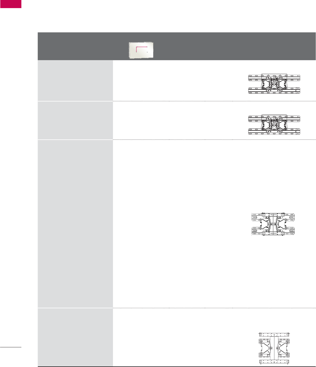
VESA WALL MOUNTING
Install your wall mount on a solid wall perpendicular to the floor. When attaching to other building mate-
rials, please contact your nearest installer.
If installed on a ceiling or slanted wall, it may fall and result in severe personal injury.
We recommend that you use an LG brand wall mount when mounting the TV to a wall.
LG recommends that wall mounting be performed by a qualified professional installer.
Model
VESA (A * B)
A
B
Standard
Screw Quantity Wall Mounting Bracket
(sold separately)
19LE5300,
22LE5300,
22LE5500,
26LE5300,
26LE5500
100 * 100 M4 4
LSW100B, LSW100BG
32LE5300,
32LD420,
32LD450,
32LD520,
32LD452C
200 * 100 M4 4
LSW100B, LSW100BG
37LE5300,
37LD450,
37LD450C,
37LD452C,
42LE5300,
42LE530C,
42LE7300,
42LD450,
42LD450C,
42LD420,
42LD520,
42LD630,
42LD451C,
42LD452C
47LE5300,
47LE530C,
47LE7300,
47LD450,
47LD450C,
47LD420,
47LD520,
47LD630,
47LD451C,
47LD452C
200 * 200 M6 4
LSW200B, LSW200BG
55LE5300,
55LE530C,
55LE7300,
55LD520,
55LD520C,
55LD630
400 * 400 M6 4
LSW400B, LSW400BG,
DSW400BG
29
PREPARATION
CAUTION
Ź Do not install your wall mount kit while your TV is turned on. It may result in personal injury due to
electric shock.
!
NOTE
Ź Screw length needed depends on the wall
mount used. For further information, refer to
the instructions included with the mount.
Ź Standard dimensions for wall mount kits are
shown in the table.
Ź When purchasing our wall mount kit, a detailed
installation manual and all parts necessary for
assembly are provided.
Ź Do not use screws longer than the standard
dimension, as they may cause damage to the
inside to the TV.
Ź For wall mounts that do not comply with the
VESA standard screw specifications, the length
of the screws may differ depending on their
specifications.
Ź Do not use screws that do not comply with the
VESA standard screw specifications.
Do not use fasten the screws too strongly, this
may damage the TV or cause the TV to a fall,
leading to personal injury. LG is not liable for
these kinds of accidents.
Ź LG is not liable for TV damage or personal
injury when a non-VESA or non specified wall
mount is used or the consumer fails to follow
the TV installation instructions.
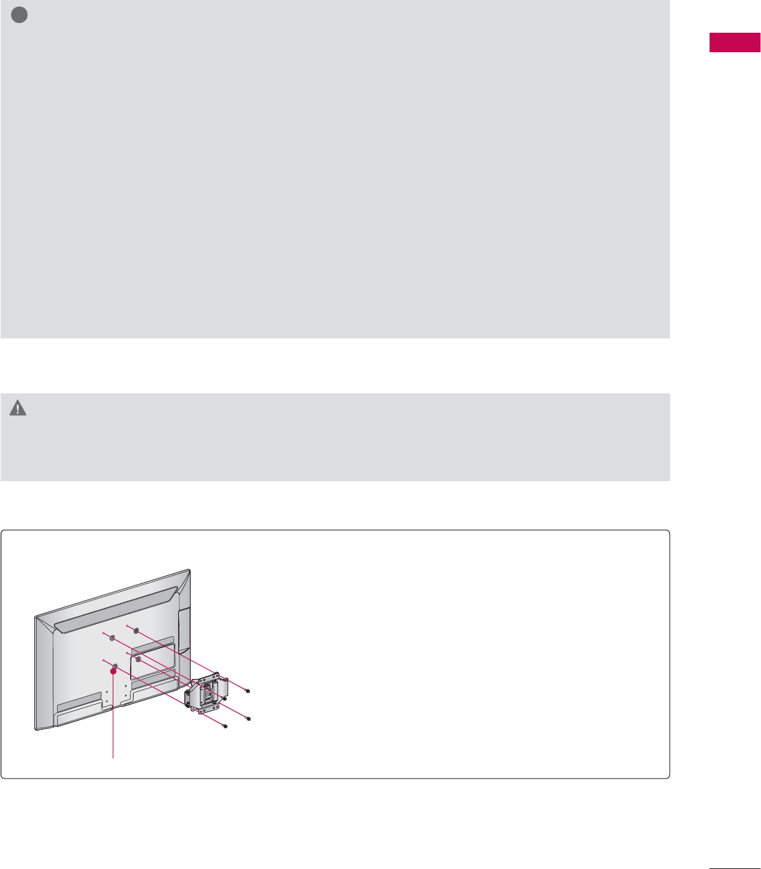
Place the ring spacers on the set before installing the wall
mounting bracket so that the inclination of the backside
of the set can be adjusted perpendicularly.
For 26LE5300, 26LE5500
4-RING SPACERS
PREPARATION
PREPARATION
30
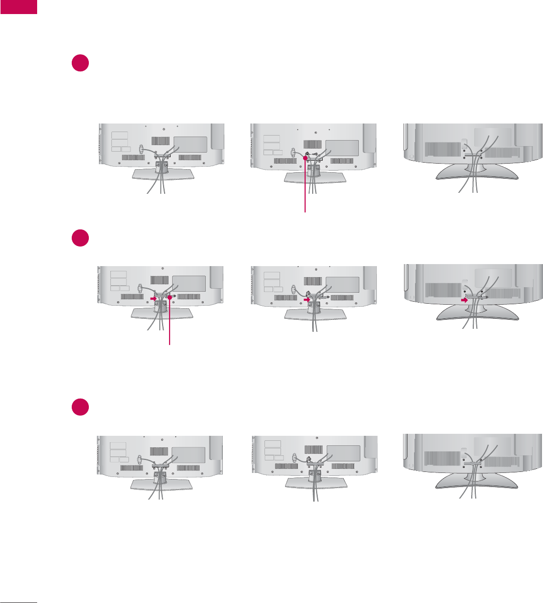
32/37/42/47LD450, 37/42/47LD450C, 32/42/47LD420, 32/42/47/55LD520, 55LD520C,
42/47/55LD630, 42/47LD451C, 32/37/42/47LD452C
CABLE MANAGEMENT
ᯫ
Image shown may differ from your TV.
Connect the cables as necessary.
To connect additional equipment, see the EXTERNAL EQUIPMENT SETUP section.
For 37/42/47LD450C, 55LD520C, 32/37/42/47LD452C: Secure the power cord with the
PROTECTIVE BRACKET/SCREW on the TV back cover. It will help prevent the power cable
from being removed by accident.
Open the CABLE MANAGEMENT CLIP as shown.
Put the cables inside the CABLE MANAGEMENT CLIP and snap it closed.
CABLE MANAGEMENT CLIP
PROTECTIVE BRACKET/SCREW
31
PREPARATION
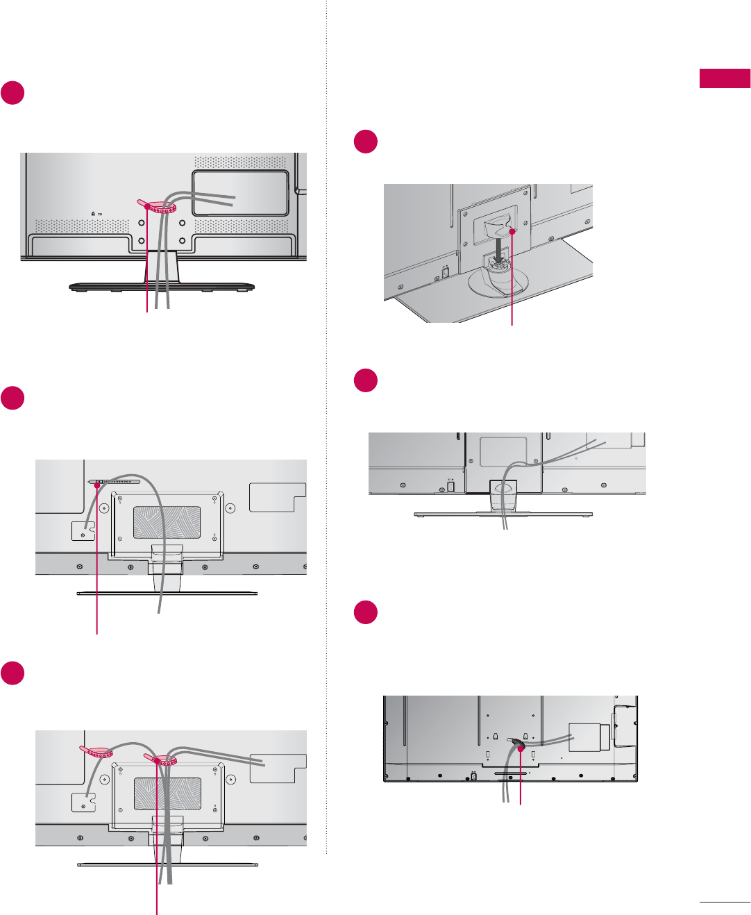
CABLE HOLDER
CABLE HOLDER
2After connecting the cables as necessary,
install the CABLE HOLDER as shown
and bundle the cables.
1Secure the power cord with the CABLE
HOLDER on the TV back cover.
It will help prevent the power cable from
being removed by accident.
32/37/42/47/55LE5300, 42/47/55LE530C
42/47/55LE7300
19/22/26LE5300, 22/26LE5500
After connecting the cables as necessary,
install the CABLE HOLDER as shown
and bundle the cables. 1 Install the CABLE MANAGEMENT CLIP
as shown.
2
Connect the cables as necessary.
To connect additional equipment, see the
EXTERNAL EQUIPMENT SETUP section.
1
Connect the cables as necessary.
To connect additional equipment, see the
EXTERNAL EQUIPMENT SETUP section.
Install CABLE HOLDER as shown and
bundle the cables.
CABLE HOLDER
FOR DESK-TYPE STAND
FOR WALL MOUNT
CABLE MANAGEMENT CLIP
CABLE HOLDER
PREPARATION
PREPARATION
32
DESKTOP PEDESTAL INSTALLATION
SWIVEL STAND
(Except
19/22LE5300, 22LE5500
)
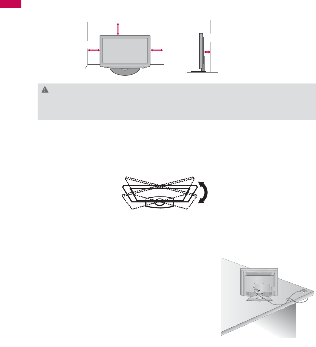
After installing the TV, you can adjust the TV set manually to the left or right direction by 20 º to suit
your viewing position.
ᯫ
Image shown may differ from your TV.
For proper ventilation, allow a clearance of 10.1 cm (4 inch) on all four sides from the wall.
10.1 cm (4 inch)
10.1 cm (4 inch)
10.1 cm (4 inch)
10.1 cm (4 inch)
CAUTION
Ź Ensure adequate ventilation by following the clearance recommendations.
Ź Do not mount near or above any type of heat source.
KENSINGTON SECURITY SYSTEM
ᯫ
This feature is not available for all models.
- The TV is equipped with a Kensington Security System con-
nector on the back panel. Connect the Kensington Security
System cable as shown below.
- For the detailed installation and use of the Kensington Security
System, refer to the user’s guide provided with the Kensington
Security System.
For further information, contact http://www.kensington.com,
the internet homepage of the Kensington company. Kensington
sells security systems for expensive electronic equipment such
as notebook PCs and LCD projectors.
NOTE: The Kensington Security System is an optional accessory.
33
PREPARATION
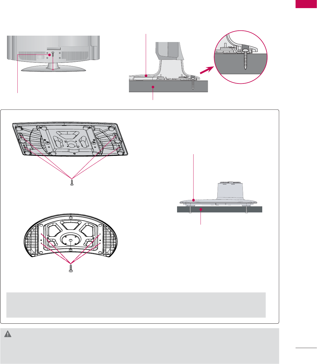
ATTACHING THE TV TO A DESK
(For 32/42LD420, 32/37/42LD450, 37/42LD450C, 32/42LD520, 42LD630, 32LE5300,
42LD451C, 32/37/42LD452C)
The TV must be attached to a desk so it cannot be pulled in a forward/backward direction, poten-
tially causing injury or damaging the product.
ᯫ
Image shown may differ from your TV.
1-Screw
( provided as parts of the product)
Desk
Stand
WARNING
Ź To prevent TV from falling over, the TV should be securely attached to the floor/wall per installa-
tion instructions. Tipping, shaking, or rocking the machine may cause injury.
4-Screws
(not provided as parts of the product)
Desk
Stand
For 37/42/47LD450C, 32/37/42/47LD452C
Ź Recommended screw size: M5 x L (*L: Table depth + 8~10 mm)
ex) Table depth: 15mm, Screw: M5 x 25
For 55LD520C
4-Screws
(not provided as parts of the product)
PREPARATION
PREPARATION
34
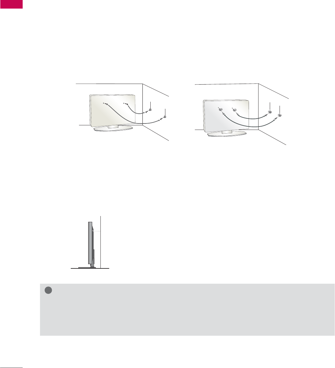
SECURING THE TV TO THE WALL TO PREVENT FALLING
WHEN THE TV IS USED ON A STAND
We recommend that you set up the TV close to a wall so it cannot fall over if pushed backwards.
Additionally, we recommend that the TV be attached to a wall so it cannot be pulled in a forward
direction, potentially causing injury or damaging the product.
Caution: Please make sure that children don’t climb on or hang from the TV.
ᯫ
Insert the eye-bolts (or TV brackets and bolts) to tighten the product to the wall as shown in the
picture.
* If your product has the bolts in the eye-bolts position before inserting the eye-bolts, loosen the
bolts.
* Insert the eye-bolts or TV brackets/bolts and tighten them securely in the upper holes.
Secure the wall brackets with the bolts (sold separately) to the wall. Match the height of the bracket
that is mounted on the wall to the holes in the product.
Ensure the eye-bolts or brackets are tightened securely.
ᯫ
Use a sturdy rope (sold separately) to tie the product. It is safer to tie the
rope so it becomes horizontal between the wall and the product.
ᯫ
You should purchase necessary components to prevent the TV from tipping over (when not using a
wall mount).
ᯫ
Image shown may differ from your TV.
!
NOTE
Ź Use a platform or cabinet strong enough and large enough to support the size and weight of
the TV.
Ź To use the TV safely make sure that the height of the bracket on the wall and the one on the TV are
the same.
35
PREPARATION
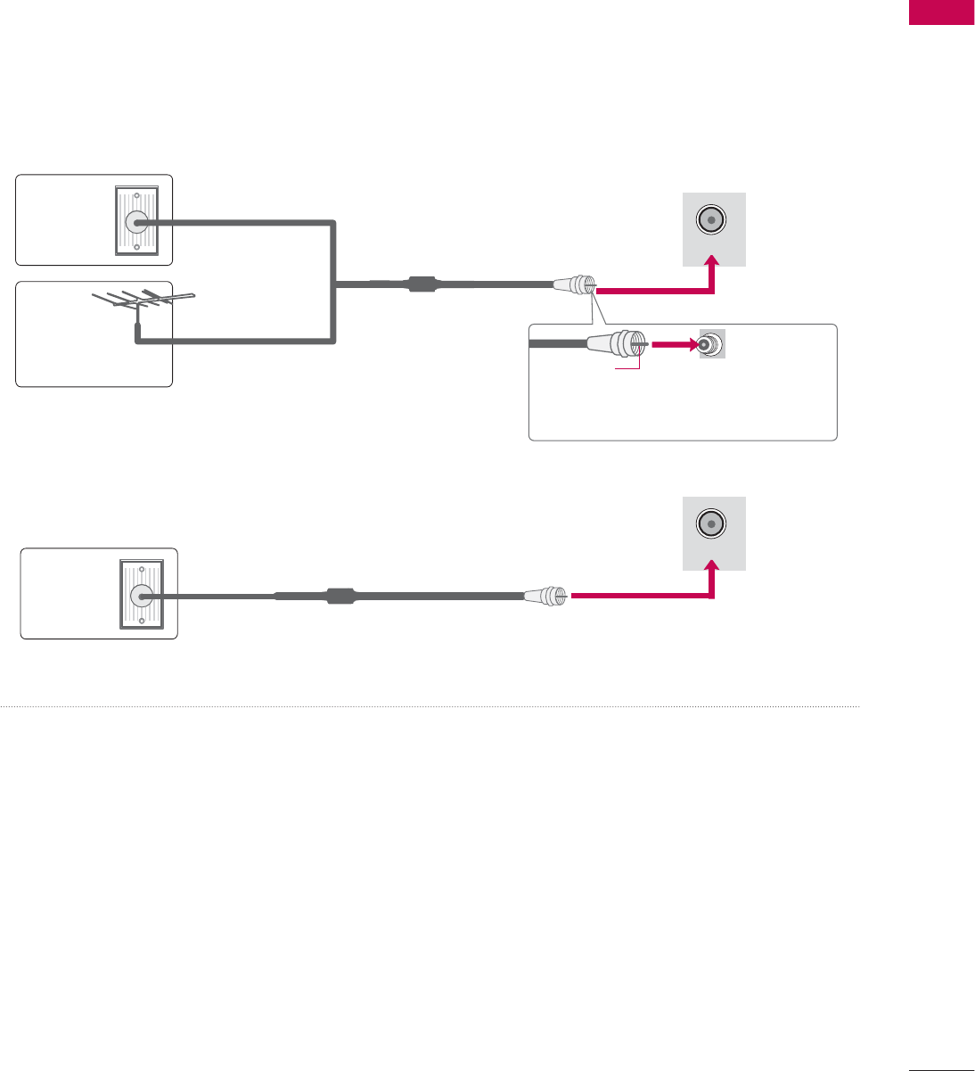
ANTENNA OR CABLE CONNECTION
ᯫ
To prevent damage do not connect to the power outlet until all connections are made between the
devices.
ᯫ
Image shown may differ from your TV.
1. Antenna (Analog or Digital)
Wall Antenna Socket or Outdoor Antenna without a Cable Box
Connections.
For optimum picture quality, adjust antenna direction if needed.
2. Cable
Wall
Antenna
Socket
Outdoor
Antenna
(VHF, UHF)
Cable TV
Wall Jack
Multi-family Dwellings/Apartments
(Connect to wall antenna socket)
RF Coaxial Wire (75 Ω)
RF Coaxial Wire (75 Ω)
Single-family Dwellings /Houses
(Connect to wall jack for outdoor antenna)
Be careful not to bend the copper wire
when connecting the antenna.
Copper Wire
ᯫ
If the antenna needs to be split for two TV’s, install a 2-Way Signal Splitter.
ᯫ
For much more information about antennas visit our Knowledgebase at http://lgknowledgebase.
com. Search for antenna.
ANTENNA/
CABLE IN
ANTENNA/
CABLE IN
EXTERNAL EQUIPMENT SETUP
EXTERNAL EQUIPMENT SETUP
36
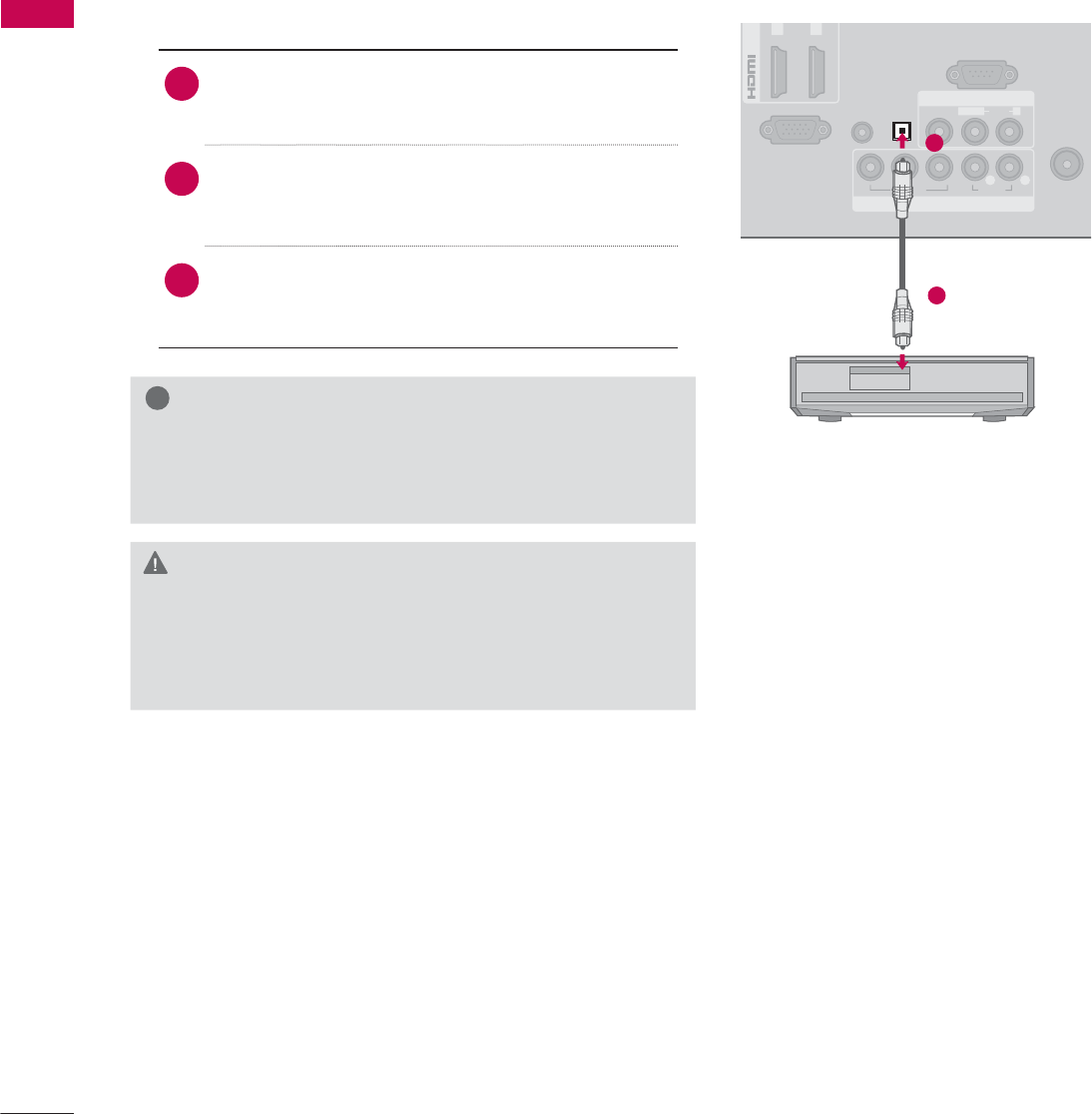
HD RECEIVER SETUP
ᯫ
To prevent the equipment damage, never plug in any power cords until you have finished connecting all
equipment.
ᯫ
I
This part of EXTERNAL EQUIPMENT SETUP mainly use picture of for 26LE5300/26LE5500.
Y, C B/PB, CR/PR
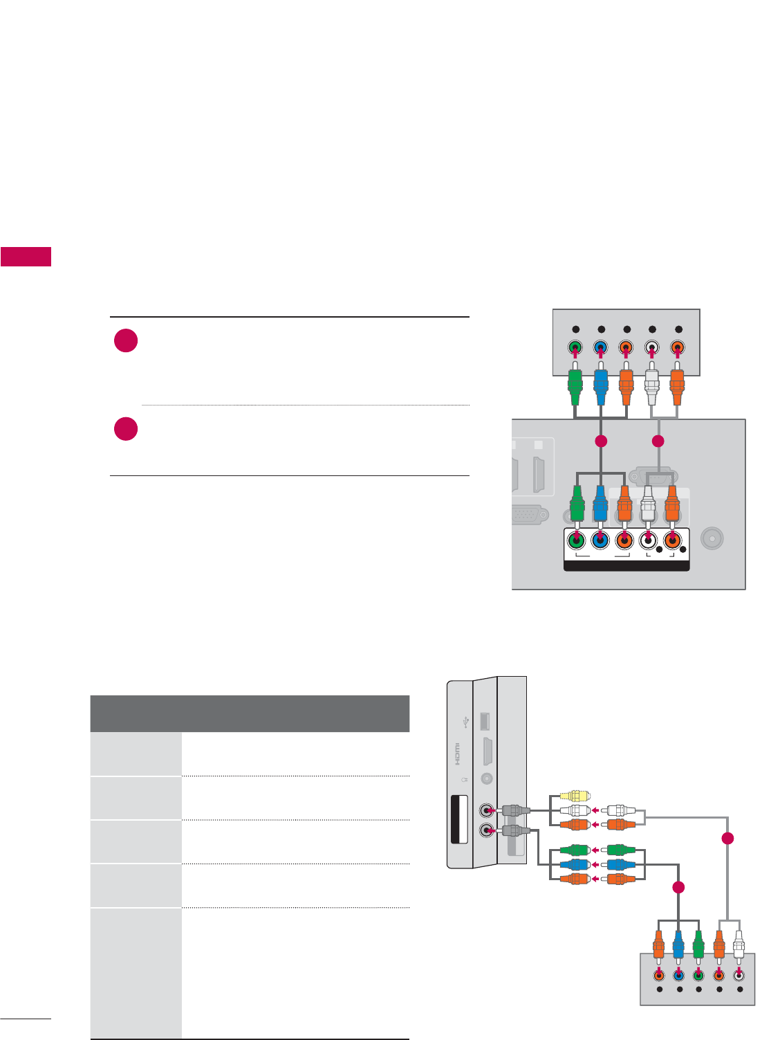
1. How to connect
1Connect the video outputs (Y, P B, PR) of the
digital set-top box to the COMPONENT IN
VIDEO or 1/2* jacks on the TV. Match the jack
colors (Y = green, PB = blue, and PR = red).
2Connect the audio output of the digital set-top
box to the COMPONENT IN AUDIO or 1/2*
jacks on the TV.
2. How to use
ᯫ
Turn on the digital set-top box.
(Refer to the owner’s manual for the digital set-
top box operation.)
ᯫ
Select the Component or Component1/2* input
source on the TV using the INPUT button on the
remote control.
Component Connection
This TV can receive digital over-the-air/digital cable signals without an external digital set-top box.
However, if you do receive digital signals from a digital set-top box or other digital external device.
Resolution Horizontal
Frequency(kHz)Vertical
Frequency(Hz)
720x480i 15.73 59.94
15.73 60.00
720x480p 31.47 59.94
31.50 60.00
1280x720p 44.96 59.94
45.00 60.00
1920x1080i
33.72 59.94
33.75 60.00
1920x1080p
26.97 23.976
27.00 24.00
33.71 29.97
33.75 30.00
67.432 59.94
67.50 60.00
EXTERNAL EQUIPMENT SETUP
ANTENNA/
CABLE IN
GB IN (PC)
AUDIO IN
RGB/DVI
VI
)
OPTICAL
DIGITAL
AUDIO OUT
AV IN
RS-232C IN
(
CONTROL&SERVICE)
1
2
VIDEO
AUDIO
L(MONO)
R
VIDEO AUDIO
YP
B
P
RL R
COMPONENT IN
Y L RP
B
P
R
1 2
* Component2: For 32/37/42/47/55LE5300,
42/47/55LE7300, 42/47/55LE530C
USB IN
IN 4
H/P
AV IN2
VIDEO / AUDIO
Y P
B
P
R
/
AUDIO
COMPONENT IN2
Y LRP
B
P
R
For 32/37/42/47/55LE5300,
42/47/55LE7300, 42/47/55LE530C
1
2
37
EXTERNAL EQUIPMENT SETUP
HDMI Connection
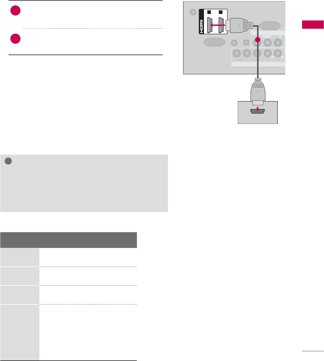
1. How to connect
1Connect the digital set-top box to HDMI/DVI IN
1, 2, 3*, or 4** jack on the TV.
2No separate audio connection is necessary.
HDMI supports both audio and video.
2. How to use
ᯫ
Turn on the digital set-top box.
(Refer to the owner’s manual for the digital set-
top box.)
ᯫ
Select the HDMI1, HDMI2, HDMI3*, or HDMI4**
input source on the TV using the INPUT
button
on the remote control.
!
NOTE
Ź If an HDMI cable doesn’t support High Speed HDMI,
it can cause flickers or no screen display. In this case
use the latest cables that support High Speed HDMI.
Ź HDMI Audio Supported Format: Dolby Digital (32 kHz, 44.1
kHz, 48 kHz), Linear PCM (32 kHz, 44.1 kHz, 48 kHz)
HDMI-DTV
Resolution Horizontal
Frequency(kHz)Vertical
Frequency(Hz)
720x480p 31.47 59.94
31.50 60.00
1280x720p 44.96 59.94
45.00 60.00
1920x1080i
33.72 59.94
33.75 60.00
1920x1080p
26.97 23.976
27.00 24.00
33.71 29.97
33.75 30.00
67.432 59.94
67.50 60.00
DC-IN
RGB IN (PC)
AUDIO IN
RGB/DVI
OPTICAL
DIGITAL
AUDIO OUT
COMPONENT IN
AV IN
RS-232C IN
(
CONTROL&SERVICE)
VIDEO
AUDIO
L(MONO)
R
VIDEO AUDIO
YP
B
P
RL R
(DVI)
/DVI IN
1 2
HDMI OUTPUT
1
* HDMI3: For 26LE5300, 26LE5500, 32/42/47/55LD520,
55LD520C, 42/47/55LD630
** HDMI4: For 32/37/42/47/55LE5300, 42/47/55LE7300,
42/47/55LE530C
EXTERNAL EQUIPMENT SETUP
EXTERNAL EQUIPMENT SETUP
38
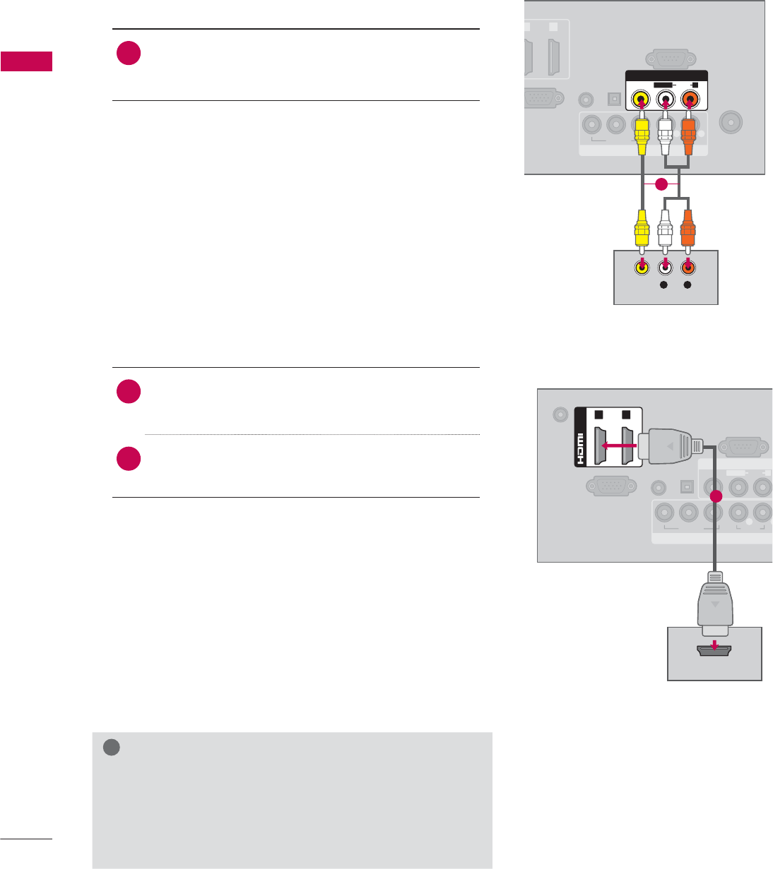
DVI to HDMI Connection
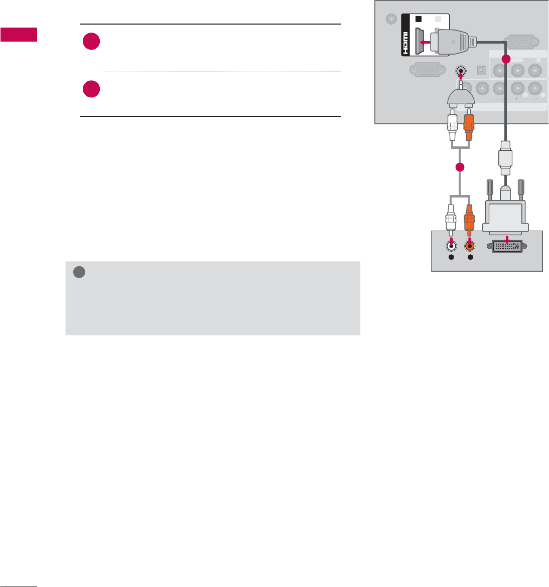
1. How to connect
1Connect the DVI output of the digital set-top
box to the HDMI/DVI IN 1 or 2* jack on the TV.
2Connect the digital set-top box audio output to
the AUDIO IN (RGB/DVI) jack on the TV.
2. How to use
ᯫ
Turn on the digital set-top box.
(Refer to the owner’s manual for the digital set-
top box.)
ᯫ
Select the HDMI1 or HDMI2* input source on the
TV using the INPUT
button on the remote control.
!
NOTE
Ź A DVI to HDMI cable or adapter is required for this con-
nection. DVI doesn't support audio, so a separate audio
connection is necessary.
DC-IN
RGB IN (PC)
AUDIO IN
RGB/DVI
OPTICAL
DIGITAL
AUDIO OUT
COMPONENT IN
AV IN
RS-232C IN
(
CONTROL&SERVICE)
VIDEO
AUDIO
L(MONO)
R
VIDEO AUDIO
YP
B
P
RL R
(DVI)
/DVI IN
12
L R DVI OUTPUT
AUDIO
1
2
* HDMI2: For 32/42/47/55LD520, 55LD520C, 42/47/55LD630
39
EXTERNAL EQUIPMENT SETUP
DVD SETUP
Component Input ports
To get better picture quality, connect a DVD
player to the component input ports as shown
below.
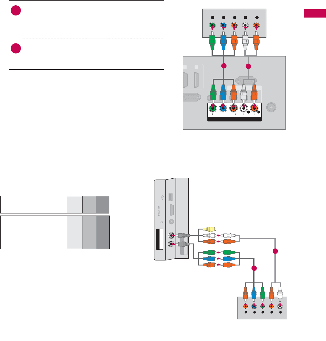
1. How to connect
1Connect the video outputs (Y, P B, PR) of the
DVD to the COMPONENT IN VIDEO or 1/2*
jacks on the TV. Match the jack colors (Y =
green, PB = blue, and PR = red).
2Connect the audio outputs of the DVD to the
COMPONENT IN AUDIO or 1/2* jacks on the
TV.
2. How to use
ᯫ
Turn on the DVD player, insert a DVD.
ᯫ
Select the Component or Component1/2* input
source on the TV using the INPUT button on the
remote control.
ᯫ
Refer to the DVD player’s manual for operating
instructions.
Component Connection
Component ports on
the TV
YPBPR
Video output ports
on DVD player
YPBPR
YB-YR-Y
YCbCr
YPbPr
ANTENNA/
CABLE IN
R
GB IN (PC)
AUDIO IN
RGB/DVI
(DVI)
OPTICAL
DIGITAL
AUDIO OUT
AV IN
RS-232C IN
(
CONTROL&SERVICE)
1 2
VIDEO
AUDIO
L(MONO)
R
VIDEO AUDIO
YP
B
P
RL R
COMPONENT IN
Y L RP
B
P
R
12
USB IN
IN 4
H/P
AV IN2
VIDEO / AUDIO
Y P
B
P
R
/
AUDIO
COMPONENT IN2
Y LRP
B
P
R
For 32/37/42/47/55LE5300,
42/47/55LE7300, 42/47/55LE530C
1
2
* Component2: For 32/37/42/47/55LE5300,
42/47/55LE7300, 42/47/55LE530C
EXTERNAL EQUIPMENT SETUP
EXTERNAL EQUIPMENT SETUP
40
Composite (RCA) Connection
1. How to connect
1Connect the AUDIO/VIDEO jacks between TV
and DVD. Match the jack colors (Video = yellow,
Audio Left = white, and Audio Right = red)
2. How to use
ᯫ
Turn on the DVD player, insert a DVD.
ᯫ
Select the AV or AV1/2* input source on the TV
using the INPUT button on the remote control.
ᯫ
Refer to the DVD player's manual for operating
instructions.
ANTENNA/
CABLE IN
GB IN (PC)
AUDIO IN
RGB/DVI
DVI
)
OPTICAL
DIGITAL
AUDIO OUT
COMPONENT IN
RS-232C IN
(
CONTROL&SERVICE)
1
2
VIDEO AUDIO
YP
B
P
RL R
AV IN
VIDEO
AUDIO
L(MONO)
R
L R
VIDEO
AUDIO
DC-IN
RGB IN (PC)
AUDIO IN
RGB/DVI
OPTICAL
DIGITAL
AUDIO OUT
COMPONENT IN
AV IN
RS-232C IN
(
CONTROL&SERVICE)
VIDEO
AUDIO
L(MONO)
R
VIDEO AUDIO
YP
B
P
RL
R
(DVI)
/DVI IN
1 2
HDMI OUTPUT
1
1
HDMI Connection
1. How to connect
1Connect the HDMI output of the DVD to the
HDMI/DVI IN 1, 2, 3*, or 4** jack on the TV.
2No separate audio connection is necessary.
HDMI supports both audio and video.
2. How to use
ᯫ
Select the HDMI1, HDMI2, HDMI3*, or HDMI4** input
source on the TV using the INPUT
button on the
remote control.
ᯫ
Refer to the DVD player's manual for operating
instructions.
!
NOTE
Ź If an HDMI cable doesn’t support High Speed HDMI,
it can cause flickers or no screen display. In this case
use the latest cables that support High Speed HDMI.
Ź HDMI Audio Supported Format: Dolby Digital (32 kHz, 44.1
kHz, 48 kHz), Linear PCM (32 kHz, 44.1 kHz, 48 kHz)
* AV2: Except 19/22/26LE5300, 22/26LE5500
* HDMI3: For 26LE5300, 26LE5500, 32/42/47/55LD520,
55LD520C, 42/47/55LD630
** HDMI4: For 32/37/42/47/55LE5300, 42/47/55LE7300,
42/47/55LE530C
41
EXTERNAL EQUIPMENT SETUP
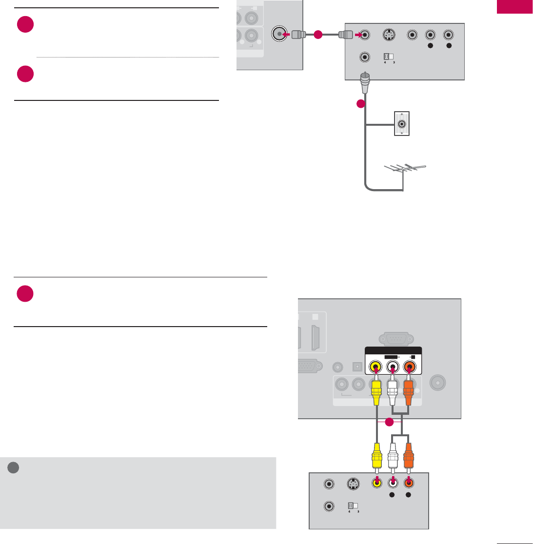
VCR SETUP
Antenna Connection
N
N
AUDIO
O
)
R
AUDIO
L R
ANTENNA/
CABLE IN
L R
S-VIDEO VIDEO
AUDIO
OUTPUT
SWITCH
ANT IN
ANT OUT
Wall Jack
Antenna
1. How to connect
1Connect the RF antenna out socket
of the VCR to the ANTENNA/CABLE
IN socket on the TV.
2Connect the antenna cable to the RF
antenna in socket of the VCR.
2. How to use
ᯫ
Set VCR output switch to 3 or 4 and
then tune TV to the same channel num-
ber.
ᯫ
Insert a video tape into the VCR and
press PLAY on the VCR (Refer to the
VCR owner’s manual).
1
2
Composite (RCA) Connection
ANTENNA/
CABLE IN
B
IN (PC)
AUDIO IN
RGB/DVI
V
I)
OPTICAL
DIGITAL
AUDIO OUT
COMPONENT IN
RS-232C IN
(
CONTROL&SERVICE)
2
VIDEO AUDIO
YP
B
P
RL R
AV IN
VIDEO
AUDIO
L(MONO)
R
S-VIDEO
OUTPUT
SWITCH
ANT IN
ANT OUT
L R
VIDEO
AUDIO
1. How to connect
1Connect the AUDIO/VIDEO jacks between TV
and VCR. Match the jack colors (Video = yellow,
Audio Left = white, and Audio Right = red)
2. How to use
ᯫ
Insert a video tape into the VCR and press PLAY
on the VCR. (Refer to the VCR owner’s manual.)
ᯫ
Select the AV or AV1/2* input source on the TV
using the INPUT button on the remote control.
!
NOTE
Ź If you have a mono VCR, connect the audio cable
from the VCR to the AUDIO L(MONO) jack of the TV.
1
* AV2: Except 19/22/26LE5300, 22/26LE5500
EXTERNAL EQUIPMENT SETUP
EXTERNAL EQUIPMENT SETUP
42
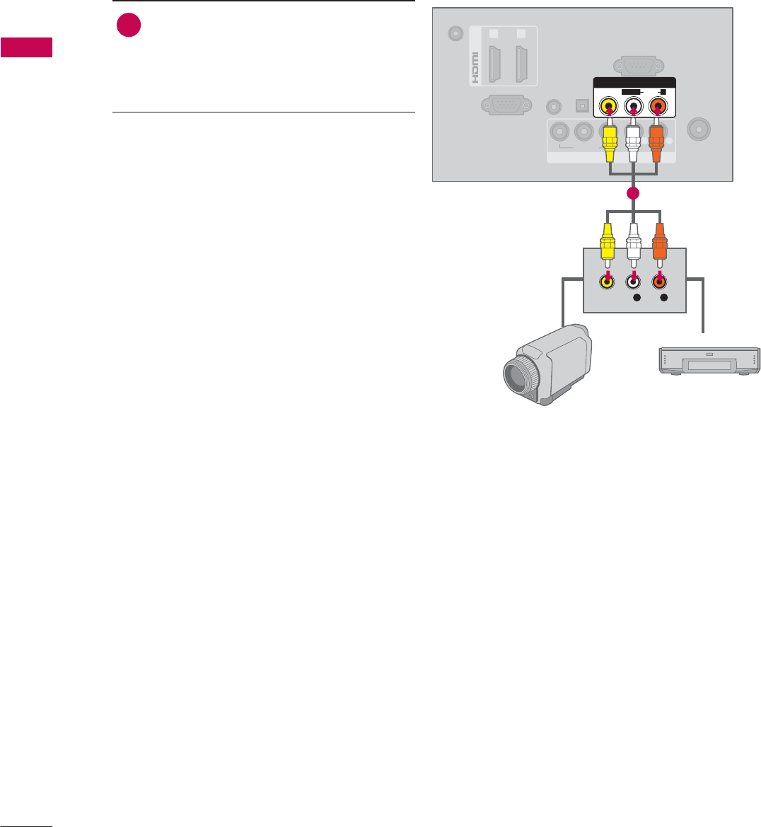
OTHER A/V SOURCE SETUP
ANTENNA/
CABLE IN
DC-IN
RGB IN (PC)
AUDIO IN
RGB/DVI
(DVI)
OPTICAL
DIGITAL
AUDIO OUT
/DVI IN
COMPONENT IN
RS-232C IN
(
CONTROL&SERVICE)
1 2
VIDEO AUDIO
YP
B
P
RL R
AV IN
VIDEO
AUDIO
L(MONO)
R
L R
VIDEO
Camcorder
Video Game Set
1. How to connect
1Connect the AUDIO/VIDEO jacks
between TV and external equipment.
Match the jack colors
.
(Video = yellow, Audio Left = white, and
Audio Right = red)
2. How to use
ᯫ
Select the AV or AV1/2* input source on
the TV using the INPUT button on the
remote control.
ᯫ
Operate the corresponding external
equipment.
1
* AV2: Except 19/22/26LE5300, 22/26LE5500
43
EXTERNAL EQUIPMENT SETUP
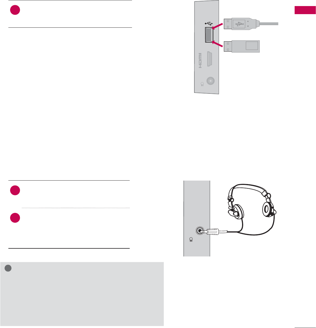
USB CONNECTION
USB IN
IN 3
H/P
Memory Key
or
1. How to connect
1 Connect the USB device to the USB
IN jack on the side of TV.
2. How to use
ᯫ
After connecting the USB IN jack, you
use the USB function. (Źp.78)
HEADPHONE SETUP
(Except 37/42/47LD450C, 32/37/42/47LD452C)
H/P
You can listen to the sound through the headphone.
1. How to connect
1Plug the headphone into the head-
phone socket.
2To adjust the headphone volume,
press the VOL +/- button. If you
press the MUTE button, the sound
from the headphone is switched off.
!
NOTE
Ź
AUDIO menu options are disabled when connecting a
headphone.
Ź
When changing AV MODE with a headphone con-
nected, the change is applied to video but not to audio.
Ź
Optical Digital Audio Out is not available when con-
necting a headphone.
EXTERNAL EQUIPMENT SETUP
EXTERNAL EQUIPMENT SETUP
44
ANTENNA/
CABLE IN
RGB IN (PC)
AUDIO IN
RGB/DVI
(DVI)
/
DVI IN
COMPONENT IN
AV IN
RS-232C IN
(
CONTROL&SERVICE)
1 2
VIDEO
AUDIO
L(MONO)
R
VIDEO AUDIO
YP
B
P
RL R
OPTICAL
DIGITAL
AUDIO OUT
AUDIO OUT CONNECTION
Send the TV’s audio to external audio equipment via the Audio Output port.
If you want to enjoy digital broadcasting through 5.1-channel speakers, connect the OPTICAL DIGITAL
AUDIO OUT terminal on the back of TV to a Home Theater (or amp).
!
NOTE
Ź When connecting with external audio equipment, such
as amplifiers or speakers, you can turn the TV speakers
off in the menu. (Źp.119)
CAUTION
Ź Do not look into the optical output port. Looking at
the laser beam may damage your vision.
Ź Audio with ACP (Audio Copy Protection) function may
block digital audio output.
1. How to connect
1Connect one end of the optical cable to the
TV port of OPTICAL DIGITAL AUDIO OUT.
2Connect the other end of the optical cable to
the digital audio input on the audio equip-
ment.
3Set the “TV Speaker option - Off” in the
AUDIO menu. (Źp.119). See the external audio
equipment instruction manual for operation.
1
2
45
EXTERNAL EQUIPMENT SETUP
DC-IN
(DVI)
OPTICAL
DIGITAL
AUDIO OUT
/D
V
COMPONENT IN
AV IN
RS 232C
IN
(
CONTROL&SERVICE)
VIDEO
AUDIO
L(MONO)
R
VIDEO AUDIO
YP
B
P
RL
RGB IN (PC)
AUDIO IN
RGB/DVI
RGB OUTPUT AUDIO
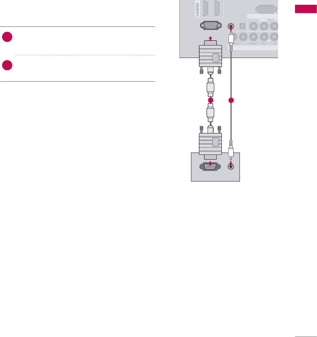
PC SETUP
This TV provides Plug and Play capability, meaning that a PC adjusts automatically to the TV’s set-
tings.
1. How to connect
1Connect the VGA output of the PC to the
RGB IN (PC) jack on the TV.
2Connect PC audio output to the AUDIO IN
(RGB/DVI) jack on the TV.
2. How to use
ᯫ
Turn on the PC and the TV.
ᯫ
Select the RGB-PC input source on the TV using
the INPUT button on the remote control.
VGA (D-Sub 15 Pin) Connection
1 2
EXTERNAL EQUIPMENT SETUP
EXTERNAL EQUIPMENT SETUP
46
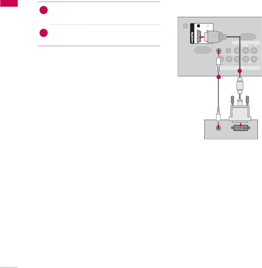
DVI to HDMI Connection
1. How to connect
1Connect the DVI output of the PC to the
HDMI/DVI IN 1 or 2* jack on the TV.
2Connect the PC audio output to the AUDIO IN
(RGB/DVI) jack on the TV.
2. How to use
ᯫ
Turn on the PC and the TV.
ᯫ
Select the HDMI1 or HDMI2* input source on the
TV using the INPUT
button on the remote control.
DC-IN
RGB IN (PC)
AUDIO IN
RGB/DVI
OPTICAL
DIGITAL
AUDIO OUT
COMPONENT IN
AV IN
RS-232C IN
(
CONTROL&SERVICE)
VIDEO
AUDIO
L(MONO)
R
VIDEO AUDIO
YP
B
P
RL R
(DVI)
/DVI IN
12
DVI OUTPUT
AUDIO
1
2
* HDMI2: For 32/42/47/55LD520, 55LD520C, 42/47/55LD630
47
EXTERNAL EQUIPMENT SETUP
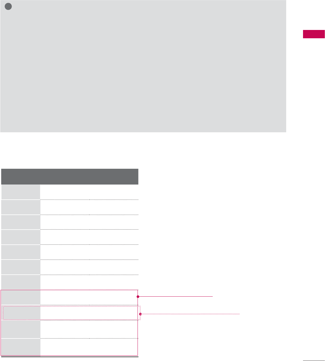
Supported Display Specifications (RGB-PC, HDMI-PC)
!
NOTE
ŹTo get the the best picture quality, adjust the PC graphics card to 1360 x 768 (19/22/26LE5300,
22/26LE5500) or 1920 x 1080 (Other models).
ŹDepending on the graphics card, DOS mode may not work if a HDMI to DVI Cable is in use.
ŹIn PC mode, there may be noise associated with the resolution, vertical pattern, contrast or bright-
ness. If noise is present, change the PC output to another resolution, change the refresh rate to
another rate or adjust the brightness and contrast on the PICTURE menu until the picture is clear.
ŹAvoid keeping a fixed image on the screen for a long period of time. The fixed image may become
permanently imprinted on the screen.
ŹThe synchronization input form for Horizontal and Vertical frequencies is separate.
ŹDepending on the graphics card, some resolution settings may not allow the image to be posi-
tioned on the screen properly.
ŹWhen selecting HDMI-PC, set the “Input Label - PC” in the OPTION menu.
Resolution Horizontal
Frequency(kHz)Vertical
Frequency(Hz)
640x350 31.468 70.09
720x400 31.469 70.08
640x480 31.469 59.94
800x600 37.879 60.31
1024x768 48.363 60.00
1280x768 47.776 59.87
1360x768
47.712 60.015
1280x1024
63.981 60.02
1600x1200
75.00 60.00
1920x1080
RGB-PC
66.587 59.934
1920x1080
HDMI-PC
67.50 60.00
Except 19/22/26LE5300,
22/26LE5500
Except 32/37/42/47/55LE5300,
42/47/55LE7300, 42/47/55LE530C
EXTERNAL EQUIPMENT SETUP
EXTERNAL EQUIPMENT SETUP
48
Screen Setup for PC mode
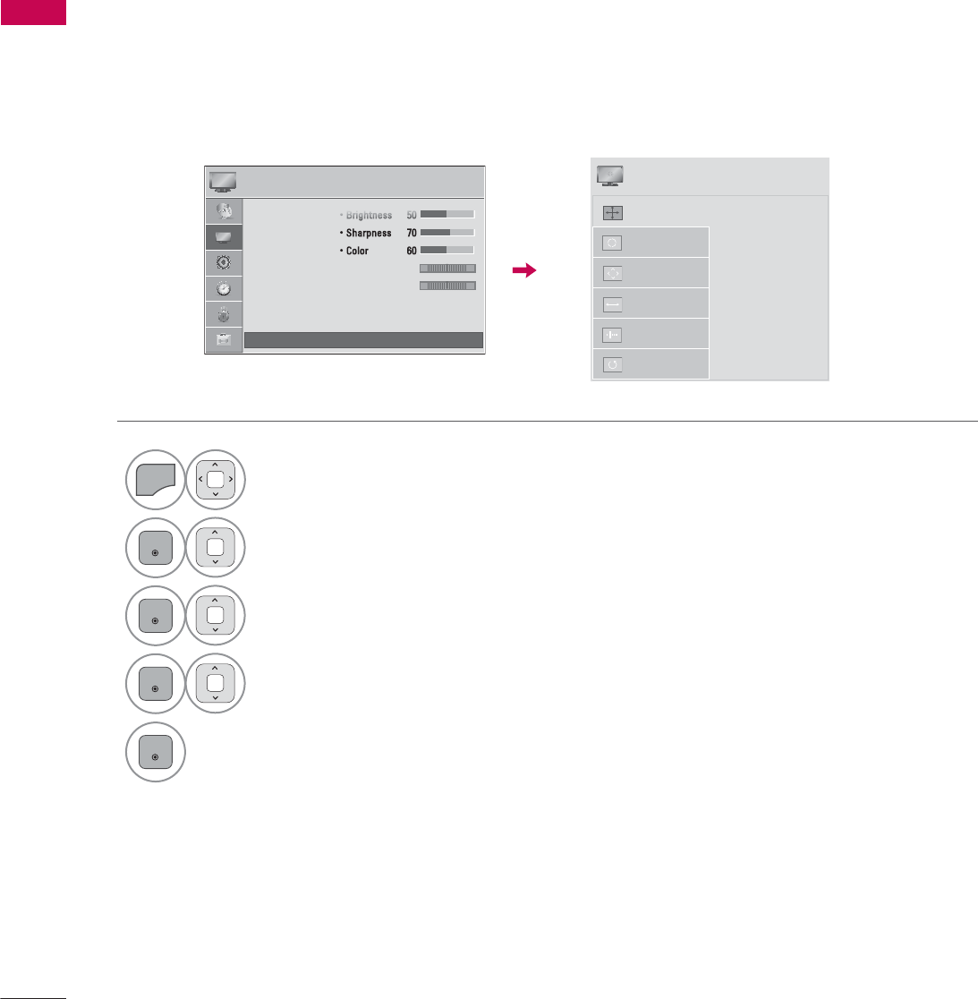
You can choose the resolution in RGB-PC mode.
The Position, Phase, and Size can also be adjusted.
You can choose this option only when the PC resolution is set to 1024X768, 1280X768 or 1360X768.
Selecting Resolution
1
MENU
Select PICTURE.
2
ENTER
Select Screen (RGB-PC).
3
ENTER
Select Resolution.
4
ENTER
Select the desired resolution.
5
ENTER
3,&785( ᯒ0RYHᯙ(QWHU
ؒ%ULJKWQHVV
ؒ6KDUSQHVV
ؒ&RORU
ؒ7LQW
ؒ&RORU7HPS
ؒ$GYDQFHG&RQWURO
ؒ3LFWXUH5HVHW
ؒ 6FUHHQ5*%3&
5*
:&
ᯙ
ᯰ
ᯡ[
۳[
۳[
$XWR&RQILJ
5HVROXWLRQ
3RVLWLRQ
6L]H
3KDVH
5HVHW
6&5((1
ᯒ0RYHᰙ3UHY
49
EXTERNAL EQUIPMENT SETUP
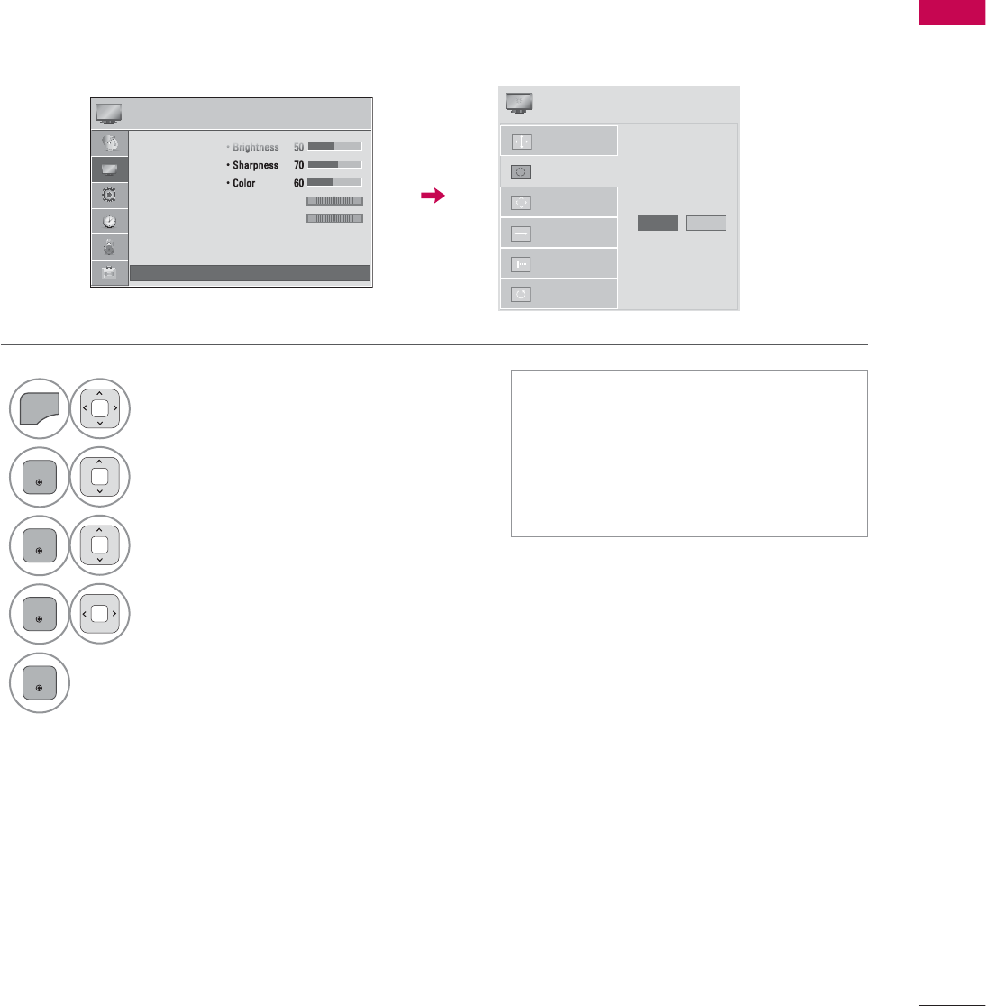
Automatically adjusts picture position and minimizes image instability. After adjustment, if the image
is still not correct, try using the manual settings or a different resolution or refresh rate on the PC.
Auto Configure
1
MENU
Select PICTURE.
2
ENTER
Select Screen (RGB-PC).
3
ENTER
Select Auto Config..
4
ENTER
Select Yes .
5
ENTER
Start Auto Configuration.
ᯫ
If the position of the image is still not
correct, try Auto adjustment again.
ᯫ
If picture needs to be adjusted again
after Auto adjustment in RGB-PC,
you can adjust the Position, Size or
Phase.
3,&785( ᯒ0RYHᯙ(QWHU
ؒ%ULJKWQHVV
ؒ6KDUSQHVV
ؒ&RORU
ؒ7LQW
ؒ&RORU7HPS
ؒ$GYDQFHG&RQWURO
ؒ3LFWXUH5HVHW
ؒ 6FUHHQ5*%3&
5*
:&
ᯙ
ᯰ
$XWR&RQILJ
5HVROXWLRQ
3RVLWLRQ
6L]H
3KDVH
5HVHW
$XWR&RQILJ
<HV 1R
6&5((1
ᯒ0RYHᰙ3UHY
EXTERNAL EQUIPMENT SETUP
EXTERNAL EQUIPMENT SETUP
50
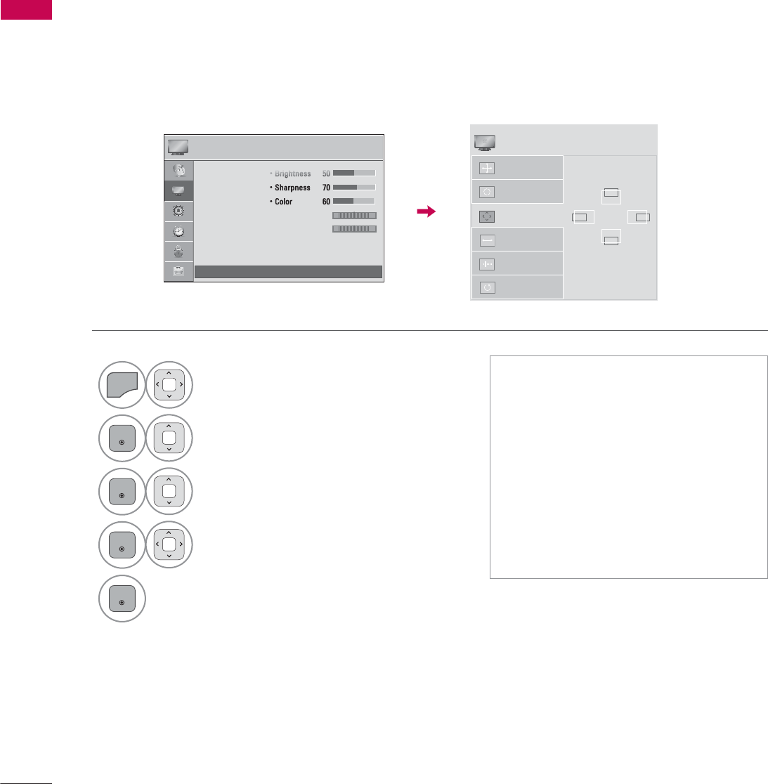
If the picture is not clear after auto adjustment or if text is shaking, adjust the picture phase manually.
This feature operates only in RGB-PC mode.
Adjustment for screen Position, Size, and Phase
1
MENU
Select PICTURE.
2
ENTER
Select Screen (RGB-PC).
3
ENTER
Select Position, Size, or Phase.
4
ENTER
Make appropriate adjustments.
5
ENTER
ᯫ
Position: This function is to adjust
picture to left/right and up/down as
you prefer.
ᯫ
Size: This function is to minimize any
vertical bars or stripes visible on the
screen background. And the horizon-
tal screen size will also change.
ᯫ
Phase: This function allows you to
remove any horizontal noise and
clear or sharpen the image of char-
acters.
3,&785( ᯒ0RYHᯙ(QWHU
ؒ%ULJKWQHVV
ؒ6KDUSQHVV
ؒ&RORU
ؒ7LQW
ؒ&RORU7HPS
ؒ$GYDQFHG&RQWURO
ؒ3LFWXUH5HVHW
ؒ 6FUHHQ5*%3&
5*
:&
ᯙ
ᯰ
$XWR&RQILJ
5HVROXWLRQ
3RVLWLRQ
6L]H
3KDVH
5HVHW
ۻ
܁۽
ۿ
6&5((1
ᯒ0RYHᰙ3UHY
51
EXTERNAL EQUIPMENT SETUP
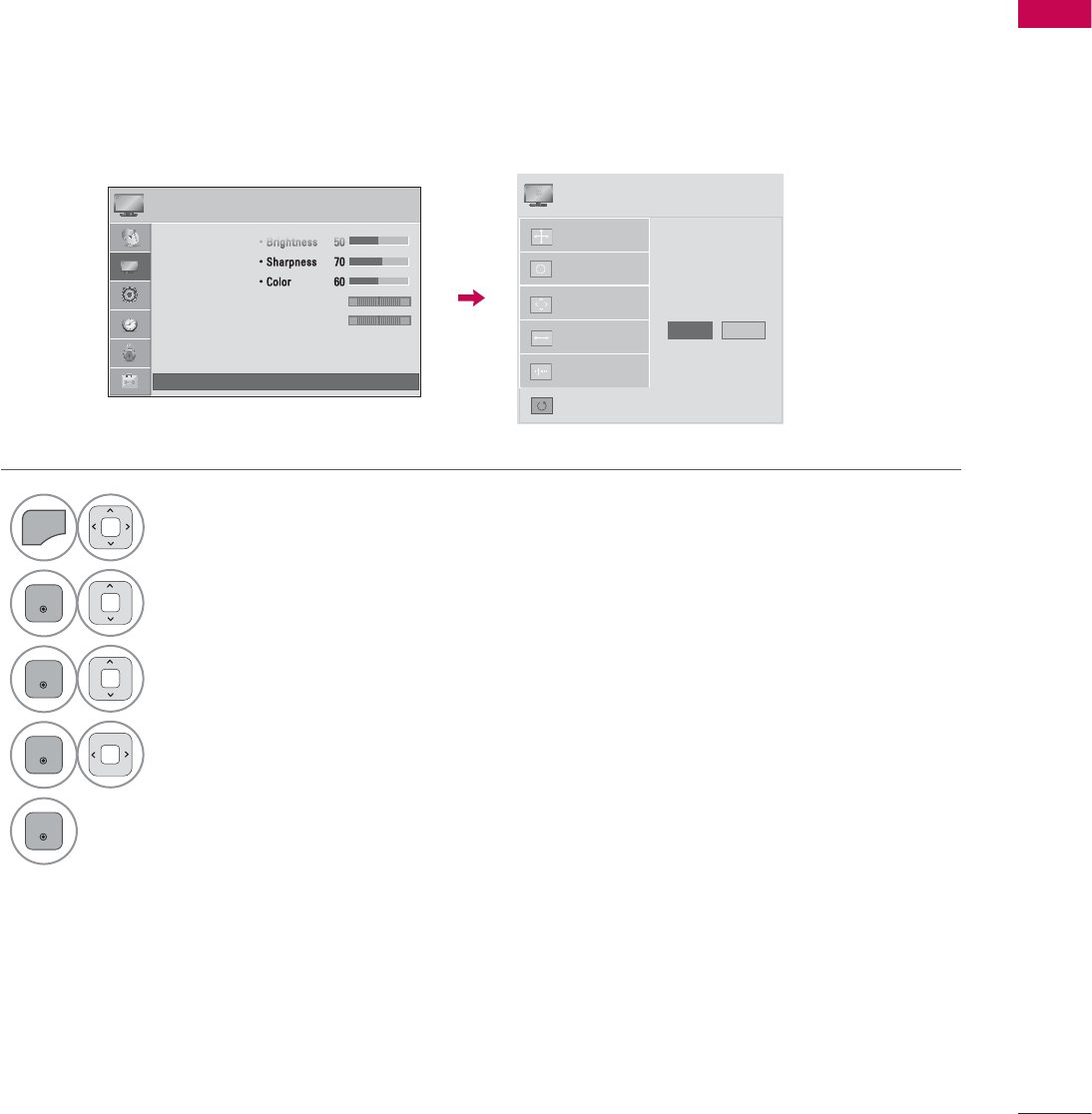
Returns Position, Size, and Phase to the default initial settings.
This feature operates only in RGB-PC mode.
Screen Reset (Reset to original initial values)
1
MENU
Select PICTURE.
2
ENTER
Select Screen (RGB-PC).
3
ENTER
Select Reset.
4
ENTER
Select Yes .
5
ENTER
Start Reset.
3,&785( ᯒ0RYHᯙ(QWHU
ؒ%ULJKWQHVV
ؒ6KDUSQHVV
ؒ&RORU
ؒ7LQW
ؒ&RORU7HPS
ؒ$GYDQFHG&RQWURO
ؒ3LFWXUH5HVHW
ؒ 6FUHHQ5*%3&
5*
:&
ᯙ
ᯰ
$XWR&RQILJ
3RVLWLRQ
5HVROXWLRQ
6L]H
3KDVH
5HVHW
7R6HW
<HV 1R
6&5((1
ᯒ0RYHᰙ3UHY
WATCHING TV / CHANNEL CONTROL
WATCHING TV / CHANNEL CONTROL
52
ENERGY
CHVOL
123
456
78
0
9
P
A
G
E
SAVING
TV
AV MODE
INPUT
FAV
RATIO
MUTE
ENTER
MARK
LIST
FLASHBK
MENU INFO
Q.MENU
BACK EXIT
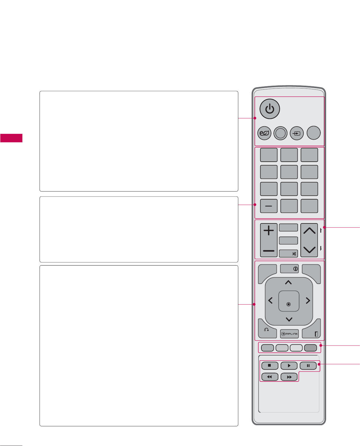
REMOTE CONTROL FUNCTIONS
When using the remote control, aim it at the remote control sensor on the TV.
The remote control may differ from the images below.
WATCHING TV / CHANNEL CONTROL
POWER Turns the TV on from standby or off to standby.
ENERGY SAVING
Adjusts the Energy Saving setting. Źp.104
AV MODE Toggles through preset Video and Audio modes.
Źp.75
INPUT Rotates through inputs.
Also switches the TV on from standby. Źp.70
TV Returns to the last TV channel.
NUMBER button
— (DASH) Used to enter a program number for multiple
program channels such as 2-1, 2-2, etc.
LIST Displays the channel table. Źp.67
FLASHBK Tunes to the last channel viewed.
MENU Displays the main menu or clears all on-screen
displays and return to TV viewing.
INFO Displays channel information at the bottom of the
screen.
Q.MENU Opens the list of Quick Menu options. Źp.59
THUMBSTICK
(Up/Down/Left
Right/ENTER)
Navigates the on-screen menus and adjusts the
system settings to your preference.
BACK Allows the user to move return one step in an
interactive application or other user interaction
function.
SIMPLINK See a list of AV devices connected to TV.
When you toggle this button, the SIMPLINK
menu appears at the screen. Źp.76
EXIT Clears all on-screen displays and return to TV
viewing.
53
WATCHING TV / CHANNEL CONTROL
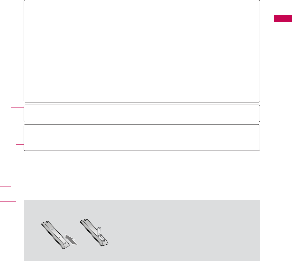
ᯫ
Open the battery compartment cover on the back
side and install the batteries matching correct polar-
ity.
ᯫ
Install two 1.5V AAA batteries. Don’t mix old or used
batteries with new ones.
ᯫ
Close cover.
Installing Batteries
VOLUME
UP/DOWN Adjusts the volume.
FAV Scroll through the programmed Favorite channels. Źp.66
MARK Select the input to apply the Picture Wizard settings. Źp.103
Use to mark or unmark a photo/music/movie. Źp.83, 88, 94
RATIO Changes the aspect ratio. Źp.100
MUTE Switches the sound on or off. Źp.54
CHANNEL
UP/DOWN
Changes the channel.
PAGE
UP/DOWN
Moves from one full set of screen information to the next one.
COLOR
BUTTON
Access special functions in some menus.
USB,
SIMPLINK
Control
buttons
• Controls MY MEDIA menu (Movie List, Photo List, Music List)
• Controls the SIMPLINK compatible devices.
WATCHING TV / CHANNEL CONTROL
WATCHING TV / CHANNEL CONTROL
54
TURNING ON THE TV
CHANNEL SELECTION
VOLUME ADJUSTMENT
Adjust the volume to suit your personal preference.
1First, connect power cord correctly.
At this moment, the TV switches to standby mode.
ᯫ
In standby mode to turn TV on, press the / I, INPUT, CH (ᰜor ᰝ) button on the TV or press
the , INPUT, CH (ᰜor ᰝ), Number (0-9) button on the remote control.
2 Select the viewing source by using the INPUT button on the remote control.
3When finished using the TV, press the POWER button on the remote control. The TV reverts
to standby mode.
!
NOTE
Ź If you intend to be away on vacation, disconnect the power plug from the wall power outlet.
Ź If you do not complete the Initial setting, it will appear whenever the TV is switched on until the
Initial setting procedure is completed.
1Press the CH (ᰜor ᰝ) or NUMBER buttons to select a channel number.
1 Press the VOL (+ or -) button to adjust the volume.
2If you want to switch the sound off, press the MUTE button.
3You can cancel the Mute function by pressing the MUTE or VOL (+ or -) button.
55
WATCHING TV / CHANNEL CONTROL
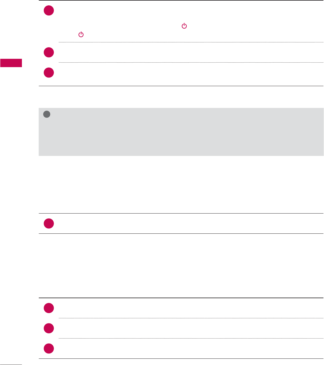
INITIAL SETTING
This Function guides the user to easily set the essential items for viewing the TV for the first time
when purchasing the TV. It will be displayed on the screen when turning the TV on for the first time. It
can also be activated from the user menus.
Step 1. Selecting Language
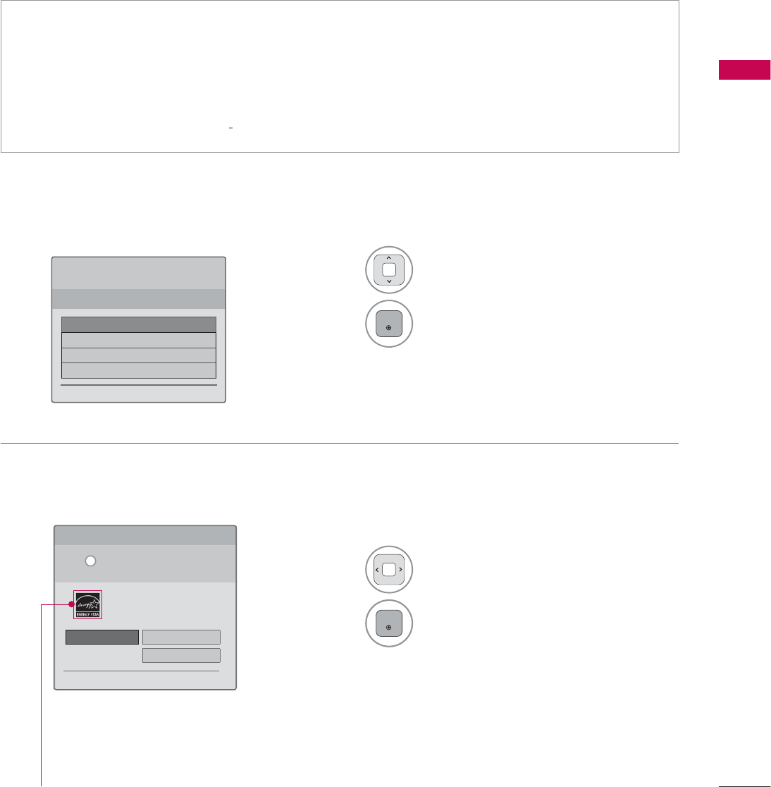
Step 2. Mode setting
ᯫ
Default selection is “Home Use”. We recommend setting the TV to “Home Use” mode for the best
picture in your home environment.
ᯫ
“Store Demo” Mode is only intended for use in retail environments. Customers can adjust the
“Picture menu - Picture mode” manually while inspecting the TV, but the TV will automatically
return to preset in-store mode after 5 minutes.
ᯫ
“Store Demo” Mode is an optimal setting for displaying at stores. “Store Demo” mode initializes
the TV to set the image quality.
1Select Menu Language.
2
ENTER
1Select Home Use.
2
ENTER
6WHS0RGH6HWWLQJ
6HOHFWLQJWKHHQYLURQPHQW
&KRRVHWKHVHWWLQJPRGH\RXZDQW
6HOHFW>+RPH8VH@ZKHQVHWWLQJ79XS
LQKRPH<RXFDQDGMXVWSLFWXUHTXDOLW\
DFFRUGLQJO\WKURXJK3LFWXUH0RGHPHQX
RSWLRQ
ᰙ3UHYLRXV ᯙ1H[W
:(/&20(
7KDQN\RXIRUFKRRVLQJ/*
ᯙ1H[W
6WHS/DQJXDJH
(QJOLVK
(VSDµRO
)UDQ«DLV
䭢⍴㮻
L
+RPH8VH 6WRUH'HPR
ؒ 'HPR0RGH 2II
For 19/22/26/32/37/42/47/55LE5300,
22/26LE5500, 42/47/55LE7300,
37/42/47LD450C, 55LD520C,
32/42/47/55LD520, 42/47/55LD630,
42/47/55LE530C, 32/37/42/47LD452C
WATCHING TV / CHANNEL CONTROL
WATCHING TV / CHANNEL CONTROL
56
Step 4. Time Zone
Step 5. Auto Tuning
1Select Time Zone option.
2Select Daylight Saving
option.
3
ENTER
1
ENTER
Check your antenna connection and
start Auto Tuning.
6WHS7LPH=RQH
ᰙ3UHYLRXV ᯙ1H[W
7LPH=RQH ܁(DVWHUQ۽
'D\OLJKW6DYLQJ $XWR
6WHS$XWR7XQLQJ
ᰙ3UHYLRXV ᯙ1H[W
%HIRUHVWDUWLQJ
EHVXUHWKDWWKH
79DQWHQQDLVFRQQHFWHG
Step 3. Power Indicator (For LED LCD TV)
1Select On or Off.
2
ENTER
6WHS3RZHU,QGLFDWRU
ᰙ3UHYLRXV ᯙ1H[W
6WDQGE\/LJKW ܁2II۽
ᯫ
This function is disable in “Step2. Mode
Setting - Store Demo”.
57
WATCHING TV / CHANNEL CONTROL
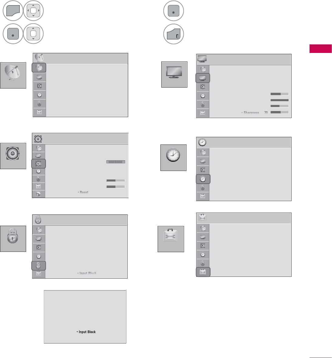
ON-SCREEN MENUS SELECTION
Your TV's OSD (On Screen Display) may differ slightly from that shown in this manual.
1
MENU
Display each menu.
2
ENTER
Select a menu item.
3
ENTER
Accept the current selection.
4
EXIT
Return to TV viewing.
&+$11(/
237,21
3,&785(
$8',2 7,0(
/2&.
3,&785( ᯒ0RYHᯙ(QWHU
ؒ $VSHFW5DWLR
ؒ 3LFWXUH:L]DUG
ؒ ᰚ(QHUJ\6DYLQJ 2II
ؒ 3LFWXUH0RGH 6WDQGDUG
ؒ%DFNOLJKW
ؒ&RQWUDVW
ؒ%ULJKWQHVV
ؒ6KDUSQHVV
7,0( ᯒ0RYHᯙ(QWHU
ؒ &ORFN
ؒ 2II7LPH 2II
ؒ 2Q7,PH 2II
ؒ 6OHHS7LPHU 2II
/2&. ᯒ0RYHᯙ(QWHU
ؒ 6HW3DVVZRUG
ؒ /RFN6\VWHP 2Q
ؒ%ORFN&KDQQHO
ؒ0RYLH5DWLQJ
ؒ795DWLQJ&KLOGUHQ
ؒ795DWLQJ*HQHUDO
ؒ'RZQORDGDEOH5DWLQJ
ؒ ,QSXW%ORFN
237,21 ᯒ0RYHᯙ(QWHU
ؒ /DQJXDJH
ؒ &DSWLRQ 2II
ؒ 3RZHU,QGLFDWRU
ؒ ,QLWLDO6HWWLQJ
ؒ 6HW,'
ؒ 0RGH6HWWLQJ +RPH8VH
$8',2 ᯒ0RYHᯙ(QWHU
ؒ $XWR9ROXPH 2II
ؒ &OHDU9RLFH,, 2IIᰕ
ؒ %DODQFH
ؒ 6RXQG0RGH 6WDQGDUG
ؒ
,QILQLWH6RXQG2II
ؒ7UHEOH
ؒ%DVV
ؒ5HVHW
/5
&+$11(/ ᯒ0RYHᯙ(QWHU
ؒ $XWR7XQLQJ
ؒ 0DQXDO7XQLQJ
ؒ &KDQQHO(GLW
ؒ 6HW3DVVZRUG
ؒ /RFN6\VWHP 2Q
ؒ%ORFN&KDQQHO
ؒ795DWLQJ(QJOLVK
ؒ795DWLQJ)UHQFK
ؒ'RZQORDGDEOH5DWLQJ
ؒ,QSXW%ORFN
ؒ .H\/RFN 2II
For USA
For Canada
WATCHING TV / CHANNEL CONTROL
WATCHING TV / CHANNEL CONTROL
58
,1387
0<0(',$
,QSXW/LVW ᯒ0RYH ᯙ(QWHU
79 86% $9 &RPSRQHQW 5*%3& +'0,
+'0, +'0,
0RYLH/LVW
0<0(',$
ᯕ,QSXW/DEHO ᰙ([LW
3KRWR/LVW 0XVLF/LVW
i.e)
Except 32/42/47LD420,
32/37/42/47LD450,
37/42/47LD450C,
32/42/47/55LD520,
55LD520C,
42/47/55LE530C,
42/47LD451C,
32/37/42/47LD452C
([WUD&RQWHQWV
For 32/37/42/47LD452C
59
WATCHING TV / CHANNEL CONTROL
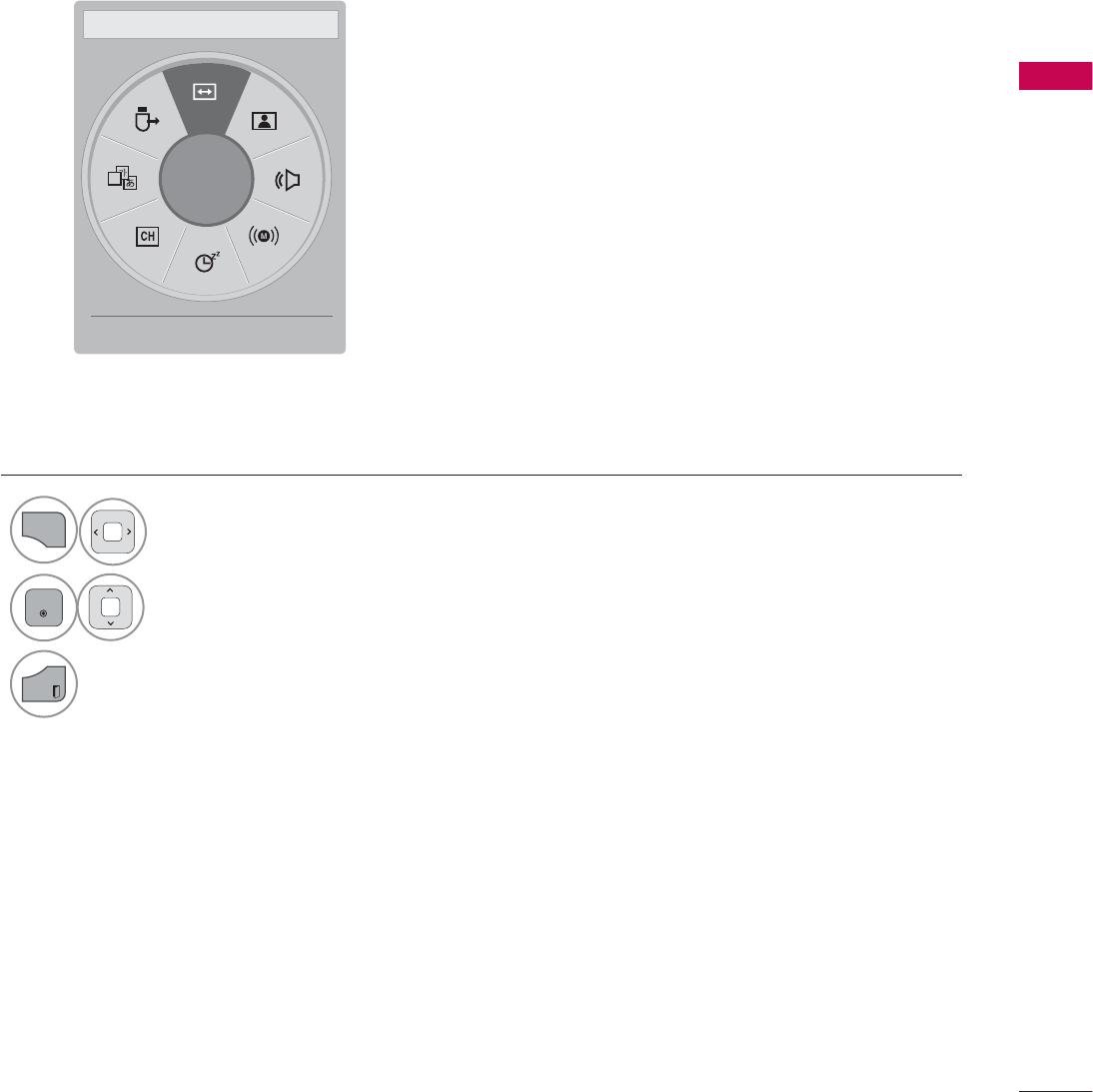
$
ᯙ
܁$VSHFW5DWLR۽ ᯳Aspect Ratio: Selects your desired picture format.
ᰗPicture Mode: Selects the desired preset picture setting.
ᰘ Sound Mode: Selects the desired preset sound setting.
ᰄMulti Audio: Changes the audio language (Digital signal).
ᰄSAP: Selects MTS sound (Analog signal).
Sleep Timer: Select the amount of time before your TV
turns off automatically.
ᰃ Del/Add: Select channel you want to add or delete.
ᰔCaption: Select on or off.
᯲USB Device: Select “Eject” in order to eject a USB device.
QUICK MENU
Your TV's OSD (On Screen Display) may differ slightly from what is shown in this manual.
Q.Menu (Quick Menu) is a menu of features which users might use frequently.
1
Q.MENU
Display each menu.
2
ENTER
Make appropriate adjustments.
3
EXIT
Return to TV viewing.
ᰙ([LW
WATCHING TV / CHANNEL CONTROL
WATCHING TV / CHANNEL CONTROL
60
CUSTOMER SUPPORT
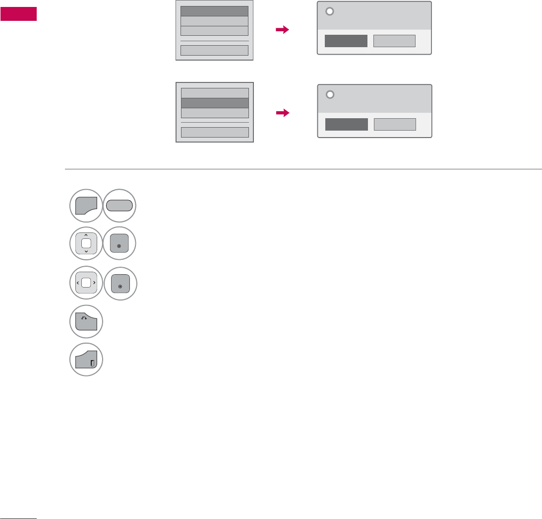
Picture Test / Sound Test
This function is a customer support function that can execute picture and sound tests.
۳3LFWXUH7HVW
ᯡ6RXQG7HVW
۳3URGXFW6HUYLFH,QIR
&ORVH
1R
<HV
'R\RXKDYHDVRXQGSUREOHPLQWKLV
VFUHHQ"
"
1
MENU
Select Customer Support.
2
ENTER
Select Picture Test or Sound Test.
3
ENTER
Select Yes .
4
BACK
Return to the previous menu.
EXIT
Return to TV viewing.
ᯡ3LFWXUH7HVW
۳6RXQG7HVW
۳3URGXFW6HUYLFH,QIR
&ORVH
1R
<HV
'R\RXKDYHDSUREOHPLQWKLVWHVW
VFUHHQ"
"
5('
61
WATCHING TV / CHANNEL CONTROL
Product/Service Info.
۳3LFWXUH7HVW
۳6RXQG7HVW
ᯡ3URGXFW6HUYLFH,QIR
&ORVH
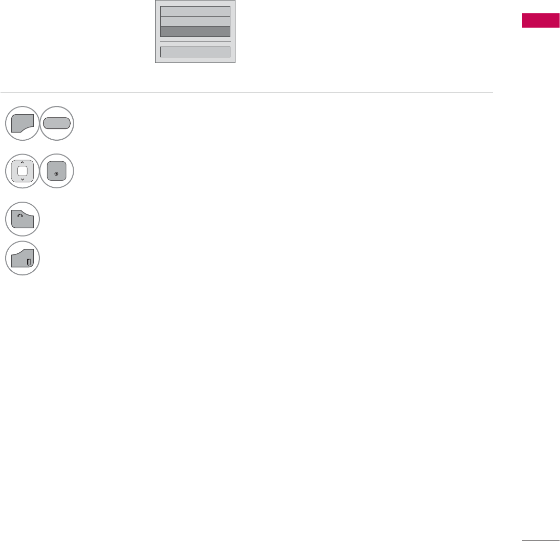
This function shows support and product information.
Customer Service Center can differ by country.
1
MENU
Select Customer Support.
2
ENTER
Select Product/Service Info..
You can check the various
product/Service infomation
based on your model.
3
BACK
Return to the previous menu.
EXIT
Return to TV viewing.
5('

WATCHING TV / CHANNEL CONTROL
WATCHING TV / CHANNEL CONTROL
62
SIMPLE MANUAL
You can easily and effectively access the TV information by viewing a simple manual on the TV.
During the Simple Manual operation, audio will be muted.
1
MENU
Select Simple Manual.
2Select the part of the manual you would like to see.
Go to the Index page.
Play the Simple Manual automatically or manually.
3
EXIT
Return to TV viewing.
5('
%/8(
*5((1
63
WATCHING TV / CHANNEL CONTROL
CHANNEL SETUP
Auto Scan (Auto Tuning)
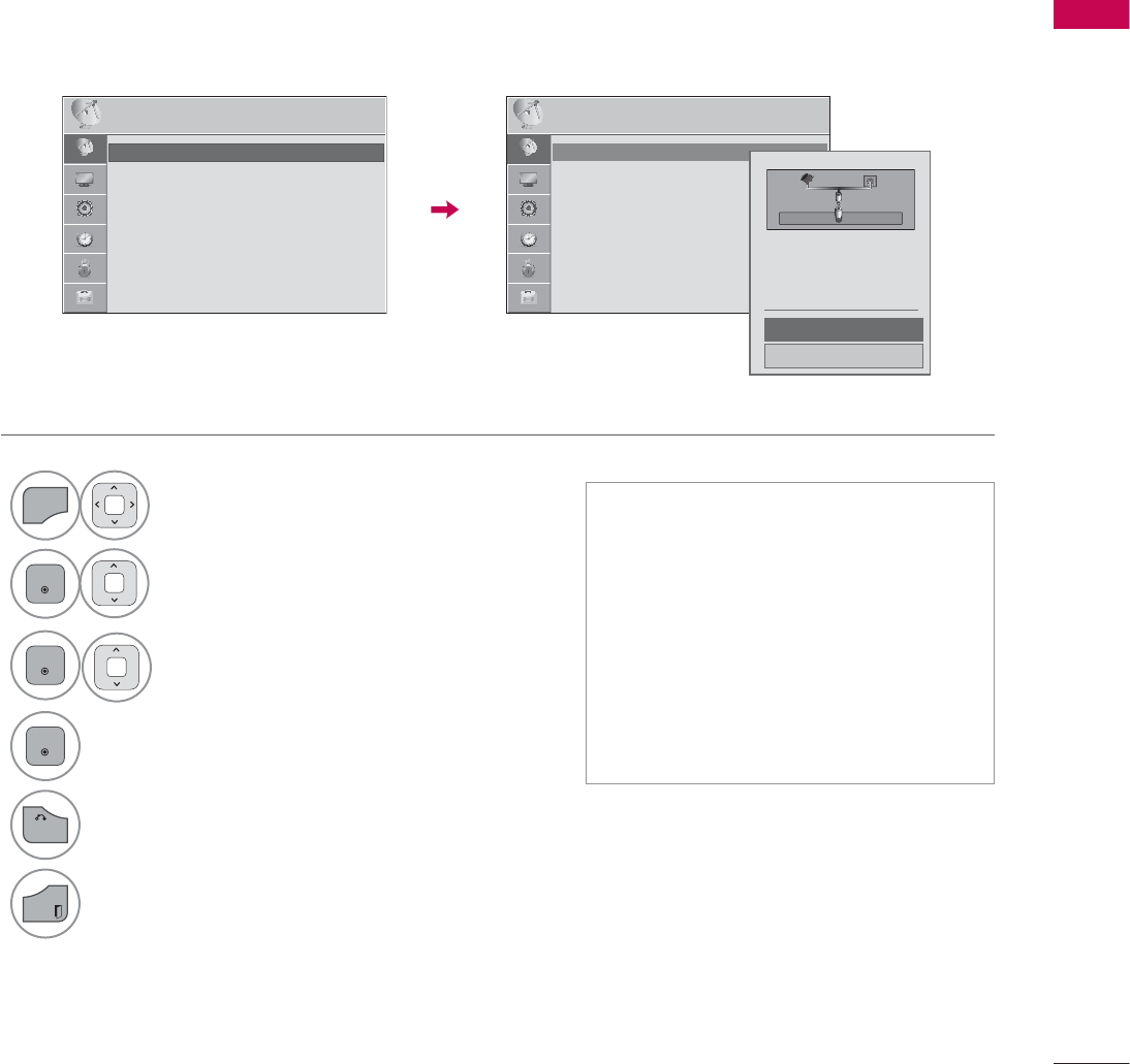
Automatically finds all channels available through antenna or cable inputs, and stores them in memory
on the channel list.
Run this function if you change your residence or move the TV.
Auto Tuning memorizes only the channels available at the time.
1
MENU
Select CHANNEL.
2
ENTER
Select Auto Tuning.
3
ENTER
Select Start.
4
ENTER
Run Auto tuning.
5
BACK
Return to the previous menu.
EXIT
Return to TV viewing.
ᯫ
The TV will ask for a password if
parental control has been activated
(LOCK Menu). Use the password you
set up in the LOCK Menu to allow a
channel search.
ᯫ
The maximum number of channels
the TV can store is 1000.
ᯫ
Found channels are grouped in the
order of DTV, TV, Cable DTV and
Cable TV.
&+$11(/ &+$11(/
ᯒ0RYHᯙ(QWHU ᯒ0RYHᯙ(QWHU
ᯱ
ᯙ
ؒ $XWR7XQLQJ
ؒ 0DQXDO7XQLQJ
ؒ &KDQQHO(GLW
ؒ $XWR7XQLQJ
ؒ 0DQXDO7XQLQJ
ؒ &KDQQHO(GLW
&KHFN\RXUDQWHQQDFRQQHFWLRQ
7KHSUHYLRXVFKDQQHOLQIRUPDWLRQ
ZLOOEHXSGDWHGGXULQJ$XWR7XQLQJ
$QWHQQD
&DEOH
6WDUW
&ORVH
WATCHING TV / CHANNEL CONTROL
WATCHING TV / CHANNEL CONTROL
64
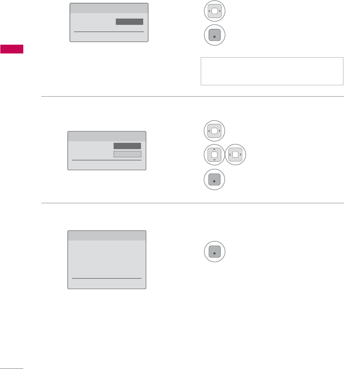
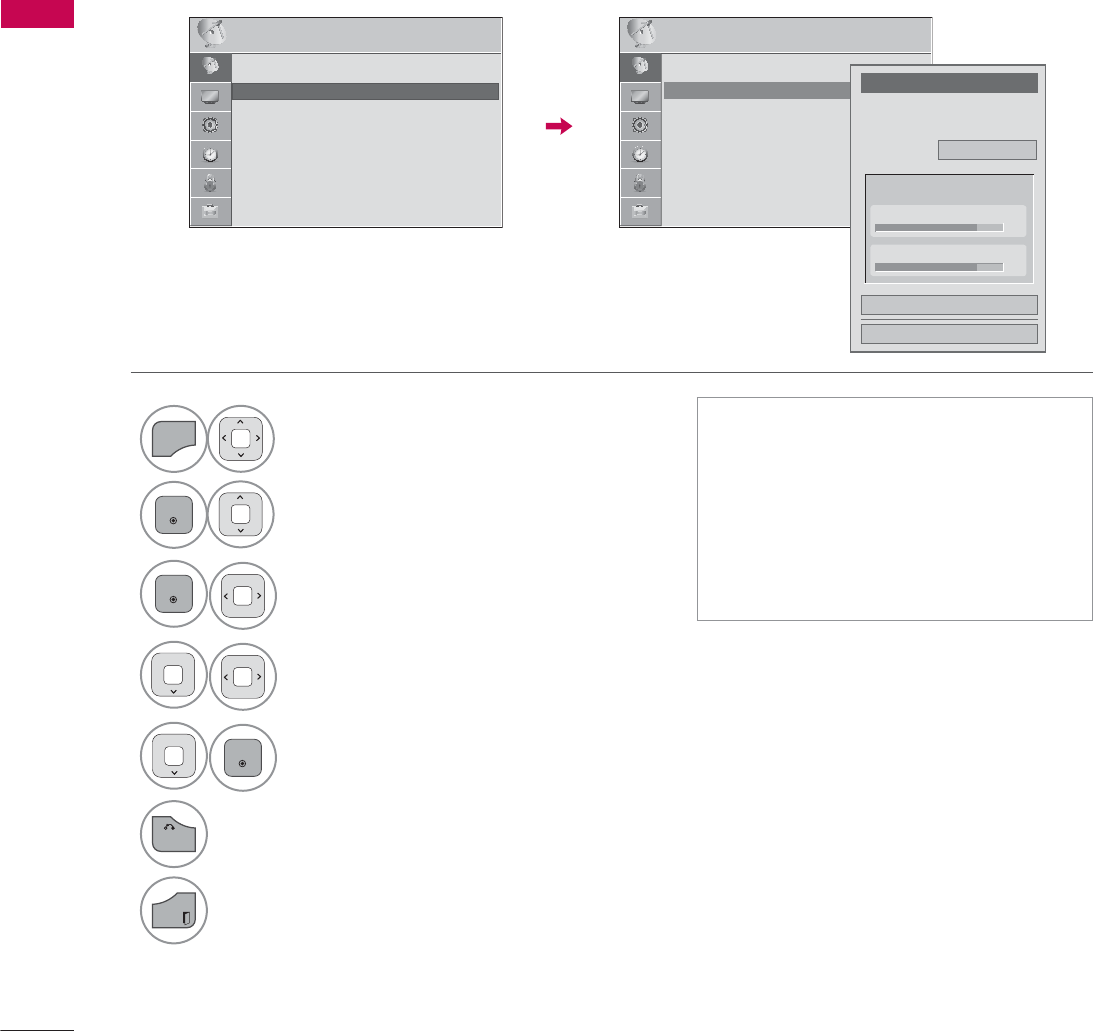
Add/Delete Channel (Manual Tuning)
When selecting DTV or Cable DTV input signal in Manual Tuning, you can view the on-screen signal
strength monitor to see the quality of the signal being received.
1
MENU
Select CHANNEL.
2
ENTER
Select Manual Tuning.
3
ENTER
Select DTV, TV, Cable DTV,
or Cable TV.
4Select channel you want to
add or delete.
5
ENTER
Select Add or Delete.
6
BACK
Return to the previous menu.
EXIT
Return to TV viewing.
ᯫ
The TV will ask for a password if
parental control has been activated
(LOCK Menu). Use the password you
set up in the LOCK Menu to allow a
channel search.
ᯫ
The maximum number of channels
the TV can store is 1000.
&+$11(/ ᯒ0RYHᯙ(QWHU
ؒ $XWR7XQLQJ
ؒ 0DQXDO7XQLQJ
ؒ &KDQQHO(GLW
&+$11(/ ᯒ0RYHᯙ(QWHU
ᯐ
ᯙ
ؒ $XWR7XQLQJ
ؒ 0DQXDO7XQLQJ
ؒ &KDQQHO(GLW
&KDQQHO
6HOHFWFKDQQHOW\SHDQG5)FKDQQHO
QXPEHU
܁
'79
۽
&ORVH
'HOHWH
'79
ؒ6LJQDO6WUHQJWK
ؒ6LJQDO4XDOLW\
65
WATCHING TV / CHANNEL CONTROL
Channel Editing
The channels in the Channel Edit List are displayed in black and the channels deleted from the Channel
Edit List are displayed in blue.
When a channel number is deleted, it means that you will be unable to select it using CHنهbutton
during TV viewing. If you wish to select the deleted channel, directly enter the channel number with the
NUMBER buttons or select it in the Channel Edit menu.
ᯫ
Keep pressing the ᰜbutton and use
the
or
!
buttons to move between
DTV, TV, Cable DTV and Cable TV.
1
MENU
Select CHANNEL.
2
ENTER
Select Channel Edit.
3
ENTER
Select a channel.
4Add or delete a channel.
Block or unblock the channel.
You can block/unblock channels even if
you select “Lock system-Off” in the LOCK
menu.
ENTER
Switch to the chosen channel number.
CH
P
A
G
E
Move the pages when the channel list is
too long.
5
BACK
Return to the previous menu.
EXIT
Return to TV viewing.
%/8(
<(//2:
5-13-1 7-1
ᯙ&+&KDQJH
'79 79 &DEOH'79 &DEOH79
ᯒ1DYLJDWLRQ ᱇3DJH&KDQJH ᯕ%ORFN8QEORFN ᯕ$GG'HOHWH
᱆)DYRULWH&K
&KDQQHO(GLW 3DJH
ᱭ)DYRULWH&K*URXS ᰙ3UHYLRXV
)DYRULWH*URXS $
&+$11(/ ᯒ0RYHᯙ(QWHU
ᯙ
ᯰ
ؒ $XWR7XQLQJ
ؒ 0DQXDO7XQLQJ
ؒ &KDQQHO(GLW
WATCHING TV / CHANNEL CONTROL
WATCHING TV / CHANNEL CONTROL
66
WATCHING TV / CHANNEL CONTROL
FAVORITE CHANNEL SETUP
Favorite Channels are a convenient feature that lets you quickly select channels of your choice without
waiting for the TV to select all the in-between channels.
1
FAV
MARK
Display the Favorite channel list.
1Select a channel.
2
ENTER
Switch to the chosen channel number.
1
CH
P
A
G
E
Turn the pages.
2
EXIT
Return to TV viewing.
Selecting a channel in the favorite
channel list
Paging through a favorite channel
list
Displaying the favorite channel list
ᯫ
You can also setup Favorite List in the
CHANNEL menu - Channel Edit.
123
45
0
6
789
1or
CH
P
A
G
E
Select your desired channel.
2
FAV
MARK
Select your desired favorite
channel group from A to D.
3Register or cancel the current channel
in favorite channel list.
Go to the “CHANNEL menu - Channel
Edit”.
4
EXIT
Return to TV viewing.
<(//2:
%/8(
FAVORITE CHANNEL LIST
ᯚᯛ)DYRULWH&K*URXS
ᯚᯛ)DYRULWH&K*URXS
)DYRULWH/LVW
)DYRULWH/LVW
ᰙ([LW
ᰙ([LW
܁*URXS$۽
܁*URXS$۽
DTV
DTV
DTV
DTV
ᯕ&K5HJ
ᯕ&K5HJ
ᯕ&K(GLW
ᯕ&K(GLW
ᯱ
ᯙ
ᯱ
ᯙ
WATCHING TV / CHANNEL CONTROL
67
CHANNEL LIST
You can check which channels are stored in the memory by displaying the channel list.
&KDQQHO/LVW ᰙ([LW
DTV
ᯢ
DTV
ᯕ&K(GLW
1Select a channel.
2
ENTER
Switch to the chosen channel number.
1
LIST
Display the Channel List.
Tune to the “CHANNEL menu - Channel
Edit”.
1
CH
P
A
G
E
Turn the pages.
2
EXIT
Return to TV viewing.
Selecting a channel in the channel list
Paging through a channel list
Displaying Channel List
%/8(
This padlock is displayed
when the channel is locked
with parental control.
ᯱ
ᯙ

WATCHING TV / CHANNEL CONTROL
WATCHING TV / CHANNEL CONTROL
68
Displaying Channel Information
CHANNEL INFORMATION
1
INFO
Show the current channel program Information
on the screen.
2Show a previous or next channel’s program infor-
mation
3
EXIT
Return to TV viewing.
0XOWLOLQJXDO᯿&DSWLRQᰇLᯢ793*'/69
%ULHI,QIR7LWOH7HVW
᯦'79&11 ᯐ&K&KDQJH۽1H[Wᯙ:DWFK
$0 $0
1RLQIRUPDWLRQ
6DUDK%UDGOH\6WHYH*UD\DQG%UHQGRQ3RQJLDSUHVHQWWKHODWHVWLQIDVKLRQWKHDUWVHQWHUWDLQPHQWOLIHVW\OHDQGFRRNLQJ
ZLWKUHJXODUDQGVSHFLDOJXHVWV
6DUDK%UDGOH\6WHYH*UD\DQG%UHQGRQ3RQJLDSUHVHQWWKHODWHVWLQIDVKLRQWKHDUWVHQWHUWDLQPHQWOLIHVW\OHDQGFRRNLQJ
ᯱ
ᯕ8S
ᯕ'RZQ
69
WATCHING TV / CHANNEL CONTROL
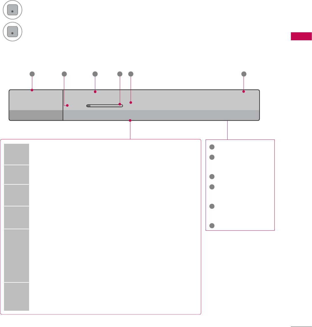
CHANNEL BRIEF INFORMATION
Brief Info shows the present screen information.
1
ENTER
Shows the current channel’s brief info screen.
2
ENTER
Return to TV viewing.
1
Program title
2
Day, Month, Year,
Present time
3
Program start time
4
Program progress
bar
5
Program finish
time
6
Banner information
6XQ)HE$0
0XOWLOLQJXDO᯿&DSWLRQᰇLᯢ793*'/69
$0 $0
%ULHI,QIR7LWOH7HVW
1H[W$01HZV
&11
᯦'79
ᱏ
6 3 11 4 5 2
Multilingual : The program contains two or more audio servic-
es. Use the Q.MENU menu to select wanted Audio.
᯿Caption : The program contains one or more caption services.
Use the Q.MENU menu to select wanted Closed caption.
Dolby Digital: The program contains a Dolby Digital audio
signal in TV and HDMI input source.
ᰆThe original aspect ratio of the video is 4:3
ᰇThe original aspect ratio of the video is 16:9 (wide)
480i
480p
720p
1080i
1080p
The video resolution is 720x480i
The video resolution is 720x480p
The video resolution is 1280x720p
The video resolution is 1920x1080i
The video resolution is 1920x1080p
ᯢ
V-Chip: The program contains V-Chip information. Refer to
the LOCK menu: A (Age), D (Dialogue), L (Language), S (Sex),
V (Violence), FV (Fantasy Violence)
WATCHING TV / CHANNEL CONTROL
WATCHING TV / CHANNEL CONTROL
70
ᯫ
When new external device is connected, this popup
menu is displayed automatically.
If selecting Ye s, you can select input source that you
want to appreciate.
ᯫ
But, when selecting “SIMPLINK - On”, popup menu for
HDMI input will not be displayed.
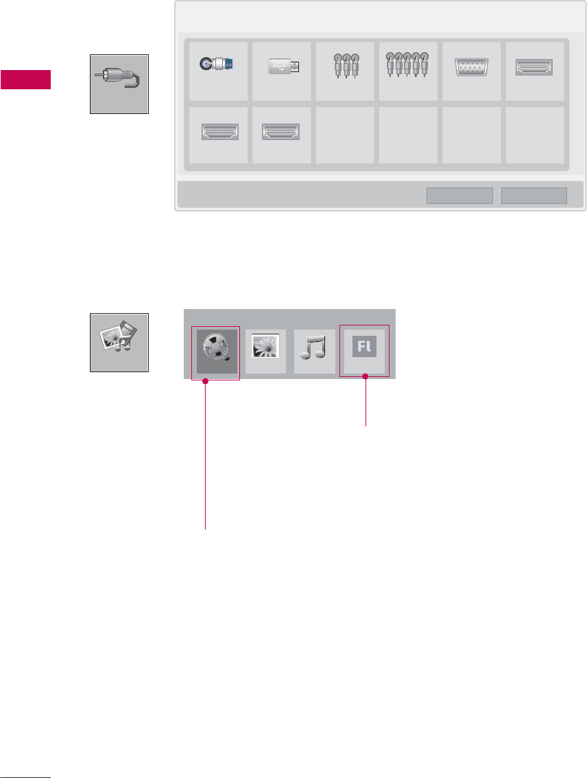
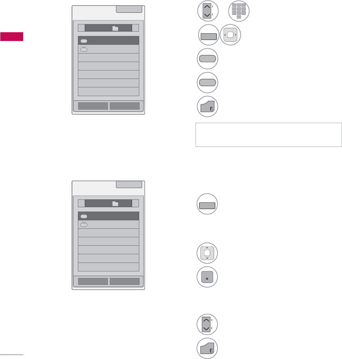
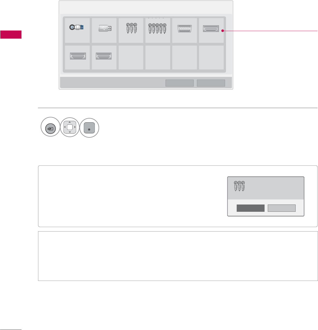
INPUT LIST
Only these input signals which are connected to a TV can be activated and selected.
1
INPUT
ENTER
Select the desired input source.
ᯫ
TV: Select it to watch over-the-air, cable and digital cable broadcasts.
ᯫ
AV: Select them to watch a VCR or other external equipment.
ᯫ
Component: Select them to watch DVD or a Digital set-top box.
ᯫ
RGB-PC: Select it to view PC input.
ᯫ
HDMI: Select them to watch high definition devices.
,QSXW/LVW ᯒ0RYH ᯙ(QWHU
79 86% $9 &RPSRQHQW 5*%3& +'0,
+'0, +'0,
ᯕ,QSXW/DEHO ᰙ([LW
Disconnected inputs are inactive
(grayed out)
1R
<HV
1HZH[WHUQDOLQSXWLVFRQQHFWHG
'R\RXZDQWWRXVHWKLV"
$9
i.e)
71
WATCHING TV / CHANNEL CONTROL
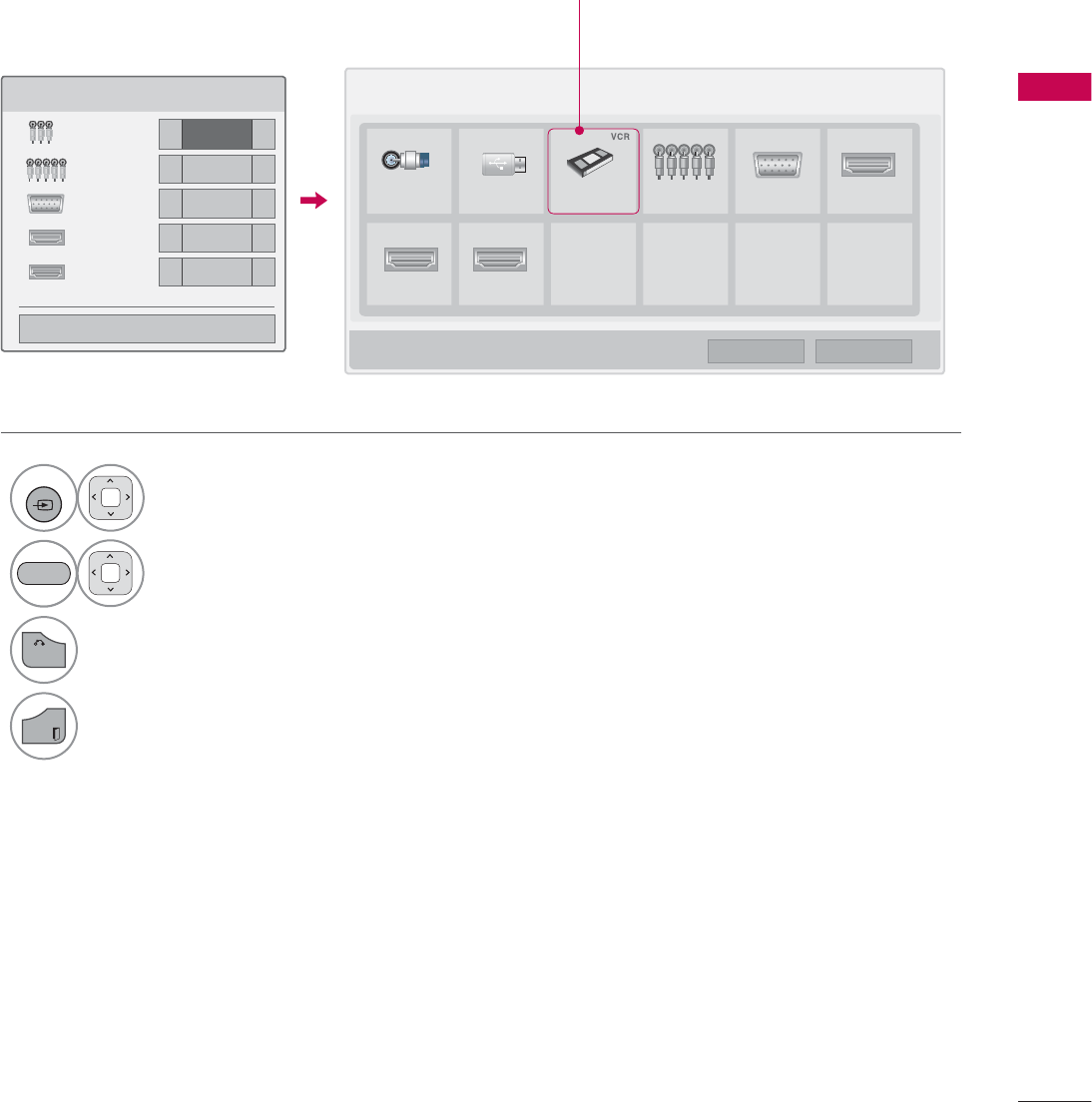
ie) Change the input label using Blue
button
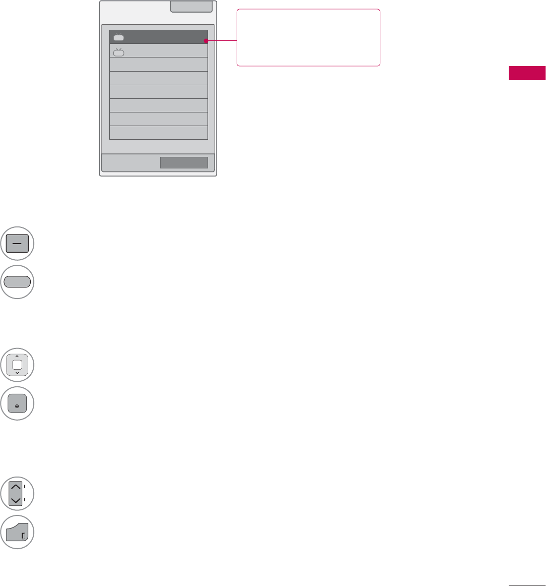
INPUT LABEL
This indicates which device is connected to which input port.
1
INPUT
Select the desired input
source.
2Select the label.
3
BACK
Return to the previous menu.
EXIT
Return to TV viewing.
,QSXW/LVW ᯒ0RYH ᯙ(QWHU
79 86% $9 &RPSRQHQW 5*%3& +'0,
+'0, +'0,
,QSXW/DEHO
$9 ܁9&5 ۽
&RPSRQHQW ܁۽
5*%3& ܁۽
+'0, ܁۽
+'0, ܁۽
ᯝ
&ORVH
ᯕ,QSXW/DEHO ᰙ([LW
%/8(
i.e) i.e)

WATCHING TV / CHANNEL CONTROL
WATCHING TV / CHANNEL CONTROL
72
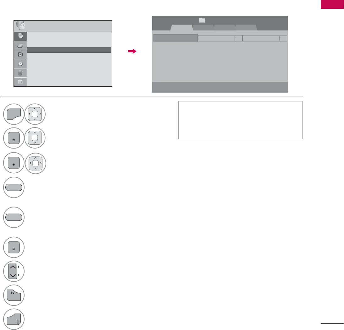
RESET TO FACTORY DEFAULT (INITIAL SETTING)
This function resets the TV to factory default and erases all stored channels.
ᯫ
When selecting “Lock System - On”
in the LOCK menu, the message to
enter the password appears.
ᯫ
If you forget your password, press
“0-3-2-5” on the remote control.
1
MENU
Select OPTION.
ENTER
Select Initial Setting.
3
ENTER
Select Yes .
4
ENTER
TV turns off automatically and starts
factory reset.
237,21 ᯒ0RYHᯙ(QWHU
ᯐ
ᯙ
ؒ /DQJXDJH
ؒ &DSWLRQ 2II
ؒ 3RZHU,QGLFDWRU
ؒ ,QLWLDO6HWWLQJ
ؒ 6HW,'
ؒ 0RGH6HWWLQJ +RPH8VH
237,21 ᯒ0RYHᯙ(QWHU
ᯐ
ᯙ
ؒ /DQJXDJH
ؒ &DSWLRQ 2II
ؒ 3RZHU,QGLFDWRU
ؒ ,QLWLDO6HWWLQJ
ؒ 6HW,'
ؒ 0RGH6HWWLQJ +RPH8VH
1R
<HV
$OOXVHUVHWWLQJVDQGFKDQQHOVHWWLQJVZLOO
EHUHVHW6WLOOFRQWLQXH"