LG Electronics USA 37LG700HUA LCD TV/MONITOR User Manual SAC30708043 Edit1
LG Electronics USA LCD TV/MONITOR SAC30708043 Edit1
Contents
- 1. User manual 1 of 2
- 2. User manual 2 of 2
User manual 1 of 2
Please read this manual carefully before operating
your set.
Retain it for future reference.
Record model number and serial number of the set.
See the label attached on the back cover and quote
this information to your dealer
when you require service.
LCD TV
OWNER’S MANUAL
32LG700H
37LG700H
42LG700H
Installer Reference for Commercial Mode
MPI/PPV Card Setup see page 19
Commercial Mode Setup see pages 87-104
P/NO : SAC30708043 (0810-REV00)
www.lgcommercial.com
This product qualifies for ENERGY STAR in the “factory default
(Home mode)” setting and this is the setting in which power
savings will be achieved.
Changing the factory default picture setting or enabling other
features will increase power consumption that could exceed the
limits necessary to quality for Energy Star rating.

1
WARNING / CAUTION
WARNING / CAUTION
To prevent fire or shock hazards, do not expose
this product to rain or moisture.
FCC NOTICE
Class B digital device
This equipment has been tested and found to comply
with the limits for a Class B digital device, pursuant to
Part 15 of the FCC Rules. These limits are designed
to provide reasonable protection against harmful
interference in a residential installation. This equipment
generates, uses and can radiate radio frequency energy
and, if not installed and used in accordance with the
instructions, may cause harmful interference to radio
communications. However, there is no guarantee that
interference will not occur in a particular installation.
If this equipment does cause harmful interference to
radio or television reception, which can be determined
by turning the equipment off and on, the user is
encouraged to try to correct the interference by one
or more of the following measures:
- Reorient or relocate the receiving antenna.
- Increase the separation between the equipment and
receiver.
- Connect the equipment to an outlet on a circuit
different from that to which the receiver is connected.
- Consult the dealer or an experienced radio/TV
technician for help.
Any changes or modifications not expressly approved
by the party responsible for compliance could void
the user’s authority to operate the equipment.
CAUTION
Do not attempt to modify this product in any way
without written authorization from LG Electronics.
Unauthorized modification could void the user’s
authority to operate this product
The lightning flash with arrowhead
symbol, within an equilateral triangle, is
intended to alert the user to the presence
of uninsulated “dangerous voltage” within the
product’s enclosure that may be of sufficient
magnitude to constitute a risk of electric shock to
persons.
The exclamation point within an equilateral
triangle is intended to alert the user to
the presence of important operating and
maintenance (servicing) instructions in the litera-
ture accompanying the appliance.
TO REDUCE THE RISK OF ELECTRIC SHOCK
DO NOT REMOVE COVER (OR BACK). NO
USER SERVICEABLE PARTS INSIDE. REFER TO
QUALIFIED SERVICE PERSONNEL.
WARNING/CAUTION
TO REDUCE THE RISK OF FIRE AND ELECTRIC
SHOCK, DO NOT EXPOSE THIS PRODUCT TO
RAIN OR MOISTURE.
NOTE TO CABLE/TV INSTALLER
This reminder is provided to call the CATV system
installer’s attention to Article 820-40 of the National
Electric Code (U.S.A.). The code provides guidelines for
proper grounding and, in particular, specifies that the
cable ground shall be connected to the grounding system
of the building, as close to the point of the cable entry
as practical.
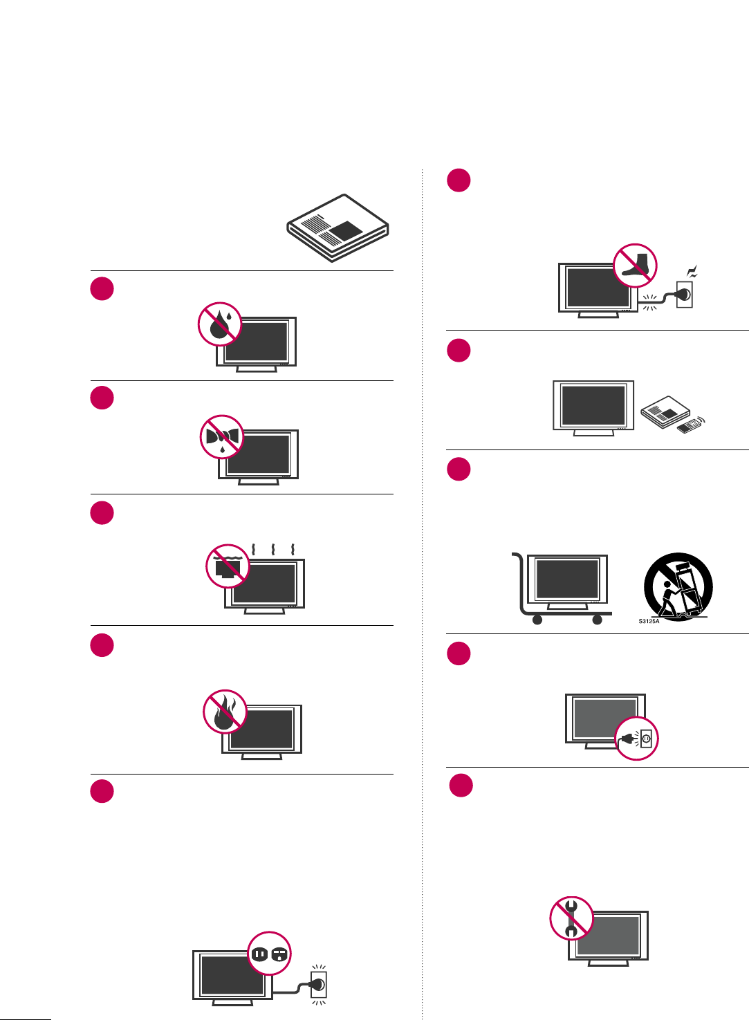
Read these instructions.
Keep these instructions.
Heed all warnings.
Follow all instructions.
Do not use this apparatus near water.
Clean only with dry cloth.
Do not block any ventilation openings. Install in
accordance with the manufacturer’s instructions.
Do not install near any heat sources such as
radiators, heat registers, stoves, or other apparatus
(including amplifiers)that produce heat.
Do not defeat the safety purpose of the polarized
or grounding-type plug. A polarized plug has
two blades with one wider than the other. A
grounding type plug has two blades and a third
grounding prong, The wide blade or the third
prong are provided for your safety. If the provided
plug does not fit into your outlet, consult an
electrician for replacement of the obsolete outlet.
Protect the power cord from being walked on
or pinched particularly at plugs, convenience
receptacles, and the point where they exit from
the apparatus.
Only use attachments/accessories specified by
the manufacturer.
Use only with the cart, stand, tripod, bracket,
or table specified by the manufacturer, or sold
with the apparatus. When a cart is used, use
caution when moving the cart/apparatus
combination to avoid injury from tip-over.
Unplug this apparatus during lighting storms or
when unused for long periods of time.
Refer all servicing to qualified service personnel.
Servicing is required when the apparatus has been
damaged in any way, such as power-supply cord or
plug is damaged, liquid has been spilled or objects
have fallen into the apparatus, the apparatus has
been exposed to rain or moisture, does not operate
normally, or has been dropped.
2
IMPORTANT SAFETY INSTRUCTIONS
SAFETY INSTRUCTIONS
1
2
3
4
5
7
8
6
9
10
3
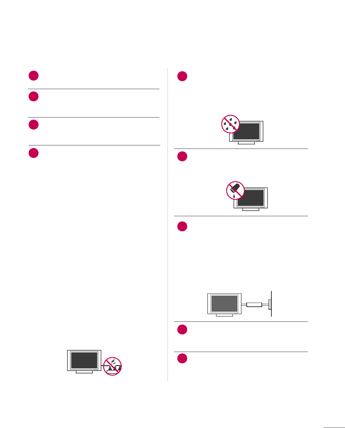
Never touch this apparatus or antenna during a
thunder or lighting storm.
When mounting a TV on the wall, make sure not to
install the TV by the hanging power and signal
cables on the back of the TV.
Do not allow an impact shock or any objects to fall
into the product, and do not drop onto the screen
with something.
CAUTION concerning the Power Cord :
It is recommend that appliances be placed upon a
dedicated circuit; that is, a single outlet circuit which
powers only that appliance and has no additional
outlets or branch circuits. Check the specification
page of this owner's manual to be certain.
Do not connect too many appliances to the same
AC power outlet as this could result in fire or elec-
tric shock.
Do not overload wall outlets. Overloaded wall out-
lets, loose or damaged wall outlets, extension cords,
frayed power cords, or damaged or cracked wire
insulation are dangerous. Any of these conditions
could result in electric shock or fire. Periodically
examine the cord of your appliance, and if its
appearance indicates damage or deterioration,
unplug it, discontinue use of the appliance, and
have the cord replaced with an exact replacement
part by an authorized servicer. Protect the power
cord from physical or mechanical abuse, such as
being twisted, kinked, pinched, closed in a door, or
walked upon. Pay particular attention to plugs, wall
outlets, and the point where the cord exits the
appliance.
Do not make the TV with the power cord plugged
in. Do not use a damaged or loose power cord. Be
sure do grasp the plug when unplugging the power
cord. Do not pull on the power cord to unplug the
TV.
WARNING - To reduce the risk of fire or electrical
shock, do not expose this product to rain, moisture
or other liquids. Do not touch the TV with wet
hands. Do not install this product near flammable
objects such as gasoline or candles or expose the
TV to direct air conditioning.
Do not expose to dripping or splashing and do not
place objects filled with liquids, such as vases, cups,
etc. on or over the apparatus (e.g. on shelves above
the unit).
GGRROOUUNNDDIINNGG
Ensure that you connect the earth ground wire to
prevent possible electric shock. (i.e. a TV with a
three-prong grounded AC plug must be connected
to a three-prong grouned AC outlet) If grounding
methods are not possible, have a qualified electri-
cian install a separate circuit breaker.
Do not try to ground the unit by connecting it to
telephone wires, lightening rods, or gas pipes.
DDIISSCCOONNNNEECCTTIINNGG DDEEVVIICCEE FFRROOMM MMAAIINNSS
Mains plug is the disconnecting device. The plug
must remain readily operable.
Keep the product away from direct sunlight.
12
11
14
13
16
17
18
19
Power
Supply
Short-circuit
Breaker
15
4
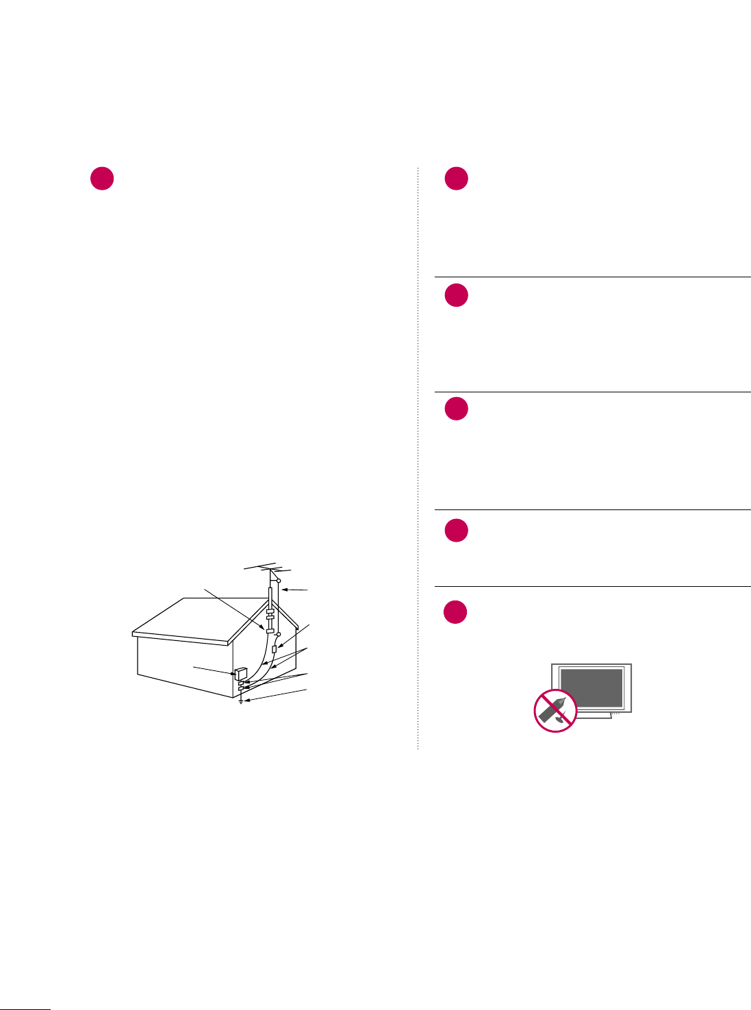
AANNTTEENNNNAASS
OOuuttddoooorr aanntteennnnaa ggrroouunnddiinngg
If an outdoor antenna is installed, follow the precau-
tions below. An outdoor antenna system should not
be located in the vicinity of overhead power lines or
other electric light or power circuits, or where it can
come in contact with such power lines or circuits as
death or serious injury can occur.
Be sure the antenna system is grounded so as to pro-
vide some protection against voltage surges and
built-up static charges.
Section 810 of the National Electrical Code (NEC) in
the U.S.A. provides information with respect to prop-
er grounding of the mast and supporting structure,
grounding of the lead-in wire to an antenna dis-
charge unit, size of grounding conductors, location of
antenna discharge unit, connection to grounding
electrodes and requirements for the grounding elec-
trode.
AAnntteennnnaa ggrroouunnddiinngg aaccccoorrddiinngg ttoo tthhee
NNaattiioonnaall EElleeccttrriiccaall CCooddee,, AANNSSII//NNFFPPAA 7700
Cleaning
When cleaning, unplug the power cord and scrub
gently with a soft cloth to prevent scratching. Do not
spray water or other liquids directly on the TV as
electric shock may occur. Do not clean with chemi-
cals such as alcohol, thinners or benzene.
Moving
Make sure the product is turned off, unplugged
and all cables have been removed. It may take 2 or
more people to carry larger TVs. Do not press
against or put stress on the front panel of the TV.
Ventilation
Install your TV where there is proper ventilation. Do
not install in a confined space such as a bookcase.
Do not cover the product with cloth or other mate-
rials (e.g.) plastic while plugged in. Do not install in
excessively dusty places.
If you smell smoke or other odors coming from the
TV or hear strange sounds, unplug the power cord
contact an authorized service center.
Do not press strongly upon the panel with a hand or
sharp object such as nail, pencil or pen, or make a
scratch on it.
22
20
Antenna Lead in Wire
Antenna Discharge Unit
(NEC Section 810-20)
Grounding Conductors
(NEC Section 810-21)
Ground Clamps
Power Service Grounding
Electrode System (NEC
Art 250, Part H)
Ground Clamp
Electric Service
Equipment
NEC: National Electrical Code
23
24
21
25

5
CONTENTS
WARNING / CAUTION
. . . . . . . . . . . . . . . . . . . . . . . . . . . . 1
SAFETY INSTRUCTIONS
. . . . . . . . . . . . . . . . . . . . . . . . . . 2
FEATURES OF THIS TV
. . . . . . . . . . . . . . . . . . . . . . . . . . . . . 7
PREPARATION
Accessories . . . . . . . . . . . . . . . . . . . . . . . . . . . . . . . . . . . . . . . . . . . . . . . . . . . . . . 8
Front Panel Information . . . . . . . . . . . . . . . . . . . . . . . . . . . . . . . . . . . . . 9
Back Panel Information . . . . . . . . . . . . . . . . . . . . . . . . . . . . . . . . . . . . 10
Stand Instruction . . . . . . . . . . . . . . . . . . . . . . . . . . . . . . . . . . . . . . . . . . . . . 12
Cable Management . . . . . . . . . . . . . . . . . . . . . . . . . . . . . . . . . . . . . . . . . 13
Desktop Pedestal Installation . . . . . . . . . . . . . . . . . . . . . . . . . . . . 14
Swivel Stand . . . . . . . . . . . . . . . . . . . . . . . . . . . . . . . . . . . . . . . . . . . . . . . . . . . . 14
Attaching the TV to a desk . . . . . . . . . . . . . . . . . . . . . . . . . . . . . . . 15
VESA Wall Mounting . . . . . . . . . . . . . . . . . . . . . . . . . . . . . . . . . . . . . . . . 16
Securing the TV to the wall to prevent falling
When the TV is used on a stand
. . . . . . . . . . . . . . . . . . . . . . . . . . 17
Antenna or Cable Connection . . . . . . . . . . . . . . . . . . . . . . . . . . 18
MPI Card Slot / PPV Card Installation . . . . . . . . . . . . . . . 19
EXTERNAL EQUIPMENT SETUP
HD Receiver Setup
- Component Connection . . . . . . . . . . . . . . . . . . . . . . . . . . . 20
- HDMI Connection . . . . . . . . . . . . . . . . . . . . . . . . . . . . . . . . . . . . . 21
- DVI to HDMI Connection . . . . . . . . . . . . . . . . . . . . . . . . . . 22
DVD Setup
- Component Connection . . . . . . . . . . . . . . . . . . . . . . . . . . . . 23
- HDMI Connection . . . . . . . . . . . . . . . . . . . . . . . . . . . . . . . . . . . . 24
VCR Setup
- Antenna Connection . . . . . . . . . . . . . . . . . . . . . . . . . . . . . . . . . 25
- Composite (RCA) Connection . . . . . . . . . . . . . . . . . . . 25
Other A/V Source Setup . . . . . . . . . . . . . . . . . . . . . . . . . . . . . . . . . 26
PC Setup
- VGA (D-Sub 15 pin) Connection . . . . . . . . . . . . . . . 27
- DVI to HDMI Connection . . . . . . . . . . . . . . . . . . . . . . . . . . 28
- Screen Setup for PC mode . . . . . . . . . . . . . . . . . . . . . . . . 29
Audio Out Connection . . . . . . . . . . . . . . . . . . . . . . . . . . . . . . . . . . . . 33
WATCHING TV / CHANNEL CONTROL
Remote Control Functions . . . . . . . . . . . . . . . . . . . . . . . . . . . . . . . 34
Turning On TV . . . . . . . . . . . . . . . . . . . . . . . . . . . . . . . . . . . . . . . . . . . . . . . . 36
Channel Selection . . . . . . . . . . . . . . . . . . . . . . . . . . . . . . . . . . . . . . . . . . . 37
Volume Adjustment . . . . . . . . . . . . . . . . . . . . . . . . . . . . . . . . . . . . . . . . . 37
On-Screen Menus Selection . . . . . . . . . . . . . . . . . . . . . . . . . . . . . 38
Channel Setup
- Auto Scan (Auto Tuning) . . . . . . . . . . . . . . . . . . . . . . . . . . . 39
- Add / Delete Channel (Manual Tuning) . . . . . . 40
- Channel Editing . . . . . . . . . . . . . . . . . . . . . . . . . . . . . . . . . . . . . . . . 41
Channel Label . . . . . . . . . . . . . . . . . . . . . . . . . . . . . . . . . . . . . . . . . . . . . . . . . 42
Input List . . . . . . . . . . . . . . . . . . . . . . . . . . . . . . . . . . . . . . . . . . . . . . . . . . . . . . . . 43
PICTURE CONTROL
Picture Size (Aspect Ratio) Control . . . . . . . . . . . . . . . . . . 44
Preset Picture Settings
- Picture Mode - Preset . . . . . . . . . . . . . . . . . . . . . . . . . . . . . . . 47
- Color Tone - Preset . . . . . . . . . . . . . . . . . . . . . . . . . . . . . . . . . . 48
Manual Picture Adjustment
- Picture Mode - User Mode . . . . . . . . . . . . . . . . . . . . . . . . 49
Picture Improvement Technology . . . . . . . . . . . . . . . . . . . . . 50
Advanced Control - Black (Darkness) Level . . . . . . . 51
Eye Care . . . . . . . . . . . . . . . . . . . . . . . . . . . . . . . . . . . . . . . . . . . . . . . . . . . . . . . . .52
Advanced Control - Film Mode . . . . . . . . . . . . . . . . . . . . . . . . .53
Picture Reset . . . . . . . . . . . . . . . . . . . . . . . . . . . . . . . . . . . . . . . . . . . . . . . . . 54
SOUND & LANGUAGE CONTROL
Auto Volume Leveler (Auto Volume) . . . . . . . . . . . . . . . . . 55
Preset Sound Settings (Sound Mode) . . . . . . . . . . . . . . 56
Sound Setting Adjustment - User Mode . . . . . . . . . . . 57
- SRS TruSurround XT . . . . . . . . . . . . . . . . . . . . . . . . . . . . . . . . . 58
Clear Voice . . . . . . . . . . . . . . . . . . . . . . . . . . . . . . . . . . . . . . . . . . . . . . . . . . . . . 59
Balance . . . . . . . . . . . . . . . . . . . . . . . . . . . . . . . . . . . . . . . . . . . . . . . . . . . . . . . . . . 60
TV Speakers On/Off Setup . . . . . . . . . . . . . . . . . . . . . . . . . . . . . . 61
Audio Reset . . . . . . . . . . . . . . . . . . . . . . . . . . . . . . . . . . . . . . . . . . . . . . . . . . . 62
Stereo/SAP Broadcast Setup . . . . . . . . . . . . . . . . . . . . . . . . . . . 63
Audio Language . . . . . . . . . . . . . . . . . . . . . . . . . . . . . . . . . . . . . . . . . . . . . . 64
On-Screen Menus Language Selection . . . . . . . . . . . . . 65
Caption Mode
- Analog Broadcasting System Captions . . . . . . . 66
- Digital Broadcasting System Captions . . . . . . . . 67
- Caption Option . . . . . . . . . . . . . . . . . . . . . . . . . . . . . . . . . . . . . . . 68
TIME SETTING
Clock Setting
- Auto Clock Setup . . . . . . . . . . . . . . . . . . . . . . . . . . . . . . . . . . . . 69
- Manual Clock Setup . . . . . . . . . . . . . . . . . . . . . . . . . . . . . . . . . 70
Auto On/Off Time Setting . . . . . . . . . . . . . . . . . . . . . . . . . . . . . . 71
Sleep Timer Setting . . . . . . . . . . . . . . . . . . . . . . . . . . . . . . . . . . . . . . . . . 72
Auto Shut-off Setting . . . . . . . . . . . . . . . . . . . . . . . . . . . . . . . . . . . . . . . 73

6
PARENTAL CONTROL / RATINGS
Set Password & Lock System . . . . . . . . . . . . . . . . . . . . . . . . . . . 74
Channel Blocking . . . . . . . . . . . . . . . . . . . . . . . . . . . . . . . . . . . . . . . . . . . . 77
Movie & TV Rating . . . . . . . . . . . . . . . . . . . . . . . . . . . . . . . . . . . . . . . . . . 78
Downloadable Rating . . . . . . . . . . . . . . . . . . . . . . . . . . . . . . . . . . . . . . . 81
External Input Blocking . . . . . . . . . . . . . . . . . . . . . . . . . . . . . . . . . . . . 82
Example Electronic Program Guide . . . . . . . . . . . . . . . . . . . 83
Interactive TV Setup . . . . . . . . . . . . . . . . . . . . . . . . . . . . . . . . . . . . . . . . 84
PIP (Picture-In-Picture) . . . . . . . . . . . . . . . . . . . . . . . . . . . . . . . . . . . . 85
COMMERCIAL MODE SETUP
Installer Overview . . . . . . . . . . . . . . . . . . . . . . . . . . . . . . . . . . . . . . . . . . . . 87
Interactive TV Overview . . . . . . . . . . . . . . . . . . . . . . . . . . . . . . . . . . . 88
Commercial Mode Setup for Master TV . . . . . . . . . . . . 89
TLL-1100A Cloning Connections/Learning Setup
. . . . . . . . . . . . . . . . . . . . . . . . . . . . . . . . . . . . . . . . . . . . . . . . . . . . . . . . . . . . . . . . . . . . . . 90
LT2002 Cloning Connections/Learning Setup . . 91
LT2002 Cloning Learning Setup . . . . . . . . . . . . . . . . . . . . . . 92
Cloning Connections/Teaching Setup . . . . . . . . . . . . . . 93
Installer Menu . . . . . . . . . . . . . . . . . . . . . . . . . . . . . . . . . . . . . . . . . . . . . . . . . 94
Reference: Detailed Instructions For Making A
Master TV . . . . . . . . . . . . . . . . . . . . . . . . . . . . . . . . . . . . . . . . . . . . . . . . . . . . . 10 0
Reference: Procedures for adding Channel Label
Icons/Custom Channel Labels (2-5-4 + MENU
Mode) . . . . . . . . . . . . . . . . . . . . . . . . . . . . . . . . . . . . . . . . . . . . . . . . . . . . . . . . . . 101
Reference: Clonable Menu Features . . . . . . . . . . . . . . . . 102
Reference: Power Saving Setup . . . . . . . . . . . . . . . . . . . . . . . 103
TV Aux Input Configuration . . . . . . . . . . . . . . . . . . . . . . . . . . . 103
TV Camport Auto Sense Operation . . . . . . . . . . . . . . . . 10 4
APPENDIX
Troubleshooting . . . . . . . . . . . . . . . . . . . . . . . . . . . . . . . . . . . . . . . . . . . . 105
Reference: LT2002 Cloning Procedure
Troubleshooting . . . . . . . . . . . . . . . . . . . . . . . . . . . . . . . . . . . . . . . . . . . . 107
Troubleshooting Flow Chart . . . . . . . . . . . . . . . . . . . . . . . . . . . 108
Commercial Mode Check . . . . . . . . . . . . . . . . . . . . . . . . . . . . . . . 109
Glossary of Terms . . . . . . . . . . . . . . . . . . . . . . . . . . . . . . . . . . . . . . . . . . 110
Maintenance . . . . . . . . . . . . . . . . . . . . . . . . . . . . . . . . . . . . . . . . . . . . . . . . . . 111
Product Specifications . . . . . . . . . . . . . . . . . . . . . . . . . . . . . . . . . . . . 111
Programming the Remote Control . . . . . . . . . . . . . . . . . . . 112
IR Codes . . . . . . . . . . . . . . . . . . . . . . . . . . . . . . . . . . . . . . . . . . . . . . . . . . . . . . . 115
7
FEATURES OF THIS TV
is a trademark of SRS Labs, Inc.
TruSurround XT technology is incorporated under
license from SRS Labs, Inc.
Manufactured under license from Dolby Laboratories.
“
Dolby
“and the double-D symbol are trademarks of
Dolby Laboratories.
USB IN
SERVUCE ONLYSERVUCE ONLY
USB port shall be used for software update by service
personnel only.
FOR LCD TV
■
If the TV feels cold to the touch, there may be a small “flicker” when it is turned on. This is normal, there is nothing wrong
with TV.
■
Some minute dot defects may be visible on the screen, appearing as tiny red, green, or blue spots. However, they have no adverse
effect on the monitor's performance.
■
Avoid touching the LCD screen or holding your finger(s) against it for long periods of time. Doing so may produce some
temporary distortion effects on the screen.
On Disposal
The fluorescent lamp used in this product contains a small amount of mercury. Do not dispose of this product with general
household waste. Disposal of this product must be carried out in accordance to the regulations of your local authority.
HDMITM, the HDMI logo and High-Definition
Multimedia Interface are trademarks or registered
trademarks of HDMI Licensing."
8
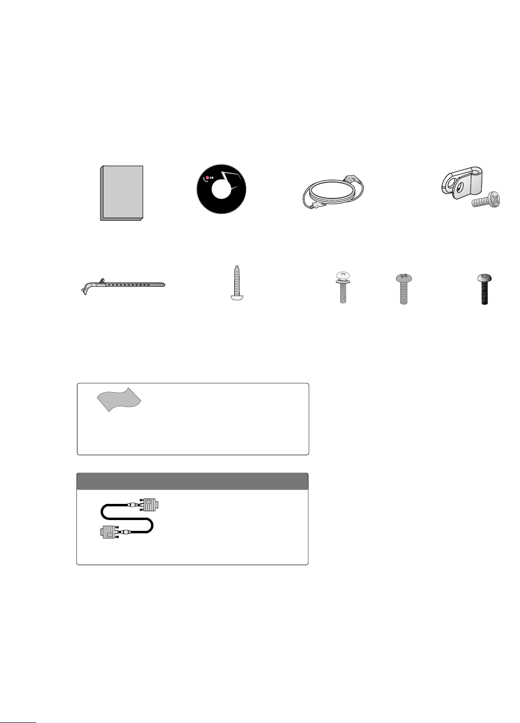
PREPERATION
ACCESSORIES
Ensure that the following accessories are included with your TV. If an accessory is missing, please contact the
dealer where you purchased the TV.
The accessories included may differ from the images below.
Copyright© 2007 LGE,
All Rights Reserved.
Owner’s Manual Power Cord
CD Manual Protective Bracket and
Bolt for Power Cord
(Refer to P.13)
Cable Holder
(Refer to P.13)
* Wipe spots on the exterior only with the pol-
ishing cloth.
* Do not wipe roughly when removing stains.
Excessive pressure may cause scratches or
discoloration.
Polishing Cloth
(This feature is not avail-
able for all models.)
OOppttiioonn EExxttrraass
D-sub 15 pin Cable
When using the VGA (D-sub 15 pin
cable) PC connection, the user
must use shielded signal interface
cables with ferrite cores to maintain
standards compliance.
x 2
Torx plus
Star head screw
(Refer to P.12)
M4xL22
(Machine Screw)
Screw for stand fixing
(Refer to P.15)
Ø
4xL20
(Plastic Screw)
Bolts for stand assembly
(Refer to P.12)
x 4 x 4
M4xL26
(Machine Screw)
Ø
4xL20
(Plastic Screw)
PREPARATION
9
FRONT PANEL INFORMATION
■
Image shown may differ from your TV.
■
NOTE: If your TV has a protection tape attached, remove the tape.
And then wipe the TV with a cloth (If a polishing cloth is included with your TV, use it).
POWER Button
Power/Standby Indicator
Illuminates red in standby mode.
Illuminates blue when the set is switched on.
CH
VOL
MENU
INPUT
ENTER
VOLUME (+, -)
Buttons
ENTER Button
MENU Button
INPUT Button
Remote Control Sensor
CHANNEL(+, -)
Buttons
Stand
PREPARATION
10
PREPARATION
■
Image shown may differ from your TV.
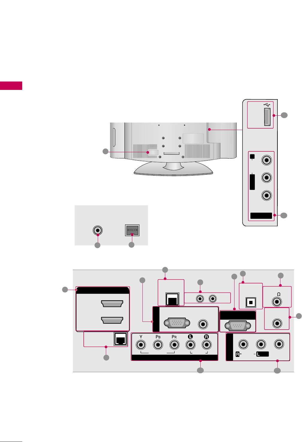
BACK PANEL INFORMATION
R
AV IN 2
L/MONO
R
AUDIO
VIDEO
USB
SERVICE ONLY
REMOTE
CONTROL OUT
OPTICAL
DIGITAL
AUDIO OUT
AV IN 1
AUDIO
VIDEO
MONO
/
UPDATE
RESET
LAN
(SERVICE ONLY)
RGB IN
RGB(PC) AUDIO
(RGB/DVI)
COMPONENT IN
VIDEO
AUDIO
HDMI/DVI IN
2
1(DVI)
RJP
INTERFACE
SPEAKER OUT
8
RS-232C IN
(SERVICE ONLY)
R
8
24
R
( )
ANTENNA IN
ANTENNA IN
M.P.I.
M.P.I.
7
1
3
5
6
9
10 11
12
13
15
14
11

PREPARATION
11
REMOTE CONTROL OUT
IR output for controlling an auxiliary device.
RJP INTERFACE (REMOTE JACK PACK PORT)
Connect to remote jack pack control output port.
COMPONENT IN
Analog Connection.
Supports HD.
Uses a red, green, and blue cable for video & a red
and white cable for audio.
AV (Audio/Video) IN
Analog composite connection. Supports standard
definition video only (480i).
Used for PC/DTV audio input jack.
USB SERVICE ONLY
Used for software updates.
ANTENNA IN
Connect over-the air signals to this jack.
M.P. I.
Power Cord Socket
For operation with AC power.
Caution: Never attempt to operate the TV on DC
power.
HDMI/DVI IN
Digital Connection. Supports HD video and Digital
audio.
Accepts DVI video using an adapter or HDMI to
DVI cable (not included)
LAN (SERVICE ONLY)
Connect to control network.
UPDATE
Software downloads and debug mode enable/dis-
able.
RESET
Hardware reset to PTC microcontroller.
OPTICAL DIGITAL AUDIO OUT
Digital audio output for use with amps and home
theater systems.
Includes an optical connection.
Note: In standby mode, these ports do not work.
SPEAKER OUT 8Ω
Connect to external speaker input.
RGB IN (PC)
Analog PC Connection. Uses a D-sub 15 pin cable
(VGA cable).
AUDIO (RGB/DVI)
1/8” headphone jack for analog PC audio input.
RS-232C IN (SERVICE ONLY)
Used for software updates.
1
2
3
4
5
9
8
6
7
10
11
12
13
14
15
PREPARATION
12
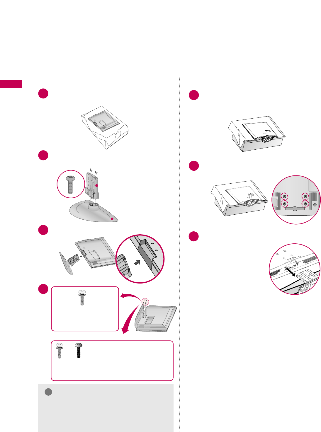
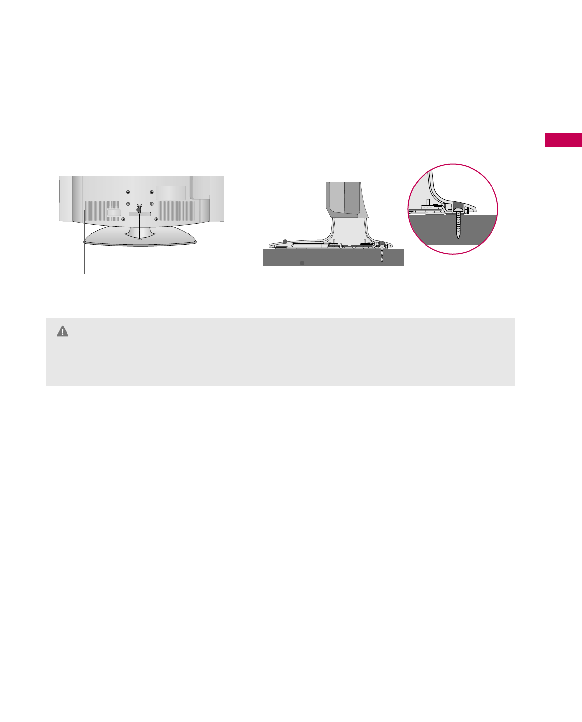
STAND INSTRUCTION
PREPARATION
Carefully place the TV screen side down on a
cushioned surface to protect the screen from
damage.
Assemble the parts of the SSTTAANNDD BBOODDYY
with CCOOVVEERR BBAASSEEof the TV.
1
2
Insert the stand as shown.
3
SSTTAANNDD BBOODDYY
CCOOVVEERR BBAASSEE
■
Image shown may differ from your TV.
GGMake sure the screws in the stand are fully
tightened. (If not tightened fully, the product
could tilt forward and fall). But do not over
tighten, over-tightening can damage the threads
on the screws.
NOTE
!
DETACHMENT
Carefully place the TV screen side down on a
cushioned surface to protect the screen from
damage.
1
Remove the four screws that hold the base on.
2
Detach the stand from TV.
3
INSTALLATION
4
or
x 4
Tighten the stand with the
four screws (provided as parts
of the TV).
Tighten the two of these four screws
and the two Torx plus star head screws
(provided as parts of the TV) to secure the TV. Tighten
the two Torx plus star head screws with a star head dri-
ver bit (not provided as parts of the TV).
x 2 x 2
PREPARATION
13
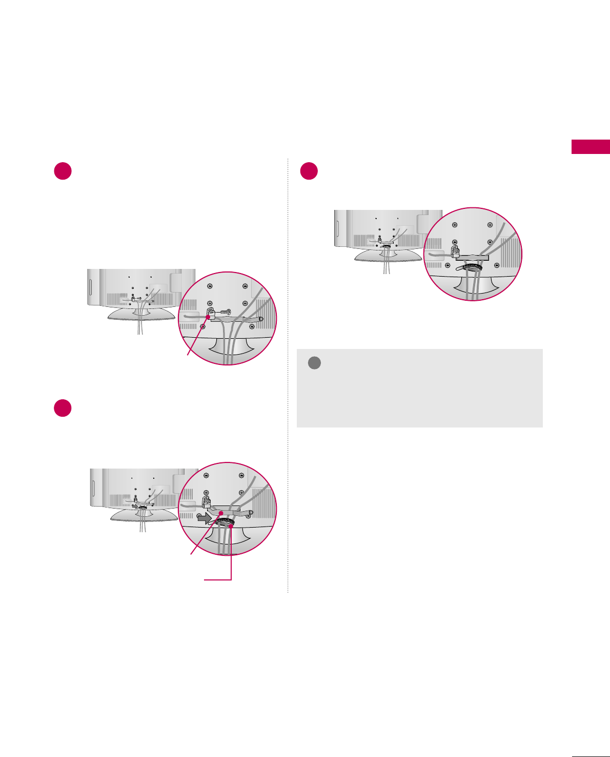
CABLE MANAGEMENT
■
Image shown may differ from your TV.
Connect the cables as necessary.
To connect additional equipment, see the
EXTERNAL EQUIPMENT SETUP section.
Secure the power cable with the
PROTECTIVE BRACKET and the screw as
shown. It will help prevent the power cable
from being removed by accident.
Install the CABLE MANAGEMENT CLIP as
shown.
If your TV has the CABLE HOLDER, install it
as shown and bundle the cables.
1
2
Put the cables inside the CABLE MANAGEMENT
CLIP and snap it closed.
3
PROTECTIVE BRACKET
(This feature is not available
for all models.) GGDo not hold the CABLE MANAGEMENT CLIP
when moving the TV.
- If the TV is dropped, you may be injured or the
product may be broken.
NOTE
!
CABLE MANAGEMENT CLIP
CABLE HOLDER
PREPARATION
14
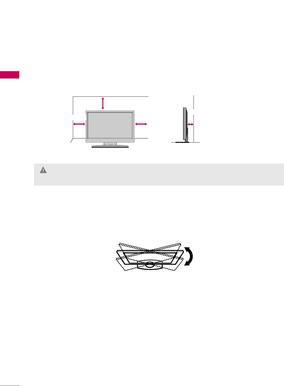
PREPARATION
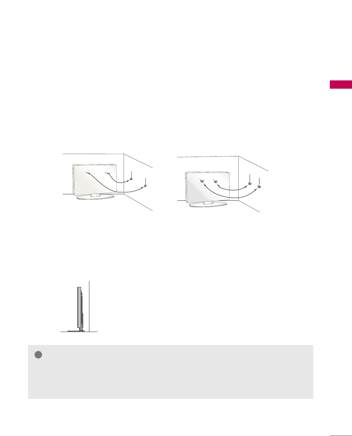
DESKTOP PEDESTAL INSTALLATION
For proper ventilation, allow a clearance of 4 inches on all four sides.
■
Image shown may differ from your TV.
* This feature is not available for all models.
4 inches
4 inches
4 inches
4 inches
SWIVEL STAND
The TV can be conveniently swivelled on its stand 90° to the left or right to provide the optimum viewing angle.
GGEnsure adequate ventilation by following the clearance recommendations.
GGDo not mount near or above any type of heat source.
CAUTION
PREPARATION
15
ATTACHING THE TV TO A DESK
The TV must be attached to a desk so it cannot be pulled in a forward/backward direction, potentially causing
injury or damaging the product. Use only the included screw.
GGTo prevent TV from falling over, the TV should be securely attached to the floor/wall per installation
instructions. Tipping, shaking, or rocking the TV may cause injury.
WARNING
1-Screw
(provided as parts of the product)
Desk
Stand
PREPARATION
16
PREPARATION
VESA WALL MOUNTING
Install your wall mount on a solid wall perpendicular to the floor. When attaching to other building materi-
als, please contact your nearest dealer.
If installed on a ceiling or slanted wall, it may fall and result in severe personal injury.
We recommend that you use an LG brand wall mount when mounting the TV to a wall.
GGDo not install your wall mount kit while the TV is plugged in. It may result in personal injury due to electric
shock.
CAUTION
GGScrew length needed depends on the wall mount
used. For further information, refer to the instruc-
tions included with the mount.
GGStandard dimensions for wall mount kits are shown
in the table.
GGWhen purchasing our wall mount kit, a detailed
installation manual and all parts necessary for
assembly are provided.
GGDo not use screws longer then the standard dimen-
sion, as they may cause damage to the inside to
the TV.
GGFor wall mounts that do not comply with the VESA
standard screw specifications, the length of the
screws may differ depending on their specifica-
tions.
GGDo not use screws that do not comply with the
VESA standard screw specifications.
Do not tighten the screws too much. It may dam-
age the TV or allow the TV to a fall and cause per-
sonal injury. LG is not liable for these kinds of acci-
dents.
GGLG is not liable for TV damage or personal injury
when a non-VESA or non specified wall mount is
used or the consumer fails to follow the TV installa-
tion instructions.
NOTE
!
Product Model VESA
(A *B) Standard Screw Quantity
32LG700H
37LG700H
42LG700H
200 * 100 M6 4
LCD TV
AA
BB
GGTo prevent injury, this apparatus must be securely attached to the wall in accordance with the installa-
tion instructions.
WARNING
200 * 200
200 * 200
M6
M6 4
4
PREPARATION
17
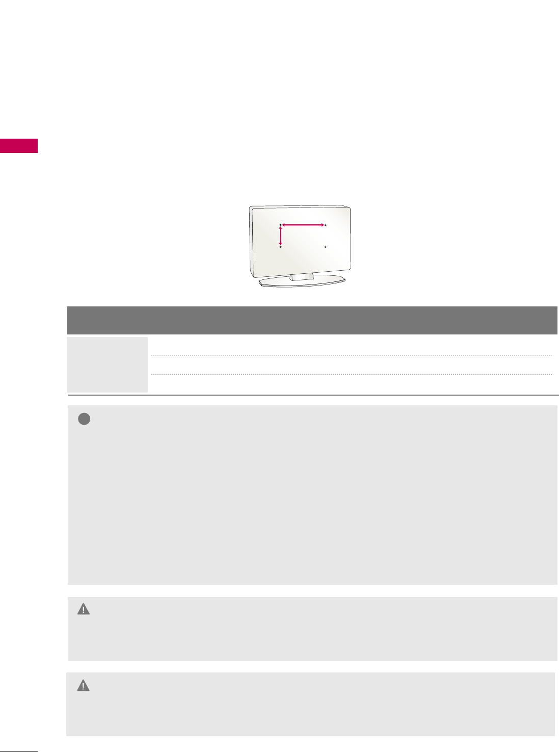
SECURING THE TV TO THE WALL TO PREVENT FALLING
WHEN THE TV IS USED ON A STAND
We recommend that you set the TV close to a wall so it cannot fall over if pushed backwards.
Additionally, we recommend that the TV be attached to a wall so it cannot be pulled in a forward direction,
potentially causing injury or damaging the product.
Caution: Please make sure that children don’t climb on or hang from the TV.
■Insert eye-bolts (or TV brackets and bolts) to attach the product to the wall as shown in the picture.
*If your product has the bolts in the eye-bolts position before inserting the eye-bolts, loosen the bolts.
* Insert the eye-bolts or TV brackets/bolts and tighten them securely in the upper holes.
Secure the wall brackets with screws (sold separately) to the wall. Match the height of the bracket that
is mounted on the wall to the holes in the product.
Ensure the eye-bolts or brackets are tightened securely.
■Use a sturdy rope or cord (sold separately) to tie the product. It is
safer to tie the rope so it becomes horizontal between the wall and
the product (the less slack in the rope, the better).
■
You should purchase necessary components to prevent TV from falling off of the stand.
■
Image shown may differ from your TV.
* This feature is not available for all models.
GGUse a platform or cabinet strong enough and large enough to support the size and weight of the TV.
GGTo use the TV safely, make sure that the height of the bracket on the wall and the one on the TV are
the same.
NOTE
!
ANTENNA IN
ANTENNA IN
PREPARATION
18
PREPARATION
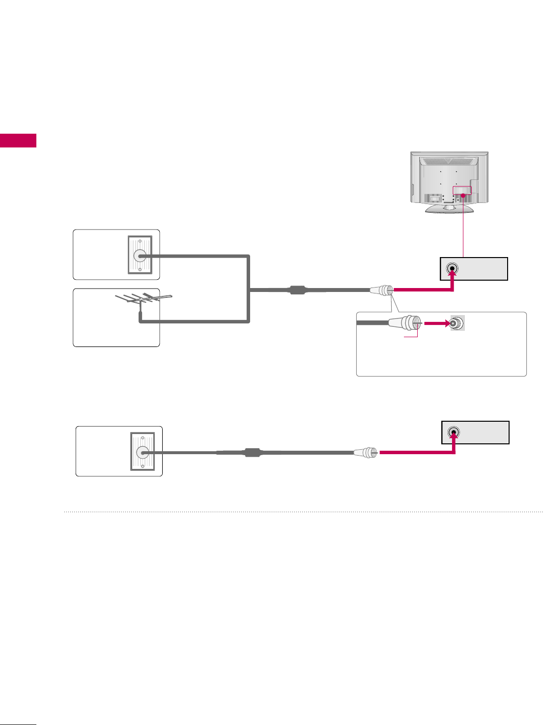
ANTENNA OR CABLE CONNECTION
1. Antenna (Analog or Digital)
Wall Antenna Socket or Outdoor Antenna without a Cable Box
Connection.
For optimum picture quality, adjust the direction if needed.
2. Cable
Wall
Antenna
Socket
Outdoor
Antenna
(VHF, UHF)
Cable TV
Wall Jack
Multi-family Dwellings/Apartments
(Connect to wall antenna socket)
RF Coaxial Wire (75 ohm)
RF Coaxial Wire (75 ohm)
Single-family Dwellings /Houses
(Connect to wall jack for outdoor antenna)
Be careful not to bend the copper wire
when connecting the antenna.
Copper Wire
■To improve the picture quality in a poor signal area, please purchase a signal amplifier and install properly.
■If the antenna needs to be split for two TV’s, install a 2-Way Signal Splitter.
■If the antenna is not installed properly, contact your dealer for assistance.
R
( )
■To prevent damage do not connect to the power outlet until all connections are made between the devices.
PREPARATION
19
MPI CARD SLOT / PPV CARD INSTALLATION
1. Remove the two MPI card retainer screws.
2. Pull out current MPI card far enough so that the RF cable can be detached from the old card.
2. Detach RF cable.
3. Place new PPV card into slot and slide it in far enough to reconnect RF cable.
4. Insert card all the way into the slot making sure it is fully seated into back plane connector.
5. Replace the two card retainer screws.
The MPI card is equipped with an RF jack for antenna/cable signal source connection.
The MPI card slot is also available for installing a PPV (Pay-Per-View) card.
MPI Card Removal / PPV Card Installation
RF CABLE
RF cable needs to be
disconnected to remove
current card.
ANTENNA IN M.PM.P.I.
M.P. I.
Card Slot
PREPARATION
20
HD RECEIVER SETUP
EXTERNAL EQUIPMENT SETUP
This TV can receive Digital Over-the-air or Digital Cable signals without an external digital set-top box. However,
if you do receive digital signals from a digital set-top box or other digital external device, refer to the figure as
shown below.
Component Connection
1. How to connect
Connect the video outputs (Y, PB, PR)of the digital set-
top box to the CCOOMMPPOONNEENNTT IINN VVIIDDEEOOjacks on
the TV. Match the jack colors (Y = green, PB= blue, and
PR= red).
Connect the audio output of the digital set-top box to
the CCOOMMPPOONNEENNTT IINN AAUUDDIIOOjacks on the TV.
2
1
2. How to use
■Turn on the digital set-top box.
(Refer to the owner’s manual for the digital set-top box.)
■Select CCoommppoonneennttinput source using the IINNPPUUTT button
on the remote control.
■To prevent the equipment damage, never plug in any power cords until you have finished connecting all equipment.
■This part of EXTERNAL EQUIPMENT SETUP mainly uses the picture for 42LG700H model.
UPDA
RESET
LAN
(SERVICE ONLY)
RGB IN
RGB(PC) AUDIO
(RGB/DVI)
COMPONENT IN
VIDEO
AUDIO
R
(S
Y L RP
B
P
R
12
Y, CB/PB, CR/PR
Supported Resolutions
Horizontal Vertical
Frequency(KHz)Frequency(Hz)
15.73 59.94
15.73 60.00
31.47 59.94
31.47 60.00
44.96 59.94
45.00 60.00
33.72 59.94
33.75 60.00
Resolution
720x480i
720x480p
1280x720p
1920x1080i
Signal
480i
480p
720p
1080 i
1080 p
Component
Yes
Yes
Yes
Yes
No
HDMI
No
Yes
Yes
Yes
No
EXTERNAL EQUIPMENT SETUP
21
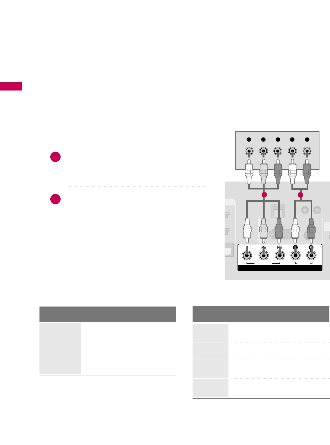
HDMI Connection
Connect the digital set-top box to HHDDMMII//DDVVII IINN
jack on the TV.
No separate audio connection is necessary.
HDMI supports both audio and video.
1. How to connect
2. How to use
■Turn on the digital set-top box.
(Refer to the owner’s manual for the digital set-top box.)
■Select HHDDMMIIinput source with using the IINNPPUUTTbutton
on the remote control.
2
1
HDMI-DTV
RESET
UPDATE
(
RGB IN
CO
VID
HDMI/DVI IN
2
1(DVI)
RJP
INTERFACE
HDMI-DTV OUTPUT
1
Horizontal Vertical
Frequency(KHz)Frequency(Hz)
31.47 59.94
31.47 60.00
44.96 59.94
45.00 60.00
33.72 59.94
33.75 60.00
Resolution
720x480p
1280x720p
1920x1080i
EXTERNAL EQUIPMENT SETUP
22
EXTERNAL EQUIPMENT SETUP
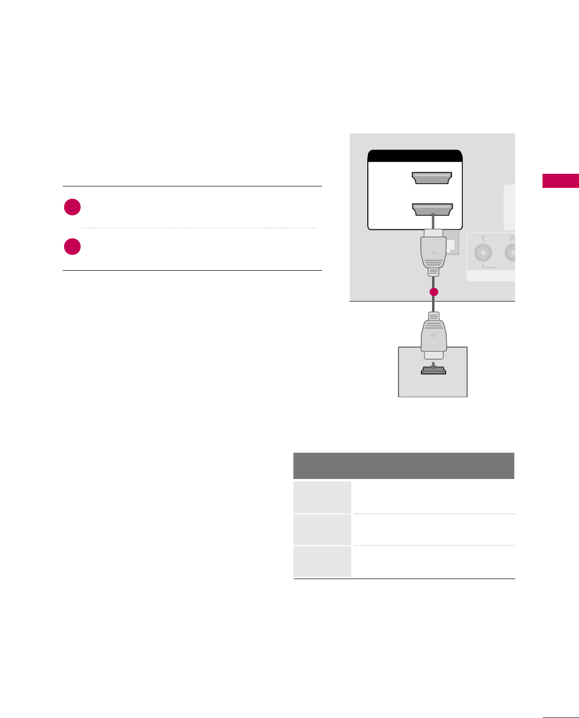
DVI to HDMI Connection
RESET
LAN
(SERVICE ONLY)
RGB IN
RGB(PC)
COMPONENT IN
VIDEO
RJP
INTERFACE
AUDIO
AUDIO
(RGB/DVI)
HDMI/DVI IN
2
1(DVI)
LR
DVI-DTV OUTPUT LR
1
2
GGA DVI to HDMI cable or adapter is required for this
connection. DVI doesn't support audio, so a separate
audio connection is necessary.
NOTE
!
Connect the DVI output of the digital set-top box to
the HHDDMMII//DDVVII IINNjack on the TV.
Connect the audio output of the digital set-top box to
the AAUUDDIIOO((RRGGBB//DDVVII))jack on the TV.
1. How to connect
2. How to use
■Turn on the digital set-top box. (Refer to the owner’s man-
ual for the digital set-top box.)
■Select the HHDDMMIIinput source on the TV using the IINNPPUUTT
button on the remote control.
2
1
EXTERNAL EQUIPMENT SETUP
23
DVD SETUP
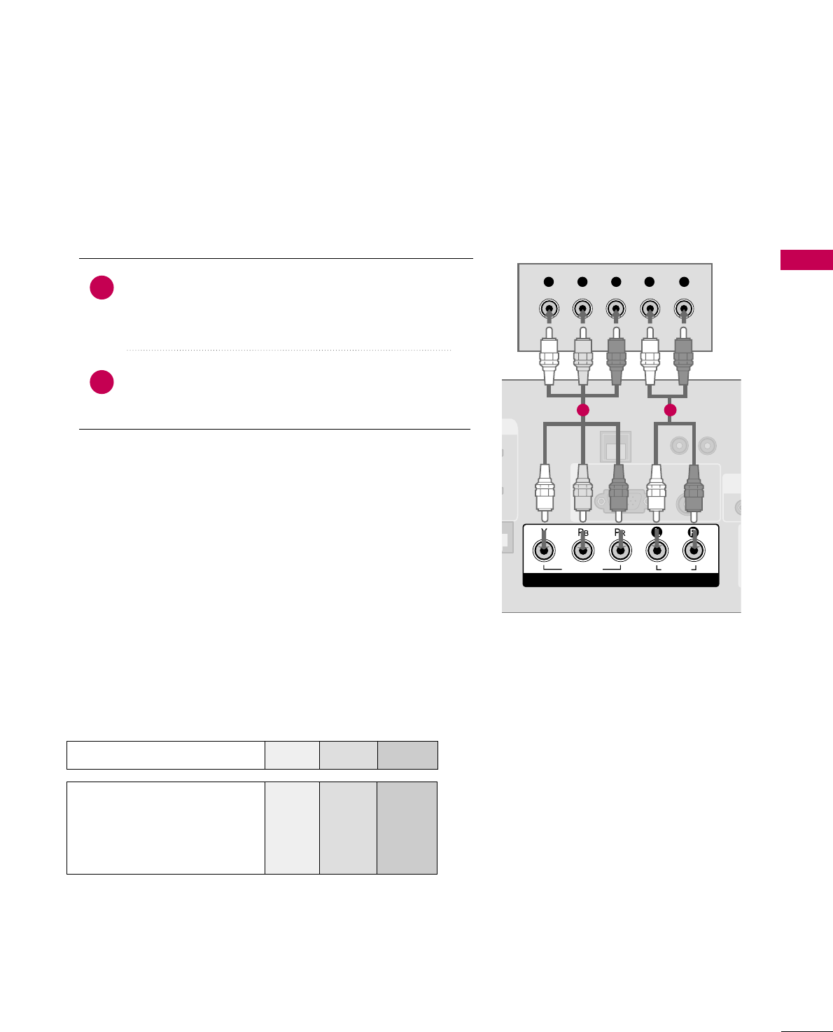
Component Connection
Component Input ports
To get better picture quality, connect a DVD player to the component input ports as shown below.
Component ports on the TV
YPBPR
Video output ports
on DVD player
Y
Y
Y
Y
PB
B-Y
Cb
Pb
PR
R-Y
Cr
Pr
Connect the video outputs (Y, PB, PR)of the DVD to the
CCOOMMPPOONNEENNTT IINN VVIIDDEEOOjacks on the TV.
Match the jack colors (Y = green, PB= blue, and PR= red).
Connect the audio outputs of the DVD to the
CCOOMMPPOONNEENNTT IINN AAUUDDIIOOjacks on the TV.
1. How to connect
2. How to use
■Turn on the DVD player, insert a DVD.
■Select the CCoommppoonneennttinput source on the TV using the
IINNPPUUTTbutton on the remote control.
■Refer to the DVD player's manual for operating instructions.
2
1
UPDAT
RESET
LAN
(SERVICE ONLY)
RGB IN
RGB(PC) AUDIO
(RGB/DVI)
COMPONENT IN
VIDEO
AUDIO
R
(SE
Y L RP
B
P
R
1 2
EXTERNAL EQUIPMENT SETUP
24
EXTERNAL EQUIPMENT SETUP
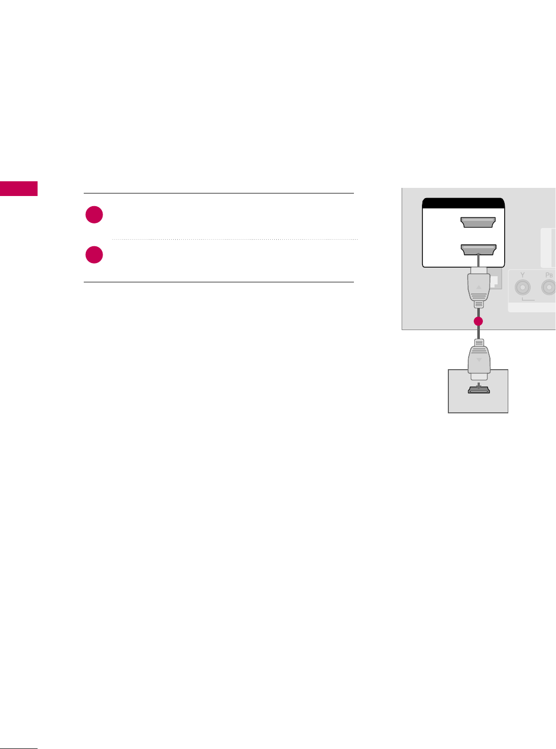
HDMI Connection
Connect the HDMI output of the DVD to the
HHDDMMII//DDVVII IINNjack on the TV.
No separate audio connection is necessary.
HDMI supports both audio and video.
1. How to connect
2. How to use
■Select the HHDDMMII input source on the TV using the
IINNPPUUTTbutton on the remote control.
■Refer to the DVD player's manual for operating instructions.
2
1
(S
RGB IN
COM
VIDEO
HDMI/DVI IN
2
1(DVI)
RJP
INTERFACE
HDMI OUTPUT
1
EXTERNAL EQUIPMENT SETUP
25
VCR SETUP
Antenna Connection
■To avoid picture noise (interference), leave an adequate distance between the VCR and TV.
■If the 4:3 picture format is used; the fixed images on the sides of the screen may remain visible on the
screen. This phenomenon is common to all TVs and is not covered by warranty.
L R
S-VIDEO VIDEO
OUTPUT
SWITCH
ANT IN
ANT OUT
ANTENNA IN M.P.I.
( )
( )
Wall Jack
Antenna
1
2
Connect the RF antenna out socket of the
VCR to the AANNTTEENNNNAA IINNsocket on the
TV.
Connect the antenna cable to the RF
antenna in socket of the VCR.
1. How to connect
2. How to use
■Set VCR output switch to 3 or 4 and then
tune TV to the same channel number.
■Insert a video tape into the VCR and press
PLAY on the VCR. (Refer to the VCR owner’s
manual.)
2
1
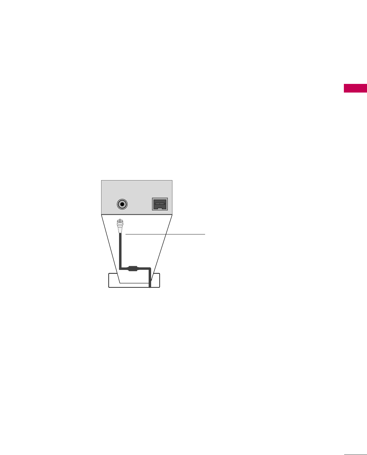
Composite (RCA) Connection
Connect the AAUUDDIIOO/VVIIDDEEOOjacks between TV and
VCR. Match the jack colors (Video = yellow, Audio Left
= white, and Audio Right = red)
1. How to connect
2. How to use
■Insert a video tape into the VCR and press PLAY on the
VCR. (Refer to the VCR owner’s manual.)
■Select the AAVV11input source on the TV using the IINNPPUUTT
button on the remote control.
■If connected to AAVV IINN22, select AAVV22input source on the TV
(Except 22LG3DCH)
.
1
GGIf you have a mono VCR, connect the audio cable
from the VCR to the AAUUDDIIOO LL((MMOONNOO))jack of
the TV.
NOTE
!
AUDIO
VIDEO
MONO
/
L
RS-VIDEO
VIDEO
OUTPUT
SWITCH
ANT IN
ANT OUT
AV IN 1
1
EXTERNAL EQUIPMENT SETUP
26
EXTERNAL EQUIPMENT SETUP
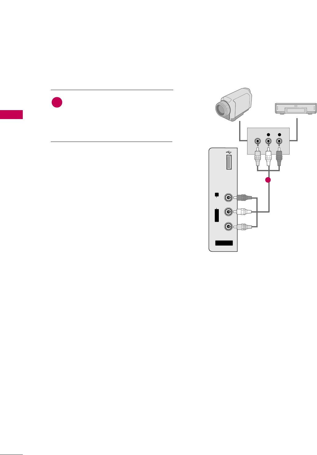
OTHER A/V SOURCE SETUP
AV IN 2
L/MONO
R
AUDIO
VIDEO
USB
SERVICE ONLY
L R
VIDEO
Camcorder
Video Game Set
Connect the AAUUDDIIOO/VVIIDDEEOOjacks
between TV and external equipment.
Match the jack colors
.
(Video = yellow, Audio Left = white, and
Audio Right = red)
1. How to connect
2. How to use
■Select the AAVV22input source on the TV using the
IINNPPUUTTbutton on the remote control.
■If connected to AAVV IINN11input, select the AAVV11
input source on the TV.
■Operate the corresponding external equipment.
1
1
EXTERNAL EQUIPMENT SETUP
27
PC SETUP
GGTo get the the best picture quality, adjust the PC
graphics card to 1360x768.
GGDepending on the graphics card, DOS mode may
not work if a HDMI to DVI Cable is in use.
GGIn PC mode, there may be noise associated with the
resolution, vertical pattern, contrast or brightness.
If noise is present, change the PC output to anoth-
er resolution, change the refresh rate to another
rate or adjust the brightness and contrast on the
PICTURE menu until the picture is clear.
GGAvoid keeping a fixed image on the screen for a
long period of time. The fixed image could become
permanently imprinted on the screen.
GGThe synchronization input form for Horizontal and
Vertical frequencies is separate.
GGDepending on the graphics card, some resolution
settings may not allow the image to be positioned
on the screen properly.
NOTES
!
Supported Display Specifications
(RGB-PC, HDMI-PC)
This TV provides Plug and Play capability, meaning that the PC adjusts automatically to the TV's settings.
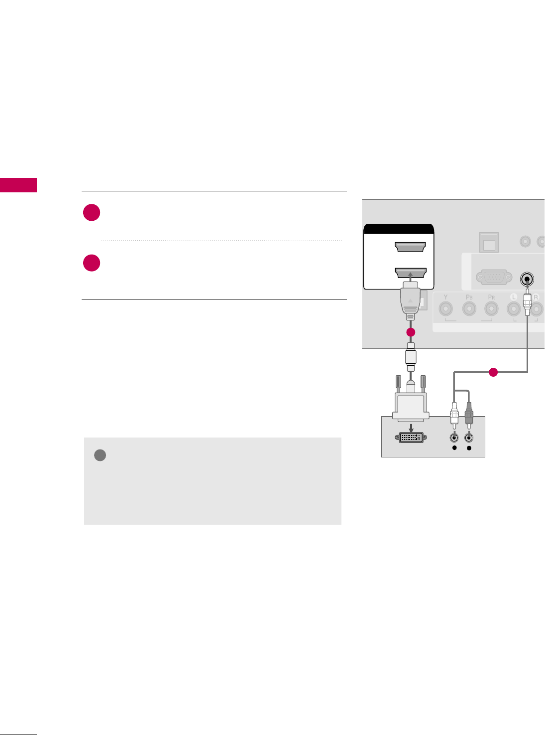
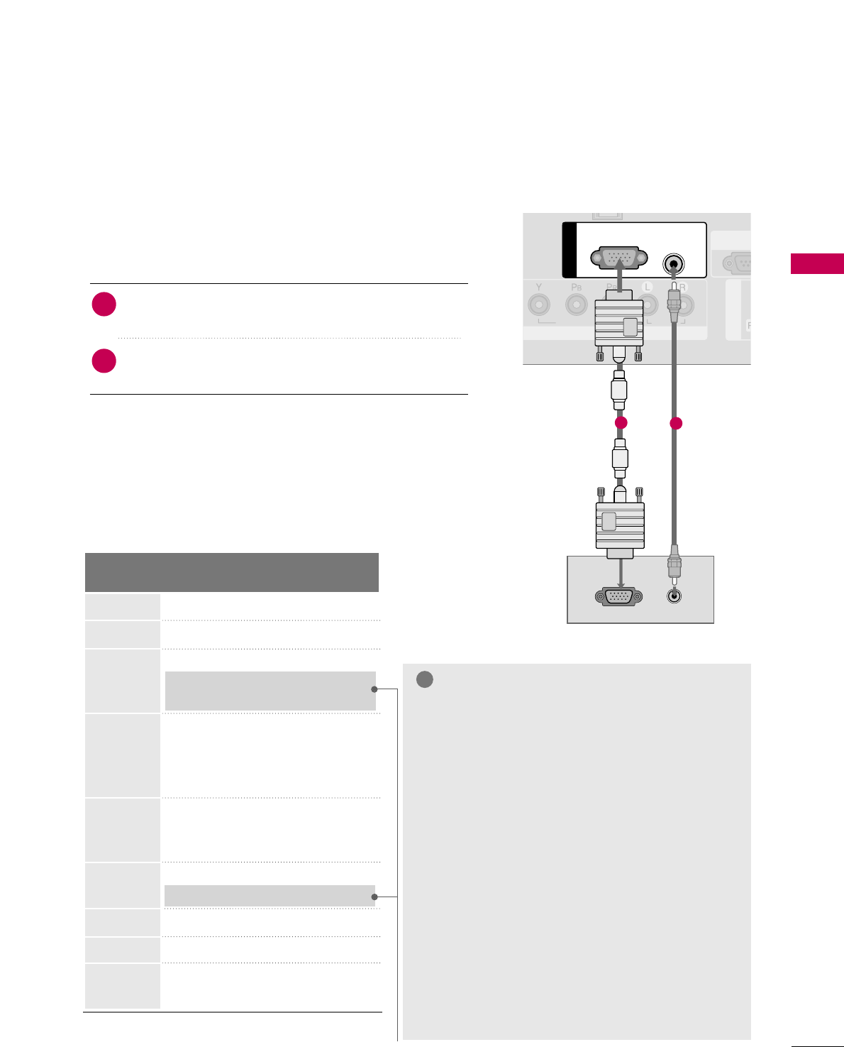
VGA (D-Sub 15 pin) Connection
AV IN 1
COMPONENT IN
VIDEO
RS-23
(SERVIC
AUDIO
RGB IN
RGB OUTPUT AUDIO
RGB(PC) AUDIO
(RGB/DVI)
12
2. How to use
■Turn on the PC and the TV.
■Select the RRGGBBinput source on the TV using the IINNPPUUTT
button on the remote control.
Connect the VGA output of the PC to the RRGGBB((PPCC))
jack on the TV.
Connect the PC audio output to the AAUUDDIIOO((RRGGBB//DDVVII))
jack on the TV.
1. How to connect
2
1
Resolution
720x400
1360x768
640x350
640x480
800x600
1024x768
1366x768
1280x768
* Only RGB-PC mode
1280x1024
Horizontal Vertical
Frequency(KHz)Frequency(Hz)
31.468 70.09
31.469 70.08
31.469 59.94
37.861 72.80
37.500 75.00
35.156 56.25
37.879 60.31
48.077 72.18
46.875 75.00
48.363 60.00
56.476 70.06
60.023 75.02
47.776 59.870
60.289 74.893
47.712 60.015
47.130 59.658
63.981 60.020
79.976 75.025
EXTERNAL EQUIPMENT SETUP
28
EXTERNAL EQUIPMENT SETUP
DVI to HDMI Connection
U
RESET
LAN
(SERVICE ONLY)
COMPONENT IN
VIDEO
RJP
INTERFACE
AUDIO
HDMI/DVI IN
2
1(DVI)
DVI-PC OUTPUT AUDIO
RGB(PC)
AUDIO
(RGB/DVI)
RGB IN
1
2
2. How to use
■Turn on the PC and the TV.
■Select the HHDDMMIIinput source on the TV using the IINNPPUUTT
button on the remote control.
Connect the DVI output of the PC to the HHDDMMII//DDVVII
IINN jack on the TV.
Connect the PC audio output to the AAUUDDIIOO((RRGGBB//DDVVII))
jack on the TV.
1. How to connect
2
1
EXTERNAL EQUIPMENT SETUP
29
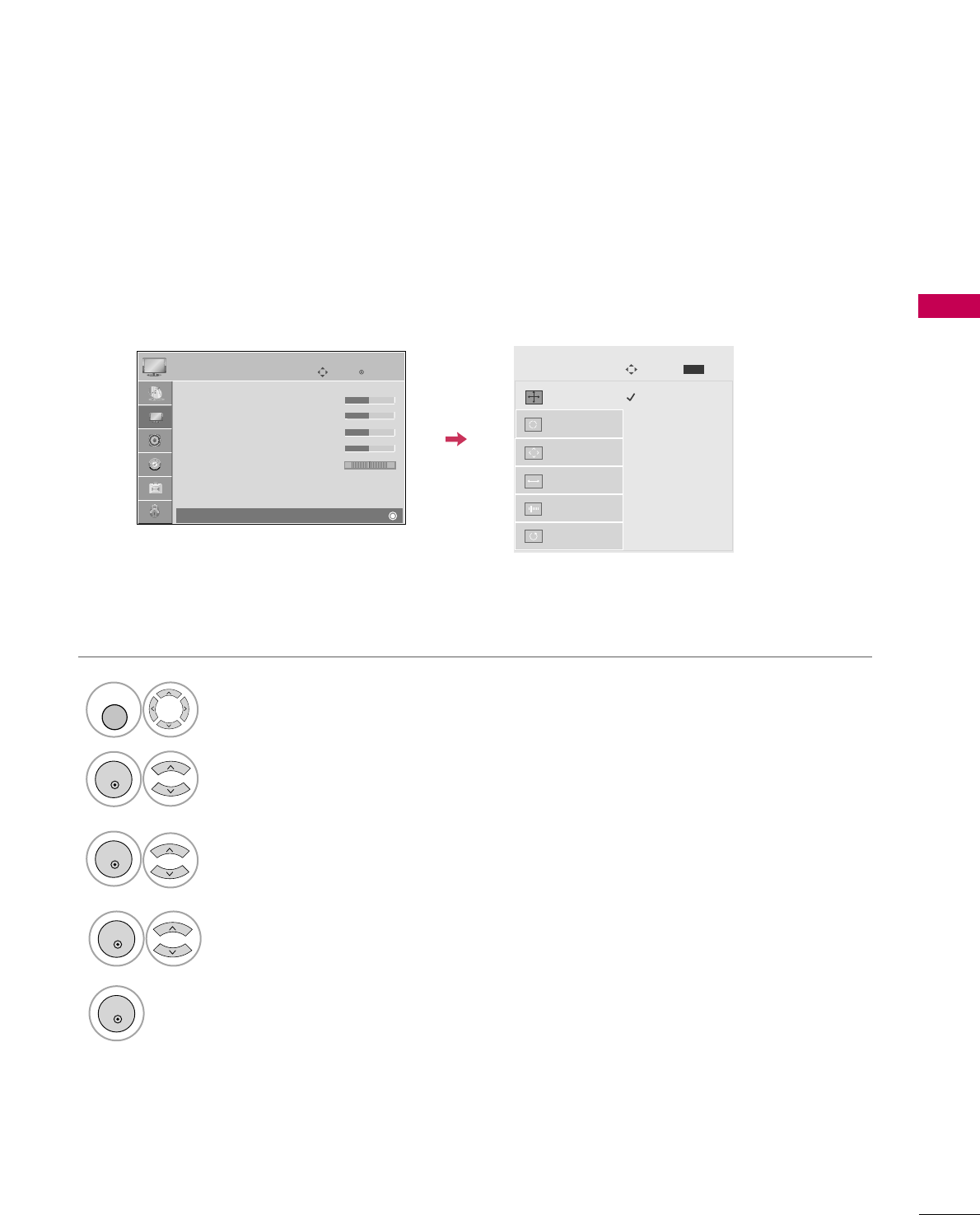
Screen Setup for PC mode
1024 x 768
1280 x 768
1360 x 768
1366 x 768
Auto config.
Resolution
G
Position
Size
Phase
Reset
Screen
Move
Prev.
MENU
Selecting Resolution
You can choose the resolution in RGB-PC mode.
The PPoossiittiioonn, PPhhaassee, and SSiizzeecan also be adjusted.
Enter
Move
PICTURE
E
RG
• Contrast 50
• Brightness 50
• Sharpness 50
• Color 50
• Tint 0
• Advanced Control
• Reset
Screen (RGB-PC)
Select PPIICCTTUURREE.
Select RReessoolluuttiioonn.
1
MENU
3
ENTER
4
Select SSccrreeeenn ((RRGGBB--PPCC)).
2
ENTER
5
Select the desired resolution.
ENTER
ENTER
EXTERNAL EQUIPMENT SETUP
30
EXTERNAL EQUIPMENT SETUP
Auto Configure
Automatically adjusts picture position and minimizes image instability. After adjustment, if the image is still
not correct, try using the manual settings or a different resolution or refresh rate on the PC.
Auto config. G
Resolution
Position
Size
Phase
Reset
Screen
Move
Prev.
MENU
To Set
• If the position of the image is still not
correct, try Auto adjustment again.
• If picture needs to be adjusted again
after Auto adjustment in RGB-PC, you
can adjust the PPoossiittiioonn, SSiizzee or
PPhhaassee.
Yes No
Select PPIICCTTUURREE.
Select AAuuttoo ccoonnffiigg...
1
MENU
3
ENTER
4
Select SSccrreeeenn ((RRGGBB--PPCC)).
2
ENTER
5
ENTER
Start Auto Configuration.
Select YYeess.
ENTER
Enter
Move
PICTURE
E
RG
• Contrast 50
• Brightness 50
• Sharpness 50
• Color 50
• Tint 0
• Advanced Control
• Reset
Screen (RGB-PC)
EXTERNAL EQUIPMENT SETUP
31
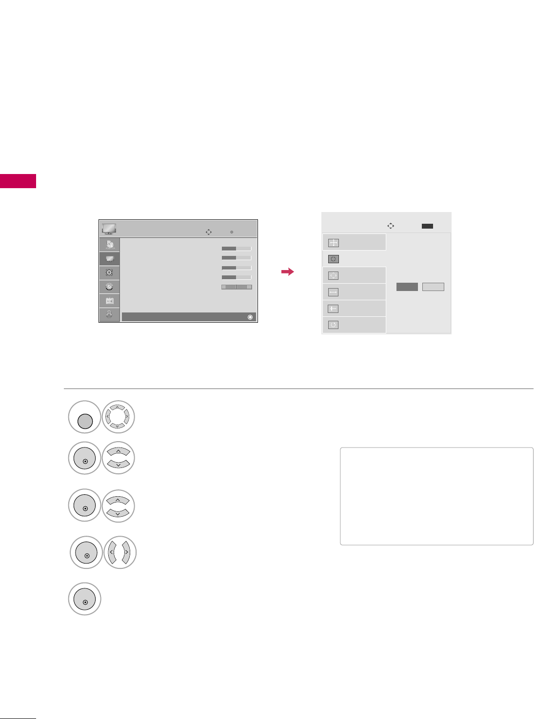
Adjustment for screen Position, Size, and Phase
If the picture is not clear after auto adjustment and especially if characters are still trembling, adjust the picture
phase manually.
This feature operates only in RGB-PC mode.
Auto config.
Resolution
Position
G
Size
Phase
Reset
GF
D
E
Screen
Move
Prev.
MENU
■PPoossiittiioonn: This function is to adjust pic-
ture to left/right and up/down as you
prefer.
■SSiizzee: This function is to minimize any
vertical bars or stripes visible on the
screen background. And the horizontal
screen size will also change.
■PPhhaassee: This function allows you to
remove any horizontal noise and clear or
sharpen the image of characters.
Select PPIICCTTUURREE.
Select PPoossiittiioonn, SSiizzee, or PPhhaassee.
1
MENU
3
ENTER
4
Select SSccrreeeenn ((RRGGBB--PPCC)).
2
ENTER
5
ENTER
Make appropriate adjustments.
ENTER
Enter
Move
PICTURE
E
RG
• Contrast 50
• Brightness 50
• Sharpness 50
• Color 50
• Tint 0
• Advanced Control
• Reset
Screen (RGB-PC)
EXTERNAL EQUIPMENT SETUP
32
EXTERNAL EQUIPMENT SETUP
Screen Reset (Reset to original factory values)
Returns PPoossiittiioonn, SSiizzee, and PPhhaasseeto the default factory settings.
This feature operates only in RGB-PC mode.
Auto config.
Position
Resolution
Size
Phase
Reset
G
Screen
Move
Prev.
MENU
Initialize Settings.
Yes No
Select PPIICCTTUURREE.
Select RReesseett.
1
MENU
3
ENTER
4
Select SSccrreeeenn ((RRGGBB--PPCC)).
2
ENTER
5
ENTER
Select YYeess.
ENTER
Enter
Move
PICTURE
E
RG
• Contrast 50
• Brightness 50
• Sharpness 50
• Color 50
• Tint 0
• Advanced Control
• Reset
Screen (RGB-PC)
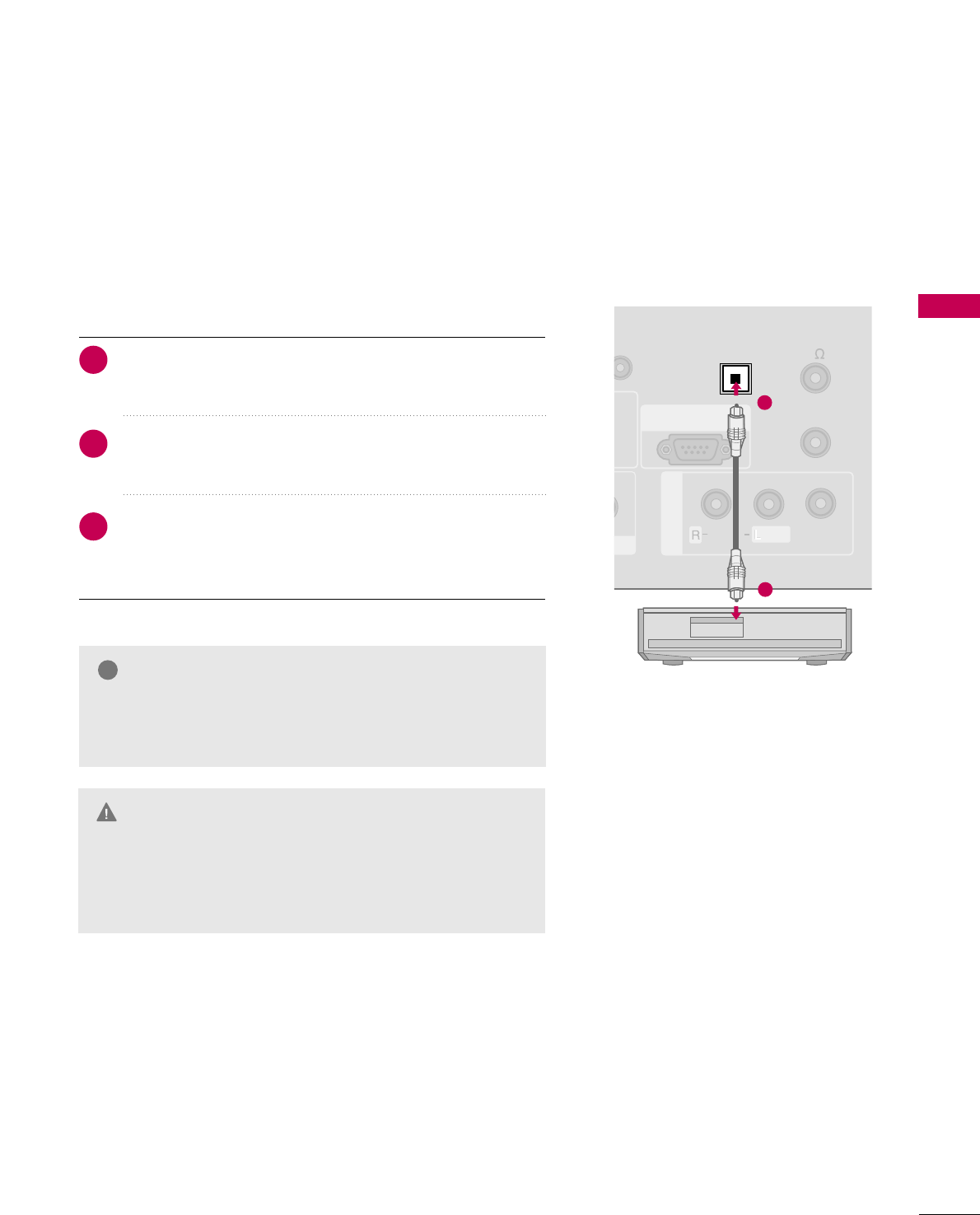
Connect one end of the optical or coaxial cable to the
TV’s OOPPTTIICCAALL port of DDIIGGIITTAALL AAUUDDIIOO OOUUTT.
Connect the other end of the optical or coaxial cable to
the digital audio input on the audio equipment.
Set the “TV Speaker option - Off” in the AUDIO menu. (GG
pp..9933). See the external audio equipment instruction manu-
al for operation.
EXTERNAL EQUIPMENT SETUP
33
AUDIO OUT CONNECTION
Send the TV’s audio to external audio equipment via the Audio Output port.
REMOTE
CONTROL OUT
OPTICAL
DIGITAL
AUDIO OUT
AV IN 1
AUDIO
VIDEO
MONO
/
UPDATE
O
VI)
SPEAKER OUT
8
RS-232C IN
(SERVICE ONLY)
OPTICAL
DIGITAL
AUDIO OUT
1
2
GGWhen connecting with external audio equipments, such as
amplifiers or speakers, you can turn the TV speakers off in
the menu. (GG pp..6611)
NOTE
!
GDo not look into the optical output port. Looking at the
laser beam may damage your vision.
GGBlock the SPDIF out (optical/coaxial) about the contents
with ACP(Audio Copy Protection) function.
CAUTION
1. How to connect
2
3
1
Digital
WATCHING TV / CHANNEL CONTROL
34
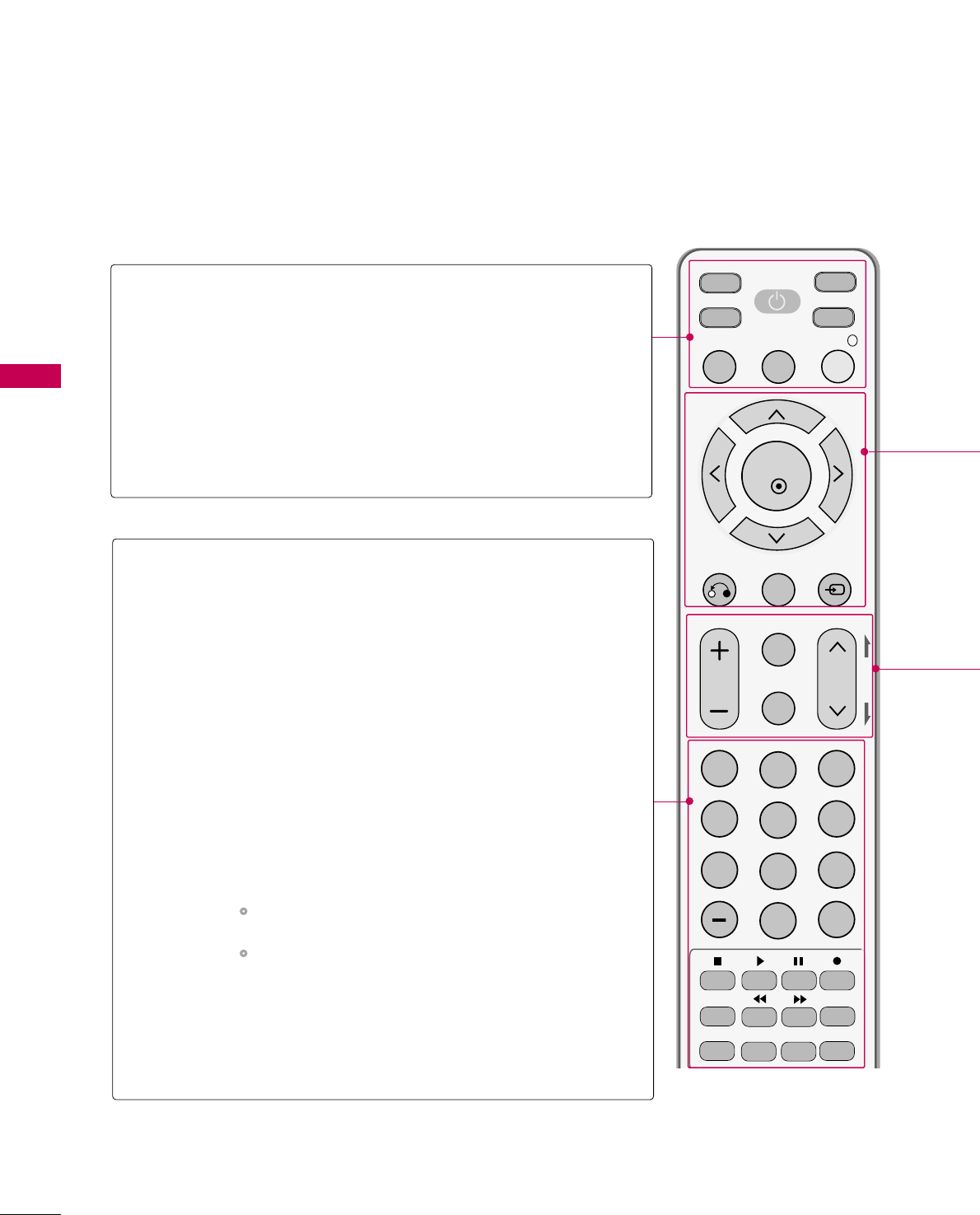
REMOTE CONTROL FUNCTIONS
WATCHING TV / CHANNEL CONTROL
When using the remote control, aim it at the remote control sensor on the TV.
MUTE
RETURN
CC
TV
POWER
GUIDE
PORTAL
ENTER
VOL CH
123
456
78
0
9
FLASHBK
VCR
DVD
INPUT
MENU
INFO
i
STB
P
A
G
E
PIP SAP
PIP CH- PIP CH+
PIP SWAP
PIP INPUT
ALPHA/NUM
REMOVE
RATIO
TIMER
POWER
TV/STB/DVD/VCR
GUIDE
PORTAL
INFO
Turns your TV or any other programmed equipment on
or off, depending on mode.
Select the remote’s operating mode: TV, STB, DVD, or
VCR.
Displays and removes electronic channel guide.
Displays and removes hotel interactive menu.
Display information at the top of the screen.
NUMBER
button
— (DASH)
FLASH BACK
VCR/DVD
control buttons
PIP
RATIO
TIMER
SAP
PIP CH +/-
PIP SWAP
PIP INPUT
Navigate the on-screen menus and adjust the system set-
tings to your preference.
Used to enter a program number for multiple program
channels such as 2-1, 2-2, etc.
Tune to the last channel viewed.
Control video cassette recorders or DVD players.
Switches the sub picture Double Window or off mode.
Change the aspect ratio. GGpp..4444
Select the amount of time before your TV turns off auto-
matically. GGpp..7722
Analog mode: Selects MTS sound (Mono, Stereo, or a
SAP) GGpp..6633
DTV mode: Changes the audio language.
Changes the PIP channel.
Exchange the main/sub images.
Select the connected input source for the sub-picture.
WATCHING TV / CHANNEL CONTROL
35
Installing Batteries
■
Open the battery compartment cover on the back side and install
the batteries matching correct polarity (+with +,-with -).
■
Install two 1.5V AAA batteries. Don’t mix old or used batteries with
new ones.
■
Close cover.
THUMBSTICK
(Up/Down/Left
Right/ENTER)
RETURN
MENU
INPUT
Navigate the on-screen menus and adjust the system settings to your preference.
Clears all on-screen displays and returns to TV viewing from any menu.
Displays the main menu.
External input modes rotate in regular sequence: TV, AV1-2, Component, RGB-PC,
HDMI1 and HDMI2.
VOLUME UP
/DOWN
CC
MUTE
CHANNEL
UP/DOWN
PAGE
UP/DOWN
Increase/decrease the sound level.
Select a closed caption. GGpp..6666
Switch the sound on or off. GGpp..3377
Select available channels.
Move from one full set of screen information to the next one.
WATCHING TV / CHANNEL CONTROL
36
WATCHING TV / CHANNEL CONTROL
TURNING ON TV
WATCHING TV / CHANNEL CONTROL
NOTE
!
GGIf you intend to be away on vacation, disconnect the power plug from the wall power outlet.
First, connect power cord correctly.
At this moment, the TV switches to standby mode.
■In standby mode to turn TV on, press the button on the TV or press
the PPOOWWEERRbutton on the remote control.
Select the viewing source by using the IINNPPUUTTbutton on the remote control.
■This TV is programmed to remember which power state it was last set to,
even if the power cord is out.
When finished using the TV, press the PPOOWWEERRbutton on the remote control.
The TV reverts to standby mode.
1
2
3
WATCHING TV / CHANNEL CONTROL
37
Press the CCHH((or ))or NNUUMMBBEERRbuttons to select a channel number.
1
VOLUME ADJUSTMENT
CHANNEL SELECTION
Press the VVOOLL((++ or --))button to adjust the volume.
If you want to switch the sound off, press the MMUUTTEEbutton.
You can cancel the Mute function by pressing the MMUUTTEEor VVOOLL((++ or --))
button.
Adjust the volume to suit your personal preference.
1
2
3
WATCHING TV / CHANNEL CONTROL
38
WATCHING TV / CHANNEL CONTROL
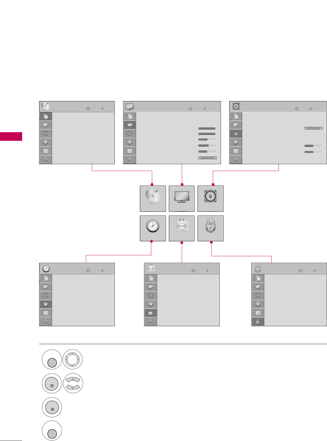
ON-SCREEN MENUS SELECTION
Your TV's OSD (On Screen Display) may differ slightly from that shown in this manual.
Display each menu.
Select a menu item.
Enter to the pop up menu.
1
MENU
3
2
ENTER
ENTER
Return to TV viewing.
4
MENU
Enter
Move
CHANNEL
CHANNEL
TIME
PICTURE
OPTION
AUDIO
LOCK
Enter
Move
Aspect Ratio : 16:9
Picture Mode : Standard
• Back Light 80
• Contrast 90
• Brightness 50
• Sharpness 60
• Color 60
• Tint 0
PICTURE
E
Enter
Move
Auto Volume : Off
Clear Voice : On
Balance 0
Sound Mode : Standard
•
SRS TruSurround XT:
Off
• Treble 50
• Bass 50
• Reset
AUDIO
E
LR
Enter
Move
Clock :
Feb/21/2008/ 2:10 AM
Off Time : Off
On Time : Off
Sleep Timer : Off
Auto Sleep : Off
TIME
Enter
Move
Lock System : Off
Set Password
Block Channel
Movie Rating
TV Rating-Children
TV Rating-General
Downloadable Rating
Input Block
LOCK
RG
Auto Tuning
Manual Tuning
Channel Edit
Channel Label
Data Broadcasting
Enter
Move
Language : English
Caption : Off
OPTION
WATCHING TV / CHANNEL CONTROL
39
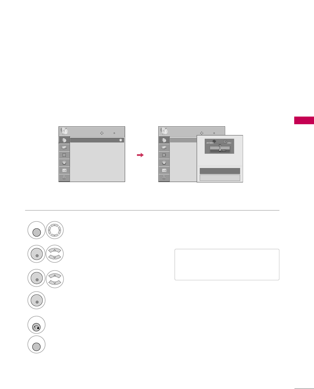
CHANNEL SETUP
Auto Scan (Auto Tuning)
Automatically finds all channels available through antenna or cable inputs, and stores them in memory on the
channel list.
Run Auto Tuning again after any Antenna/Cable connection changes.
Select CCHHAANNNNEELL.
Select AAuuttoo TTuunniinngg.
Select YYeess.
Run AAuuttoo ttuunniinngg.
1
MENU
3
2
ENTER
ENTER
4
ENTER
■A password is required to gain access to
Auto Tuning menu if the Lock System is
turned on.
5
RETURN
Return to the previous menu.
MENU
Return to TV viewing.
Enter
Move
CHANNEL
Auto Tuning
Manual Tuning
Channel Edit
Channel Label
Data Broadcasting
Enter
Move
CHANNEL
Auto Tuning
Manual Tuning
Channel Edit
Channel Label
Data Broadcasting
Press ‘Yes’ button to begin
auto tuning.
Yes
No
WATCHING TV / CHANNEL CONTROL
40
WATCHING TV / CHANNEL CONTROL
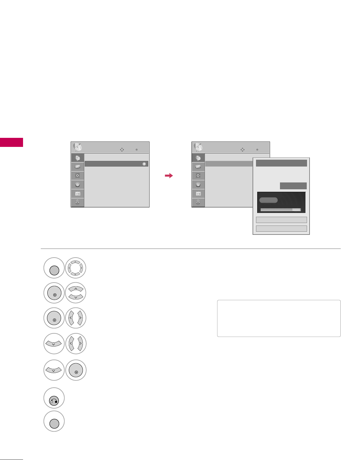
Select CCHHAANNNNEELL.
1
MENU
2
ENTER
If selecting DTV or CADTV input signal, you can view the on-screen signal strength monitor to see the quality
of the signal being received.
Add/Delete Channel (Manual Tuning)
Select MMaannuuaall TTuunniinngg.
Select DDIIGGIITTAALLor AANNAALLOOGG.
Select channel you want to add
or delete.
3
ENTER
4
Select AAdddd or DDeelleettee.
5
ENTER
■A password is required to gain access to
Manual Tuning menu if the Lock System
is turned on.
6
RETURN
Return to the previous menu.
MENU
Return to TV viewing.
Enter
Move
CHANNEL
Enter
Move
CHANNEL
Auto Tuning
Manual Tuning
Channel Edit
Channel Label
Data Broadcasting
Channel
Select channel type and
RF-channel number.
FF
DIGITAL
GG
FF2GG
Close
Delete
DIGITAL 2-1
Bad Normal Good
Auto Tuning
Manual Tuning
Channel Edit
Channel Label
Data Broadcasting
WATCHING TV / CHANNEL CONTROL
41
Select a channel.
Select channel you want to add or delete.
3
ENTER
4
ENTER
A custom list can be created by toggling each channel on or off with ENTER button. The channels in the Custom
List are displayed in black and the channels deleted from the Custom List are displayed in gray.
Once a channel is highlighted you can add or delete the channel by referring to the small window at the top-
right corner of the screen.
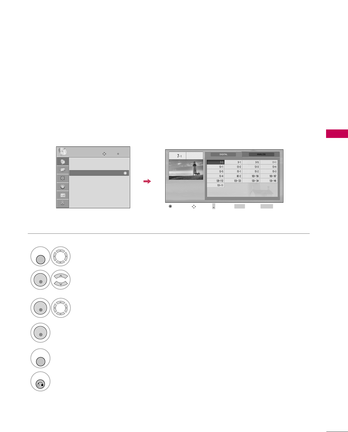
Channel Editing
Select CCHHAANNNNEELL.
1
MENU
2
ENTER
Select CChhaannnneell EEddiitt.
RETURN
Return to TV viewing.
Return to the previous menu.
5
MENU
Add/Delete Move Page
CH
Move Previous RETURN EXIT
MENU
Enter
Move
CHANNEL
Auto Tuning
Manual Tuning
Channel Edit
Channel Label
Data Broadcasting
+
WATCHING TV / CHANNEL CONTROL
42
WATCHING TV / CHANNEL CONTROL
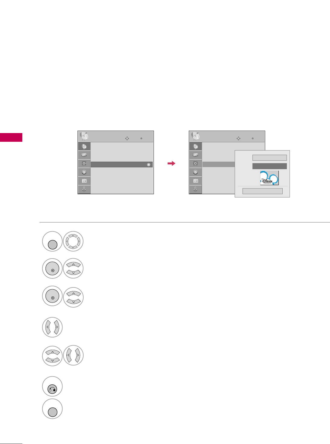
CHANNEL LABEL
Choose preset labels for your channels.
If a channel label is provided on the signal from the broadcasting station, the TV displays a short name for a
channel even if you didn't preset a label for the channel.
Enter
Move
CHANNEL
Auto Tuning
Manual Tuning
Channel Edit
Channel Label
Data Broadcasting
Enter
Move
CHANNEL
Auto Tuning
Manual Tuning
Channel Edit
Channel Label
Data Broadcasting
Logo FF Disney GG
Channel DIGITAL 2-1
Close
Select CCHHAANNNNEELL.
Select CChhaannnneell LLaabbeell.
Select Channel.
1
MENU
3
2
ENTER
ENTER
Select the appropriate logo for the channel.
5
Select a channel to set logo.
4
6
RETURN
Return to the previous menu.
MENU
Return to TV viewing.

WATCHING TV / CHANNEL CONTROL
43
INPUT LIST
Select the desired input source.
1
INPUT
TV AV1 AV2
ComponentHDMI1 RGB-PC
TV AV1 AV2 Component RGB-PC
ENTER
■TTVV: Select it to watch over-the-air, cable
and digital cable broadcasts.
■AAVV11--22: Select them to watch a VCR or
other external equipment.
■CCoommppoonneenntt: Select them to watch
DVD or a Digital set-top box.
■RRGGBB--PPCC: Select it to view PC input.
■HHDDMMII11--22: Select them to watch high
definition devices.
HDMI2
PICTURE CONTROL
44
PICTURE SIZE (ASPECT RATIO) CONTROL
PICTURE CONTROL
This feature lets you choose the way an analog picture with a 4:3 aspect ratio is displayed on your TV.
■ RGB-PC input source use 4:3 or 16:9 aspect ratio.
NOTE
!
GGIf a fixed image is displayed on the screen for a long time, the image could become imprinted on the
screen and remain visible.
This phenomenon is rare on LCDs, but is possible when the image is on the screen for a very long time.
This phenomenon is common to all manufacturers and is not covered by warranty. When watching video
that does not fill the screen, any after-image from the black bars will normally dissipate after a few min-
utes.
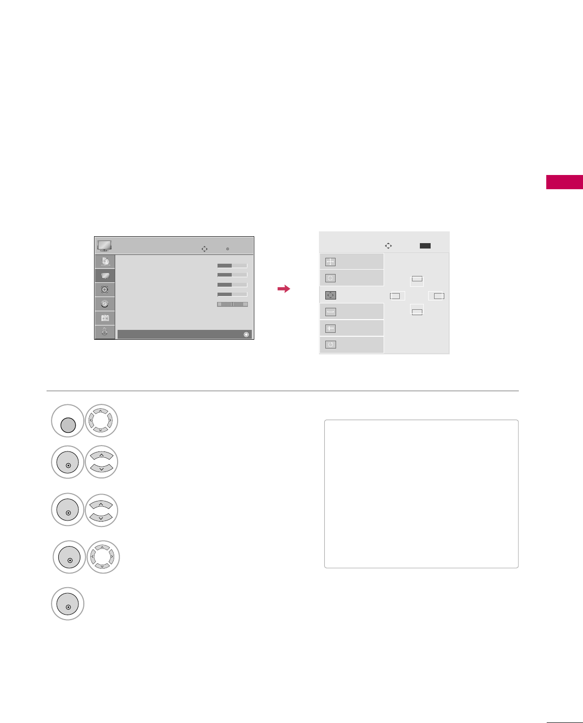
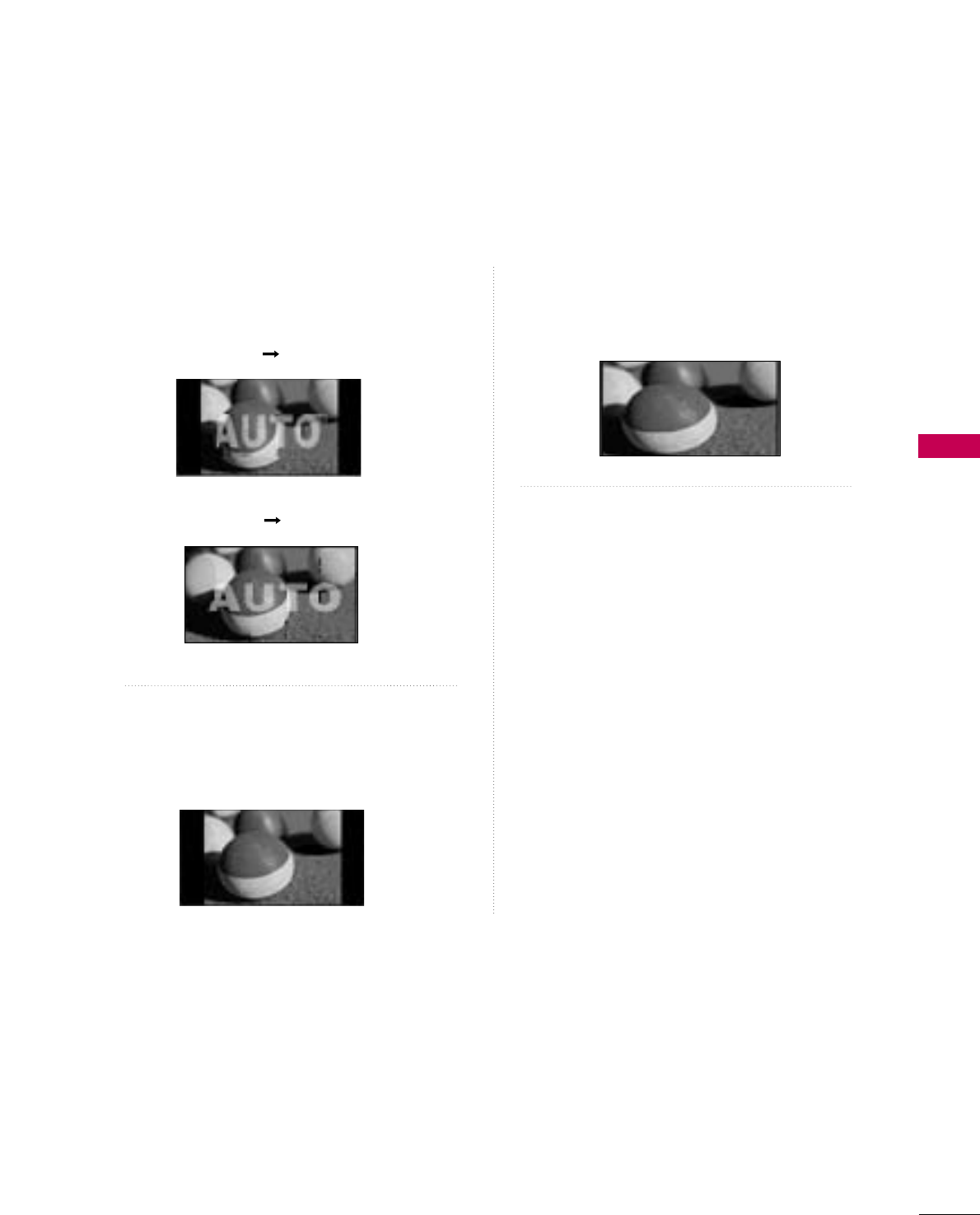
Press the RRAATTIIOObutton repeatedly to select the picture options
: SSeett BByy PPrrooggrraamm,, 44::33,, 1166::99,, ZZoooomm11,, ZZoooomm22,, JJuusstt SSccaann.
1
RATIO
2
RETURN
Return to TV viewing.
1166::99
■ You can also adjust AAssppeecctt RRaattiiooin
the PPIICCTTUURREEmenu.
PICTURE CONTROL
45
Set by program
Selects the proper picture proportion to match
the source’s image.
4:3
Choose 4:3 when you want to view a picture
with an original 4:3 aspect ratio.
16 : 9
Adjust the picture horizontally, in a linear pro-
portion to fill the entire screen.
(4:3 4:3)
(16:9 16:9)
PICTURE CONTROL
46
PICTURE CONTROL
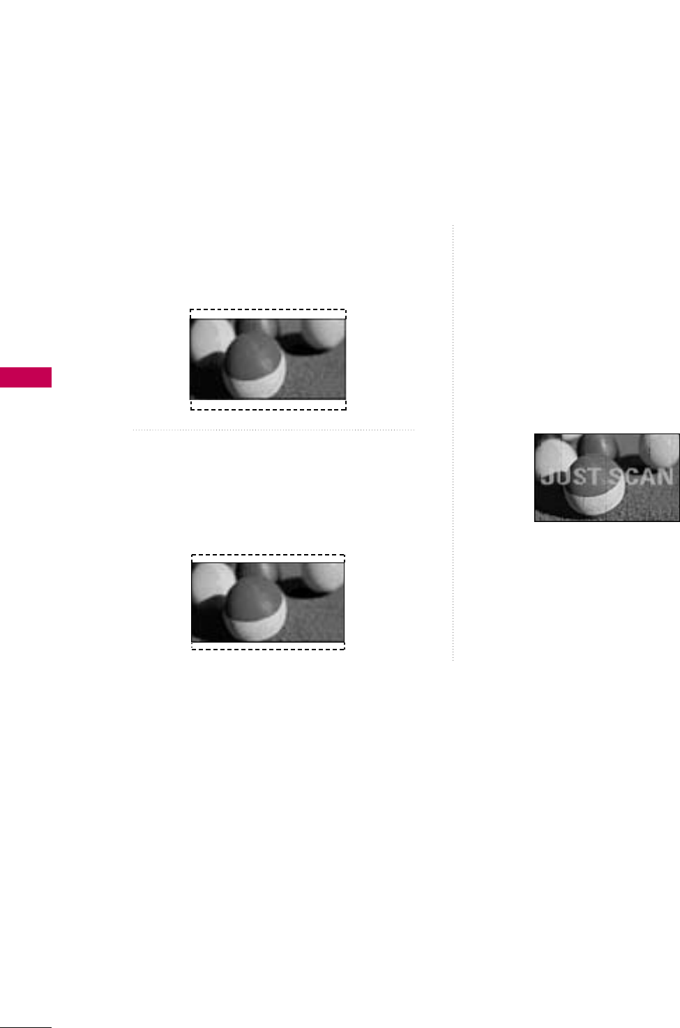
Zoom 1
Choose Zoom 1 when you want to view the pic-
ture without any alteration. However, the top and
bottom portions of the picture will be cropped.
Zoom 2
Choose Zoom 2 when you want the picture to be
altered, both vertically extended and cropped.
The picture taking a halfway trade off between
alteration and screen coverage.
Just Scan
Normally the edges of video signals are cropped
1-2%. Just Scan turns off this cropping and
shows the complete video.
Notes: If there is noise on the edges of the original
signal, it will be visible when Just Scan is activated.
JJuusstt SSccaannoperates only with
DTV/CADTV/HDMI-DTV/DVI-DTV
(720p/1080i/1080p),
Component(720p/1080i) input sources.
PICTURE CONTROL
47
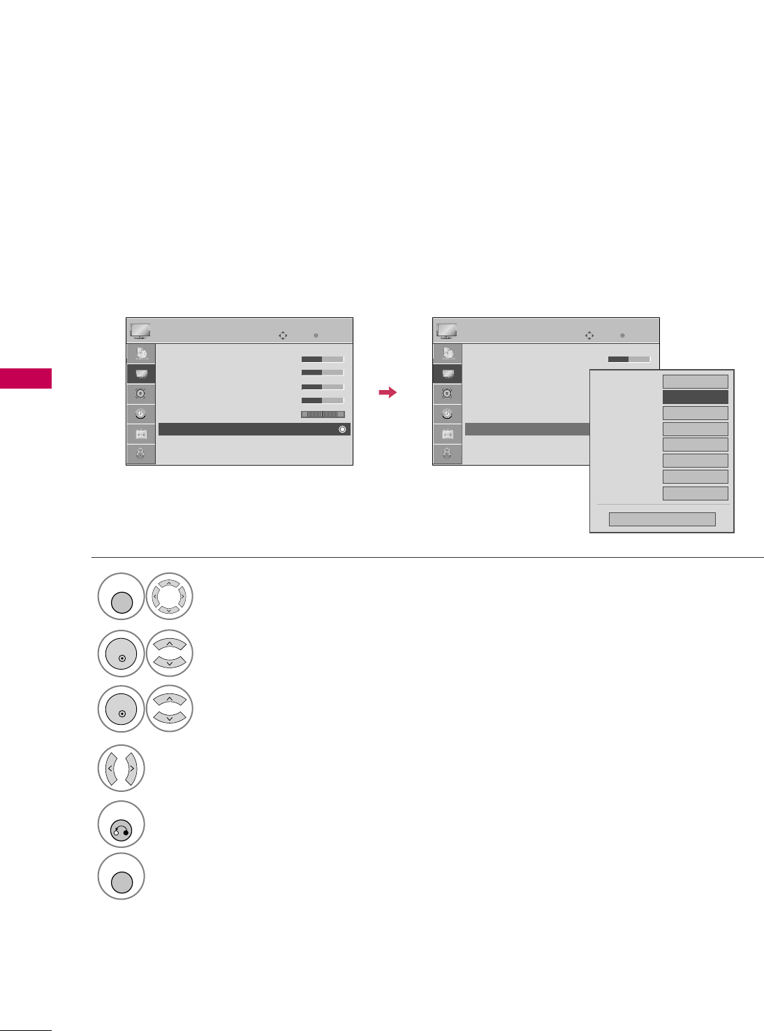
PRESET PICTURE SETTINGS
Picture Mode - Preset
There are factory presets for picture settings available in the user menus. You can use a preset, change each
setting manually.
Enter
Move
PICTURE
E
Aspect Ratio : 16:9
Picture Mode : Standard
• Back Light 90
• Contrast 90
• Brightness 50
• Sharpness 60
• Color 60
• Tint 0 RG
Enter
Move
PICTURE
E
Aspect Ratio : 16:9
Picture Mode : Standard
• Back Light 90
• Contrast 90
• Brightness 50
• Sharpness 60
• Color 60
• Tint 0 RG
Intelligent Sensor
Vivid
Standard
Cinema
Sport
Game
Select PPIICCTTUURREE.
Select IInntteelllliiggeenntt SSeennssoorr, VViivviidd,
SSttaannddaarrdd, CCiinneemmaa, SSppoorrttor GGaammee.
1
MENU
3
ENTER
Select PPiiccttuurree MMooddee.
2
ENTER
4
RETURN
Return to the previous menu.
MENU
Return to TV viewing.
■When selecting IInntteelllliiggeenntt SSeennssoorr,
the most suitable picture is automatically
adjusted according to the surrounding
conditions.
■VViivviidd, SSttaannddaarrdd, CCiinneemmaa, SSppoorrtt, and
GGaammeeSettings are preset for the opti-
mum picture quality at the factory and
are not adjustable.
PICTURE CONTROL
48
PICTURE CONTROL
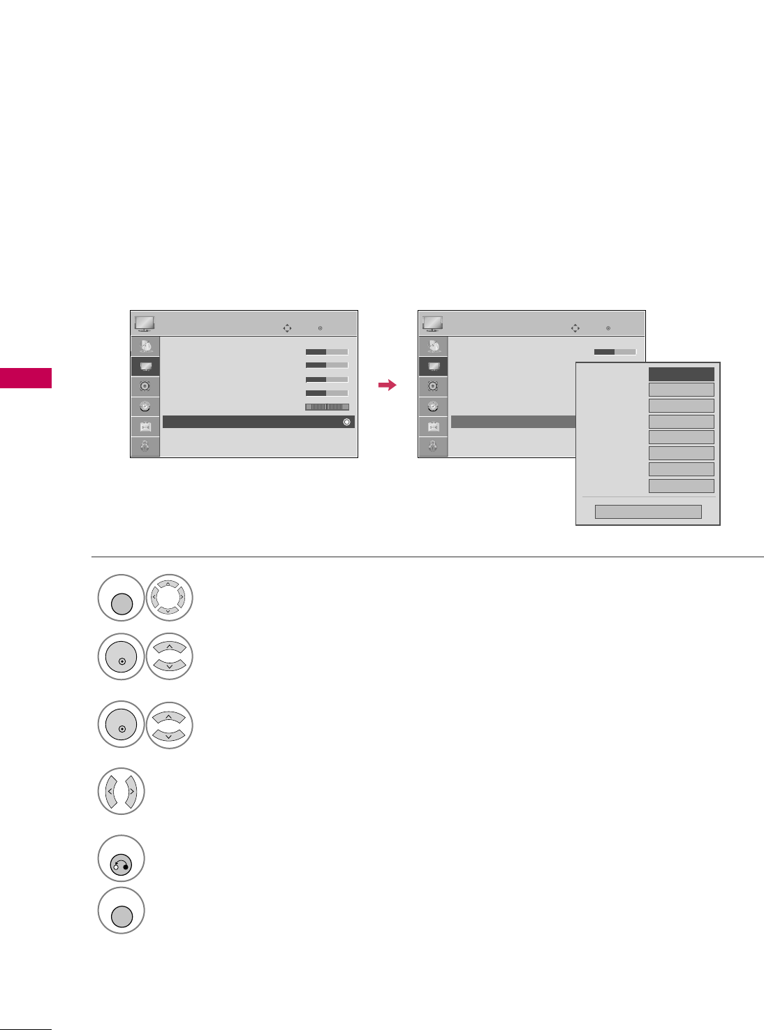
Color Tone - Preset
Choose one of three automatic color adjustments. Set to warm to enhance hotter colors such as red, or set to
cool to see less intense colors with more blue.
Select PPIICCTTUURREE.
Select CCoolloorr TTeemmppeerraattuurree.
1
MENU
3
ENTER
Select CCooooll, MMeeddiiuumm, or WWaarrmm.
4
Select AAddvvaanncceedd CCoonnttrrooll.
2
ENTER
5
RETURN
Return to the previous menu.
MENU
Return to TV viewing.
Enter
Move
PICTURE
EE
RG
• Contrast 50
• Brightness 50
• Sharpness 50
• Color 50
• Tint 0
• Advanced Control
• Reset
Screen (RGB-PC)
Enter
Move
PICTURE
E
RG
• Contrast 50
• Brightness 50
• Sharpness 50
• Color 50
• Tint 0
• Advanced Control
• Reset
Screen (RGB-PC)
Color Temperature
FFMedium GG
Fresh Contrast
Off
Fresh Color
Off
Noise Reduction
Auto
Gamma
Medium
Black Level
Medium
Eye Care
Off
Close
Film Mode
Off
PICTURE CONTROL
49
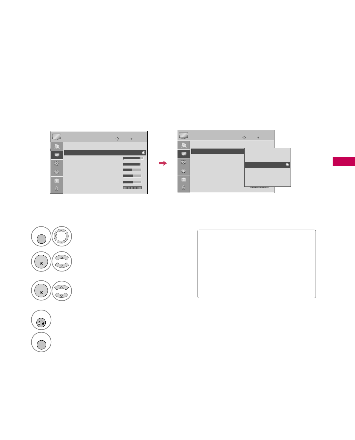
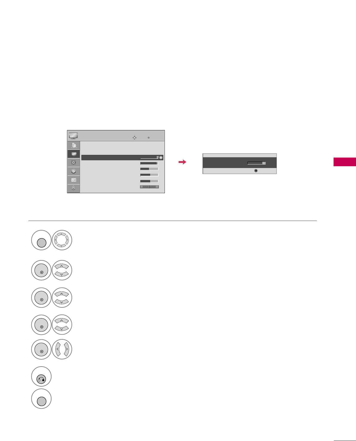
MANUAL PICTURE ADJUSTMENT
Picture Mode - User Mode
Adjust the picture appearance to suit your preference and viewing situations.
This feature is disable in “PPiiccttuurree MMooddee--IInntteelllliiggeenntt SSeennssoorr”.
Select PPIICCTTUURREE.
Make appropriate adjustments.
Select BBaacckk LLiigghhtt,, CCoonnttrraasstt,, BBrriigghhttnneessss,,
SShhaarrppnneessss,, CCoolloorr,, or TTiinntt..
1
MENU
Select PPiiccttuurree MMooddee.
2
ENTER
Select VViivviidd,SSttaannddaarrdd, CCiinneemmaa, SSppoorrttor GGaammee.
3
ENTER
4
ENTER
5
ENTER
6
RETURN
Return to the previous menu.
Return to TV viewing.
• Back Light 80
EE
EE
EE
EE
Enter
Enter
Move
PICTURE
E
Aspect Ratio : 16:9
Picture Mode : Standard (User)
• Back Light 90
• Contrast 90
• Brightness 50
• Sharpness 60
• Color 60
• Tint 0 RG
MENU
PICTURE CONTROL
50
PICTURE CONTROL
PICTURE IMPROVEMENT TECHNOLOGY
Fresh Contrast: Optimizes the contrast automatically according to the brightness of the reflection.
Fresh Color: Adjusts the color of the reflection automatically to reproduce as close as possible natural colors.
Noise Reduction: Removes interference up to the point where it does not damage the original picture.
Gamma: High gamma values display whitish images and low gamma values display high contrast images.
Select PPIICCTTUURREE.
Select AAddvvaanncceedd CCoonnttrrooll.
Select FFrreesshh CCoonnttrraasstt, FFrreesshh CCoolloorr,
NNooiissee RReedduuccttiioonn, or GGaammmmaa.
1
MENU
3
2
ENTER
ENTER
5
RETURN
Return to the previous menu.
Return to TV viewing.
Select your desired options.
4
Enter
Move
PICTURE
E
RG
• Contrast 50
• Brightness 50
• Sharpness 50
• Color 50
• Tint 0
• Advanced Control
• Reset
Screen (RGB-PC)
MENU
Enter
Move
PICTURE
EE
RG
• Contrast 50
• Brightness 50
• Sharpness 50
• Color 50
• Tint 0
• Advanced Control
• Reset
Screen (RGB-PC)
Color Temperature
Medium
Fresh Contrast
FF Off GG
Fresh Color
Off
Noise Reduction
Auto
Gamma
Medium
Black Level
Medium
Eye Care
Off
Close
Film Mode
Off