LG Electronics USA 37LH260HUA LCD TV MONITOR User Manual EMISSION TEST REPORT
LG Electronics USA LCD TV MONITOR EMISSION TEST REPORT
Users Manual

Order Number : GETEC-C1-09-207 FCC Class B Certification
Test Report Number : GETEC-E3-09-120 Page 1 / 1
EUT Type: LCD TV/Monitor
APPENDIX G
: USER’S MANUAL
FCC ID.: BEJ37LH260HUA

LCD TV
OWNER’S MANUAL
32LH240H
32LH250H
37LH250H
32LH255H
37LH255H
42LH255H
37LH260H
42LH260H
P/NO : SAC34026002 (0908-REV02)
www.lgcommercial.com
This product qualifies for ENERGY STAR in the “factory default
(Home Use)” setting.
Changing the factory default settings or enabling other fea-
tures may increase power consumption that could exceed the
limits necessary to quality for ENERGY STAR.
1-800-243-0000 USA, Consumer User
1-888-865-3026 USA, Commercial User
1-888-542-2623 CANADA
LG Customer Information Center
Model:
Serial:
please read this manual carefully before operating
your set.
Retain it for future reference.
Record model number and serial number of the set.
See the label attched on the back cover and quote
this information to your dealer
when you require service.

1
WARNING / CAUTION
WARNING / CAUTION
To prevent fire or shock hazards, do not expose
this product to rain or moisture.
FCC NOTICE
Class B digital device
This equipment has been tested and found to comply
with the limits for a Class B digital device, pursuant to
Part 15 of the FCC Rules. These limits are designed
to provide reasonable protection against harmful
interference in a residential installation. This equipment
generates, uses and can radiate radio frequency energy
and, if not installed and used in accordance with the
instructions, may cause harmful interference to radio
communications. However, there is no guarantee that
interference will not occur in a particular installation.
If this equipment does cause harmful interference to
radio or television reception, which can be determined
by turning the equipment off and on, the user is
encouraged to try to correct the interference by one
or more of the following measures:
- Reorient or relocate the receiving antenna.
- Increase the separation between the equipment and
receiver.
- Connect the equipment to an outlet on a circuit
different from that to which the receiver is connected.
- Consult the dealer or an experienced radio/TV
technician for help.
This device complies with part 15 of the FCC Rules.
Operation is subject to the following two condi-
tions: (1) This device may not cause (harmful)
interference, and (2) this device must accept any
interference received, including interference that
may cause undesired operation (of the device).
Any changes or modifications in construction of this
device which are not expressly approved by the party
responsible for compliance could void the user’s
authority to operate the equipment.
CAUTION
Do not attempt to modify this product in any way
without written authorization from LG Electronics.
Unauthorized modification could void the user’s
authority to operate this product
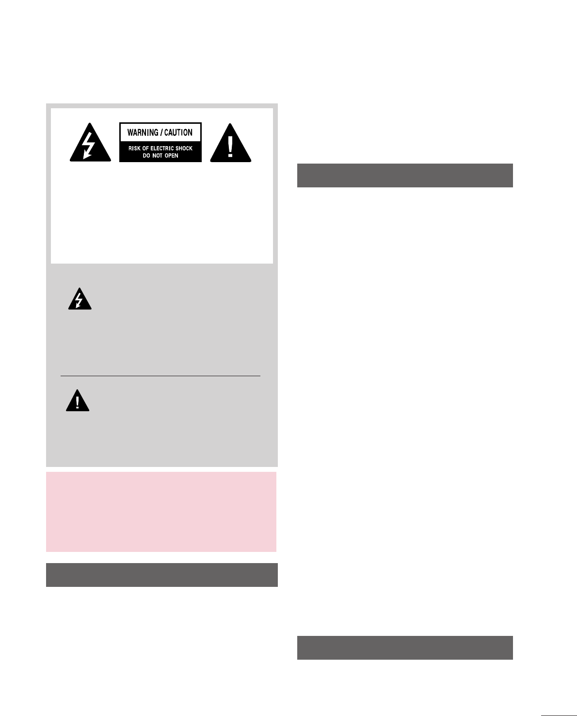
The lightning flash with arrowhead
symbol, within an equilateral triangle, is
intended to alert the user to the presence
of uninsulated “dangerous voltage” within the
product’s enclosure that may be of sufficient
magnitude to constitute a risk of electric shock to
persons.
The exclamation point within an equilateral
triangle is intended to alert the user to
the presence of important operating
and maintenance (servicing) instructions in the
literature accompanying the appliance.
TO REDUCE THE RISK OF ELECTRIC SHOCK
DO NOT REMOVE COVER (OR BACK). NO
USER SERVICEABLE PARTS INSIDE. REFER TO
QUALIFIED SERVICE PERSONNEL.
WARNING/CAUTION
TO REDUCE THE RISK OF FIRE AND ELECTRIC
SHOCK, DO NOT EXPOSE THIS PRODUCT TO
RAIN OR MOISTURE.
NOTE TO CABLE/TV INSTALLER
This reminder is provided to call the CATV system
installer’s attention to Article 820-40 of the National
Electric Code (U.S.A.). The code provides guidelines for
proper grounding and, in particular, specifies that the
cable ground shall be connected to the grounding system
of the building, as close to the point of the cable entry
as practical.
Read these instructions.
Keep these instructions.
Heed all warnings.
Follow all instructions.
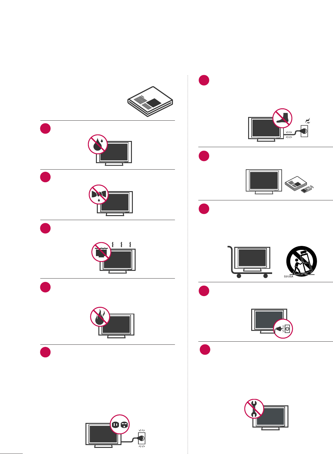
Do not use this apparatus near water.
Clean only with dry cloth.
Do not block any ventilation openings. Install in
accordance with the manufacturer’s instructions.
Do not install near any heat sources such as
radiators, heat registers, stoves, or other apparatus
(including amplifiers)that produce heat.
Do not defeat the safety purpose of the polarized
or grounding-type plug. A polarized plug has
two blades with one wider than the other. A
grounding type plug has two blades and a third
grounding prong, The wide blade or the third
prong are provided for your safety. If the provided
plug does not fit into your outlet, consult an
electrician for replacement of the obsolete outlet.
Protect the power cord from being walked on
or pinched particularly at plugs, convenience
receptacles, and the point where they exit from
the apparatus.
Only use attachments/accessories specified by
the manufacturer.
Use only with the cart, stand, tripod, bracket,
or table specified by the manufacturer, or sold
with the apparatus. When a cart is used, use
caution when moving the cart/apparatus
combination to avoid injury from tip-over.
Unplug this apparatus during lighting storms or
when unused for long periods of time.
Refer all servicing to qualified service personnel.
Servicing is required when the apparatus has been
damaged in any way, such as power-supply cord or
plug is damaged, liquid has been spilled or objects
have fallen into the apparatus, the apparatus has
been exposed to rain or moisture, does not operate
normally, or has been dropped.
2
IMPORTANT SAFETY INSTRUCTIONS
SAFETY INSTRUCTIONS
1
2
3
4
5
7
8
6
9
10
3
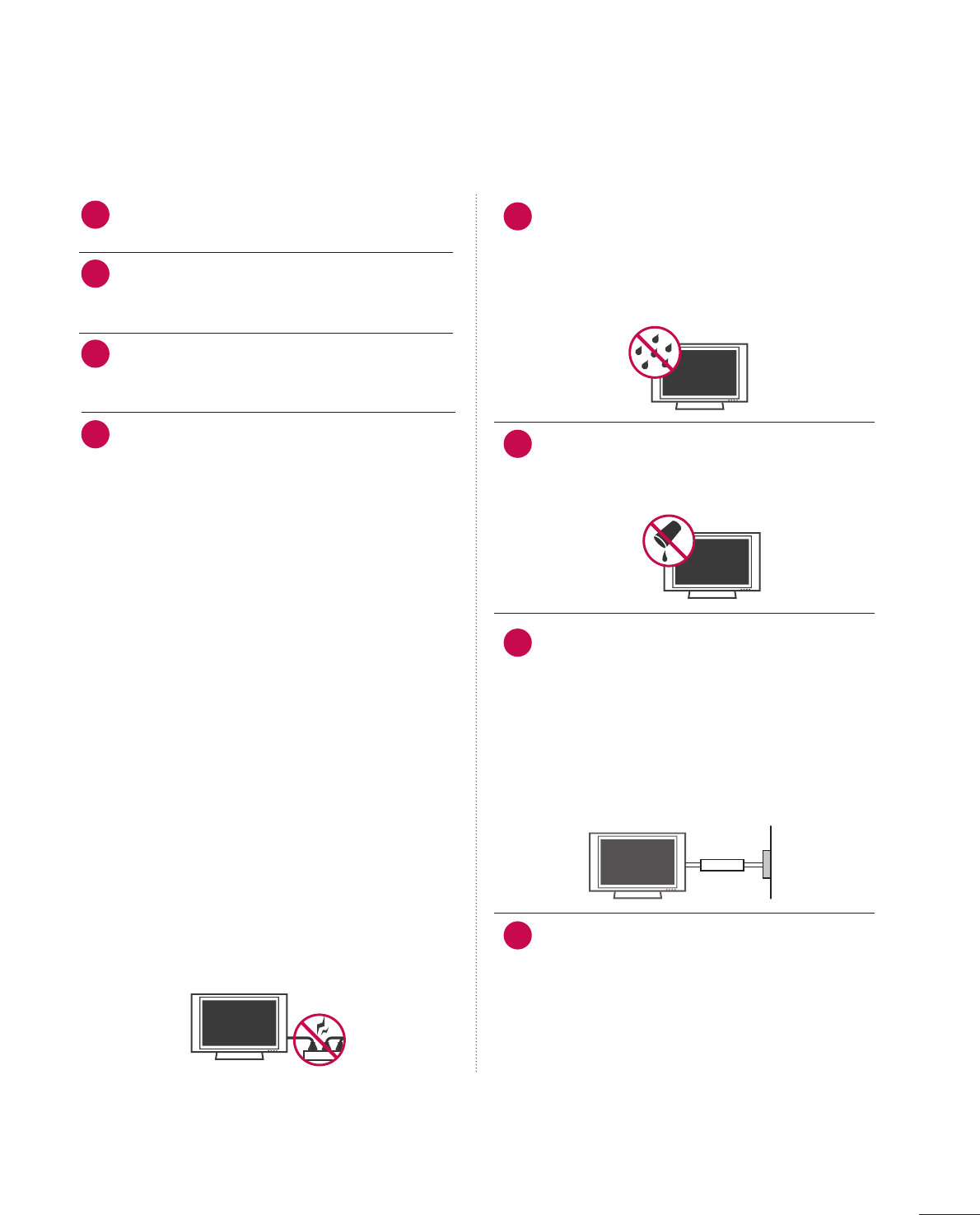
Never touch this apparatus or antenna during a
thunder or lighting storm.
When mounting a TV on the wall, make sure not to
install the TV by the hanging power and signal
cables on the back of the TV.
Do not allow an impact shock or any objects to fall
into the product, and do not drop onto the screen
with something.
CAUTION concerning the Power Cord :
It is recommend that appliances be placed upon a
dedicated circuit; that is, a single outlet circuit which
powers only that appliance and has no additional
outlets or branch circuits. Check the specification
page of this owner's manual to be certain.
Do not connect too many appliances to the same
AC power outlet as this could result in fire or elec-
tric shock.
Do not overload wall outlets. Overloaded wall out-
lets, loose or damaged wall outlets, extension cords,
frayed power cords, or damaged or cracked wire
insulation are dangerous. Any of these conditions
could result in electric shock or fire. Periodically
examine the cord of your appliance, and if its
appearance indicates damage or deterioration,
unplug it, discontinue use of the appliance, and
have the cord replaced with an exact replacement
part by an authorized servicer. Protect the power
cord from physical or mechanical abuse, such as
being twisted, kinked, pinched, closed in a door, or
walked upon. Pay particular attention to plugs, wall
outlets, and the point where the cord exits the
appliance.
Do not make the TV with the power cord plugged
in. Do not use a damaged or loose power cord. Be
sure do grasp the plug when unplugging the power
cord. Do not pull on the power cord to unplug the
TV.
WARNING - To reduce the risk of fire or electrical
shock, do not expose this product to rain, moisture
or other liquids. Do not touch the TV with wet
hands. Do not install this product near flammable
objects such as gasoline or candles or expose the
TV to direct air conditioning.
Do not expose to dripping or splashing and do not
place objects filled with liquids, such as vases, cups,
etc. on or over the apparatus (e.g. on shelves above
the unit).
GGRROOUUNNDDIINNGG
Ensure that you connect the earth ground wire to
prevent possible electric shock. (i.e. a TV with a
three-prong grounded AC plug must be connected
to a three-prong grouned AC outlet) If grounding
methods are not possible, have a qualified electri-
cian install a separate circuit breaker.
Do not try to ground the unit by connecting it to
telephone wires, lightening rods, or gas pipes.
DDIISSCCOONNNNEECCTTIINNGG DDEEVVIICCEE FFRROOMM MMAAIINNSS
Mains plug is the disconnecting device. The plug
must remain readily operable.
12
11
14
13
16
17
18
Power
Supply
Short-circuit
Breaker
15
4
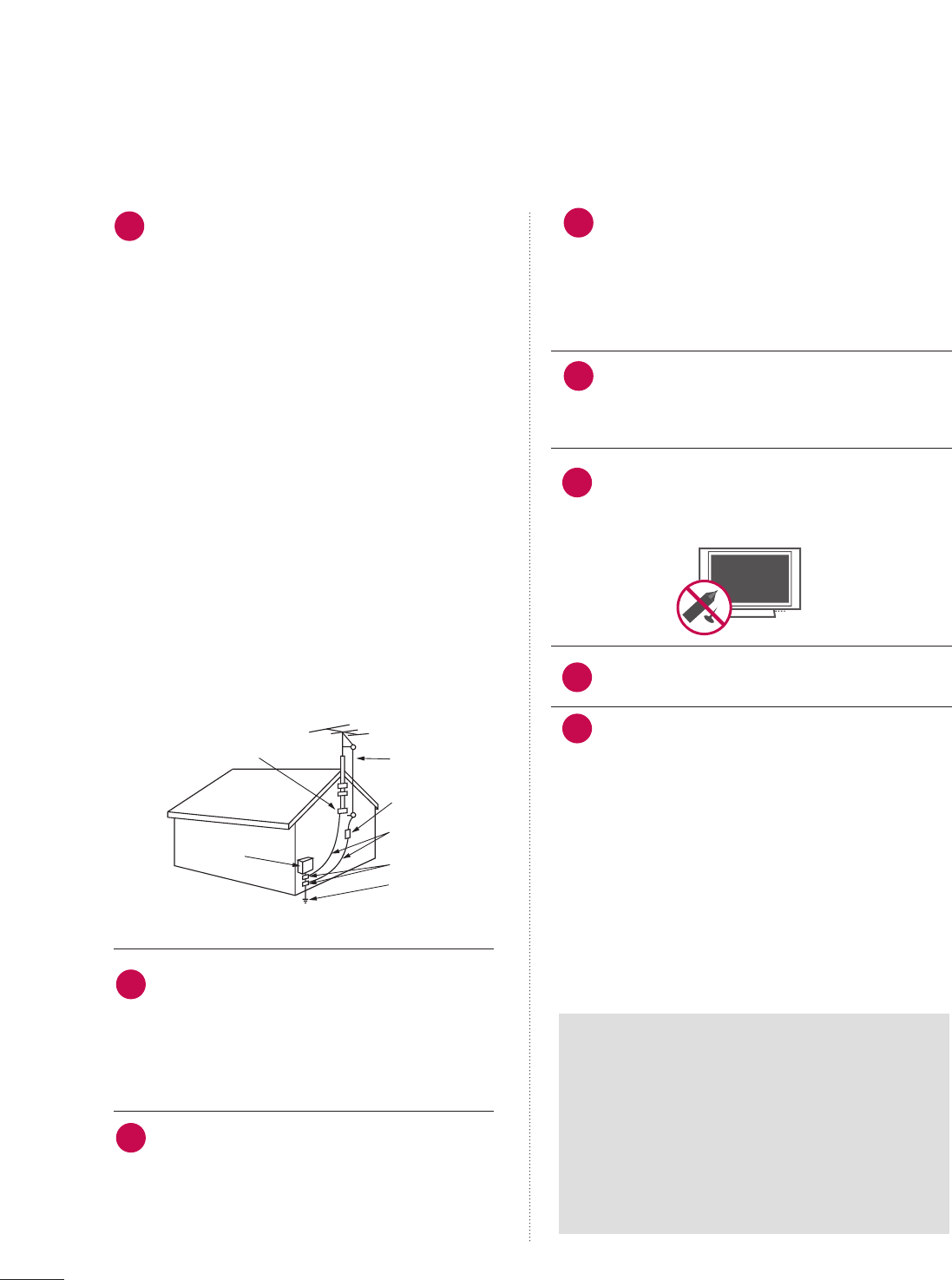
AANNTTEENNNNAASS
OOuuttddoooorr aanntteennnnaa ggrroouunnddiinngg
If an outdoor antenna is installed, follow the precau-
tions below. An outdoor antenna system should not
be located in the vicinity of overhead power lines or
other electric light or power circuits, or where it can
come in contact with such power lines or circuits as
death or serious injury can occur.
Be sure the antenna system is grounded so as to pro-
vide some protection against voltage surges and
built-up static charges.
Section 810 of the National Electrical Code (NEC) in
the U.S.A. provides information with respect to prop-
er grounding of the mast and supporting structure,
grounding of the lead-in wire to an antenna dis-
charge unit, size of grounding conductors, location of
antenna discharge unit, connection to grounding
electrodes and requirements for the grounding elec-
trode.
AAnntteennnnaa ggrroouunnddiinngg aaccccoorrddiinngg ttoo tthhee
NNaattiioonnaall EElleeccttrriiccaall CCoodde
e,, AANNSSII//NNFFPPAA 7700
Cleaning
When cleaning, unplug the power cord and scrub
gently with a soft cloth to prevent scratching. Do not
spray water or other liquids directly on the TV as
electric shock may occur. Do not clean with chemi-
cals such as alcohol, thinners or benzene.
Moving
Make sure the product is turned off, unplugged
and all cables have been removed. It may take 2 or
more people to carry larger TVs. Do not press
against or put stress on the front panel of the TV.
Ventilation
Install your TV where there is proper ventilation. Do
not install in a confined space such as a bookcase.
Do not cover the product with cloth or other mate-
rials (e.g.) plastic while plugged in. Do not install in
excessively dusty places.
If you smell smoke or other odors coming from the
TV or hear strange sounds, unplug the power cord
contact an authorized service center.
Do not press strongly upon the panel with a hand or
sharp object such as nail, pencil or pen, or make a
scratch on it.
Keep the product away from direct sunlight.
FFoorr LLCCDD TTVV
If the TV feels cold to the touch, there may be
a small “flicker” when it is turned on. This is
normal, there is nothing wrong with TV.
Some minute dot defects may be visible on the
screen, appearing as tiny red, green, or blue
spots. However, they have no adverse effect on
the monitor's performance.
Avoid touching the LCD screen or holding your
finger(s) against it for long periods of time.
Doing so may produce some temporary dis-
tortion effects on the screen.
21
19
Antenna Lead in Wire
Antenna Discharge Unit
(NEC Section 810-20)
Grounding Conductors
(NEC Section 810-21)
Ground Clamps
Power Service Grounding
Electrode System (NEC
Art 250, Part H)
Ground Clamp
Electric Service
Equipment
NEC: National Electrical Code
22
23
24
25
20
ON DISPOSAL
(Only Hg lamp used LCD TV)
The fluorescent lamp used in this product contains
a small amount of mercury. Do not dispose of
this product with general household waste.
Disposal of this product must be carried out in
accordance to the regulations of your local authority.
26

5
CONTENTS
WARNING / CAUTION
. . . . . . . . . . . . . . . . . . . . . . . . . . . . 1
SAFETY INSTRUCTIONS
. . . . . . . . . . . . . . . . . . . . . . . . . . 2
FEATURES OF THIS TV
. . . . . . . . . . . . . . . . . . . . . . . . . . . . . 7
PREPARATION
Accessories . . . . . . . . . . . . . . . . . . . . . . . . . . . . . . . . . . . . . . . . . . . . . . . . . . . . . . 8
Front Panel Information . . . . . . . . . . . . . . . . . . . . . . . . . . . . . . . . . . . . . 9
Back Panel Information . . . . . . . . . . . . . . . . . . . . . . . . . . . . . . . . . . . . 10
Stand Instruction . . . . . . . . . . . . . . . . . . . . . . . . . . . . . . . . . . . . . . . . . . . . . 12
VESA Wall Mounting . . . . . . . . . . . . . . . . . . . . . . . . . . . . . . . . . . . . . . . . 14
Cable Management . . . . . . . . . . . . . . . . . . . . . . . . . . . . . . . . . . . . . . . . . 15
Desktop Pedestal Installation . . . . . . . . . . . . . . . . . . . . . . . . . . . . 16
Swivel Stand . . . . . . . . . . . . . . . . . . . . . . . . . . . . . . . . . . . . . . . . . . . . . . . . . . . . 16
Attaching the TV to a desk . . . . . . . . . . . . . . . . . . . . . . . . . . . . . . . 17
Securing the TV to the wall to prevent falling
When the TV is used on a stand
. . . . . . . . . . . . . . . . . . . . . . . . . . 18
Antenna or Cable Connection . . . . . . . . . . . . . . . . . . . . . . . . . . 19
EXTERNAL EQUIPMENT SETUP
HD Receiver Setup . . . . . . . . . . . . . . . . . . . . . . . . . . . . . . . . . . . . . . . . . . 20
DVD Setup . . . . . . . . . . . . . . . . . . . . . . . . . . . . . . . . . . . . . . . . . . . . . . . . . . . . . 23
VCR Setup . . . . . . . . . . . . . . . . . . . . . . . . . . . . . . . . . . . . . . . . . . . . . . . . . . . . . 25
Other A/V Source Setup . . . . . . . . . . . . . . . . . . . . . . . . . . . . . . . . . 26
PC Setup . . . . . . . . . . . . . . . . . . . . . . . . . . . . . . . . . . . . . . . . . . . . . . . . . . . . . . . . 27
USB Connection . . . . . . . . . . . . . . . . . . . . . . . . . . . . . . . . . . . . . . . . . . . . . 33
WATCHING TV / CHANNEL CONTROL
Remote Control Functions . . . . . . . . . . . . . . . . . . . . . . . . . . . . . . . 34
Turning On TV . . . . . . . . . . . . . . . . . . . . . . . . . . . . . . . . . . . . . . . . . . . . . . . . 36
Channel Selection . . . . . . . . . . . . . . . . . . . . . . . . . . . . . . . . . . . . . . . . . . . 36
Volume Adjustment . . . . . . . . . . . . . . . . . . . . . . . . . . . . . . . . . . . . . . . . . 36
On-Screen Menus Selection . . . . . . . . . . . . . . . . . . . . . . . . . . . . . 37
Channel Setup
- Auto Scan (Auto Tuning) . . . . . . . . . . . . . . . . . . . . . . . . . . . 38
- Add / Delete Channel (Manual Tuning) . . . . . . 39
- Channel Editing . . . . . . . . . . . . . . . . . . . . . . . . . . . . . . . . . . . . . . . . 40
Channel Label . . . . . . . . . . . . . . . . . . . . . . . . . . . . . . . . . . . . . . . . . . . . . . . . . 41
Input List . . . . . . . . . . . . . . . . . . . . . . . . . . . . . . . . . . . . . . . . . . . . . . . . . . . . . . . . 42
USB
Entry Modes . . . . . . . . . . . . . . . . . . . . . . . . . . . . . . . . . . . . . . . . . . . . . . . . . . . 43
Photo List . . . . . . . . . . . . . . . . . . . . . . . . . . . . . . . . . . . . . . . . . . . . . . . . . . . . . . . 45
Music List . . . . . . . . . . . . . . . . . . . . . . . . . . . . . . . . . . . . . . . . . . . . . . . . . . . . . . . 49
PICTURE CONTROL
Picture Size (Aspect Ratio) Control . . . . . . . . . . . . . . . . . . 52
Preset Picture Settings
- Picture Mode - Preset . . . . . . . . . . . . . . . . . . . . . . . . . . . . . . . 54
- Color Tone Preset . . . . . . . . . . . . . . . . . . . . . . . . . . . . . . . . . . . . . 55
Manual Picture Adjustment - User Mode . . . . . . . . . . 56
Picture Improvement Technology . . . . . . . . . . . . . . . . . . . . . 57
Advanced Control - Black (Darkness) Level . . . . . . . 58
Advanced Control - Eye Care . . . . . . . . . . . . . . . . . . . . . . . . . . .59
Advanced Control - Film Mode . . . . . . . . . . . . . . . . . . . . . . . . .60
Picture Reset . . . . . . . . . . . . . . . . . . . . . . . . . . . . . . . . . . . . . . . . . . . . . . . . . . 61
Demo mode . . . . . . . . . . . . . . . . . . . . . . . . . . . . . . . . . . . . . . . . . . . . . . . . . . . . 61
SOUND & LANGUAGE CONTROL
Auto Volume Leveler (Auto Volume) . . . . . . . . . . . . . . . . . 62
Preset Sound Settings (Sound Mode) . . . . . . . . . . . . . . 63
Sound Setting Adjustment - User Mode . . . . . . . . . . . 64
- SRS TruSurround XT . . . . . . . . . . . . . . . . . . . . . . . . . . . . . . . . . 65
Clear Voice . . . . . . . . . . . . . . . . . . . . . . . . . . . . . . . . . . . . . . . . . . . . . . . . . . . . . 66
Balance . . . . . . . . . . . . . . . . . . . . . . . . . . . . . . . . . . . . . . . . . . . . . . . . . . . . . . . . . . 67
TV Speakers On/Off Setup . . . . . . . . . . . . . . . . . . . . . . . . . . . . . . 68
Audio Reset . . . . . . . . . . . . . . . . . . . . . . . . . . . . . . . . . . . . . . . . . . . . . . . . . . . 69
Stereo/SAP Broadcast Setup . . . . . . . . . . . . . . . . . . . . . . . . . . . 70
Audio Language . . . . . . . . . . . . . . . . . . . . . . . . . . . . . . . . . . . . . . . . . . . . . . 71
On-Screen Menus Language Selection . . . . . . . . . . . . . . 72
Caption Mode
- Analog Broadcasting System Captions . . . . . . . 73
- Digital Broadcasting System Captions . . . . . . . . 74
- Caption Option . . . . . . . . . . . . . . . . . . . . . . . . . . . . . . . . . . . . . . . 75
TIME SETTING
Clock Setting
- Auto Clock Setup . . . . . . . . . . . . . . . . . . . . . . . . . . . . . . . . . . . . 76
- Manual Clock Setup . . . . . . . . . . . . . . . . . . . . . . . . . . . . . . . . . 77
Auto On/Off Time Setting . . . . . . . . . . . . . . . . . . . . . . . . . . . . . . 78
Sleep Timer Setting . . . . . . . . . . . . . . . . . . . . . . . . . . . . . . . . . . . . . . . . . 79

6
PARENTAL CONTROL / RATINGS
Set Password & Lock System . . . . . . . . . . . . . . . . . . . . . . . . . . . 80
Channel Blocking . . . . . . . . . . . . . . . . . . . . . . . . . . . . . . . . . . . . . . . . . . . . 83
Movie & TV Rating . . . . . . . . . . . . . . . . . . . . . . . . . . . . . . . . . . . . . . . . . 84
Downloadable Rating . . . . . . . . . . . . . . . . . . . . . . . . . . . . . . . . . . . . . . 87
External Input Blocking . . . . . . . . . . . . . . . . . . . . . . . . . . . . . . . . . . . . 88
APPENDIX
Troubleshooting . . . . . . . . . . . . . . . . . . . . . . . . . . . . . . . . . . . . . . . . . . . . . . 89
Maintenance . . . . . . . . . . . . . . . . . . . . . . . . . . . . . . . . . . . . . . . . . . . . . . . . . . . 91
Product Specifications . . . . . . . . . . . . . . . . . . . . . . . . . . . . . . . . . . . . . 91
IR Codes . . . . . . . . . . . . . . . . . . . . . . . . . . . . . . . . . . . . . . . . . . . . . . . . . . . . . . . . 92
Open Source License . . . . . . . . . . . . . . . . . . . . . . . . . . . . . . . . . . . . . . 94
7
FEATURES OF THIS TV
is a trademark of SRS Labs, Inc.
TruSurround XT technology is incorporated under
license from SRS Labs, Inc.
Manufactured under license from Dolby Laboratories.
“
Dolby
“and the double-D symbol are trademarks of
Dolby Laboratories.
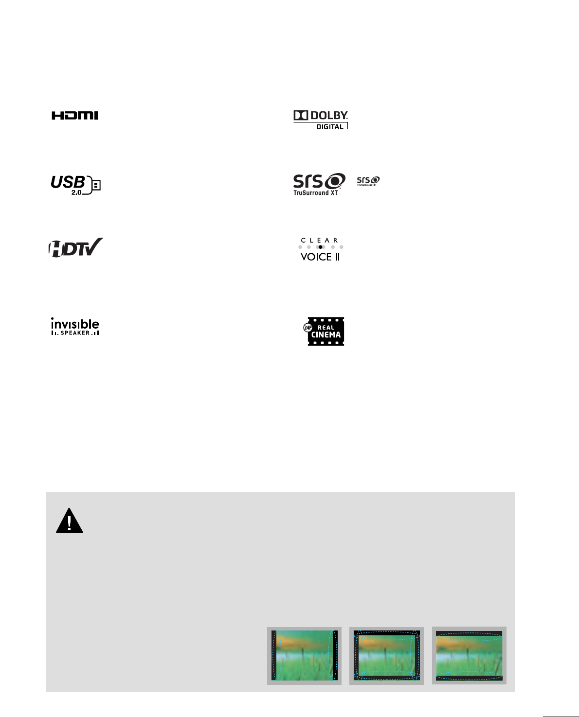
HDMITM, the HDMI logo and High-Definition
Multimedia Interface are trademarks or registered
trademarks of HDMI Licensing LLC."
■
When a fixed image (e.g. logos, screen menus, video game, and computer display) is displayed on the TV
for an extended period, it can become permanently imprinted on the screen. This phenomenon is known
as “image burn” or “burn-in.” Image burn is not covered under the manufacturer’s warranty.
■
In order to prevent image burn, avoid displaying a fixed image on your TV screen for a prolonged period
(2 or more hours for LCD, 1 or more hours for Plasma).
■
Image burn can also occur on the letterboxed
areas of your TV if you use the 4:3 aspect
ratio setting for an extended period.
IMPORTANT INFORMATION TO PREVENT “IMAGE BURN
/ BURN-IN” ON YOUR TV SCREEN
High-definition television. High-resolution digital
television broadcast and playback system composed
of roughly a million or more pixels, 16:9 aspect-ratio
screens, and AC3 digital audio. A subset of digital
television, HDTV formats include 1080i and 720p
resolutions.
View videos and photos and listen to music on your
TV through USB 2.0 (‘videos’ dependent on model).
LG TV include a unique invisible speaker system,
tuned by renowned audio expert, Mr. Mark Levinson.
Speakers are embedded in strategic spots behind the
front cabinet and use minute vibrations to turn the
entire front bezel into the speaker system. The result
is a clean, polished look, and enhanced audio by
increasing the “sweet spot”, giving a wider and richer
sound field.
Automatically enhances and amplifies the sound of
human voice frequency range to help keep dialogue
audible when background noise swells.
Matches the original frame rate of the film for a more
film-like experience
8
PREPERATION
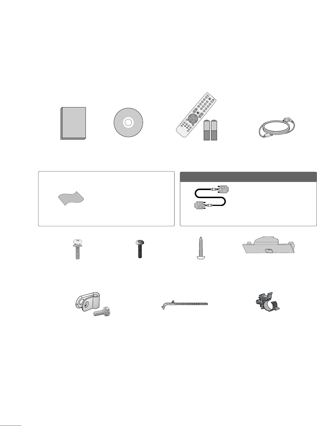
ACCESSORIES
Ensure that the following accessories are included with your TV. If an accessory is missing, please contact the
dealer where you purchased the TV.
The accessories included may differ from the images below.
1.5V 1.5V
Owner’s Manual Power Cord
Remote Control,
Batteries
LIST
3
56
78
0
9
FLASHBK
MUTE
VOL
CH
P
A
G
E
RETURN
ENTER
MENU
LIST
123
456
78
0
9
FLASHBK
MUTE
VOL
CH
P
A
G
E
RETURN
MARK
ENTER
INPUT
POWER
RATIO
CC
TIMER
ALAM
SAP
EJECT
CD Manual
Bolts for stand assembly
(Refer to P.12) Screw for stand fixing
(Refer to P.17)
Protection Cover
(Refer to P.13)
x 4
OOppttiioonn EExxttrraass
* Wipe spots on the exterior only with
the polishing cloth.
* Do not wipe roughly when removing
stain. Excessive pressure may cause
scratch or discoloration.
Polishing Cloth
Not included with all models
D-sub 15 pin Cable
When using the VGA (D-sub 15 pin
cable) PC connection, the user
must use shielded signal interface
cables with ferrite cores to maintain
standards compliance.
Protective Bracket and Bolt for
Power Cord
(This feature is not available for all models.)
(Refer to P.15)
Cable Holder
(Refer to P.15)
Plug in type holder
(Refer to P.15)
x 2
Torx plus
Star head screw
(Refer to P.12)
PREPARATION
9
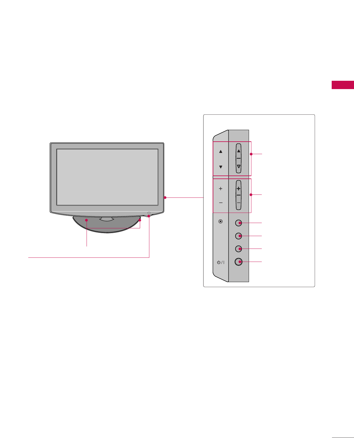
FRONT PANEL INFORMATION
■
Image shown may differ from your TV.
INPUT
MENU
ENTER
CH
VOL
CHANNEL (DD,EE)
Buttons
VOLUME (+, -)
Buttons
ENTER Button
MENU Button
INPUT Button
POWER Button
SPEAKER
Remote Control Sensor,
Power/Standby Indicator
Illuminates red in standby mode.
Illuminates blue when the TV is switched on.
PREPARATION
10
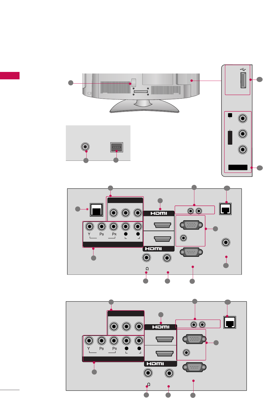
■
Image shown may differ from your TV.
BACK PANEL INFORMATION
AV IN 2
L/MONO
R
AUDIO
VIDEO
USB IN
RS-232C IN
(
SERVICE ONLY)
AUDIO IN
VIDEO
AUDIO
RGB IN (PC)
VIDEO AUDIO
L(MONO)
R
2
1
L R
/DVI IN
COMPONENT IN
AV IN 1
UPDATE
RESET
(RGB/DVI)
REMOTE
CONTROL OUT
SPEAKER OUT
(8 )
RJP
TV - LINK
CFG
GAME
CONTROL
R
8
210
R
( )
ANTENNA IN
ANTENNA IN
M.P.I.
M.P.I.
7
1
4
3
56
12
13
15
14
2
PREPARATION
9
11
RS-232C IN
(
SERVICE ONLY)
AUDIO IN
VIDEO
AUDIO
RGB IN (PC)
VIDEO AUDIO
L(MONO)
R
2
1
L R
/DVI IN
COMPONENT IN
AV IN 1
UPDATE
RESET
(RGB/DVI)
REMOTE
CONTROL OUT
SPEAKER OUT
(8 )
RJP
R
8
210
7
4
3
569
32/37/42LH250H, 32/37/42LH255H, 37/42LH260H
32LH240H

PREPARATION
11
RJP (REMOTE JACK PACK PORT)
Connect to remote jack pack control output port.
TV - LINK CFG
Used for FTG Configuration
USB IN
Used for viewing photos and listening to MP3s.
ANTENNA IN
Connect over-the air signals to this jack.
M.P. I.
Control port.
Power Cord Socket
For operation with AC power.
Caution: Never attempt to operate the TV on DC
power.
GAME CONTROL
Control port
AV (Audio/Video) IN
Analog composite connection. Supports standard
definition video only (480i).
Used for PC/DTV audio input jack.
COMPONENT IN
Analog Connection.
Supports HD.
Uses a red, green, and blue cable for video & a red
and white cable for audio.
HDMI/DVI IN
Digital Connection. Supports HD video and Digital
audio.
Accepts DVI video using an adapter or HDMI to
DVI cable (not included)
SPEAKER OUT 8Ω
Connect to external speaker input.
REMOTE CONTROL OUT
IR output for controlling an auxiliary device.
UPDATE
Enables/disables software downloads and debug
mode.
RESET
Performs a hardware reset.
RGB IN (PC)
Analog PC Connection. Uses a D-sub 15 pin cable
(VGA cable).
AUDIO IN (RGB/DVI)
1/8” headphone jack for analog PC audio input.
RS-232C IN (SERVICE ONLY)
Used for software updates.
1
2
3
4
5
9
8
6
7
10
11
12
13
14
15
PREPARATION
12
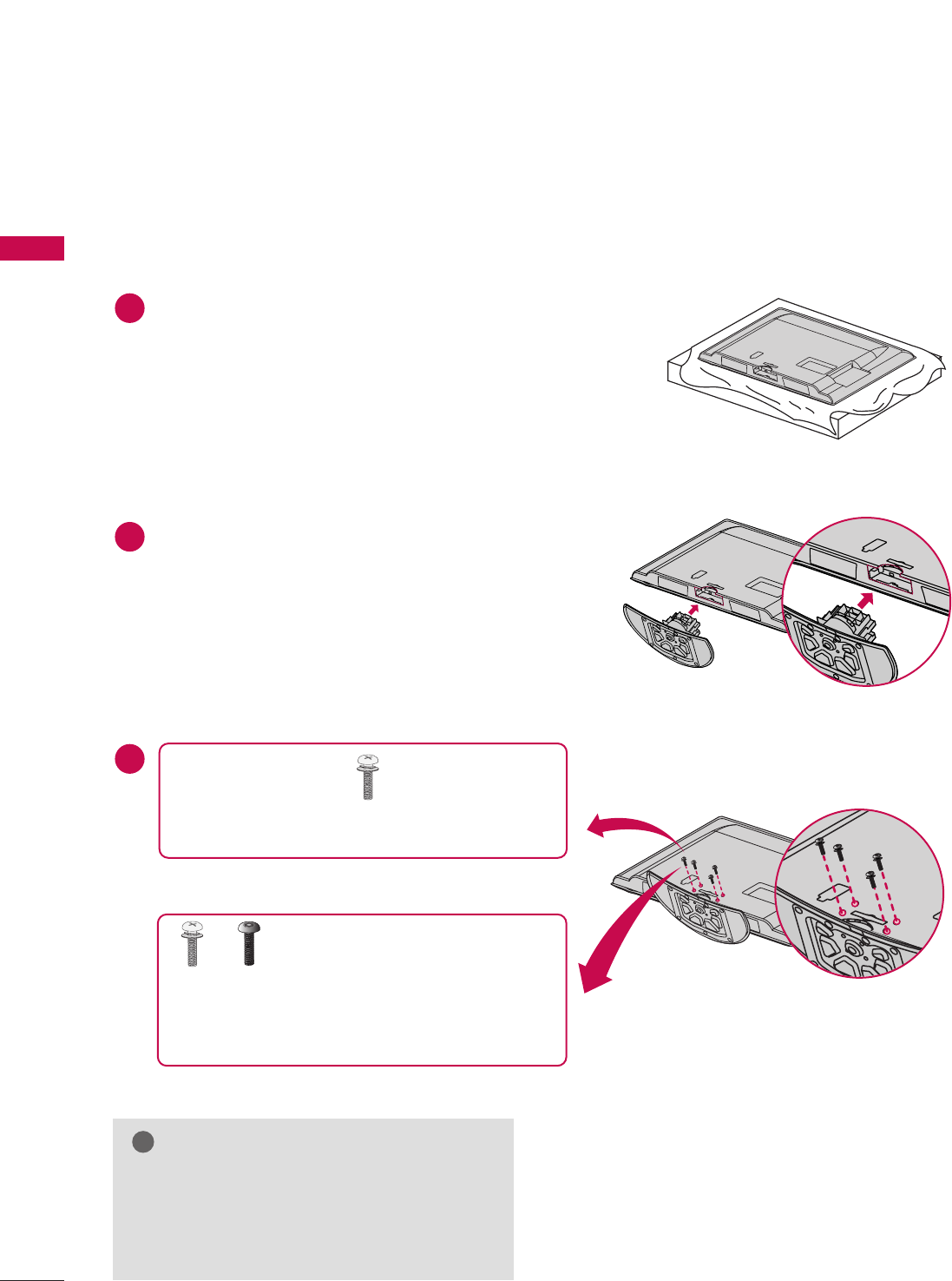
STAND INSTRUCTION
PREPARATION
■
Image shown may differ from your TV.
Carefully place the TV screen side down on a
cushioned surface to protect the screen from
damage.
Assemble the TV as shown.
1
2
3
INSTALLATION
GGWhen assembling the desk type stand, make sure
the bolt is fully tightened (If not tightened fully,
the TV can tilt forward after the product installa-
tion). Do not over tighten.
NOTE
!
x 4
Tighten the stand with the four screws (provided as
parts of the TV).
or
Tighten the two of these four screws
and the two Torx plus star head
screws (provided as parts of the TV) to secure the
TV. Tighten the two Torx plus star head screws with
a star head driver bit (not provided as parts of the
TV).
x 2 x 2
PREPARATION
13
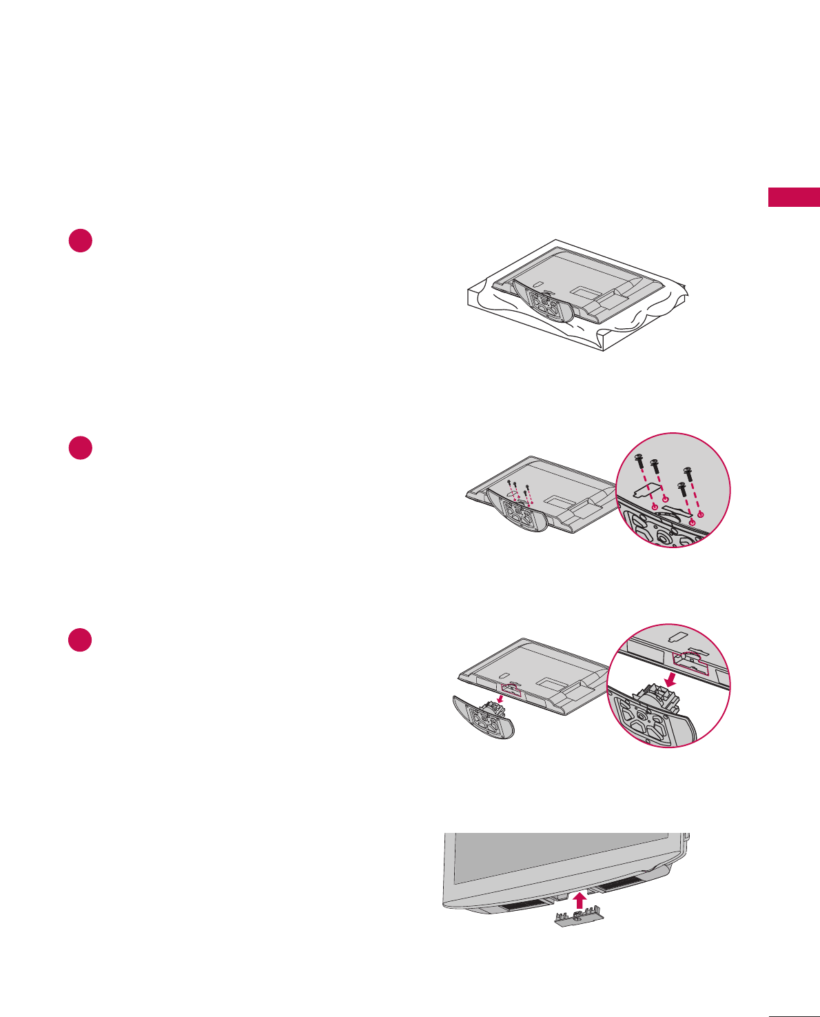
DETACHMENT
Carefully place the TV screen side down on a
cushioned surface to protect the screen from
damage.
1
Loose the bolts from TV.
2
Detach the stand from TV.
3
After removing the stand, install the included
pprrootteeccttiioonn ccoovveerrover the hole for the stand.
Press the PPRROOTTEECCTTIIOONN CCOOVVEERRinto the TV
until you hear it click.
PROTECTION COVER
PREPARATION
14
PREPARATION
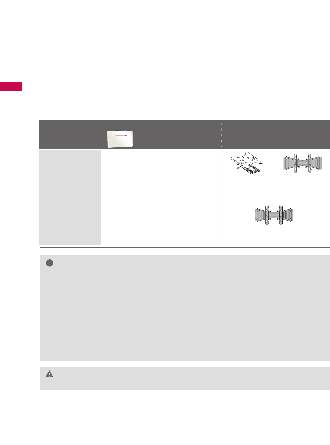
VESA WALL MOUNTING
Install your wall mount on a solid wall perpendicular to the floor. When attaching to other building materials, please
contact your nearest installer.
If installed on a ceiling or slanted wall, it may fall and result in severe personal injury.
We recommend that you use an LG brand wall mount when mounting the TV to a wall.
LG recommends that wall mounting be performed by a qualified professional installer.
GGDo not install your wall mount kit while your TV is turned on. It may result in personal
injury due to electric shock.
CAUTION
GGScrew length needed depends on the wall mount
used. For further information, refer to the instruc-
tions included with the mount.
GGStandard dimensions for wall mount kits are shown
in the table.
GGWhen purchasing our wall mount kit, a detailed
installation manual and all parts necessary for
assembly are provided.
GGDo not use screws longer then the standard dimen-
sion, as they may cause damage to the inside to
the TV.
GGFor wall mounts that do not comply with the VESA
standard screw specifications, the length of the
screws may differ depending on their specifica-
tions.
GGDo not use screws that do not comply with the
VESA standard screw specifications.
Do not use fasten the screws too strongly, this may
damage the TV or cause the TV to a fall, leading to
personal injury. LG is not liable for these kinds of
accidents.
GGLG is not liable for TV damage or personal injury
when a non-VESA or non specified wall mount is
used or the consumer fails to follow the TV installa-
tion instructions.
NOTE
!
Model
VESA (A *B)
Standard Screw Quantity Wall Mounting Bracket
(sold separately)
37LH250H,
37LH255H,
37LH260H,
42LH250H,
42LH255H,
42LH260H
32LH240H,
32LH250H,
32LH255H
200 * 10 0 M 4 4
200 * 200 M6 4
AA
BB
RW230 AW-47LG30M
AW-47LG30M
PREPARATION
15
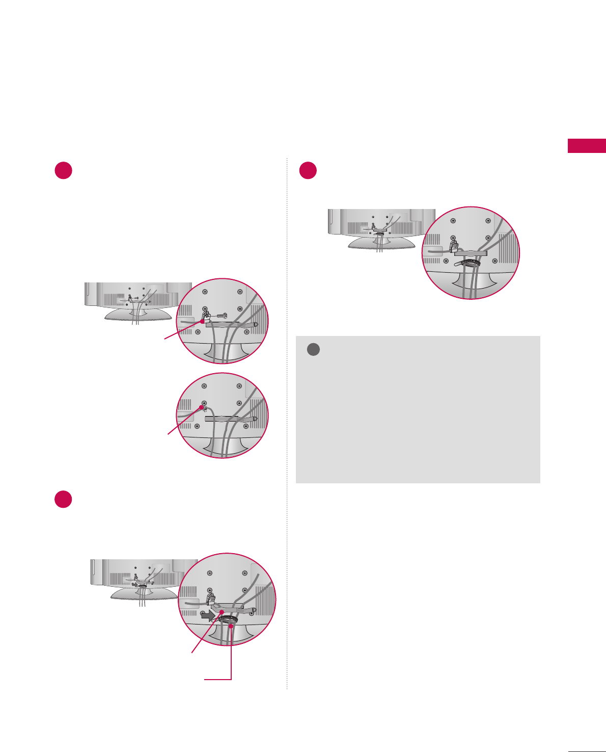
CABLE MANAGEMENT
■
Image shown may differ from your TV.
Connect the cables as necessary.
To connect additional equipment, see the
EXTERNAL EQUIPMENT SETUP section.
Secure the power cable with the PPROTECTIVE
BRACKET/Screw or the Plug in type Holder.
It will help prevent the power cable from
being removed by accident.
Install the CABLE MANAGEMENT CLIP as
shown.
If your TV has the CABLE HOLDER, install it
as shown and bundle the cables.
1
2
Put the cables inside the CABLE MANAGEMENT
CLIP and snap it closed.
3
GGDo not hold the CABLE MANAGEMENT CLIP
when moving the TV.
- If the TV is dropped, you may be injured or the
product may be broken.
GGWith some TVs, the PLUG IN TYPE HOLDER
and the CABLE HOLDER are included. If these
holders are inserted into the hole provided on
back of the TV, they cannot be removed.
NOTE
!
CABLE MANAGEMENT CLIP
CABLE HOLDER
PROTECTIVE BRACKET/Screw
(This feature is not available for
all models.)
PLUG IN TYPE HOLDER
Or
PREPARATION
16
PREPARATION
DESKTOP PEDESTAL INSTALLATION
SWIVEL STAND
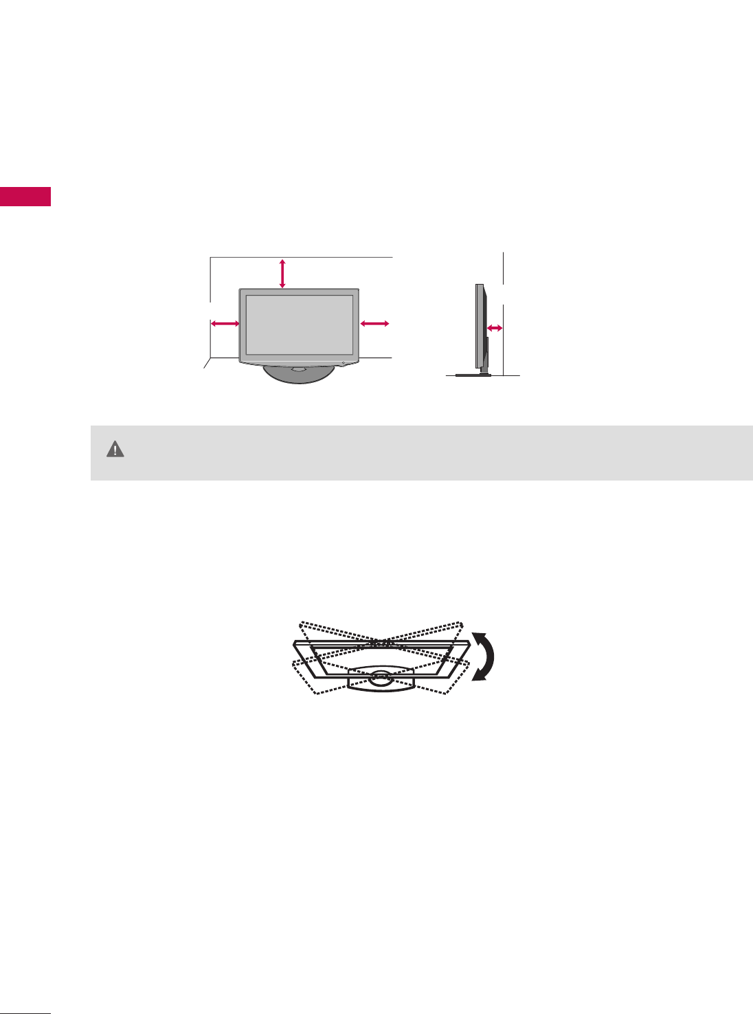
After installing the TV, you can adjust the TV set manually to the left or right direction by 90 degrees to suit
your viewing position.
For proper ventilation, allow a clearance of 4 inches on all four sides from the wall.
■
Image shown may differ from your TV.
4 inches
GGEnsure adequate ventilation by following the clearance recommendations.
GGDo not mount near or above any type of heat source.
CAUTION
4 inches
4 inches
4 inches
PREPARATION
17
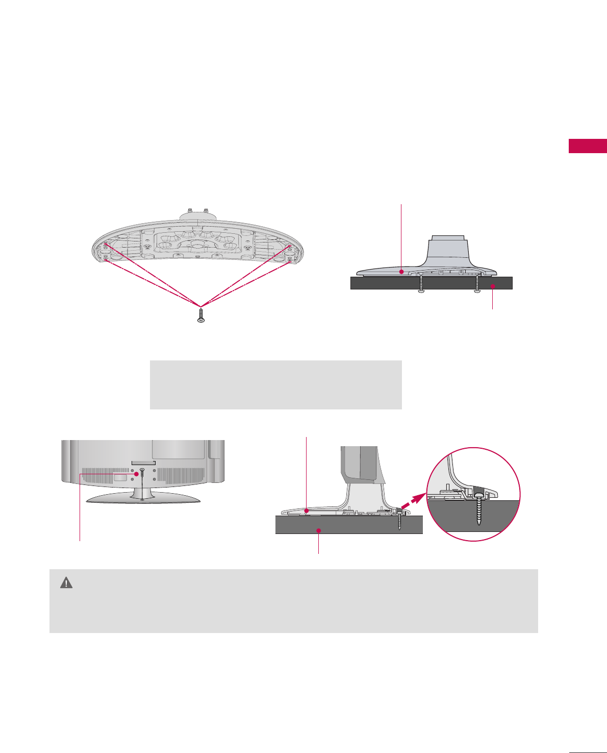
ATTACHING THE TV TO A DESK
GGTo prevent TV from falling over, the TV should be securely attached to the floor/wall per installation
instructions. Tipping, shaking, or rocking the machine may cause injury.
WARNING
1-Screw
(provided as parts of the product)
Desk
Stand
■
Image shown may differ from your TV.
The TV must be attached to a desk so it cannot be pulled in a forward/backward direction, potentially causing
injury or damaging the product.
GGScrew: M5 x L
(*L: Table depth + 8
~
10 mm)
ex) Table depth: 15mm, Screw: M5 x 25
4-Screws
(not provided as parts of the product)
Stand
Desk
PREPARATION
18
PREPARATION
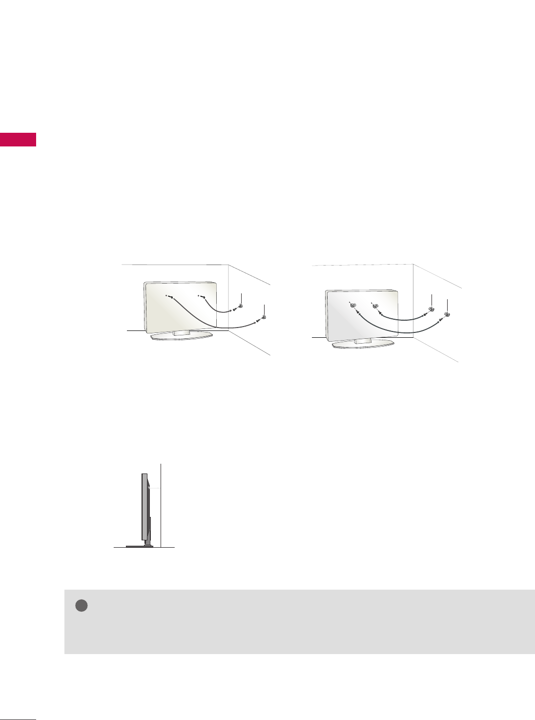
SECURING THE TV TO THE WALL TO PREVENT FALLING
WHEN THE TV IS USED ON A STAND
We recommend that you set up the TV close to a wall so it cannot fall over if pushed backwards.
Additionally, we recommend that the TV be attached to a wall so it cannot be pulled in a forward direction,
potentially causing injury or damaging the product.
Caution: Please make sure that children don’t climb on or hang from the TV.
■Insert the eye-bolts (or TV brackets and bolts) to tighten the product to the wall as shown in the picture.
*If your product has the bolts in the eye-bolts position before inserting the eye-bolts, loosen the bolts.
* Insert the eye-bolts or TV brackets/bolts and tighten them securely in the upper holes.
Secure the wall brackets with the bolts (sold separately) to the wall. Match the height of the bracket that is
mounted on the wall to the holes in the product.
Ensure the eye-bolts or brackets are tightened securely.
■Use a sturdy rope (sold separately) to tie the product. It is safer to tie
the rope so it becomes horizontal between the wall and the product.
■
You should purchase necessary components to prevent the TV from tipping over (when not using a wall mount).
■
Image shown may differ from your TV.
GGUse a platform or cabinet strong enough and large enough to support the size and weight of the TV.
GGTo use the TV safely make sure that the height of the bracket on the wall and the one on the TV are the same.
NOTE
!
PREPARATION
19
R
( )
ANTENNA INANTENNA IN M.P.I.
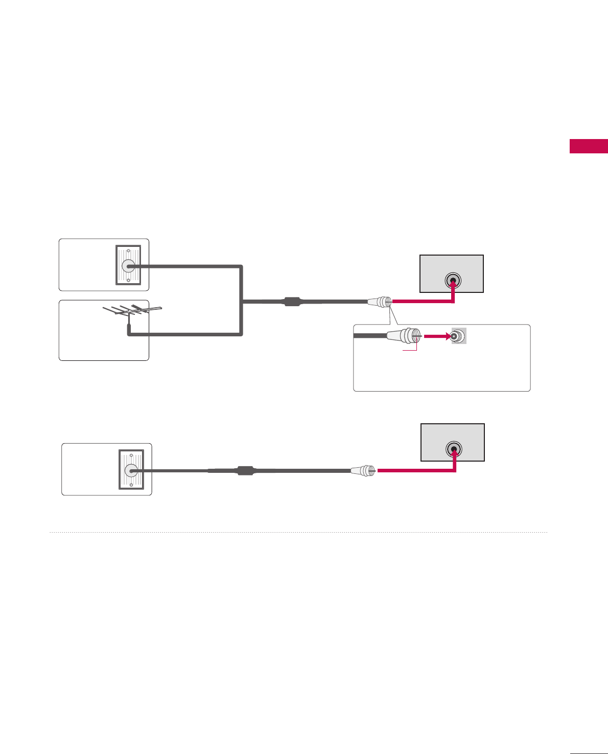
ANTENNA OR CABLE CONNECTION
1. Antenna (Analog or Digital)
Wall Antenna Socket or Outdoor Antenna without a Cable Box
Connection.
For optimum picture quality, adjust the direction if needed.
2. Cable
Wall
Antenna
Socket
Outdoor
Antenna
(VHF, UHF)
Cable TV
Wall Jack
Multi-family Dwellings/Apartments
(Connect to wall antenna socket)
RF Coaxial Wire (75 ohm)
RF Coaxial Wire (75 ohm)
Single-family Dwellings /Houses
(Connect to wall jack for outdoor antenna)
Be careful not to bend the copper wire
when connecting the antenna.
Copper Wire
■To improve the picture quality in a poor signal area, please purchase a signal amplifier and install properly.
■If the antenna needs to be split for two TV’s, install a 2-Way Signal Splitter.
■If the antenna is not installed properly, contact your dealer for assistance.
■To prevent damage do not connect to the power outlet until all connections are made between the devices.
R
( )
ANTENNA INANTENNA IN M.P.I.
PREPARATION
20
HD RECEIVER SETUP
EXTERNAL EQUIPMENT SETUP
This TV can receive Digital Over-the-air or Digital Cable signals without an external digital set-top box. However,
if you do receive digital signals from a digital set-top box or other digital external device, refer to the figure as
shown below.
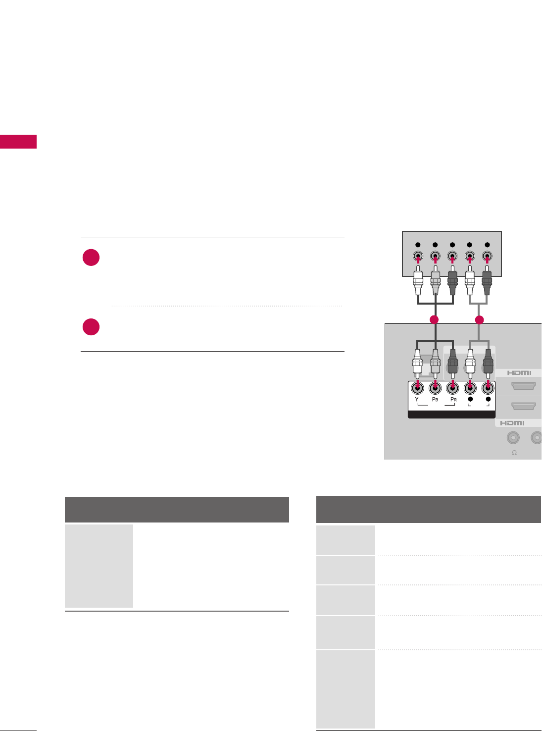
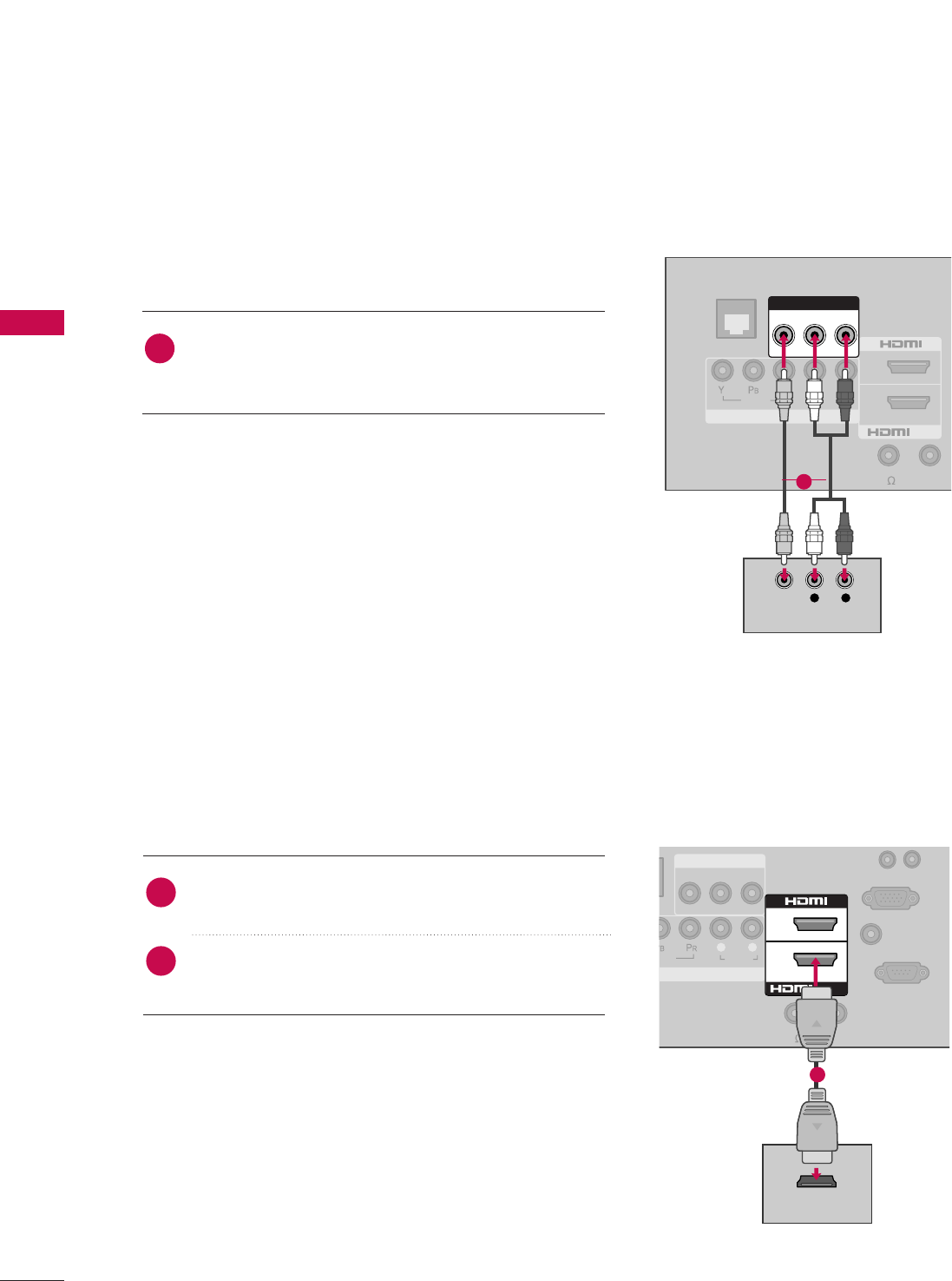
Component Connection
1. How to connect
Connect the video outputs (Y, PB, PR)of the digital set-
top box to the CCOOMMPPOONNEENNTT IINN VVIIDDEEOOjacks on
the TV. Match the jack colors (Y = green, PB= blue, and
PR= red).
Connect the audio output of the digital set-top box to
the CCOOMMPPOONNEENNTT IINN AAUUDDIIOOjacks on the TV.
2
1
2. How to use
■Turn on the digital set-top box.
(Refer to the owner’s manual for the digital set-top box.)
■Select CCoommppoonneennttinput source using the IINNPPUUTT button
on the remote control.
■To prevent the equipment damage, never plug in any power cords until you have finished connecting all equipment.
■Image shown may differ from your TV.
VIDEO AUDIO
L(MONO)
R
2
AV IN 1
Y L RPBPR
/DVI IN
1
VIDEO
AUDIO
COMPONENT IN
L R
GAME
CONTROL
SPEAKER OUT
REMOT
CONTROL
(8 )
12
Y, CB/PB, CR/PR
Supported Resolutions
Horizontal Vertical
Frequency(KHz)Frequency(Hz)
15.73 59.94
15.73 60.00
31.47 59.94
31.50 60.00
44.96 59.94
45.00 60.00
33.72 59.94
33.75 60.00
67.432 59.94
67.50 60.00
27.00 24.00
26.97 23.976
33.75 30.00
33.71 29.97
Resolution
720x480i
720x480p
1280x720p
1920x1080i
Signal
480i
480p
720p
108 0 i
1080 p
Component
Yes
Yes
Yes
Yes
Yes
HDMI
No
Yes
Yes
Yes
Yes
1920x1080p
EXTERNAL EQUIPMENT SETUP
21
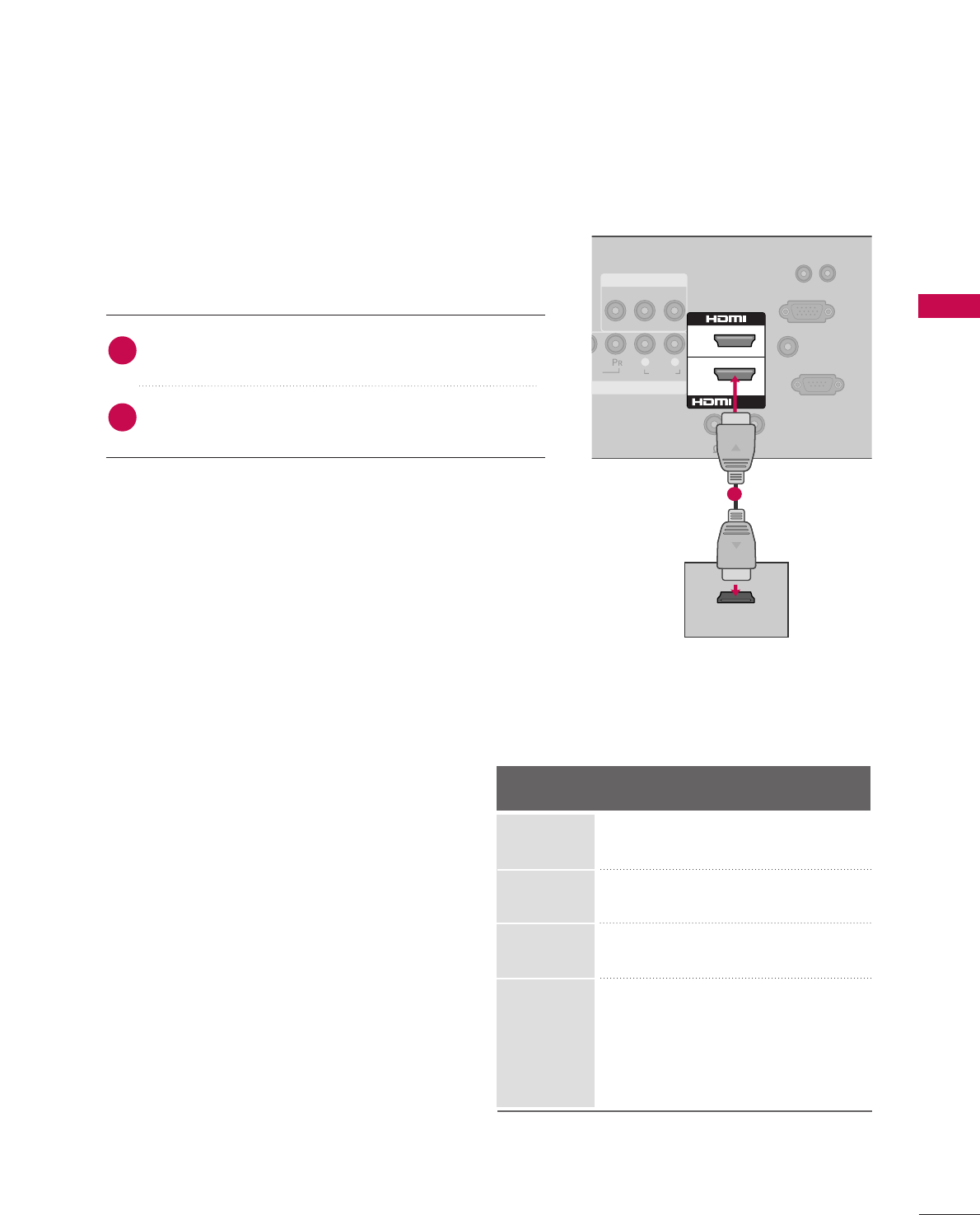
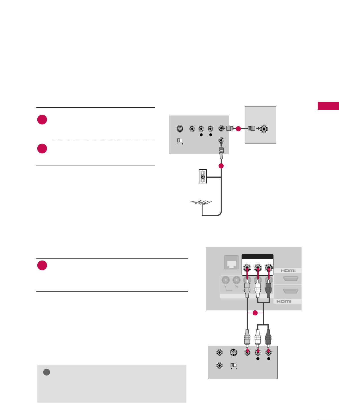
HDMI Connection
Connect the digital set-top box to HHDDMMII //DDVVII IINN 11
or HHDDMMII 22 jack on the TV.
No separate audio connection is necessary.
HDMI supports both audio and video.
1. How to connect
2. How to use
■Turn on the digital set-top box.
(Refer to the owner’s manual for the digital set-top box.)
■Select HHDDMMII11 or HHDDMMII22input source with using the IINNPPUUTT
button on the remote control.
2
1
HDMI-DTV
EO
AUDIO
VIDEO AUDIO
L(MONO)
R
AV IN 1
MPONENT IN
L R
2
1
/DVI IN
AUDIO IN
UPDATE
RESET
(RGB/DVI)
RS-232C IN
(
SERVICE ONLY)
SPEAKER OUT
RGB IN (PC)
REMOTE
CONTROL OUT
8(8 )
HDMI OUTPUT
1
Horizontal Vertical
Frequency(KHz)Frequency(Hz)
31.47 59.94
31.47 60.00
44.96 59.94
45.00 60.00
33.72 59.94
33.75 60.00
67.432 59.939
67.50 60.00
27.00 24.00
26.97 23.976
33.75 30.00
33.71 29.97
Resolution
720x480p
1280x720p
1920x1080i
1920x1080p
EXTERNAL EQUIPMENT SETUP
22
EXTERNAL EQUIPMENT SETUP
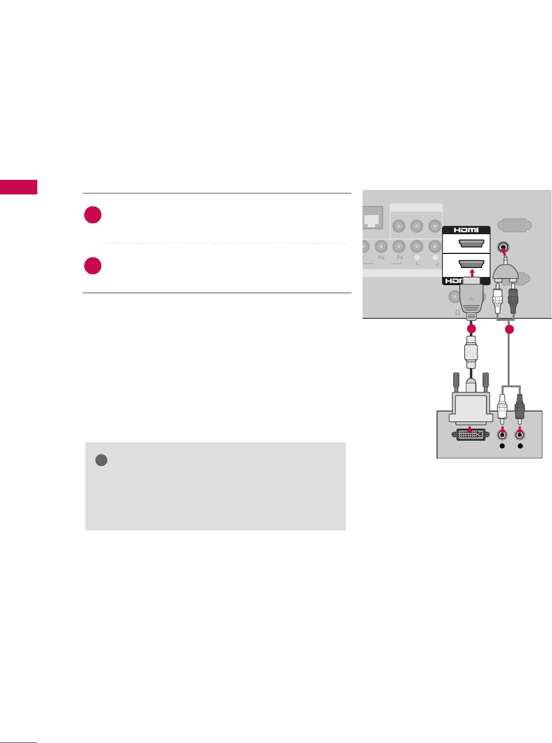
DVI to HDMI Connection
RS-232C IN
(
SERVICE ONLY)
VIDEO
AUDIO
RGB IN (PC)
VIDEO AUDIO
L(MONO)
R
AV IN 1
COMPONENT IN
L R
L R
DVI OUTPUT AUDIO
2
1
/DVI IN
GAME
ONTROL
AUDIO IN
(RGB/DVI)
REMOTE
CONTROL OUT
SPEAKER OUT
(8 )
12
GGA DVI to HDMI cable or adapter is required for this
connection. DVI doesn't support audio, so a separate
audio connection is necessary.
NOTE
!
Connect the DVI output of the digital set-top box to
the HHDDMMII//DDVVII IINN 11jack on the TV.
Connect the audio output of the digital set-top box to
the AAUUDDIIOO IINN ((RRGGBB//DDVVII))jack on the TV.
1. How to connect
2. How to use
■Turn on the digital set-top box. (Refer to the owner’s man-
ual for the digital set-top box.)
■Select the HHDDMMII11input source on the TV using the
IINNPPUUTTbutton on the remote control.
2
1
EXTERNAL EQUIPMENT SETUP
23
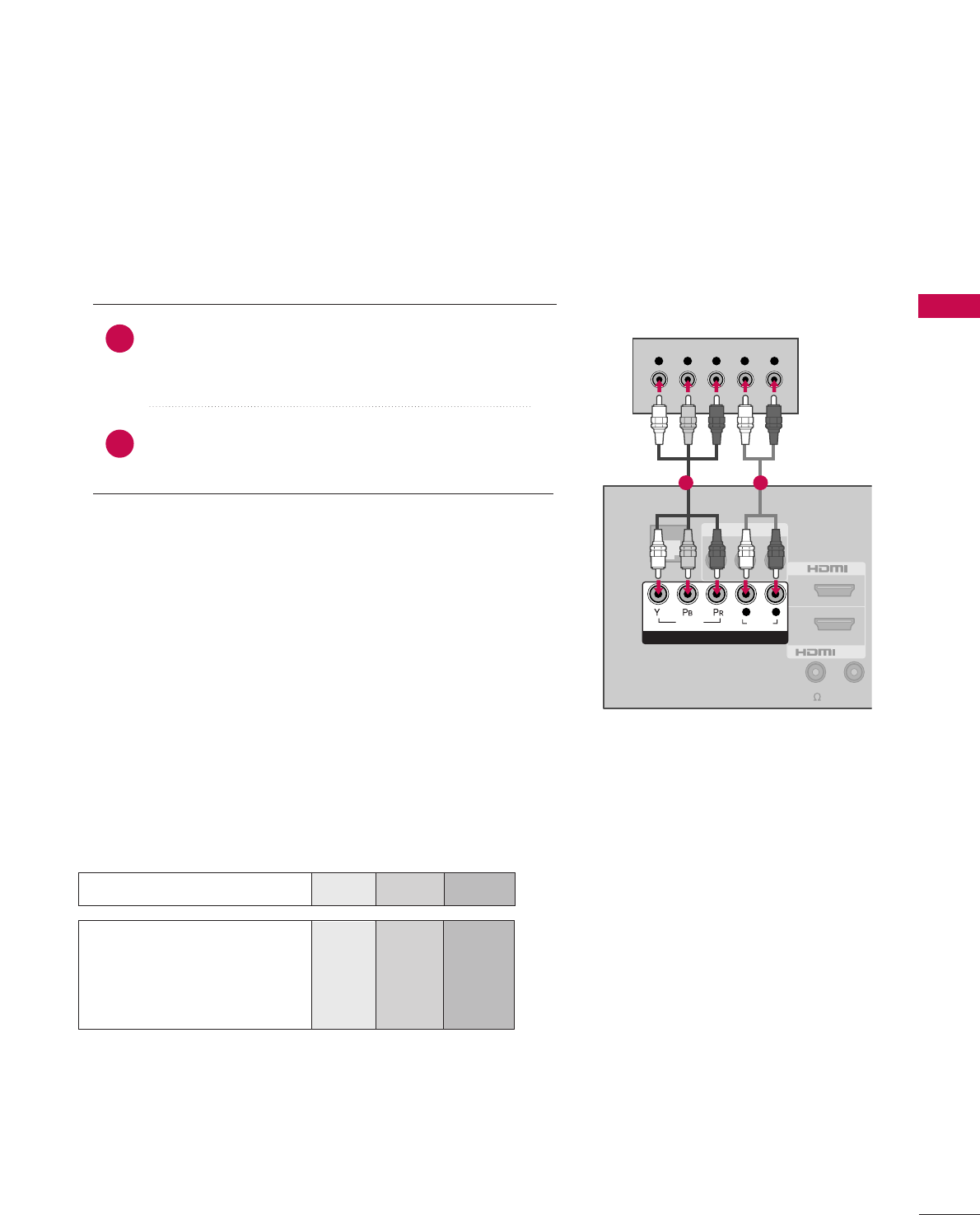
DVD SETUP
Component Connection
Component Input ports
To get better picture quality, connect a DVD player to the component input ports as shown below.
Component ports on the TV
YPBPR
Video output ports
on DVD player
Y
Y
Y
Y
PB
B-Y
Cb
Pb
PR
R-Y
Cr
Pr
Connect the video outputs (Y, PB, PR)of the DVD to the
CCOOMMPPOONNEENNTT IINN VVIIDDEEOOjacks on the TV.
Match the jack colors (Y = green, PB= blue, and PR= red).
Connect the audio outputs of the DVD to the
CCOOMMPPOONNEENNTT IINN AAUUDDIIOOjacks on the TV.
1. How to connect
2. How to use
■Turn on the DVD player, insert a DVD.
■Select the CCoommppoonneennttinput source on the TV using the
IINNPPUUTTbutton on the remote control.
■Refer to the DVD player's manual for operating instructions.
2
1
VIDEO AUDIO
L(MONO)
R
AV IN 1
Y L RPBPR
2
1
/DVI IN
VIDEO
AUDIO
COMPONENT IN
L R
GAME
CONTROL
R
(
SPEAKER OUT
REMOTE
CONTROL O
(8 )
1 2
EXTERNAL EQUIPMENT SETUP
24
EXTERNAL EQUIPMENT SETUP
HDMI Connection
Connect the HDMI output of the DVD to the
HHDDMMII//DDVVII IINN 11 or HHDDMMII 22jack on the TV.
No separate audio connection is necessary.
HDMI supports both audio and video.
1. How to connect
2. How to use
■Select the HHDDMMII11 or HHDDMMII22input source on the TV
using the IINNPPUUTTbutton on the remote control.
■Refer to the DVD player's manual for operating instructions.
2
1
DEO
AUDIO
VIDEO AUDIO
L(MONO)
R
AV IN 1
OMPONENT IN
L R
2
1
/DVI IN
OL
AUDIO IN
UPDATE
RESET
(RGB/DVI)
RS-232C IN
(
SERVICE ONLY)
SPEAKER OUT
RGB IN (PC)
REMOTE
CONTROL OUT
(8 )
HDMI OUTPUT
1
Composite (RCA) Connection
VIDEO
AUDIO
COMPONENT IN
L R
2
1
/DVI IN
VIDEO AUDIO
L(MONO)
R
AV IN 1
L R
VIDEO
AUDIO
GAME
CONTROL
A
RE
(R
SPEAKER OUT
REMOTE
CONTROL OU
(8 )
Connect the AAUUDDIIOO/VVIIDDEEOOjacks between TV and
DVD. Match the jack colors (Video = yellow, Audio Left
= white, and Audio Right = red).
1. How to connect
2. How to use
■Turn on the DVD player, insert a DVD.
■Select the or AAVV11 input source on the TV using the
IINNPPUUTTbutton on the remote control.
■If connected to AAVV IINN 22, select AAVV22input source on the TV.
■Refer to the DVD player's manual for operating instructions.
1
1
EXTERNAL EQUIPMENT SETUP
25
VCR SETUP
Antenna Connection
L R
S-VIDEO VIDEO
OUTPUT
SWITCH
ANT IN
ANT OUT
ANTENNA IN M.P.I.
( )
( )
Wall Jack
Antenna
1
2
Connect the RF antenna out socket of the
VCR to the AANNTTEENNNNAA IINNsocket on the
TV.
Connect the antenna cable to the RF
antenna in socket of the VCR.
1. How to connect
2. How to use
■Set VCR output switch to 3 or 4 and then
tune TV to the same channel number.
■Insert a video tape into the VCR and press
PLAY on the VCR. (Refer to the VCR owner’s
manual.)
2
1
Composite (RCA) Connection
Connect the AAUUDDIIOO/VVIIDDEEOOjacks between TV and
VCR. Match the jack colors (Video = yellow, Audio Left
= white, and Audio Right = red)
1. How to connect
2. How to use
■Insert a video tape into the VCR and press PLAY on the
VCR. (Refer to the VCR owner’s manual.)
■Select the AAVV11input source on the TV using the IINNPPUUTT
button on the remote control.
■If connected to AAVV IINN 22, select AAVV22input source on the TV.
1
GGIf you have a mono VCR, connect the audio cable
from the VCR to the AAUUDDIIOO ((LL//MMOONNOO))jack of
the TV.
NOTE
!
L R
S-VIDEO VIDEO
AUDIO
OUTPUT
SWITCH
ANT IN
ANT OUT
VIDEO
AUDIO
COMPONENT IN
L R
VIDEO AUDIO
L(MONO)
R
AV IN
2
1
/DVI IN
GAME
CONTROL
1
EXTERNAL EQUIPMENT SETUP
26
EXTERNAL EQUIPMENT SETUP
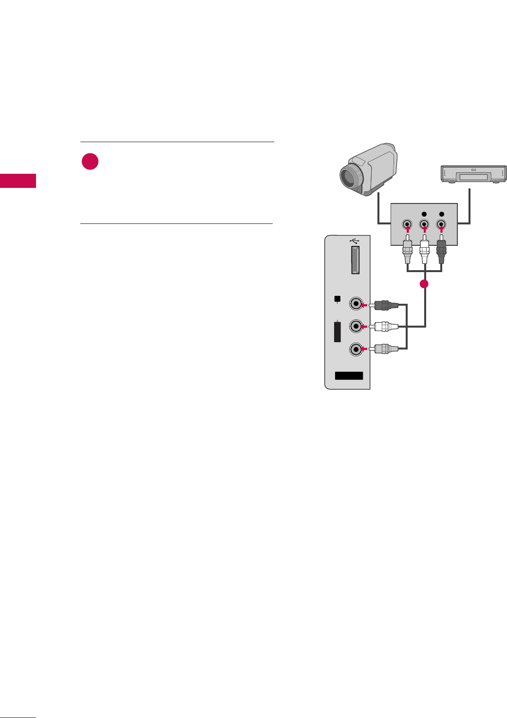
OTHER A/V SOURCE SETUP
AV IN 2
L/MONO
R
AUDIO
VIDEO
L R
VIDEO
USB IN
Camcorder
Video Game Set
Connect the AAUUDDIIOO/VVIIDDEEOOjacks
between TV and external equipment.
Match the jack colors
.
(Video = yellow, Audio Left = white, and
Audio Right = red)
1. How to connect
2. How to use
■Select the AAVV22input source on the TV using the
IINNPPUUTTbutton on the remote control.
■If connected to AAVV IINN 11input, select the AAVV11
input source on the TV.
■Operate the corresponding external equipment.
1
1
EXTERNAL EQUIPMENT SETUP
27
PC SETUP
This TV provides Plug and Play capability, meaning that the PC adjusts automatically to the TV's settings.
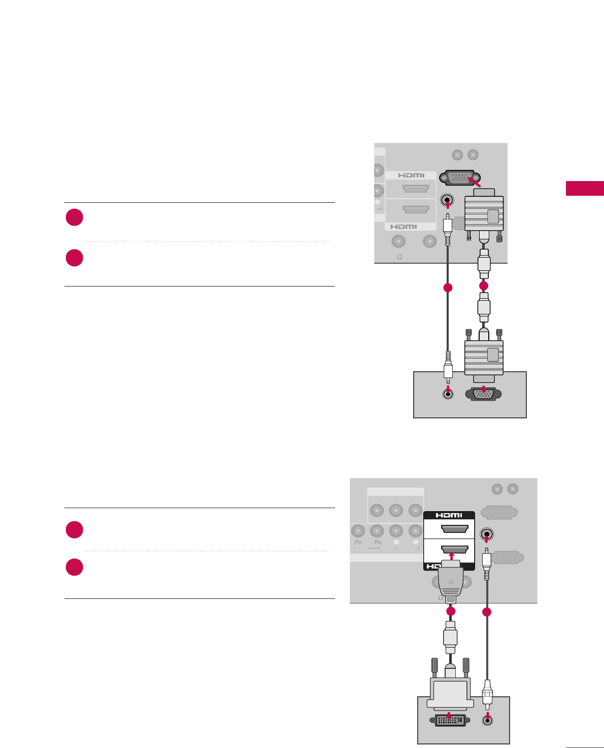
VGA (D-Sub 15 pin) Connection
O
O
R
R
RGB OUTPUT
AUDIO
2
1
/DVI IN
AUDIO IN
RGB IN (PC)
UPDATE
RESET
(RGB/DVI)
RS-232C IN
(
SERVICE ONLY)
REMOTE
CONTROL OUT
SPEAKER OUT
(8 )
1
2
2. How to use
■Turn on the PC and the TV.
■Select the RRGGBB--PPCCinput source on the TV using the
IINNPPUUTTbutton on the remote control.
Connect the VGA output of the PC to the RRGGBB IINN
((PPCC)) jack on the TV.
Connect the PC audio output to the AAUUDDIIOO IINN
((RRGGBB//DDVVII))jack on the TV.
1. How to connect
2
1
DVI to HDMI Connection
VIDEO
AUDIO
VIDEO AUDIO
L(MONO)
R
AV IN 1
COMPONENT IN
L R
AUDIO
DVI OUTPUT
2
1
/DVI IN
AUDIO IN
UPDATE
RESET
(RGB/DVI)
RS-232C IN
(
SERVICE ONLY)
SPEAKER OUT
RGB IN (PC)
REMOTE
CONTROL OUT
(8 )
12
2. How to use
■Turn on the PC and the TV.
■Select the HHDDMMII11 input source on the TV using the
IINNPPUUTTbutton on the remote control.
Connect the DVI output of the PC to the HHDDMMII//DDVVII IINN
11jack on the TV.
Connect the PC audio output to the AAUUDDIIOOIINN
((RRGGBB//DDVVII)) jack on the TV.
1. How to connect
2
1
EXTERNAL EQUIPMENT SETUP
28
EXTERNAL EQUIPMENT SETUP
GGTo get the best picture quality, adjust the PC graphics card to 1360x768, 60Hz.
GGDepending on the graphics card, DOS mode may not work if a HDMI to DVI Cable is in use.
GGIn PC mode, there may be noise associated with the resolution, vertical pattern, contrast or brightness. If
noise is present, change the PC output to another resolution, change the refresh rate to another rate or
adjust the brightness and contrast on the PICTURE menu until the picture is clear.
NOTES
!
Supported Display Specifications
(RGB-PC, HDMI-PC)
Resolution
640x480
1360x768
640x350
720x400
800x600
1024x768
Horizontal Vertical
Frequency(KHz)Frequency(Hz)
31.469 70.08
31.469 59.94
31.469 70.08
37.879 60.31
48.363 60.00
47.776 59.87
47.720 59.799
47.13 59.65
When you use too long RGB-PC cable, there might be a noise on the screen.
GGAvoid keeping a fixed image on the screen for a long period of time. The fixed image could become per-
manently imprinted on the screen.
GGThe synchronization input form for Horizontal and Vertical frequencies is separate.
GGDepending on the graphics card, some resolution settings may not allow the image to be positioned on
the screen properly.
1280x768
1366x768
Resolution
640x480
1360x768
640x350
720x400
800x600
1024x768
Horizontal Vertical
Frequency(KHz)Frequency(Hz)
31.468 70.09
31.469 59.9
31.469 70.08
35.156 56.25
37.879 60.31
48.363 60.00
56.476 70.06
47.776 59.870
47.712 60.015
63.981 60.020
75.00 60.00
66.587 59.934
1280x768
1280x1024
(For 37/42LH260H)
1600x1200
1920x1080
EXTERNAL EQUIPMENT SETUP
33
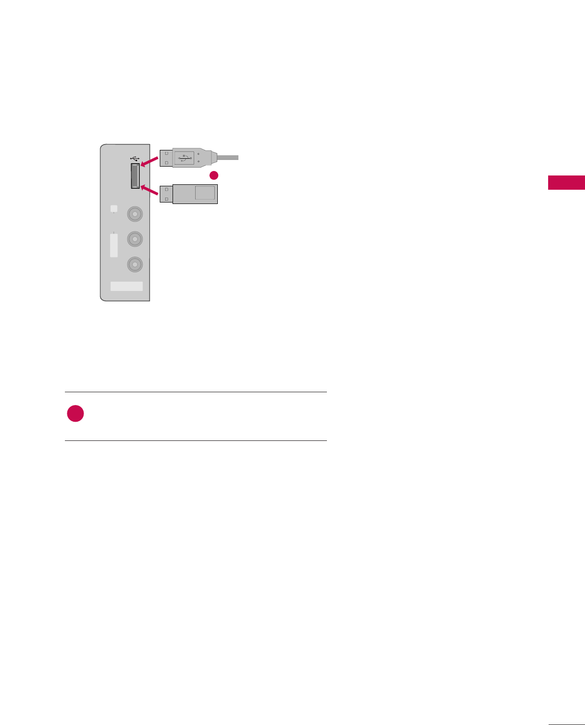
USB CONNECTION
USB IN
AV IN 2
L/MONO
R
AUDIO
VIDEO
Memory Key
Connect the USB device to the UUSSBB IINNjack on the side
of TV.
1. How to connect
1
2. How to use
■After connecting the UUSSBB IINNjack, you use the USB func-
tion. (GGpp..4433)
1
or
USB
43
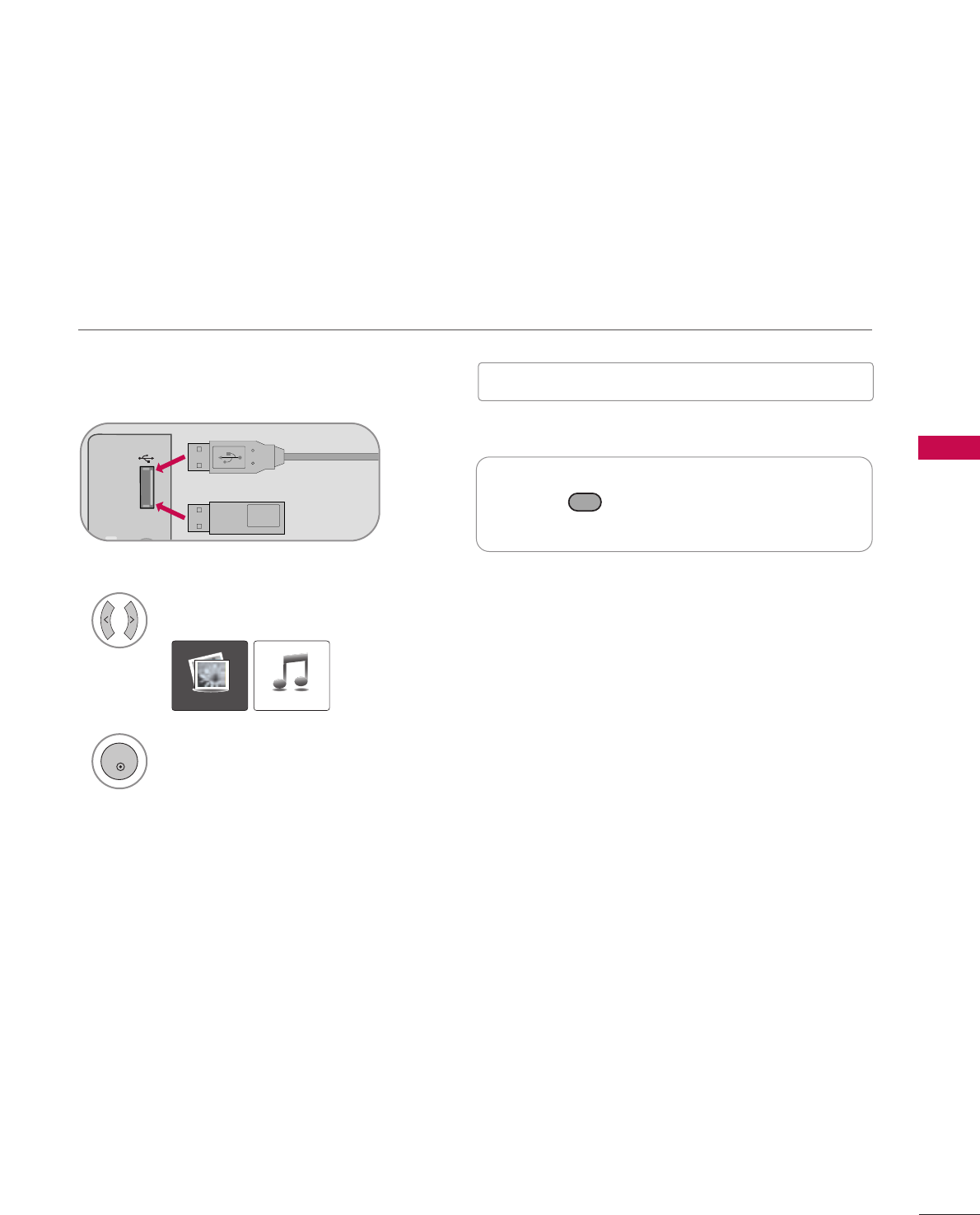
USB
When removing the USB device
USB IN
R
Memory Key
Connect the USB device to the UUSSBB IINN
jacks on the side of TV.
3
Select PPHHOOTTOO LLIISSTTor MMUUSSIICCLLIISSTT.
1
Press the button before removing the USB
device.
2
EJECT
■This TV Supports on JPG and MP3.
When you connect a USB device, this pop up menu is displayed automatically.
When the Pop Up menu does not appear, you can select Photo List or Music List in the USB menu.
On a USB device, you can not add a new folder or delete an existing folder.
or
■
Image shown may differ from your TV.
PHOTO LIST MUSIC LIST
ENTRY MODES
ENTER

USB
44
Precautions when using the USB device
GGOnly a USB storage device is recognizable.
GGIf the USB storage device is connected through a USB hub, the device is not recognizable.
GGA USB storage device using an automatic recognition program may not be recognized.
GGA USB storage device which uses its own driver may not be recognized.
GGThe recognition speed of a USB storage device may depend on each device.
GGIn case of a card reader, up to four memory cards are concurrently recognizable.
GGPlease do not turn off the TV or unplug the USB device when the connected USB storage device is working.
When such device is suddenly separated or unplugged, the stored files or the USB storage device may be dam-
aged.
GGOnly use a USB storage device which has normal music, image or movie files.
GGPlease connect power to a USB storage device (over 0.5A) which requires an external power supply. If not, the
device may not be recognized.
GGPlease connect a USB storage device with cable is offered by USB maker. If connected with cable is not offered
by USB maker or an excessively long cable, the device may not be recognized.
GGSome USB storage devices may not be supported or operate properly.
GGFile alignment method of USB storage device is similar to Window XP and filename can recognize up to 100
English characters.
GGPlease backup important files because data on the USB device may be damaged. Data management is the con-
sumer's responsibility and as a result, the manufacturer does not cover data damage.
GG
Please use only a USB storage device which was formatted as a FAT32, NTFS file system provided with the Windows
operating system. In case of a storage device formatted as a different utility programme which is not supported by
Windows, it may not be recognized.
GG
Data in a USB storage device cannot be deleted in the NTFS file system.
GGIf your USB memory device has multiple partitions, or if you use a USB multi-card reader, you can use up to 4
partitions or USB memory devices.
GG
The recommended capacity is 1TB or less for a USB external hard disk and 32GB or less for USB memory.
GG
Any device with more than the recommended capacity may not work properly.
GG
If a USB external hard disk with a "Energy Saving" function does not work, turn the hard disk off and on again to make
it work properly.
Refer to the user manual of the application USB external hard disk.
GG
When using a USB HDD via the USB extensing cable, connect a support electric power source.
APPENDIX
89
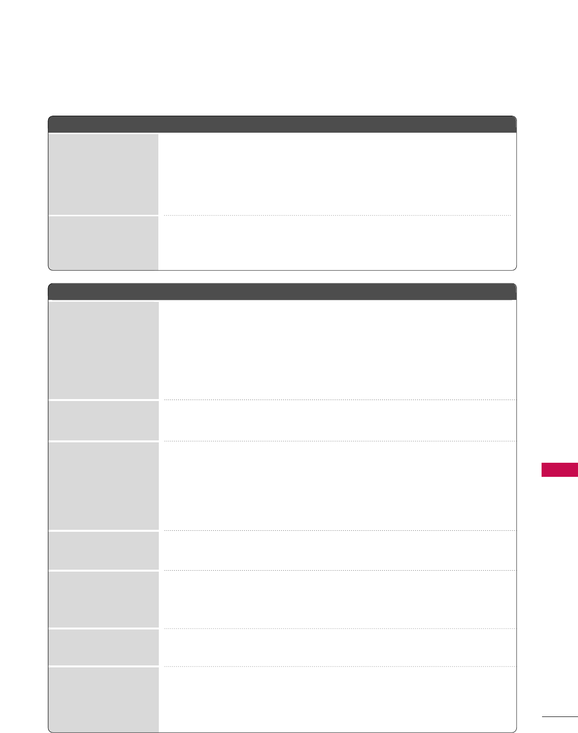
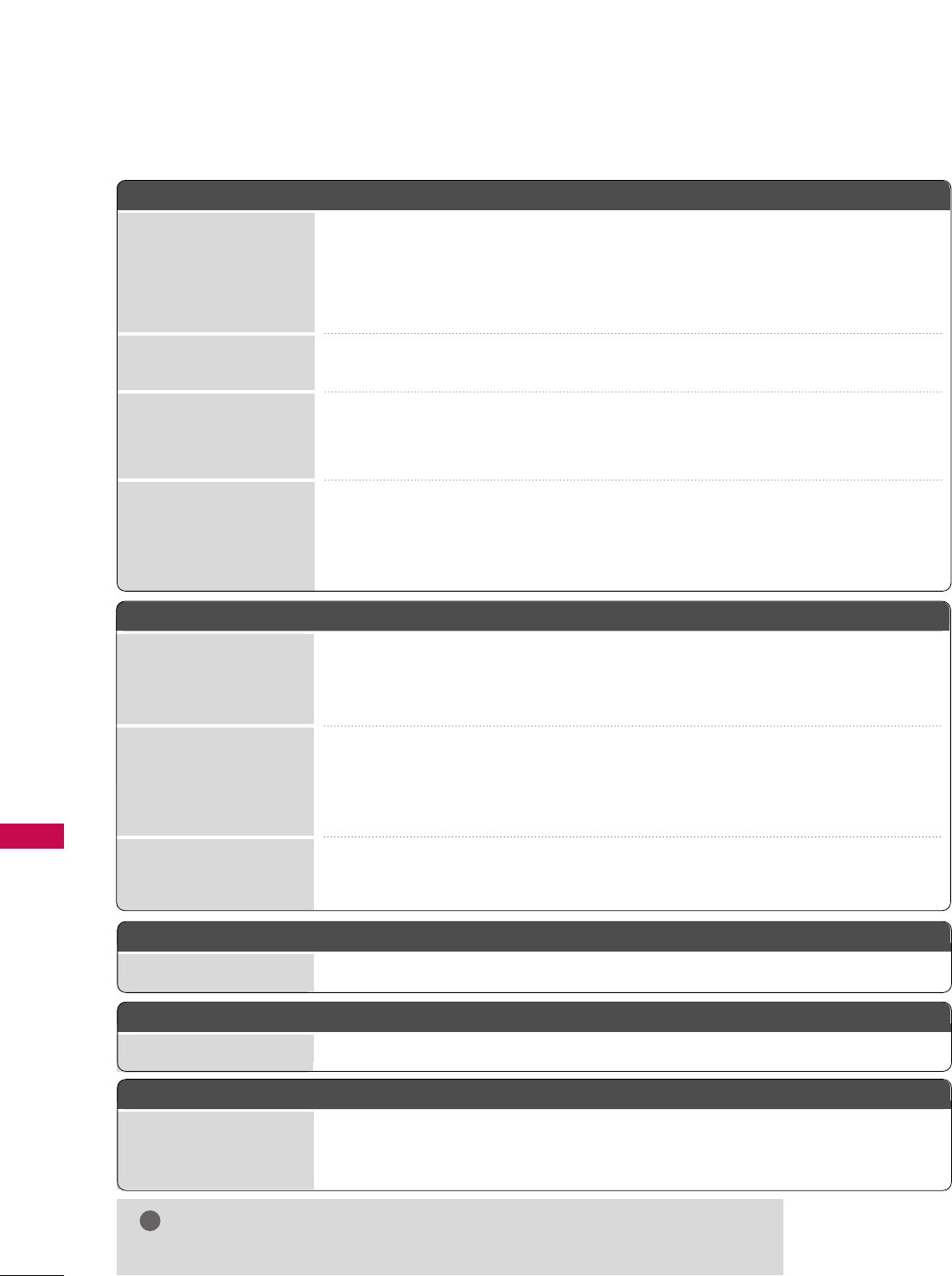
TROUBLESHOOTING
APPENDIX
TThhee ooppeerraattiioonn ddooeess nnoott wwoorrkk nnoorrmmaallllyy..
TThhee vviiddeeoo ddooeess nnoott wwoorrkk..
No picture &No sound
No or poor color
or poor picture
Poor reception on
some channels
Lines or streaks
in pictures
No picture
when connecting HDMI
Horizontal/vertical bars
or picture shaking
Picture appears slowly
after switching on
The remote control
doesn’t work
Power is suddenly
turned off
■Check to see if there is any object between the product and the remote control
causing obstruction. Ensure you are pointing the remote control directly at the TV.
■Ensure that the batteries are installed with correct polarity (+ to +, - to -).
■Ensure that the correct remote operating mode is set: TV, VCR etc.
■Install new batteries.
■Is the sleep timer set?
■Check the power control settings. Power interrupted.
■TV will be automatically turned off, in case of no signal for 15 minutes.
■Check whether the product is turned on.
■Try another channel. The problem may be with the broadcast.
■Is the power cord inserted into wall power outlet?
■Check your antenna direction and/or location.
■Test the wall power outlet, plug another product’s power cord into the outlet
where the product’s power cord was plugged in.
■This is normal, the image is muted during the product startup process. Please
contact your service center, if the picture has not appeared after five minutes.
■Adjust Color in menu option.
■Keep a sufficient distance between the product and the VCR.
■Try another channel. The problem may be with the broadcast.
■Are the video cables installed properly?
■Activate any function to restore the brightness of the picture.
■Check for local interference such as an electrical appliance or power tool.
■Station or cable product experiencing problems, tune to another station.
■Station signal is weak, reorient antenna to receive weaker station.
■Check for sources of possible interference.
■Check antenna (Change the direction of the antenna).
■Check HDMI cable over version 1.3.
The HDMI cables don’t support HDMI version 1.3, it cause flickers or no screen
display. In this case use the latest cables that support HDMI version 1.3.
*This feature is not available for all models.
APPENDIX
90
EErrrraattiicc OOppeerraattiioonn
Installer menu setup ■Adjust Installer menu settings as required.
PPoowweerr
No Power ■See troubleshooting flow chart.
SSooffttwwaarree PPrroobblleemmss
Cannot direct enter chan-
nel number or “No Signal”
appears
■After 2-5-5 + MENU, only channels included in TV controller will appear. If chan-
nel is available it can be added to channel scan, rescan channels. If it is not avail-
able, the ‘No Signal’ message appears on the TV screen.
NOTE
!
GGFor other problems not caused by the TV, refer to other devices’ operating guides.
APPENDIX
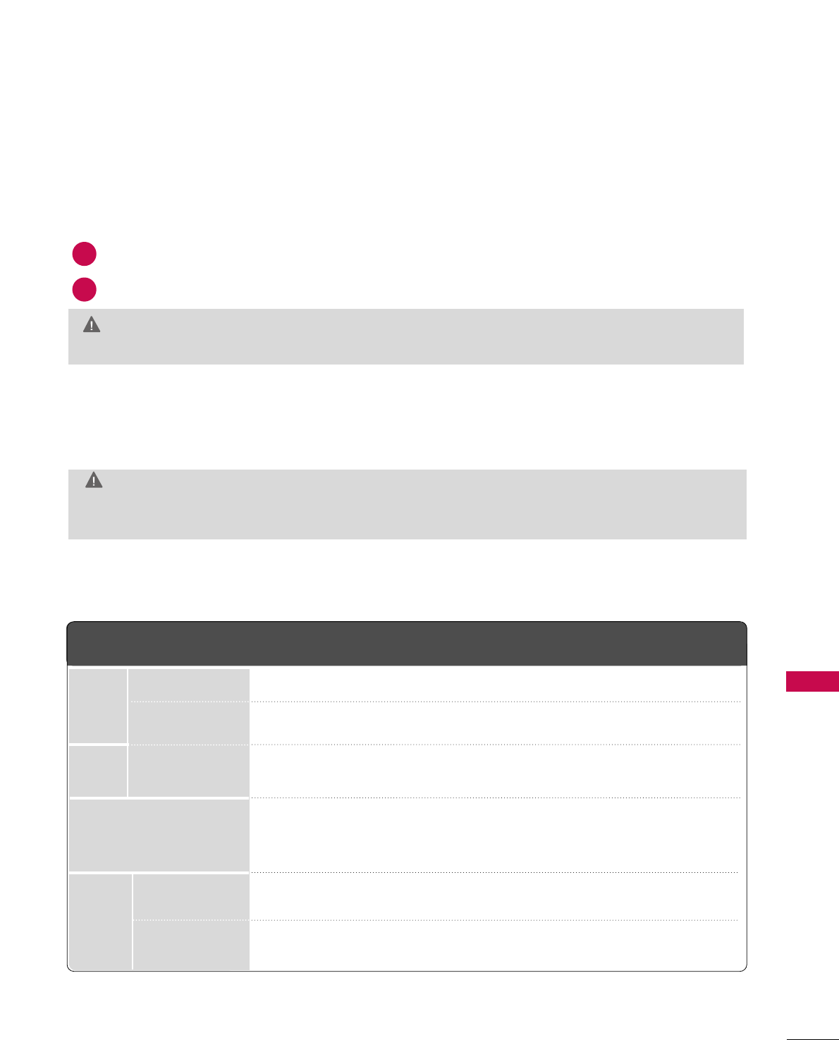
TThheerree iiss aa pprroobblleemm iinn PPCC mmooddee.. ((OOnnllyy PPCC mmooddee aapppplliieedd))
■Adjust resolution, horizontal frequency, or vertical frequency.
■Check the input source.
■Work the Auto configure or adjust clock, phase, or H/V position. (Option)
■Check the signal cable.
■Reinstall the PC video card.
The signal is out of range
Screen color is unstable
or single color
Vertical bar or stripe on
background &
Horizontal Noise &
Incorrect position
Picture OK & No sound
Unusual sound from
inside the product
No sound
when connecting HDMI
or USB
No output from one
of the speakers
TThhee aauuddiioo ddooeess nnoott wwoorrkk..
■Press the VOL or VOLUME button.
■Sound muted? Press MUTE button.
■Try another channel. The problem may be with the broadcast.
■Are the audio cables installed properly?
■Adjust Balance in menu option.
■A change in ambient humidity or temperature may result in an unusual noise
when the product is turned on or off and does not indicate a fault with the
product.
■Check HDMI cable over version 1.3.
■Check USB cable over version 2.0.
■Use normal MP3 file. *This feature is not available for all models.
APPENDIX
91
MAINTENANCE
■The specifications shown above may be changed without prior notice for quality improvement.
Early malfunctions can be prevented. Careful and regular cleaning can extend the amount of time you can
enjoy your new TV.
Caution: Be sure to turn the power off and unplug the power cord before you begin any cleaning.
Cleaning the Screen
Here’s a great way to keep the dust off your screen for a while. Wet a soft cloth in a mixture of lukewarm water and a
little fabric softener or dish washing detergent. Wring the cloth until it’s almost dry, and then use it to wipe the screen.
Make sure the excess water is off the screen, and then let it air-dry before you turn on your TV.
GG If you expect to leave your TV dormant for a long time (such as a vacation), it’s a good idea to unplug
the power cord to protect against possible damage from lightning or power surges.
CAUTION
2
1
GGDo not use window/glass cleaner or anything with ammonia to clean the screen.
WARNING
Cleaning the Cabinet
■To remove dirt or dust, wipe the cabinet with a soft, dry, lint-free cloth.
■Please be sure not to use a wet cloth.
Extended Absence
MODEL
AC100-240V ~ 50/60Hz
NTSC-M, ATSC, 64 & 256 QAM
VHF 2-13, UHF 14-69, CATV 1-135, DTV 2-69, CADTV 1-135
75 ohm
32 ~ 104°F (0 ~40°C)
Less than 80%
-4 ~ 140°F (-20 ~60°C)
Less than 85%
Dimensions
(Width
x Height
x Depth)
Weight
Power requirement
Television System
Program Coverage
External Antenna Impedance
Environment
condition
With stand
Without stand
With stand
Without stand
Operating Temperature
Operating Humidity
Storage Temperature
Storage Humidity
42LH250H (42LH250H-UA)
42LH255H (42LH255H-UA)
42LH260H (42LH260H-UA)
40.4 x 28.1 x 11.6 inches
1028.0 x 715.4 x 297.0 mm
40.4 x 25.7 x 3.4 inches
1028.0 x 655.0 x 88.7 mm
41.0 pounds / 18.6 kg
37.0 pounds / 16.8 kg
37LH250H (37LH250H-UA)
37LH255H (37LH255H-UA)
37LH260H (37LH260H-UA)
36.2 x 25.9 x 11.6 inches
922.0 x 659.0 x 297.0 mm
36.2 x 23.4 x 3.4 inches
922.0 x 595.0 x 88.0 mm
33.0 pounds / 15.0 kg
29.1 pounds / 13.2 kg
32LH240H (32LH240H-UA)
32LH250H (32LH250H-UA)
32LH255H (32LH255H-UA)
31.6 x 22.9 x 8.8 inches
805.0 x 583.0 x 223.8 mm
31.6 x 20.7 x 4.2 inches
805.0 x 528.2 x 108.9 mm
27.7 pounds / 12.6 kg
25.1 pounds / 11.4 kg
PRODUCT SPECIFICATIONS
APPENDIX
APPENDIX
92
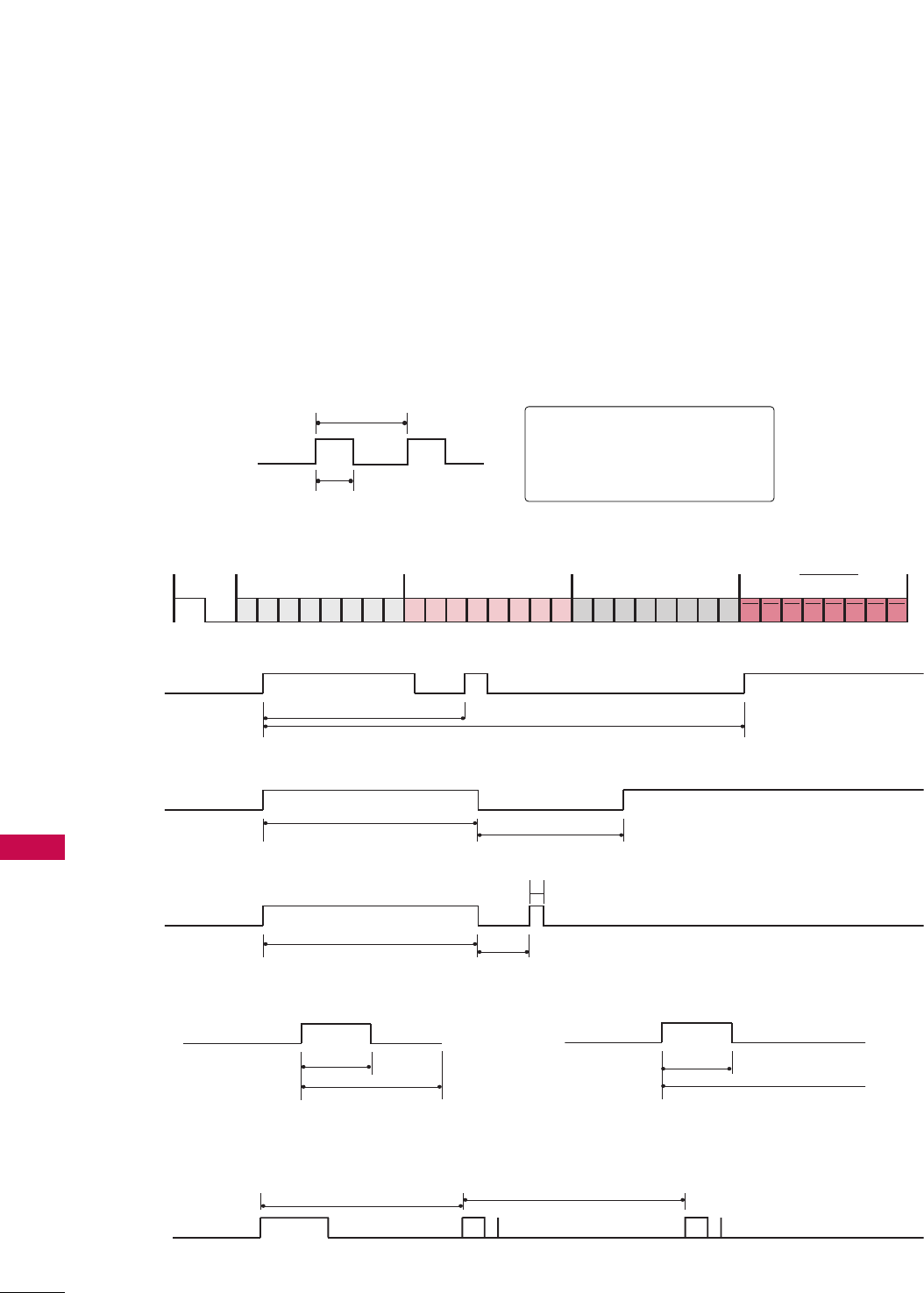
IR CODES
■
Configuration of frame
1st frame
Repeat frame
■
Lead code
■
Repeat code
■BBiitt ddeessccrriippttiioonn
■FFrraammee iinntteerrvvaall:: TTff
The waveform is transmitted as long as a key is depressed.
C0 C1 C2 C3 C4 C5 C6 C7 C0 C1 C2 C3 C4 C5 C6 C7 D0 D1 D2 D3 D4 D5 D6 D7 D0 D1 D2 D3 D4 D5 D6 D7
Lead code Low custom code High custom code Data code Data code
Repeat code Tf
4.5 ms
9 ms
2.25 ms
9 ms
0.55 ms
0.56 ms
1.12 ms
0.56 ms
2.24 ms
Tf Tf
Tf=108ms @455KHz
Bit ”0” Bit ”1”
1. How to Connect
■Connect your wired remote control to the Remote Control port on the TV.
2. Remote Control IR Codes
■
Output waveform
Single pulse, modulated with 37.917KHz signal at 455KHz
T1
Tc
Carrier frequency
FCAR = 1/TC = fOSC/12
Duty ratio = T1/TC = 1/3
APPENDIX
93
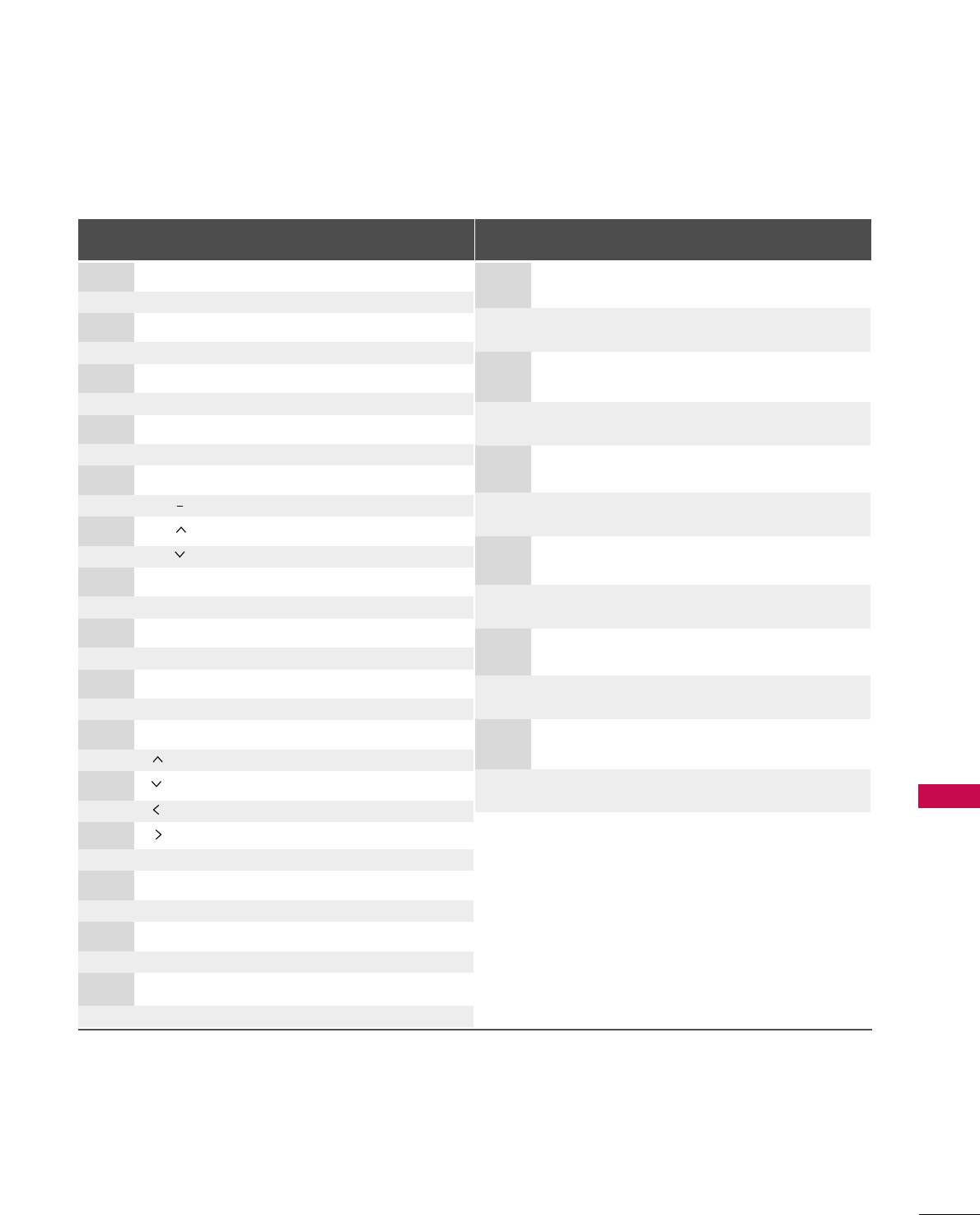
Code Function Note
(Hexa) Code Function Note
(Hexa)
D6 TV Discrete IR Code
(TV Input Selection)
5A AV1
Discrete IR Code
(AV1 Input Selection)
D0 AV2 Discrete IR Code
(AV2 Input Selection)
BF COMPONENT
Discrete IR Code
(
COMPONENT
Input Selection)
D5 RGB-PC
Discrete IR Code
(
RGB
Input Selection)
CE HDMI1
Discrete IR Code
(
HDMI1
Input Selection)
CC HDMI2 Discrete IR Code
(HDMI2 Input Selection)
76 Ratio 4:3
Discrete IR Code
(
Only 4:3 Mode
)
77 Ratio 16:9
Discrete IR Code
(
Only 16:9 Mode
)
AF Ratio Zoom
Discrete IR Code
(
Only Zoom1 Mode
)
C4 POWER ON
Discrete IR Code
(
Only Power On
)
C5 POWER OFF
Discrete IR Code
(
Only Power Off)
08 POWER
Remote control Button (Power On/Off)
0B INPUT Remote control Button
1E MARK Remote control Button
79 RATIO Remote control Button
39 CC Remote control Button
10-19 Number Key 0-9 Remote control Button
4C - (Dash)/LIST Remote control Button
1A FLASHBK Remote control Button
02 VOL + Remote control Button
03 VOL - Remote control Button
00 CH Remote control Button
01 CH Remote control Button
0A SAP Remote control Button
0E TIMER Remote control Button
09 MUTE Remote control Button
43 MENU Remote control Button
5B RETURN Remote control Button
E8 ALAM Remote control Button
CA EJECT Remote control Button
40 Remote control Button
41 Remote control Button
07 Remote control Button
06 Remote control Button
44 ENTER Remote control Button
72 RED Remote control Button
71 A (GREEN) Remote control Button
63 G (YELLOW) Remote control Button
61
ll ll
(BLUE) Remote control Button
8F FF Remote control Button
8E GG Remote control Button

94
OPEN SOURCE LICENSE
Copyright (C) 1989, 1991 Free Software Foundation, Inc., 51
Franklin Street, Fifth Floor, Boston, MA 02110-1301 USA
Everyone is permitted to copy and distribute verbatim copies of
this license document, but changing it is not allowed.
Preamble
The licenses for most software are designed to take away your
freedom to share and change it. By contrast, the GNU General
Public License is intended to guarantee your freedom to share
and change free software - to make sure the software is free for
all its users. This General Public License applies to most of the
Free Software Foundation's software and to any other program
whose authors commit to using it. (Some other free software
foundation software is covered by the GNU Lesser General Public
License instead.) You can apply it to your programs, too.
When we speak of free software, we are referring to freedom, not
price. Our General Public Licenses are designed to make sure that
you have the freedom to distribute copies of free software (and
charge for this service if you wish), that you receive source code
or can get it if you want it, that you can change the software or
use pieces of it in new free programs; and that you know you can
do these things.
To protect your rights, we need to make restrictions that forbid
anyone to deny you these rights or to ask you to surrender the
rights. These restrictions translate to certain responsibilities for
you if you distribute copies of the software, or if you modify it.
For example, if you distribute copies of such a program, whether
gratis or for a fee, you must give the recipients all the rights that
you have. You must make sure that they, too, receive or can get
the source code. And you must show them these terms so they
know their rights.
We protect your rights with two steps: (1) copyright the soft-
ware, and (2) offer you this license which gives you legal permis-
sion to copy, distribute and/or modify the software.
Also, for each author's protection and ours, we want to make cer-
tain that everyone understands that there is no warranty for this
free software. If the software is modified by someone else and
passed on, we want its recipients to know that what they have is
not the original, so that any problems introduced by others will
not reflect on the original authors' reputations.
Finally, any free program is threatened constantly by software
patents. We wish to avoid the danger that redistributors of a free
program will individually obtain patent licenses, in effect making
the program proprietary. To prevent this, we have made it clear
that any patent must be licensed for everyone's free use or not
licensed at all.
The precise terms and conditions for copying, distribution and
modification follow.
GNU GENERAL PUBLIC LICENSE
TERMS AND CONDITIONS FOR COPYING, DISTRIBUTION
AND MODIFICATION
0. This license applies to any program or other work which con-
tains a notice placed by the copyright holder saying it may be
distributed under the terms of this General Public License. The
"Program", below, refers to any such program or work, and a
"work based on the Program" means either the Program or any
derivative work under copyright law: that is to say, a work con-
taining the Program or a portion of it, either verbatim or with
modifications and/or translated into another language.
(Hereinafter, translation is included without limitation in the
term "modification".) Each licensee is addressed as "you".
Activities other than copying, distribution and modification
are not covered by this license; they are outside its scope.
The act of running the Program is not restricted, and the out-
put from the program is covered only if its contents constitute
a work based on the program (independent of having been
made by running the program). Whether that is true depends
on what the program does.
1. You may copy and distribute verbatim copies of the program's
source code as you receive it, in any medium, provided that
you conspicuously and appropriately publish on each copy an
appropriate copyright notice and disclaimer of warranty; keep
intact all the notices that refer to this license and to the
absence of any warranty; and give any other recipients of the
program a copy of this license along with the Program.
You may charge a fee for the physical act of transferring a
copy, and you may at your option offer warranty protection in
exchange for a fee.
2. You may modify your copy or copies of the program or any
portion of it, thus forming a work based on the Program, and
copy and distribute such modifications or work under the
terms of section 1 above, provided that you also meet all of
these conditions:
a) You must cause the modified files to carry prominent
notices stating that you changed the files and the date of
any change.
GNU GENERAL PUBLIC LICENSE
Version 2, June 1991

95
b) You must cause any work that you distribute or publish,
that in whole or in part contains or is derived from the
Program or any part there of, to be licensed as a whole at
no charge to all third parties under the terms of this
license.
c) If the modified program normally reads commands interac-
tively when run, you must cause it, when started running
for such interactive use in the most ordinary way, to print
or display an announcement including an appropriate
copyright notice and a notice that there is no warranty (or
else, saying that you provide a warranty) and that users
may redistribute the program under these conditions, and
telling the user how to view a copy of this license.
(Exception: if the Program itself is interactive but does not
normally print such an announcement, your work based on
the Program is not required to print an announcement.)
These requirements apply to the modified work as a whole. If
identifiable sections of that work are not derived from the
Program, and can be reasonably considered independent and
separate works in themselves, then this license, and its terms,
do not apply to those sections when you distribute them as
separate works. But when you distribute the same sections as
part of a whole which is a work based on the Program, the dis-
tribution of the whole must be on the terms of this license,
whose permissions for other licensees extend to the entire
whole, and thus to each and every part regardless of who
wrote it.
Thus, it is not the intent of this section to claim rights or con-
test your rights to work written entirely by you; rather, the
intent is to exercise the right to control the distribution of
derivative or collective works based on the program.
In addition, mere aggregation of another work not based on
the program with the Program (or with a work based on the
program) on a volume of a storage or distribution medium
does not bring the other work under the scope of this license.
3. You may copy and distribute the program (or a work based on
it, under section 2) in object code or executable form under
the terms of sections 1 and 2 above provided that you also
do one of the following:
a) Accompany it with the complete corresponding machine-
readable source code, which must be distributed under the
terms of sections 1 and 2 above on a medium customarily
used for software interchange; or,
b) Accompany it with a written offer, valid for at least three
years, to give any third party, for a charge no more than
your cost of physically performing source distribution, a
complete machine-readable copy of the corresponding
source code, to be distributed under the terms of sections
1 and 2 above on a medium customarily used for software
interchange; or,
c) Accompany it with the information you received as to the
offer to distribute corresponding source code. (This alter-
native is allowed only for noncommercial distribution and
only if you received the program in object code or exe-
cutable form with such an offer, in accord with Subsection
b above.)
The source code for a work means the preferred form of the
work for making modifications to it. For an executable work,
complete source code means all the source code for all mod-
ules it contains, plus any associated interface definition files,
plus the scripts used to control compilation and installation
of the executable. However, as a special exception, the source
code distributed need not include anything that is normally
distributed (in either source or binary form) with the major
components (compiler, kernel, and so on) of the operating
system on which the executable runs, unless that component
itself accompanies the executable.
If distribution of executable or object code is made by offer-
ing access to copy from a designated place, then offering
equivalent access to copy the source code from the same
place counts as distribution of the source code, even though
third parties are not compelled to copy the source along with
the object code.
4. You may not copy, modify, sublicense, or distribute the Program
except as expressly provided under this license. Any attempt
otherwise to copy, modify, sublicense or distribute the
Program is void, and will automatically terminate your rights
under this license. However, parties who have received copies,
or rights, from you under this license will not have their licens-
es terminated so long as such parties remain in full compli-
ance.
5. You are not required to accept this license, since you have not
signed it. However, nothing else grants you permission to
modify or distribute the Program or its derivative works.
These actions are prohibited by law if you do not accept this
license. Therefore, by modifying or distributing the program
(or any work based on the program), you indicate your accep-
tance of this license to do so, and all its terms and conditions
for copying, distributing or modifying the program or works
based on it.
6. Each time you redistribute the program (or any work based on
the Program), the recipient automatically receives a license
from the original licensor to copy, distribute or modify the
Program subject to these terms and conditions. You may not
impose any further restrictions on the recipients' exercise of
the rights granted herein. You are not responsible for enforc-
ing compliance by third parties to this license.

APPENDIX
APPENDIX
96
7. If, as a consequence of a court judgment or allegation of
patent infringement or for any other reason (not limited to
patent issues), conditions are imposed on you (whether by
court order, agreement or otherwise) that contradict the con-
ditions of this license, they do not excuse you from the con-
ditions of this license. If you cannot distribute so as to satis-
fy simultaneously your obligations under this license and any
other pertinent obligations, then as a consequence you may
not distribute the program at all. For example, if a patent
license would not permit royalty-free redistribution of the
program by all those who receive copies directly or indirectly
through you, then the only way you could satisfy both it and
this license would be to refrain entirely from distribution of
the program.
If any portion of this section is held invalid or unenforceable
under any particular circumstance, the balance of the section
is intended to apply and the section as a whole is intended to
apply in other circumstances.
It is not the purpose of this section to induce you to infringe
any patents or other property right claims or to contest valid-
ity of any such claims; this section has the sole purpose of
protecting the integrity of the free software distribution sys-
tem, which is implemented by public license practices. Many
people have made generous contributions to the wide range
of software distributed through that system in reliance on
consistent application of that system; it is up to the
author/donor to decide if he or she is willing to distribute
software through any other system and a licensee cannot
impose that choice.
This section is intended to make thoroughly clear what is
believed to be a consequence of the rest of this license.
8. If the distribution and/or use of the program is restricted in
certain countries either by patents or by copyrighted inter-
faces, the original copyright holder who places the program
under this license may add an explicit geographical distribution
limitation excluding those countries, so that distribution is
permitted only in or among countries not thus excluded. In
such case, this license incorporates the limitation as if written
in the body of this license.
9. The Free Software Foundation may publish revised and/or
new versions of the General Public License from time to time.
Such new versions will be similar in spirit to the present ver-
sion, but may differ in detail to address new problems or con-
cerns.
Each version is given a distinguishing version number. If the
program specifies a version number of this license which
applies to it and "any later version", you have the option of
following the terms and conditions either of that version or of
any later version published by the Free Software Foundation.
If the program does not specify a version number of this
license, you may choose any version ever published by the
Free Software Foundation.
10.If you wish to incorporate parts of the program into other free
programs whose distribution conditions are different, write to
the author to ask for permission. For software which is copy-
righted by the Free Software Foundation, write to the Free
Software Foundation; we sometimes make exceptions for this.
Our decision will be guided by the two goals of preserving the
free status of all derivatives of our free software and of pro-
moting the sharing and reuse of software generally.
NO WARRANTY
11. BECAUSE THE PROGRAM IS LICENSED FREE OF CHARGE,
THERE IS NO WARRANTY FOR THE PROGRAM, TO THE
EXTENT PERMITTED BY APPLICABLE LAW. EXCEPT WHEN
OTHERWISE STATED IN WRITING THE COPYRIGHT HOLD-
ERS AND/OR OTHER PARTIES PROVIDE THE PROGRAM "AS
IS" WITHOUT WARRANTY OF ANY KIND, EITHER
EXPRESSED OR IMPLIED, INCLUDING, BUT NOT LIMITED
TO, THE IMPLIED WARRANTIES OF MERCHANTABILITY
AND FITNESS FOR A PARTICULAR PURPOSE. THE ENTIRE
RISK AS TO THE QUALITY AND PERFORMANCE OF THE
PROGRAM IS WITH YOU. SHOULD THE PROGRAM PROVE
DEFECTIVE, YOU ASSUME THE COST OF ALL NECESSARY
SERVICING, REPAIR OR CORRECTION.
12.IN NO EVENT UNLESS REQUIRED BY APPLICABLE LAW OR
AGREED TO IN WRITING WILL ANY COPYRIGHT HOLDER,
OR ANY OTHER PARTY WHO MAY MODIFY AND/OR
REDISTRIBUTE THE PROGRAM AS PERMITTED ABOVE, BE
LIABLE TO YOU FOR DAMAGES, INCLUDING ANY GENERAL,
SPECIAL, INCIDENTAL OR CONSEQUENTIAL DAMAGES
ARISING OUT OF THE USE OR INABILITY TO USE THE PRO-
GRAM (INCLUDING BUT NOT LIMITED TO LOSS OF DATA
OR DATA BEING RENDERED INACCURATE OR LOSSES SUS-
TAINED BY YOU OR THIRD PARTIES OR A FAILURE OF THE
PROGRAM TO OPERATE WITH ANY OTHER PROGRAMS),
EVEN IF SUCH HOLDER OR OTHER PARTY HAS BEEN
ADVISED OF THE POSSIBILITY OF SUCH DAMAGES.

APPENDIX
97
END OF TERMS AND CONDITIONS
How to apply these terms to your new programs
If you develop a new program, and you want it to be of the great-
est possible use to the public, the best way to achieve this is to
make it free software which everyone can redistribute and change
under these terms.
To do so, attach the following notices to the program. It is safest
to attach them to the start of each source file to most effective-
ly convey the exclusion of warranty; and each file should have at
least the "copyright" line and a pointer to where the full notice is
found.
one line to give the program's name and a brief idea of what it
does.
Copyright (C) <year> <name of author>
This program is free software; you can redistribute it and/or
modify it under the terms of the GNU General Public License as
published by the Free Software Foundation; either version 2 of
the license, or (at your option) any later version.
This program is distributed in the hope that it will be useful, but
WITHOUT ANY WARRANTY; without even the implied warranty
of MERCHANTABILITY or FITNESS FOR A PARTICULAR PUR-
POSE. See the GNU General Public License for more details.
You should have received a copy of the GNU General Public
License along with this program; if not, write to the Free Software
Foundation, Inc., 51 Franklin Street, Fifth Floor, Boston, MA
02110-1301 USA.
Also add information on how to contact you by electronic and
paper mail.
If the program is interactive, make it output a short notice like
this when it starts in an interactive mode:
Gnomovision version 69, Copyright (C) year name of author
Gnomovision comes with ABSOLUTELY NO WARRANTY; for
details type ‘show w’. This is free software, and you are welcome
to redistribute it under certain conditions; type ‘show c’ for
details.
The hypothetical commands ‘show w’ and ‘show c’ should show
the appropriate parts of the General Public License. Of course,
the commands you use may be called something other than
‘show w’ and ‘show c’; they could even be mouse-clicks or menu
items-whatever suits your program.
You should also get your employer (if you work as a programmer)
or your school, if any, to sign a “copyright disclaimer” for the pro-
gram, if necessary. Here is a sample; alter the names:
Yoyodyne, Inc., hereby disclaims all copyright interest in the pro-
gram ‘Gnomovision’ (which makes passes at compilers) written by
James Hacker.
signature of Ty Coon, 1 April 1989
Ty Coon, President of Vice
This General Public License does not permit incorporating your
program into proprietary programs. If your program is a subrou-
tine library, you may consider it more useful to permit linking pro-
prietary applications with the library. If this is what you want to
do, use the GNU Lesser General Public License instead of this
license.

98
Copyright (C) 1991, 1999 Free Software Foundation, Inc. 51
Franklin Street, Fifth Floor, Boston, MA 02110-1301 USA
Everyone is permitted to copy and distribute verbatim copies of
this license document, but changing it is not allowed.
[This is the first released version of the Lesser GPL. It also
counts as the successor of the GNU Library Public License, ver-
sion 2, hence the version number 2.1.]
Preamble
The licenses for most software are designed to take away your
freedom to share and change it. By contrast, the GNU General
Public Licenses are intended to guarantee your freedom to share
and change free software - to make sure the software is free for
all its users.
This license, the Lesser General Public License, applies to some
specially designated software packages - typically libraries - of
the Free Software Foundation and other authors who decide to
use it. You can use it too, but we suggest you first think careful-
ly about whether this license or the ordinary General Public
License is the better strategy to use in any particular case, based
on the explanations below.
When we speak of free software, we are referring to freedom of
use, not price. Our General Public Licenses are designed to make
sure that you have the freedom to distribute copies of free soft-
ware (and charge for this service if you wish); that you receive
source code or can get it if you want it; that you can change the
software and use pieces of it in new free programs; and that you
are informed that you can do these things.
To protect your rights, we need to make restrictions that forbid
distributors to deny you these rights or to ask you to surrender
these rights. These restrictions translate to certain responsibilities
for you if you distribute copies of the library or if you modify it.
For example, if you distribute copies of the library, whether gratis
or for a fee, you must give the recipients all the rights that we
gave you. You must make sure that they, too, receive or can get
the source code. If you link other code with the library, you must
provide complete object files to the recipients, so that they can
relink them with the library after making changes to the library
and recompiling it. And you must show them these terms so they
know their rights.
We protect your rights with a two-step method: (1) we copyright
the library, and (2) we offer you this license, which gives you legal
permission to copy, distribute and/or modify the library.
To protect each distributor, we want to make it very clear that
there is no warranty for the free library. Also, if the library is mod-
ified by someone else and passed on, the recipients should know
that what they have is not the original version, so that the origi-
nal author's reputation will not be affected by problems that
might be introduced by others.
Finally, software patents pose a constant threat to the existence
of any free program. We wish to make sure that a company can-
not effectively restrict the users of a free program by obtaining a
restrictive license from a patent holder. Therefore, we insist that
any patent license obtained for a version of the library must be
consistent with the full freedom of use specified in this license.
Most GNU software, including some libraries, is covered by the
ordinary GNU General Public License. This license, the GNU
Lesser General Public License, applies to certain designated
libraries, and is quite different from the ordinary General Public
License. We use this license for certain libraries in order to per-
mit linking those libraries into non-free programs.
When a program is linked with a library, whether statically or
using a shared library, the combination of the two is legally
speaking a combined work, a derivative of the original library. The
ordinary General Public License therefore permits such linking
only if the entire combination fits its criteria of freedom. The
Lesser General Public License permits more lax criteria for linking
other code with the library.
We call this license the "Lesser" General Public License because
it does Less to protect the user's freedom than the ordinary
General Public License. It also provides other free software devel-
opers Less of an advantage over competing non-free programs.
These disadvantages are the reason we use the ordinary General
Public License for many libraries. However, the Lesser license pro-
vides advantages in certain special circumstances.
For example, on rare occasions, there may be a special need to
encourage the widest possible use of a certain library, so that it
becomes a de-facto standard. To achieve this, non-free programs
must be allowed to use the library. A more frequent case is that
a free library does the same job as widely used non-free libraries.
In this case, there is little to gain by limiting the free library to free
software only, so we use the Lesser General Public License.
In other cases, permission to use a particular library in non-free
programs enables a greater number of people to use a large body
of free software. For example, permission to use the GNU C
Library in non-free programs enables many more people to use
the whole GNU operating system, as well as its variant, the
GNU/Linux operating system.
GNU LESSER GENERAL PUBLIC LICENSE
Version 2.1, February 1999

99
Although the Lesser General Public License is Less protective of
the users' freedom, it does ensure that the user of a program that
is linked with the Library has the freedom and the wherewithal to
run that program using a modified version of the Library.
The precise terms and conditions for copying, distribution and
modification follow. Pay close attention to the difference between
a "work based on the library" and a "work that uses the library".
The former contains code derived from the library, whereas the
latter must be combined with the library in order to run.
GNU LESSER GENERAL PUBLIC LICENSE
TERMS AND CONDITIONS FOR COPYING, DISTRIBUTION
AND MODIFICATION
0. This license agreement applies to any software library or other
program which contains a notice placed by the copyright hold-
er or other authorized party saying it may be distributed
under the terms of this Lesser General Public License (also
called “this license”). Each license is addressed as "you".
A “library” means a collection of software functions and/or
data prepared so as to be conveniently linked with application
programs (which use some of those functions and data) to
form executables.
The “Library”, below, refers to any such software library or work
which has been distributed under these terms. A “work based
on the Library” means either the Library or any derivative work
under copyright law: that is to say, a work containing the
library or a portion of it, either verbatim or with modifications
and/or translated straightforwardly into another language.
(Hereinafter, translation is included without limitation in the
term “modification”.)
“Source code” for a work means the preferred form of the
work for making modifications to it. For a library, complete
source code means all the source code for all modules it con-
tains, plus any associated interface definition files, plus the
scripts used to control compilation and installation of the
library.
Activities other than copying, distribution and modification
are not covered by this license; they are outside its scope.
The act of running a program using the Library is not restrict-
ed, and output from such a program is covered only if its con-
tents constitute a work based on the library (independent of
the use of the Library in a tool for writing it). Whether that is
true depends on what the library does and what the program
that uses the library does.
1. You may copy and distribute verbatim copies of the library's
complete source code as you receive it, in any medium, pro-
vided that you conspicuously and appropriately publish on
each copy an appropriate copyright notice and disclaimer of
warranty; keep intact all the notices that refer to this license
and to the absence of any warranty; and distribute a copy of
this license along with the Library.
You may charge a fee for the physical act of transferring a
copy, and you may at your option offer warranty protection in
exchange for a fee.
2. You may modify your copy or copies of the Library or any
portion of it, thus forming a work based on the Library, and
copy and distribute such modifications or work under the
terms of section 1 above, provided that you also meet all of
these conditions:
a) The modified work must itself be a software library.
b) You must cause the files modified to carry prominent
notices stating that you changed the files and the date of
any change.
c) You must cause the whole of the work to be licensed at no
charge to all third parties under the terms of this license.
d) If a facility in the modified Library refers to a function or a
table of data to be supplied by an application program that
uses the facility, other than as an argument passed when
the facility is invoked, then you must make a good faith
effort to ensure that, in the event an application does not
supply such function or table, the facility still operates, and
performs whatever part of its purpose remains meaningful.
(For example, a function in a library to compute square roots
has a purpose that is entirely well-defined independent of the
application. Therefore, Subsection 2d requires that any appli-
cation-supplied function or table used by this function must be
optional: if the application does not supply it, the square root
function must still compute square roots.)
These requirements apply to the modified work as a whole. If
identifiable sections of that work are not derived from the
library, and can be reasonably considered independent and
separate works in themselves, then this license, and its terms,
do not apply to those sections when you distribute them as
separate works. But when you distribute the same sections as
part of a whole which is a work based on the library, the dis-
tribution of the whole must be on the terms of this license,
whose permissions for other licenses extend to the entire
whole, and thus to each and every part regardless of who
wrote it.
Thus, it is not the intent of this section to claim rights or con-
test your rights to work written entirely by you; rather, the
intent is to exercise the right to control the distribution of
derivative or collective works based on the library.
In addition, mere aggregation of another work not based on
the library with the library (or with a work based on the
library) on a volume of a storage or distribution medium does
not bring the other work under the scope of this license.

100
3. You may opt to apply the terms of the ordinary GNU General
Public License instead of this License to a given copy of the
Library. To do this, you must alter all the notices that refer to
this License, so that they refer to the ordinary GNU General
Public License, version 2, instead of to this License. (If a newer
version than version 2 of the ordinary GNU General Public
License has appeared, then you can specify that version
instead if you wish.) Do not make any other change in these
notices.
Once this change is made in a given copy, it is irreversible for
that copy, so the ordinary GNU General Public License applies
to all subsequent copies and derivative works made from that
copy.
This option is useful when you wish to copy part of the code
of the library into a program that is not a library.
4. You may copy and distribute the library (or a portion or deriv-
ative of it, under Section 2) in object code or executable form
under the terms of Sections 1 and 2 above provided that you
accompany it with the complete corresponding machine-
readable source code, which must be distributed under the
terms of sections 1 and 2 above on a medium customarily
used for software interchange.
If distribution of object code is made by offering access to
copy from a designated place, then offering equivalent access
to copy the source code from the same place satisfies the
requirement to distribute the source code, even though third
parties are not compelled to copy the source along with the
object code.
5. A program that contains no derivative of any portion of the
Library, but is designed to work with the Library by being
compiled or linked with it, is called a “work that uses the
Library”. Such a work, in isolation, is not a derivative work of
the Library, and therefore falls outside the scope of this
license.
However, linking a “work that uses the library” with the Library
creates an executable that is a derivative of the Library
(because it contains portions of the library), rather than a
“work that uses the library”. The executable is therefore cov-
ered by this license. Section 6 states terms for distribution of
such executable.
When a “work that uses the library” uses material from a head-
er file that is part of the library, the object code for the work
may be a derivative work of the library even though the source
code is not.
Whether this is true is especially significant if the work can be
linked without the library, or if the work is itself a library. The
threshold for this to be true is not precisely defined by law.
If such an object file uses only numerical parameters, data
structure layouts and accessories, and small macros and small
inline functions (ten lines or less in length), then the use of
the object file is unrestricted, regardless of whether it is legal-
ly a derivative work. (Executable containing this object code
plus portions of the library will still fall under Section 6.)
Otherwise, if the work is a derivative of the library, you may
distribute the object code for the work under the terms of
Section 6. Any executable containing that work also fall under
Section 6, whether or not they are linked directly with the
library itself.
6. As an exception to the sections above, you may also combine
or link a "work that uses the library" with the library to pro-
duce a work containing portions of the library, and distribute
that work under terms of your choice, provided that the terms
permit modification of the work for the customer's own use
and reverse engineering for debugging such modifications.
You must give prominent notice with each copy of the work
that the library is used in it and that the Library and its use
are covered by this license. You must supply a copy of this
license. If the work during execution displays copyright
notices, you must include the copyright notice for the library
among them, as well as a reference directing the user to the
copy of this license. Also, you must do one of these things:
a) Accompany the work with the complete corresponding
machine-readable source code for the library including
whatever changes were used in the work (which must be
distributed under Sections 1 and 2 above); and, if the work
is an executable linked with the Library, with the complete
machine-readable “work that uses the Library”, as object
code and/or source code, so that the user can modify the
library and then relink to produce a modified executable
containing the modified library. (It is understood that the
user who changes the contents of definitions files in the
library will not necessarily be able to recompile the appli-
cation to use the modified definitions.)
b) Use a suitable shared library mechanism for linking with the
library. A suitable mechanism is one that (1) uses at run time
a copy of the library already present on the user’s computer
system, rather than copying library functions into the exe-
cutable, and (2) will operate properly with a modified version
of the library, if the user installs one, as long as the modified
version is interface-compatible with the version that the
work was made with.
c) Accompany the work with a written offer, valid for at least
three years, to give the same user the materials specified in
Subsection 6, above, for a charge no more than the cost of
performing this distribution.
d) If distribution of the work is made by offering access to
copy from a designated place, offer equivalent access to
copy the above specified materials from the same place.
e) Verify that the user has already received a copy of these
materials or that you have already sent this user a copy.

101
For an executable, the required form of the "work that uses
the library" must include any data and utility programs need-
ed for reproducing the executable from it. However, as a spe-
cial exception, the materials to be distributed need not
include anything that is normally distributed (in either source
or binary form) with the major components (compiler, kernel,
and so on) of the operating system on which the executable
runs, unless that component itself accompanies the exe-
cutable.
It may happen that this requirement contradicts the license
restrictions of other proprietary libraries that do not normal-
ly accompany the operating system. Such a contradiction
means you cannot use both them and the library together in
an executable that you distribute.
7. You may place library facilities that are a work based on the
library side-by-side in a single library together with other
library facilities not covered by this license, and distribute
such a combined library, provided that the separate distribu-
tion of the work based on the Library and of the other library
facilities is otherwise permitted, and provided that you do
these two things:
a) Accompany the combined library with a copy of the same
work based on the Library, uncombined with any other
library facilities. This must be distributed under the terms
of the sections above.
b) Give prominent notice with the combined library of the
fact that part of it is a work based on the library, and
explaining where to find the accompanying uncombined
form of the same work.
8. You may not copy, modify, sublicense, link with, or distribute
the library except as expressly provided under this license.
Any attempt otherwise to copy, modify, sublicense, link with,
or distribute the library is void, and will automatically termi-
nate your rights under this license. However, parties who have
received copies, or rights, from you under this license will not
have their licenses terminated so long as such parties remain
in full compliance.
9. You are not required to accept this license, since you have not
signed it. However, nothing else grants you permission to mod-
ify or distribute the library or its derivative works. These
actions are prohibited by law if you do not accept this license.
Therefore, by modifying or distributing the library (or any work
based on the library), you indicate your acceptance of this
license to do so, and all its terms and conditions for copying,
distributing or modifying the library or works based on it.
10.Each time you redistribute the library (or any work based on
the Library), the recipient automatically receives a license
from the original licensor to copy, distribute, link with or mod-
ify the library subject to these terms and conditions. You may
not impose any further restrictions on the recipients' exercise
of the rights granted herein.
You are not responsible for enforcing compliance by third
parties with this license.
11. If, as a consequence of a court judgment or allegation of
patent infringement or for any other reason (not limited to
patent issues), conditions are imposed on you (whether by
court order, agreement or otherwise) that contradict the con-
ditions of this license, they do not excuse you from the con-
ditions of this license. If you cannot distribute so as to satis-
fy simultaneously your obligations under this license and any
other pertinent obligations, then as a consequence you may
not distribute the library at all. For example, if a patent license
would not permit royalty-free redistribution of the library by
all those who receive copies directly or indirectly through
you, then the only way you could satisfy both it and this
license would be to refrain entirely from distribution of the
library.
If any portion of this section is held invalid or unenforceable
under any particular circumstance, the balance of the section
is intended to apply, and the section as a whole is intended to
apply in other circumstances.
It is not the purpose of this section to induce you to infringe
any patents or other property right claims or to contest valid-
ity of any such claims; this section has the sole purpose of
protecting the integrity of the free software distribution sys-
tem which is implemented by public license practices. Many
people have made generous contributions to the wide range
of software distributed through that system in reliance on
consistent application of that system; it is up to the
author/donor to decide if he or she is willing to distribute
software through any other system and a license cannot
impose that choice.
This section is intended to make thoroughly clear what is
believed to be a consequence of the rest of this license.
12.If the distribution and/or use of the library is restricted in cer-
tain countries either by patents or by copyrighted interfaces,
the original copyright holder who places the library under this
license may add an explicit geographical distribution limitation
excluding those countries, so that distribution is permitted
only in or among countries not thus excluded. In such case,
this license incorporates the limitation as if written in the body
of this license.
13.The Free Software Foundation may publish revised and/or
new versions of the Lesser General Public License from time to
time. Such new versions will be similar in spirit to the present
version, but may differ in detail to address new problems or
concerns.
Each version is given a distinguishing version number. If the
library specifies a version number of this license which applies
to it and “any later version”, you have the option of following
the terms and conditions either of that version or of any later
version published by the Free Software Foundation.

102
If the library does not specify a license version number, you
may choose any version ever published by the Free Software
Foundation.
14.If you wish to incorporate parts of the library into other free
programs whose distribution conditions are incompatible with
these, write to the author to ask for permission. For software
which is copyrighted by the Free Software Foundation, write
to the Free Software Foundation; we sometimes make excep-
tions for this. Our decision will be guided by the two goals of
preserving the free status of all derivatives of our free software
and of promoting the sharing and reuse of software generally.
NO WARRANTY
15.BECAUSE THE LIBRARY IS LICENSED FREE OF CHARGE,
THERE IS NO WARRANTY FOR THE LIBRARY, TO THE
EXTENT PERMITTED BY APPLICABLE LAW. EXCEPT WHEN
OTHERWISE STATED IN WRITING THE COPYRIGHT HOLD-
ERS AND/OR OTHER PARTIES PROVIDE THE LIBRARY "AS
IS" WITHOUT WARRANTY OF ANY KIND, EITHER
EXPRESSED OR IMPLIED, INCLUDING, BUT NOT LIMITED
TO, THE IMPLIED WARRANTIES OF MERCHANTABILITY
AND FITNESS FOR A PARTICULAR PURPOSE. THE ENTIRE
RISK AS TO THE QUALITY AND PERFORMANCE OF THE
LIBRARY IS WITH YOU. SHOULD THE LIBRARY PROVE
DEFECTIVE, YOU ASSUME THE COST OF ALL NECESSARY
SERVICING, REPAIR OR CORRECTION.
16.IN NO EVENT UNLESS REQUIRED BY APPLICABLE LAW OR
AGREED TO IN WRITING WILL ANY COPYRIGHT HOLDER,
OR ANY OTHER PARTY WHO MAY MODIFY AND/OR
REDISTRIBUTE THE LIBRARY AS PERMITTED ABOVE, BE
LIABLE TO YOU FOR DAMAGES, INCLUDING ANY GENERAL,
SPECIAL, INCIDENTAL OR CONSEQUENTIAL DAMAGES
ARISING OUT OF THE USE OR INABILITY TO USE THE
LIBRARY (INCLUDING BUT NOT LIMITED TO LOSS OF DATA
OR DATA BEING RENDERED INACCURATE OR LOSSES SUS-
TAINED BY YOU OR THIRD PARTIES OR A FAILURE OF THE
LIBRARY TO OPERATE WITH ANY OTHER SOFTWARE),
EVEN IF SUCH HOLDER OR OTHER PARTY HAS BEEN
ADVISED OF THE POSSIBILITY OF SUCH DAMAGES.
END OF TERMS AND CONDITIONS
How to apply these terms to your new libraries
If you develop a new library, and you want it to be of the great-
est possible use to the public, we recommend making it free soft-
ware that everyone can redistribute and change. You can do so
by permitting redistribution under these terms (or, alternatively,
under the terms of the ordinary General Public License).
To apply these terms, attach the following notices to the library.
It is safest to attach them to the start of each source file to most
effectively convey the exclusion of warranty; and each file should
have at least the “copyright” line and a pointer to where the full
notice is found.
one line to give the library's name and a brief idea of what it does.
Copyright (C) <year> <name of author>
This library is free software; you can redistribute it and/or modify
it under the terms of the GNU Lesser General Public License as
published by the Free Software Foundation; either version 2.1 of
the license, or (at your option) any later version.
This library is distributed in the hope that it will be useful, but
WITHOUT ANY WARRANTY; without even the implied warranty
of MERCHANTABILITY or FITNESS FOR A PARTICULAR PUR-
POSE. See the GNU Lesser General Public License for more
details.
You should have received a copy of the GNU Lesser General
Public License along with this library; if not, write to the Free
Software Foundation, Inc., 51 Franklin Street, Fifth Floor, Boston,
MA 02110-1301 USA
Also add information on how to contact you by electronic and
paper mail.
You should also get your employer (if you work as a programmer)
or your school, if any, to sign a “copyright disclaimer” for the
library, if necessary. Here is a sample; alter the names:
Yoyodyne, Inc., hereby disclaims all copyright interest in the
library ‘Frob’ (a library for tweaking knobs) written by James
Random Hacker.
signature of Ty Coon, 1 April 1990
Ty Coon, President of Vice

103
1.Definitions.
1.0.1. “Commercial use” means distribution or otherwise making
the covered code available to a third party.
1.1. “Contributor” means each entity that creates or con-
tributes to the creation of modifications.
1.2. “Contributor version” means the combination of the orig-
inal code, prior modifications used by a contributor, and
the modifications made by that particular contributor.
1.3. “Covered code” means the original code or modifications
or the combination of the original code and modifications,
in each case including portions thereof.
1.4. “Electronic distribution mechanism” means a mechanism
generally accepted in the software development communi-
ty for the electronic transfer of data.
1.5. “Executable” means covered code in any form other than
source code.
1.6. “Initial developer” means the individual or entity identified
as the initial Developer in the Source Code notice required
by exhibit A.
1.7. “Larger work” means a work which combines covered code
or portions thereof with code not governed by the terms
of this License.
1.8. “License” means this document.
1.8.1. “Licensable” means having the right to grant, to the maxi-
mum extent possible, whether at the time of the initial
grant or subsequently acquired, any and all of the rights
conveyed herein.
1.9. “Modifications” means any addition to or deletion from
the substance or structure of either the original code or
any previous modifications. When covered code is
released as a series of files, a modification is:
A. Any addition to or deletion from the contents of a file
containing original code or previous modifications.
B. Any new file that contains any part of the original code
or previous modifications.
1.10. “Original code” means source code of computer software
code which is described in the source code notice
required by exhibit as original code, and which, at the time
of its release under this license is not already covered
code governed by this license.
1.10.1.
“Patent claims” means any patent claim(s), now owned or
hereafter acquired, including without limitation, method,
process, and apparatus claims, in any patent licensable by
grantor.
1.11. “Source code” means the preferred form of the covered
code for making modifications to it, including all modules
it contains, plus any associated interface definition files,
scripts used to control compilation and installation of an
executable, or source code differential comparisons
against either the original code or another well known,
available covered code of the contributor's choice. The
source code can be in a compressed or archival form, pro-
vided the appropriate decompression or de-archiving soft-
ware is widely available for no charge.
1.12. “You” (or “Your”) means an individual or a legal entity
exercising rights under, and complying with all of the terms
of, this license or a future version of this license issued
under section 6.1.
For legal entities, “You” includes any entity which controls,
is controlled by, or is under common control with You. For
purposes of this definition, “control” means (a) the power,
direct or indirect, to cause the direction or management of
such entity, whether by contract or otherwise, or (b) own-
ership of more than fifty percent (50%) of the outstand-
ing shares or beneficial ownership of such entity.
2. Source Code License.
2.1. The initial developer grant.
The initial developer hereby grants You a world-wide, roy-
alty-free, non-exclusive license, subject to third party intel-
lectual property claims:
a) under intellectual property rights (other than patent or
trademark) licensable by initial developer to use, repro-
duce, modify, display, perform, sublicense and distrib-
ute the original code (or portions thereof) with or with-
out modifications, and/or as part of a larger work; and
(b) under patents claims infringed by the making, using or
selling of original code, to make, have made, use, prac-
tice, sell, and offer for sale, and/or otherwise dispose
of the original code (or portions there of).
MOZILLA PUBLIC LICENSE
Version 1.1
---------------

104
(c) the licenses granted in this section 2.1(a) and (b) are
effective on the date Initial developer first distributes
original code under the terms of this license.
(d) Notwithstanding section 2.1(b) above, no patent
license is granted: 1) for code that You delete from the
original Code; 2) separate from the original code; or
3) for infringements caused by: i) the modification of
the original code or ii) the combination of the original
code with other software or devices.
2.2. Contributor Grant.
Subject to third party intellectual property claims, each
contributor hereby grants You a world-wide, royalty-free,
non-exclusive license
(a) under intellectual property rights (other than patent
or trademark) licensable by contributor, to use,
reproduce, modify, display, perform, sublicense and
distribute the modifications created by such contribu-
tor (or portions thereof) either on an unmodified
basis, with other modifications, as covered code
and/or as part of a larger work; and
(b) under patent claims infringed by the making, using, or
selling of modifications made by that contributor
either alone and/or in combination with its contributor
version (or portions of such combination), to make,
use, sell, offer for sale, have made, and/or otherwise
dispose of: 1) modifications made by that contributor
(or portions thereof); and 2) the combination of mod-
ifications made by that contributor with its contributor
version (or portions of such combination).
(c) the licenses granted in sections 2.2(a) and 2.2(b) are
effective on the date contributor first makes commer-
cial use of the covered code.
(d) Notwithstanding section 2.2(b) above, no patent
license is granted: 1) for any code that contributor has
deleted from the contributor version; 2) separate from
the contributor version; 3) for infringements caused
by: i) third party modifications of contributor version
or ii) the combination of modifications made by that
contributor with other software (except as part of the
contributor version) or other devices; or 4) under
patent claims infringed by covered code in the
absence of modifications made by that contributor.
3. Distribution Obligations.
3.1. Application of license.
The modifications which You create or to which you con-
tribute are governed by the terms of this license, including
without limitation section 2.2. The source code version of
covered code may be distributed only under the terms of
this license or a future version of this license released
under section 6.1, and you must include a copy of this
license with every copy of the source code you distribute.
You may not offer or impose any terms on any source code
version that alters or restricts the applicable version of
this license or the recipients' rights hereunder. However,
you may include an additional document offering the
additional rights described in section 3.5.
3.2. Availability of source code.
Any modification which you create or to which you con-
tribute must be made available in source code form under
the terms of this license either on the same media as an
executable version or via an accepted electronic distribu-
tion mechanism to anyone to whom you made an exe-
cutable version available; and if made available via elec-
tronic distribution mechanism, must remain available for at
least twelve (12) months after the date it initially became
available, or at least six (6) months after a subsequent
version of that particular modification has been made
available to such recipients. You are responsible for ensur-
ing that the source code version remains available even if
the electronic distribution mechanism is maintained by a
third party.
3.3. Description of modifications.
You must cause all covered code to which you contribute to
contain a file documenting the changes You made to create
that covered code and the date of any change. You must
include a prominent statement that the modification is
derived, directly or indirectly, from original code provided by
the initial developer and including the name of the initial
developer in (a) the source code, and (b) in any notice in an
executable version or related documentation in which you
describe the origin or ownership of the covered code.
3.4. Intellectual property matters
(a) Third party claims.
If contributor has knowledge that a license under a third
party's intellectual property rights is required to exercise
the rights granted by such contributor under sections 2.1
or 2.2, contributor must include a text file with the source
code distribution titled "LEGAL" which describes the claim
and the party making the claim in sufficient detail that a
recipient will know whom to contact. If contributor obtains
such knowledge after the modification is made available as
described in section 3.2, contributor shall promptly modi-
fy the LEGAL file in all copies contributor makes available
thereafter and shall take other steps (such as notifying
appropriate mailing lists or newsgroups) reasonably calcu-
lated to inform those who received the covered code that
new knowledge has been obtained.
(b) Contributor APIs.
If contributor's modifications include an application
programming interface and contributor has knowledge of
patent licenses which are reasonably necessary to implement
that API, contributor must also include this information in
the LEGAL file.

105
(c) Representations.
contributor represents that, except as disclosed pursuant
to section 3.4(a) above, contributor believes that contributor's
modifications are contributor's original creation(s)
and/or contributor has sufficient rights to grant the rights
conveyed by this license.
3.5. Required notices.
You must duplicate the notice in exhibit A in each file of
the source code. If it is not possible to put such notice in
a particular source code file due to its structure, then You
must include such notice in a location (such as a relevant
directory) where a user would be likely to look for such a
notice. If You created one or more modification(s), you
may add your name as a contributor to the notice
described in exhibit A. you must also duplicate this license
in any documentation for the source code where You
describe recipients' rights or ownership rights relating to
covered code. You may choose to offer, and to charge a
fee for, warranty, support, indemnity or liability obligations
to one or more recipients of covered code. However, you
may do so only on your own behalf, and not on behalf of
the Initial developer or any contributor. You must make it
absolutely clear than any such warranty, support, indemni-
ty or liability obligation is offered by you alone, and You
hereby agree to indemnify the Initial developer and every
contributor for any liability incurred by the Initial develop-
er or such contributor as a result of warranty, support,
indemnity or liability terms you offer.
3.6. Distribution of executable versions.
You may distribute covered code in executable form only if
the requirements of section 3.1-3.5 have been met for
that covered code, and if you include a notice stating that
the source code version of the covered code is available
under the terms of this license, including a description of
how and where you have fulfilled the obligations of section
3.2. The notice must be conspicuously included in any
notice in an executable version, related documentation or
collateral in which you describe recipients' rights relating
to the covered code. You may distribute the executable
version of covered code or ownership rights under a
license of your choice, which may contain terms different
from this license, provided that you are in compliance with
the terms of this license and that the license for the exe-
cutable version does not attempt to limit or alter the recip-
ient's rights in the source code version from the rights set
forth in this license. If you distribute the executable ver-
sion under a different license you must make it absolutely
clear that any terms which differ from this license are
offered by you alone, not by the Initial developer or any
contributor. You hereby agree to indemnify the initial
developer and every contributor for any liability incurred
by the initial developer or such contributor as a result of
any such terms You offer.
3.7. Larger works.
You may create a larger work by combining covered code
with other code not governed by the terms of this license
and distribute the larger work as a single product. In such
a case, you must make sure the requirements of this
license are fulfilled for the covered code.
4. Inability to comply due to statute or regulation.
If it is impossible for you to comply with any of the terms
of this license with respect to some or all of the covered
code due to statute, judicial order, or regulation then you
must: (a) comply with the terms of this license to the max-
imum extent possible; and (b) describe the limitations and
the code they affect. Such description must be included in
the LEGAL file described in section 3.4 and must be
included with all distributions of the source code. Except
to the extent prohibited by statute or regulation, such
description must be sufficiently detailed for a recipient of
ordinary skill to be able to understand it.
5. Application of this license.
This license applies to code to which the initial developer has
attached the notice in exhibit A and to related covered code.
6. Versions of the license.
6.1. New versions.
Netscape communications corporation (“Netscape”) may
publish revised and/or new versions of the license from
time to time. Each version will be given a distinguishing
version number.
6.2. Effect of new versions.
Once covered code has been published under a particular
version of the license, you may always continue to use it
under the terms of that version. You may also choose to
use such covered code under the terms of any subsequent
version of the license published by netscape. No one
other than netscape has the right to modify the terms
applicable to covered code created under this license.
6.3. Derivative works.
If You create or use a modified version of this license
(which you may only do in order to apply it to code which
is not already covered code governed by this license), You
must (a) rename Your license so that the phrases
"Mozilla", "MOZILLAPL", "MOZPL", "Netscape", "MPL",
"NPL" or any confusingly similar phrase do not appear in
your license (except to note that your license differs from
this license) and (b) otherwise make it clear that Your
version of the license contains terms which differ from the
Mozilla Public license and netscape Public License. (Filling
in the name of the initial developer, original code or con-
tributor in the notice described in exhibit A shall not of
themselves be deemed to be modifications of this license.)

106
7. DISCLAIMER OF WARRANTY.
COVERED CODE IS PROVIDED UNDER THIS LICENSE
ON AN “AS IS” BASIS, WITHOUT WARRANTY OF ANY
KIND, EITHER EXPRESSED OR IMPLIED, INCLUDING,
WITHOUT LIMITATION, WARRANTIES THAT THE COV-
ERED CODE IS FREE OF DEFECTS, MERCHANTABLE, FIT
FOR A PARTICULAR PURPOSE OR NON-INFRINGING.
THE ENTIRE RISK AS TO THE QUALITY AND PERFOR-
MANCE OF THE COVERED CODE IS WITH YOU.
SHOULD ANY COVERED CODE PROVE DEFECTIVE IN
ANY RESPECT, YOU (NOT THE INITIAL DEVELOPER OR
ANY OTHER CONTRIBUTOR) ASSUME THE COST OF
ANY NECESSARY SERVICING, REPAIR OR CORRECTION.
THIS DISCLAIMER OF WARRANTY CONSTITUTES AN
ESSENTIAL PART OF THIS LICENSE. NO USE OF ANY
COVERED CODE IS AUTHORIZED HEREUNDER EXCEPT
UNDER THIS DISCLAIMER.
8. TERMINATION.
8.1. This license and the rights granted hereunder will terminate
automatically if you fail to comply with terms herein and
fail to cure such breach within 30 days of becoming aware
of the breach. All sublicenses to the covered code which
are properly granted shall survive any termination of this
license. Provisions which, by their nature, must remain in
effect beyond the termination of this license shall survive.
8.2. If you initiate litigation by asserting a patent infringement
claim (excluding declatory judgment actions) against ini-
tial developer or a contributor (the initial developer or
contributor against whom you file such action is referred
to as “Participant”) alleging that:
(a) such participant's contributor version directly or indi-
rectly infringes any patent, then any and all rights
granted by such participant to you under sections 2.1
and/or 2.2 of this license shall, upon 60 days notice
from Participant terminate prospectively, unless if within
60 days after receipt of notice you either: (i) agree in
writing to pay participant a mutually agreeable reasonable
royalty for your past and future use of modifications
made by such participant, or (ii) withdraw your litigation
claim with respect to the contributor version against
such participant. If within 60 days of notice, a reasonable
royalty and payment arrangement are not mutually
agreed upon in writing by the parties or the litigation
claim is not withdrawn, the rights granted by partici-
pant to you under sections 2.1 and/or 2.2 automati-
cally terminate at the expiration of the 60 day notice
period specified above.
(b) any software, hardware, or device, other than such par-
ticipant's contributor Version, directly or indirectly
infringes any patent, then any rights granted to You by
such participant under sections 2.1(b) and 2.2(b) are
revoked effective as of the date you first made, used,
sold, distributed, or had made, modifications made by
that participant.
8.3. If you assert a patent infringement claim against partici-
pant alleging that such participant's contributor version
directly or indirectly infringes any patent where such claim
is resolved (such as by license or settlement) prior to the
initiation of patent infringement litigation, then the rea-
sonable value of the licenses granted by such participant
under sections 2.1 or 2.2 shall be taken into account in
determining the amount or value of any payment or
license.
8.4. In the event of termination under sections 8.1 or 8.2
above, all end user license agreements (excluding distributors
and resellers) which have been validly granted by you or
any distributor hereunder prior to termination shall survive
termination.
9. LIMITATION OF LIABILITY.
UNDER NO CIRCUMSTANCES AND UNDER NO LEGAL
THEORY, WHETHER TORT (INCLUDING NEGLIGENCE),
CONTRACT, OR OTHERWISE, SHALL YOU, THE INITIAL
DEVELOPER, ANY OTHER CONTRIBUTOR, OR ANY DIS-
TRIBUTOR OF COVERED CODE,OR ANY SUPPLIER OF
ANY OF SUCH PARTIES, BE LIABLE TO ANY PERSON FOR
ANY INDIRECT, SPECIAL, INCIDENTAL, OR CONSEQUEN-
TIAL DAMAGES OF ANY CHARACTER INCLUDING, WITH-
OUT LIMITATION, DAMAGES FOR LOSS OF GOODWILL,
WORK STOPPAGE, COMPUTER FAILURE OR MALFUNC-
TION, OR ANY AND ALL OTHER COMMERCIAL DAM-
AGES OR LOSSES, EVEN IF SUCH PARTY SHALL HAVE
BEEN INFORMED OF THE POSSIBILITY OF SUCH DAM-
AGES. THIS LIMITATION OF LIABILITY SHALL NOT APPLY
TO LIABILITY FOR DEATH OR PERSONAL INJURY RESULT-
ING FROM SUCH PARTY'S NEGLIGENCE TO THE EXTENT
APPLICABLE LAW PROHIBITS SUCH LIMITATION. SOME
JURISDICTIONS DO NOT ALLOW THE EXCLUSION OR
LIMITATION OF INCIDENTAL OR CONSEQUENTIAL DAM-
AGES, SO THIS EXCLUSION AND LIMITATION MAY NOT
APPLY TO YOU.
10. U.S. GOVERNMENT END USERS.
The covered code is a "commercial item," as that term is
defined in 48 C.F.R. 2.101 (Oct. 1995), consisting of
"commercial computer software" and "commercial computer
software documentation," as such terms are used in 48
C.F.R. 12.212 (Sept. 1995). Consistent with 48 C.F.R.
12.212 and 48 C.F.R. 227.7202-1 through 227.7202-4
(June 1995), all U.S. Government end users acquire cov-
ered code with only those rights set forth herein.

107
11. MISCELLANEOUS.
This license represents the complete agreement concerning
subject matter hereof. If any provision of this license is
held to be unenforceable, such provision shall be reformed
only to the extent necessary to make it enforceable. This
License shall be governed by California law provisions
(except to the extent applicable law, if any, provides oth-
erwise), excluding its conflict-of-law provisions. With
respect to disputes in which at least one party is a citizen
of, or an entity chartered or registered to do business in
the united states of america, any litigation relating to this
License shall be subject to the jurisdiction of the federal
courts of the northern district of california, with venue
lying in santa clara county, california, with the losing party
responsible for costs, including without limitation, court
costs and reasonable attorneys' fees and expenses. The
application of the united nations convention on contracts
for the International sale of goods is expressly excluded.
Any law or regulation which provides that the language of
a contract shall be construed against the drafter shall not
apply to this license.
12. RESPONSIBILITY FOR CLAIMS.
As between initial developer and the contributors, each
party is responsible for claims and damages arising, directly
or indirectly, out of its utilization of rights under this
license and you agree to work with initial developer and
contributors to distribute such responsibility on an equitable
basis. Nothing herein is intended or shall be deemed to
constitute any admission of liability.
13. MULTIPLE-LICENSED CODE.
Initial developer may designate portions of the covered
code as "Multiple-Licensed". "Multiple-Licensed" means
that the initial developer permits you to utilize portions of
the covered code under your choice of the NPL or the
alternative licenses, if any, specified by the initial developer
in the file described in exhibit A.
EXHIBIT A -Mozilla Public License.
The contents of this file are subject to the Mozilla Public License
Version 1.1 (the “license”); you may not use this file except in
compliance with the License. You may obtain a copy of the
license at http://www.mozilla.org/MPL/
Software distributed under the license is distributed on an "AS
IS" basis, WITHOUT WARRANTY OF ANY KIND, either express
or implied. See the license for the specific language governing
rights and limitations under the License.
The Original Code is ______________________________________.
The Initial Developer of the Original Code
is___________________.
Portions created by ______________________ are Copyright (C)
_______________________. All Rights Reserved.
Contributor(s): ______________________________________.
Alternatively, the contents of this file may be used under the
terms of the _____ license (the "[___] License"), in which case
the provisions of [______] license are applicable instead of those
above. If you wish to allow use of your version of this file only
under the terms of the [____] license and not to allow others to
use your version of this file under the MPL, indicate your decision
by deleting the provisions above and replace them with the
notice and other provisions required by the [___] license. If you
do not delete the provisions above, a recipient may use your version
of this file under either the MPL or the [___] license."
NOTE: The text of this exhibit A may differ slightly from the text
of the notices in the source code files of the original code. You
should use the text of this exhibit A rather than the text found in
the original code/source code for Your modifications.

COMMERCIAL MODE SETUP GUIDE
Note: All features shown within this guide may not be available on all models.
EXPERIENCED INSTALLER
Commercial Mode Setup
page 7
B-LAN Setup
page 45
Cloning Information
pages 21 - 25
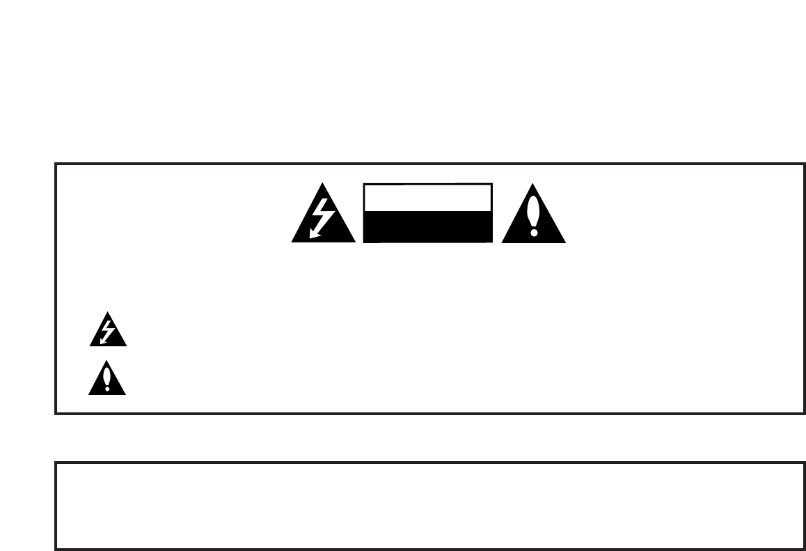
RECORD Model and SERIAL NUMBER
The model and serial number of this TV is located on the
back of the cabinet. For future reference, we suggest that
you record those numbers here:
Model No._________________Serial No. _______________
WARNING: TO REDUCE THE RISK OF ELECTRIC SHOCK DO NOT REMOVE COVER (OR BACK). NO USER
SERVICEABLE PARTS INSIDE. REFER TO QUALIFIED SERVICE PERSONNEL
The lightning flash with arrowhead symbol, within an equilateral triangle, is intended to alert the user to the
presence of uninsulated “dangerous voltage” within the product’s enclosure that may be of sufficient magnitude
to constitute a risk of electric shock to persons.
The exclamation point within an equilateral triangle is intended to alert the user to the presence of important
operating and maintenance (servicing) instructions in the literature accompanying the appliance
WARNING:
TO PREVENT FIRE OR SHOCK HAZARDS, DO NOT EXPOSE THIS PRODUCT TO RAIN OR MOISTURE.
POWER CORD POLARIZATION:
This product is equipped with a 3-wire grounding-type alternating current line plug. This plug will fit into the power outlet
only one way. This is a safety feature. If you are unable to insert the plug fully into the outlet, contact your electrician to
replace your obsolete outlet. Do not defeat the safety purpose of the three-wire ground type plug.
NOTE TO CABLE/TV INSTALLER:
This reminder is provided to call the cable TV system installer’s attention to Article 820-40 of the National Electric Code
(U.S.A.). The code provides guidelines for proper grounding and, in particular, specifies that the cable ground shall be con-
nected to the grounding system of the building, as close to the point of the cable entry as practical.
REGULATORY INFORMATION:
This equipment has been tested and found to comply with the limits for a Class B digital device, pursuant to Part 15 of the
FCC Rules. These limits are designed to provide reasonable protection against harmful interference when the equipment is
operated in a residential installation. This equipment generates, uses and can radiate radio frequency energy and, if not
installed and used in accordance with the instruction manual, may cause harmful interference to radio communications.
However, there is no guarantee that interference will not occur in a particular installation. If this equipment does cause
harmful interference to radio or television reception, which can be determined by turning the equipment off and on, the user
is encouraged to try to correct the interference by one or more of the following measures:
• Reorient or relocate the receiving antenna.
• Increase the separation between the equipment and receiver.
• Connect the equipment into an outlet on a circuit different from that to which the receiver is connected.
• Consult the dealer or an experienced radio/TV technician for help.
CAUTION:
Do not attempt to modify this product in any way without written authorization from LG Electronics U.S.A., Inc.
Unauthorized modification could void the user’s authority to operate this product.
COMPLIANCE:
The responsible party for this product’s compliance is: LG Electronics U.S.A., Inc.
1000 Sylvan Avenue, Englewood Cliffs, NJ 07632, USA • Phone: 1-201-816-2000.
WARNING
RISK OF ELECTRIC SHOCK
DO NOT OPEN
For Customer Support/Service, please call:
1-888-865-3026
www.lgcommercial.com • www.zenith.com
Marketed and Distributed in the United States by LG Electronics U.S.A., Inc.
2000 Millbrook Drive, Lincolnshire, IL 60069
©Copyright 2009, LG Electronics U.S.A., Inc. 206-4118
PAGE 2

SAFETY INSTRUCTIONS
Important safeguards for you and your new product
This product has been manufactured and tested with safety in mind. However, improper use can result in potential electrical shock
or fire hazards. To avoid defeating the safeguards that have been built into the new product, please read and observe the following
safety points when installing and using the new product, and save them for future reference.
Observing the simple precautions discussed in this installation and operating guide can help get many years of enjoyment and safe
operation that are built into the new product.
This product complies with all applicable U.S. Federal safety requirements, and those of the Canadian Standards Association
IMPORTANT SAFETY INSTRUCTIONS
PAGE 3
206-4118
1. Read Instructions
All the safety and operating instructions should be read before
the product is operated.
2. Follow Instructions
All operating and use instructions should be followed.
3. Retain Instructions
The safety and operating instructions should be retained for
future reference.
4. Heed Warnings
All warnings on the product and in the operating instructions
should be adhered to.
5. Cleaning
Unplug this product from the wall outlet before cleaning. Do
not use liquid cleaners or aerosol cleaners. Use a damp cloth
for cleaning.
6. Water and Moisture
Do not use this product near water for example, near a bath
tub, wash bowl, kitchen sink, or laundry tub, in a wet base-
ment, or near a swimming pool.
7. Accessories, Carts, and Stands
Do not place this product on a slippery or tilted surface, or on
an unstable cart, stand, tripod, bracket, or table. The product
may slide or fall, causing serious injury to a child or adult, and
serious damage to the product. Use only with a cart, stand, tri-
pod, bracket, or table recommended by the manufacturer, or
sold with the product. Any mounting of the product should fol-
low the manufacturer’s instructions, and should use a mounting
accessory recommended by the manufacturer.
8. Transporting Product
A product and cart combination should be moved with care.
Quick stops, excessive force, and uneven surfaces may cause
the product and cart combination to overturn.
9. Attachments
Do not use attachments not recommended by the product man-
ufacturer as they may cause hazards.
10. Ventilation
Slots and openings in the cabinet are provided for ventilation
and to ensure reliable operation of the product and to protect
it from overheating, and these openings must not be blocked or
covered. The openings should never be blocked by placing the
product on a bed, sofa, rug, or other similar surface. This prod-
uct should not be placed in a built-in installation such as a
bookcase or rack unless proper ventilation is provided or the
manufacturer’s instructions have been adhered to.
11. Power Sources
This product should be operated only from the type of power
source indicated on the marking label. If you are not sure of
the type of power supply to your home, consult your product
dealer or local power company. For products intended to oper-
ate from battery power, or other sources, refer to the operating
instructions.
12. Power Cord Polarization (Some models)
This product is equipped with a three-wire grounding type
alternating-current power plug. This plug will fit into the power
outlet only one way. This is a safety feature. If you are unable
to insert the plug fully into the outlet, contact your electrician
to replace your obsolete outlet. Do not defeat the safety pur-
pose of the three-wire ground-type plug.
13. Power Cord Protection
Power-supply cords should be routed so that they are not likely
to be walked on or pinched by items placed upon or against
them, paying particular attention to cords at plugs, conve-
nience receptacles, and the point where they exit from the
product.
PORTABLE CART WARNING
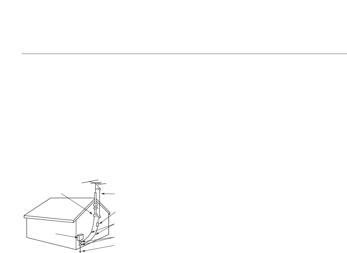
206-4118
PAGE 4
IMPORTANT SAFETY INSTRUCTIONS
(Continued from previous page)
14. Outdoor Antenna Grounding
If an outside antenna or cable system is connected to the prod-
uct, be sure the antenna or cable system is grounded so as to
provide some protection against voltage surges and built-up
static charges. Article 810 of the National Electrical Code
(U.S.A.), ANSI/ NFPA 70 provides information with regard to
proper grounding of the mast and supporting structure, ground-
ing of the lead-in wire to an antenna discharge unit, size of
grounding conductors, location of antenna-discharge unit, con-
nection to grounding electrodes, and requirements for the
grounding electrode.
15. Lightning
For added protection for this product (receiver) during a light-
ning storm, or when it is left unattended and unused for long
periods of time, unplug it from the wall outlet and disconnect
the antenna or cable system. This will prevent damage to the
product due to lightning and power-line surges.
16. Power Lines
An outside antenna system should not be located in the vicini-
ty of overhead power lines or other electric light or power cir-
cuits, or where it can fall into such power lines or circuits.
When installing an outside antenna system, extreme care should
be taken to keep from touching such power lines or circuits as
contact with them might be fatal.
17. Overloading
Do not overload wall outlets and extension cords as this can
result in a risk of fire or electric shock.
18. Object and Liquid Entry
Never push objects of any kind into this product through
openings as they may touch dangerous voltage points or
short-out parts that could result in a fire or electric shock.
Never spill liquid of any kind on the product.
19. Servicing
Do not attempt to service this product yourself as opening or
removing covers may expose you to dangerous voltage or other
hazards. Refer all servicing to qualified service personnel.
20. Damage Requiring Service
Unplug this product from the wall outlet and refer servicing to
qualified service personnel under the following
conditions:
a. If the power-supply cord or plug is damaged.
b. If liquid has been spilled, or objects have fallen into the
product.
c. If the product has been exposed to rain or water.
d. If the product does not operate normally by following the
operating instructions. Adjust only those controls that are
covered by the operating instructions as an improper adjust-
ment of other controls may result in damage and will often
require extensive work by a qualified technician to restore
the product to its normal operation.
e. If the product has been dropped or the cabinet has been
damaged.
f. If the product exhibits a distinct change in performance.
21. Replacement Parts
When replacement parts are required, be sure the service tech-
nician has used replacement parts specified by the manufactur-
er or have the same characteristics as the original part.
Unauthorized substitutions may result in fire, electric shock, or
other hazards.
22. Safety Check
Upon completion of any service or repairs to this product, ask
the service technician to perform safety checks to determine
that the product is in proper operating condition.
23. Wall or Ceiling Mounting
The product should be mounted to a wall or ceiling only as rec-
ommended by the manufacturer. The product may slide or fall,
causing serious injury to a child or adult, and serious damage
to the product.
24. Heat
The product should be situated away from heat sources such as
radiators, heat registers, stoves, or other products (including
amplifiers) that produce heat.
Antenna Lead in Wire
Antenna Discharge Unit
(NEC Section 810-20)
Grounding Conductor
(NEC Section 810-21)
Ground Clamps
Power Service Grounding
Electrode System (NEC
Art 250, Part H)
Ground Clamp
Electric Service
Equipment
Example of Grounding According to National Electrical Code
Instructions
NEC - National Electrical Code

PAGE 5
206-4118
Use this page as a reference to find pages or sections to go to and set up the TV features.
Go to page 7 to begin the Commercial Mode Master TV setup.
Warnings . . . . . . . . . . . . . . . . . . . . . . . . . . . . . . . . . . 2
Important Safety Instructions . . . . . . . . . . . . . . . . . . 3 - 4
Table of Contents . . . . . . . . . . . . . . . . . . . . . . . . . . . . 5
Setup Checklist . . . . . . . . . . . . . . . . . . . . . . . . . . . . . . 6
Commercial Mode Setup for Master TV . . . . . . . . . . . . . 7
Installer Overview . . . . . . . . . . . . . . . . . . . . . . . . . . . . 8
FTG Card Mode of Operation Overview . . . . . . . . . . . . . . . 9
FTG Card Operation Setup . . . . . . . . . . . . . . . . . . . . . . 10
FTG Card Channel Map Overview . . . . . . . . . . . . . . . . . . 11
FTG Installer Menu Overview . . . . . . . . . . . . . . . . . . . . . 12
FTG Operation Troubleshooting . . . . . . . . . . . . . . . . . . . 13
Typical Installer’s Remote Control . . . . . . . . . . . . . . . . . 14
Installer Remote Control Key Functions . . . . . . . . . . . . . . 15
Rear Connections Panel . . . . . . . . . . . . . . . . . . . . . . . . 16
A/V Input 2 Side Connections Panel/RF Antenna Connection 17
RJP / TV Connections & Setup . . . . . . . . . . . . . . . . . . . 18
MPI Card Slot / PPV Card Installation . . . . . . . . . . . . . . . 19
TV Features Configuration Menus Overview . . . . . . . . . . . 20
TLL-1100A Cloning Instructions / Learning Setup . 21 -22 - 23
LT2002 Cloning Instructions . . . . . . . . . . . . . . . . . 24 - 25
Installer Menus . . . . . . . . . . . . 26 - 27 - 28 - 29 - 30 - 31
References
Detailed Instructions For Making A Master TV . . . . . . . . . 32
Editing Channel Icons/Adding Ch Labels 2-5-4 + Menu Mode 33
Clonable Menu Features / Checking Software Version . . . . . 34
USB End User Features . . . . . . . . . . . . . . . . . . . . . . . . 35
USB Cloning Setup: Master TV Learning . . . . . . . . . . . . . 36
USB Cloning Setup: Master TV Teaching . . . . . . . . . . . . . 37
TV Camport Auto Sense Operation . . . . . . . . . . . . . . . . . 38
TV Aux Input Configuration / Troubleshooting . . . . . . . . . 39
Troubleshooting . . . . . . . . . . . . . . . . . . . . . . . . . . . . . 40
LT2002 Cloning Troubleshooting . . . . . . . . . . . . . . . . . . 41
Troubleshooting Flow Chart . . . . . . . . . . . . . . . . . . . . . 42
Commercial Mode Check . . . . . . . . . . . . . . . . . . . . . . . . 43
Glossary of Terms . . . . . . . . . . . . . . . . . . . . . . . . . . . . 44
B-LAN Setup and Overview . . . . . . . . . . . . . . . . . . . . . . 45
RJP Model List and Input Hierarchy . . . . . . . . . . . . . . . . 46
Notes . . . . . . . . . . . . . . . . . . . . . . . . . . . . . . . . . . . 47
Back Cover . . . . . . . . . . . . . . . . . . . . . . . . . . . . . . . . 48
Notes
• See the Installer’s menus to set up the operational features of the TV. The Installer’s section content is intended to be used pri-
marily by qualified TV electronics technicians.
• Reference is made to installer remote controls used for menu operation within the manual. The remote information is provided
for reference only. The typical installer remote control shown for reference in this manual may be different than the actual
remote control supplied with the TV.
• For any additional information, contact your LG representative.
Note: Design and specifications are subject to change without prior notice.
Marketed and Distributed in the United States by LG Electronics U.S.A., Inc.
1000 Sylvan Avenue
Englewood Cliffs, NJ 07632
Table of Contents
For Customer Support/Service please call:
1-888-865-3026
www.lgcommercial.com
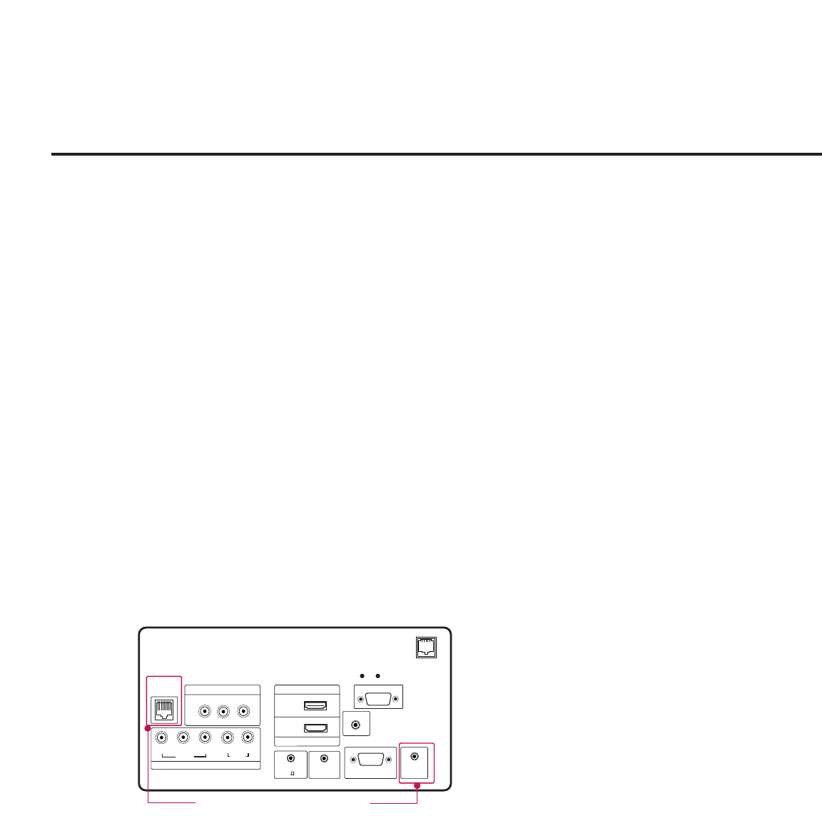
206-4118
PAGE 6
Setup Checklist
Installation and Setup Checklist
__ Unpack TV and all accessories.
__ Install batteries in remote control.
__ Install TV on Vesa Mount or Stand.
Note: It may be advisable to make all hard-
wire connections before installing on Vesa
mount or stand, as appropriate.
Hardware Connections
__ Install any additional hardware as
appropriate to your institution, LAN etc.
Hardwire Connections
__ Make all connections to rear Jack Pack and
RF antenna on MPI card.
__ Make all connections to signal, interactive
resources and Aux sources as appropriate.
Installer Menu Items Setup
__ Configure all relevant Installer menu items
as required of your institution.
TV Menus Configuration
Configure TV features for the end user.
__ Channel
__ Picture
__ Audio
__ Option
__ Time
__ Lock
__ Choose on screen menu language.
(English is the default language.)
Commercial Mode Setup
__ Commercial Mode Setup, see next page.
Software Installation
__ Install or configure any software as applic-
able; PPV etc.
Additional Features Setup
See page 5, Table of Contents.
__ Select viewing source on TV.
HDMI
GAME
CONTROL
COMPONENT IN
VIDEO AUDIO
R
L
RGB IN (PC)
RS-232C IN
(SERVICE ONLY)
UPDATE
RESET
AUDIO IN
REMOTE
CONTROL OUT
SPEAKER OUT
(8 )
PB
YPR
.....
.....
.....
.....
....
..........
..........
2
1
RJP
AV IN 1
VIDEO AUDIO
R
L(MONO)
HDMI/DVI IN
TV-LINK
CFG
(RGB / DVI)
Except 32LH240H
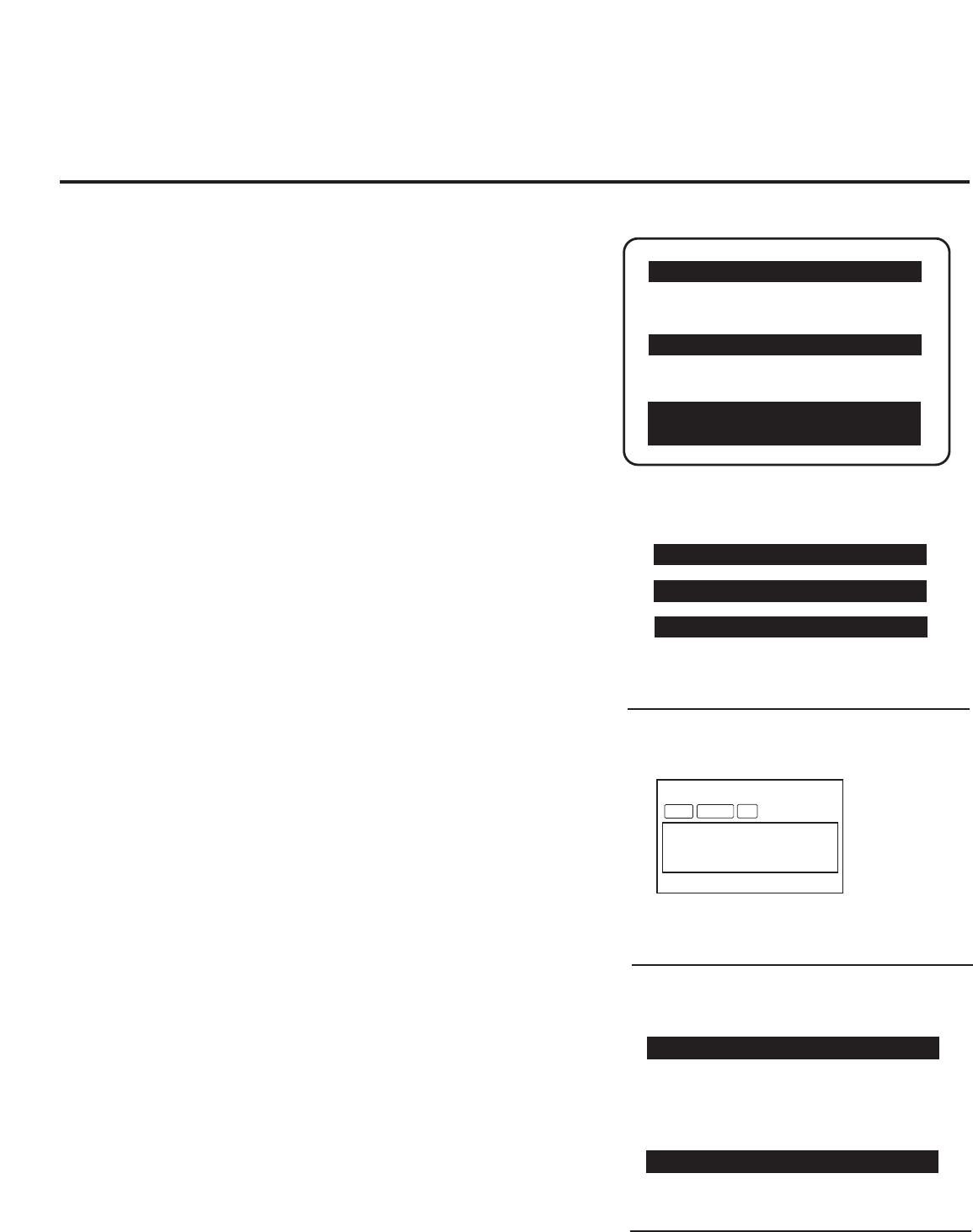
PAGE 7
206-4118
Commercial Mode Setup for Master TV
This page provides an overview of a Master TV configuration.
Note 1: Disconnect all Aux inputs. Under certain conditions, Auto Tuning (Channel
search) is disabled if there is an Aux input active.
Commercial Mode Setup Procedure
1. Set Installer Menu Items
(Enter TV Installer Menu, see Installer menus for detailed instructions.)
a. Set Installer menu item 117 FACT DEFAULT, to 001 and press ENTER on
Installer remote. (This clears all installer menu custom settings, channel
labels / icons etc. and reloads the factory default settings.)
b. Set Item 003 BAND/AFC.
- Broadcast: set to 000.- HRC: set to 002
- CATV: set to 001. -IRC: set to 003
c. Set item 028 CH OVERIDE to 001. This allows access to channel search,
Auto Tuning and Channel List/Edit options in the Channel Menu.
d. Set other particular installer items that affect your TV programming net-
work. Enable/Disable Aux sources, set a Start Channel etc.
e. After all required installer menu item settings have been adjusted, press
ENTER on the remote to remove Installer Menu.
2. Set Up TV Features
(Channel, Picture, Audio, Lock, Time, Option, Digital Captions etc. See TV
Clonable options list and TV menus pages.)
3. Run Auto Tuning (Channel Search)
(Search for all available channels.) Go to the Channel Menu and access
the Auto Tuning option, follow onscreen instructions.
a. Edit Channel Scan. In the Channel Menu, access Channel Edit option.
• Add/Delete channels per your system requirements.
Note: Physical channel numbers are used to identify Virtual channels.
• Add familiar channel trademarks/logos like ABC, CBS, NBC etc. to the
Channel-Time onscreen display. In the Channel menu, select the Channel
Label option. Add identifiable labels (logos) for the end user to readily
know what common networks are available.
4. Transfer TV Setup to Internal TV Controller: 2-5-5 + Menu Mode
After the TV channel scan has been edited and channel label icons
added, enter the Installer menu. Once in the Installer menu, press 2-5-5
and MENU on the remote. This transfers the TV setup to the internal
controller box.
5. Add Custom Channel Labels for Analog Channels: 2-5-4 + Menu Mode
Enter Installer menu, press 2-5-4 and MENU. Add your own custom text
labels to channel onscreen displays. Note: Digital Channels often have a
broadcaster generated label. (See 2-5-4+Menu pages.)
When finished, to exit 2-5-4+Menu mode, press MENU.
Verify TV Setup
At this point, verify that the channel lineup, channel icons and custom
labels are correct. Make sure the TV features are set per your requirements.
Set item 028 Ch Overide to 000 to lock the channel scan. After the pre-
ceding has been completed, the Master TV setup is ready to be copied to a
Clone Programmer, see cloning options pages.
003 BAND/AFC 00X
028 CH. OVERIDE 001
117 FACT DEFAULT 00X
Typical TV Installer Menu
Adjust the settings for these
Installer Menu Items
DIGITAL 19-3
WXYZ
MONO STEREO SAP
Custom Text Label ‘WXYZ’ created in
2-5-4 + Menu (Add Channel Label) Mode
028 CH. OVERIDE 000
After Master TV setup has been completed,
set item 028 Ch Overide to 000.
000 INSTALLER SEQ 000
UPN 000-000-000-000 FPGA E0F1
PTC V1.00.000 CPU V3.06.00
XXLH250H INSTALLER MENU
093 RJP AVAILABLE 001
Set 093 RJP Available to 001 if using a remote
jack pack
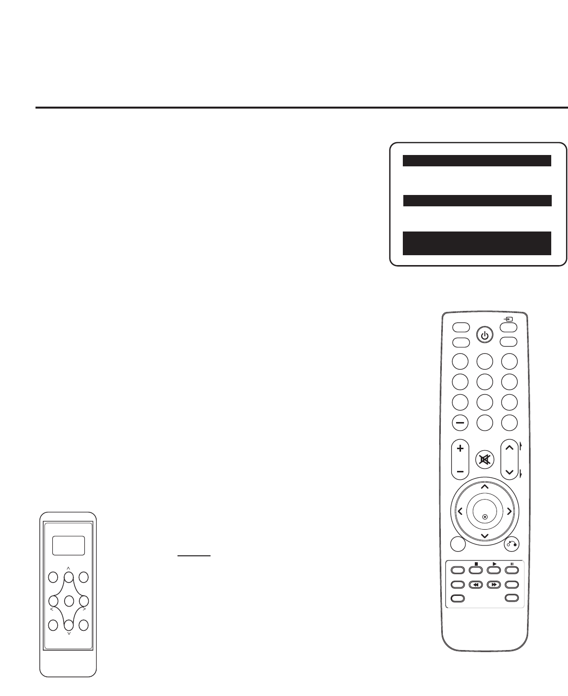
Installer Overview
This is the commercial mode setup guide only.
Operating Installer Menu
To set up the controls for the TV you will need to know how to enter
the TV Installer menu and make changes to the default values as
required. If necessary, familiarize yourself with the TV Installer menu
and how to make and save changes in the menu.
LG Installer Remote
You will need an LG Installer remote control similar to the one
shown to the right. The installer remote must have a “Source” but-
ton or its equivalent. The remote shown in this manual has “INPUT”
-- this button serves the purpose of a Source button.
The TV’s clonable features need to be set up. This is a critical step.
If the Master TV display panel’s clonable features like adding channel
icons or channel labels are not done correctly, then the cloned TVs
will all have problems. Refer to the Owner’s Manual for other TV fea-
tures: Video, Audio, Closed Captions, V-Chip, etc.
TLL-1100A Clone Programmer
The TLL is a very simple cloner to use. It can be set up to clone a
master TV setup and transfer it into a target TV. Cloning is accom-
plished using the TV/Cloner MPI ports for communica-
tion. Be sure the Master TV is set up completely.
Cloning is only possible when the TV is tuned to an
Aux source or Analog channel, not a digital channel.
Typical Installer Menu
TV Link
Loader-Demo
TLL1100A
Ready
TLL1100A
ENTER
RECEIVE SEND
MENU
MODE
MENU
LIST
123
456
78
0
9
FLASHBK
MUTE
VOL
CH
P
A
G
E
RETURN
MARK
ENTER
INPUT
POWER
RATIO
CC
TIMER
ALAM
SAP
EJECT
206-4118
PAGE 8
000 INSTALLER SEQ 000
UPN 000-000-000-000 FPGA E0F1
PTC V1.00.000 CPU V3.06.00
XXLH250H INSTALLER MENU
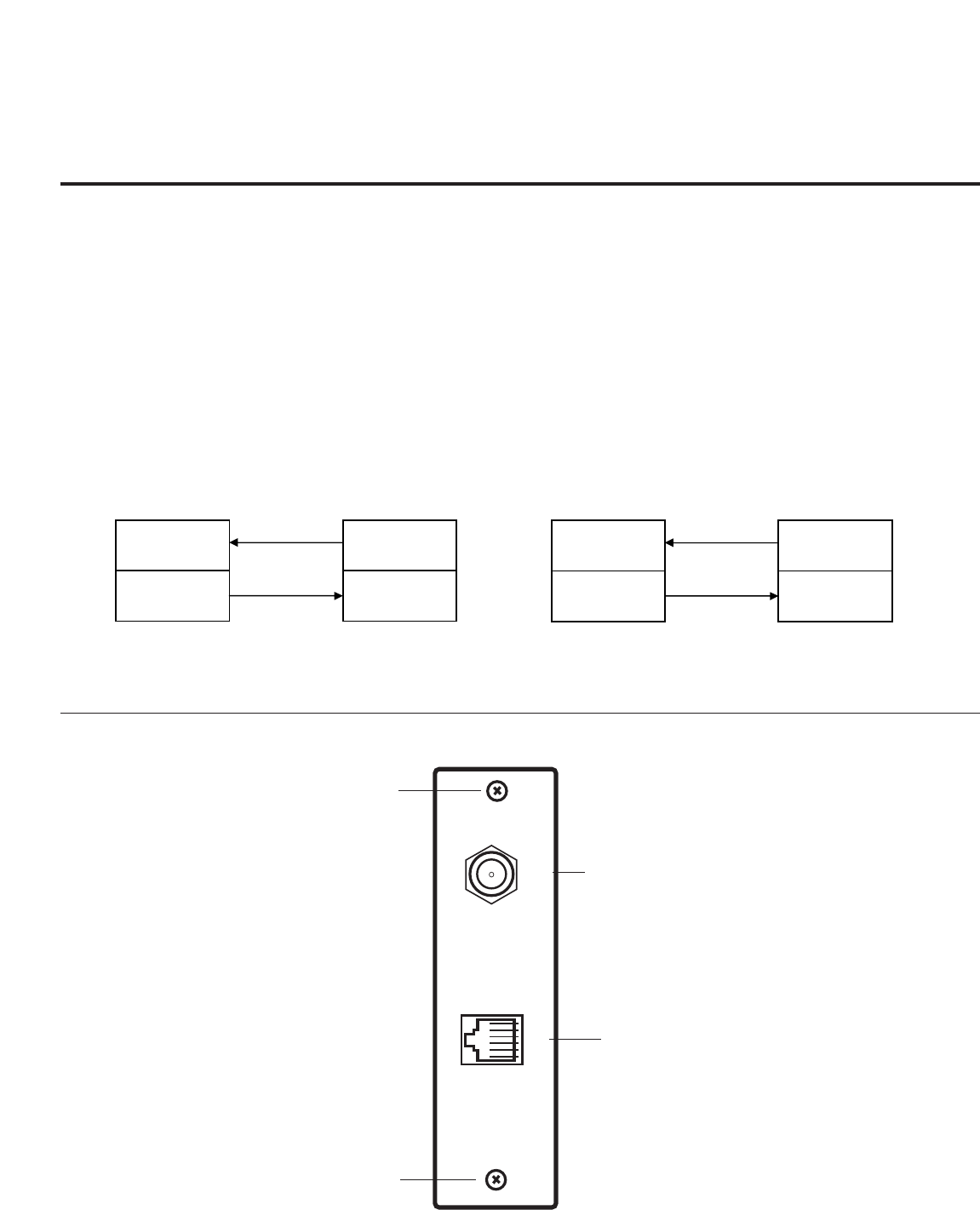
PAGE 9
206-4118
FTG Card Mode of Operation Overview
Outlined below is the FTG (Free-To-Guest) setup for individual TV control
ANTENNA IN M.P. I.
ANTENNA/CABLE INPUT
Receives RF signals.
RETAINING SCREW
Install after inserting
the LMT7Z7 card.
RETAINING SCREW
Install after inserting
the LMT7Z7 card.
M.P.I. INTERFACE
Available MPI port.
FTG CARD TARGET TV/STB
CHANNEL
MAP
INSTALLER
MENU
CHANNEL
INSTALLER
MENU
MAP
FTG CARD TARGET TV/STB
CHANNEL
MAP
INSTALLER
MENU
CHANNEL
INSTALLER
MENU
MAP
1. Set up commercial features of TV/STB. Enter Installer Menu and set all desired items as required. (i.e. Tuning
Band, Start Channel etc.) Refer to the Installation and Setup Guide of the TV/STB.
2. Load the FTG Configuration Application program onto the PC that will be used to configure the FTG card.
3. Install FTG card into TV/STB’s MPI card slot and connect PC. (See below)
4. Execute the FTG Configuration Application and create a configuration file.
5. Build a Channel Map and ‘Write’ it to FTG card. (Converts card from pass-through to FTG mode.)
6. If necessary, make changes to Installer Menu items using FTG Installer Menu Configuration utility and ‘Write’
them to FTG card.
7. Save the configuration file (*.rml) for future use.
8. Tune TV/STB to a Logical Channel in the Channel Map.
LMT7Z7 Configured Card in FTG Mode of Operation
Different Model TV/STB Function
Card only copies Installer Menu items
and then installs Channel Map.
Same Model TV/STB Function
Card installs both Installer Menu items
and Channel Map.
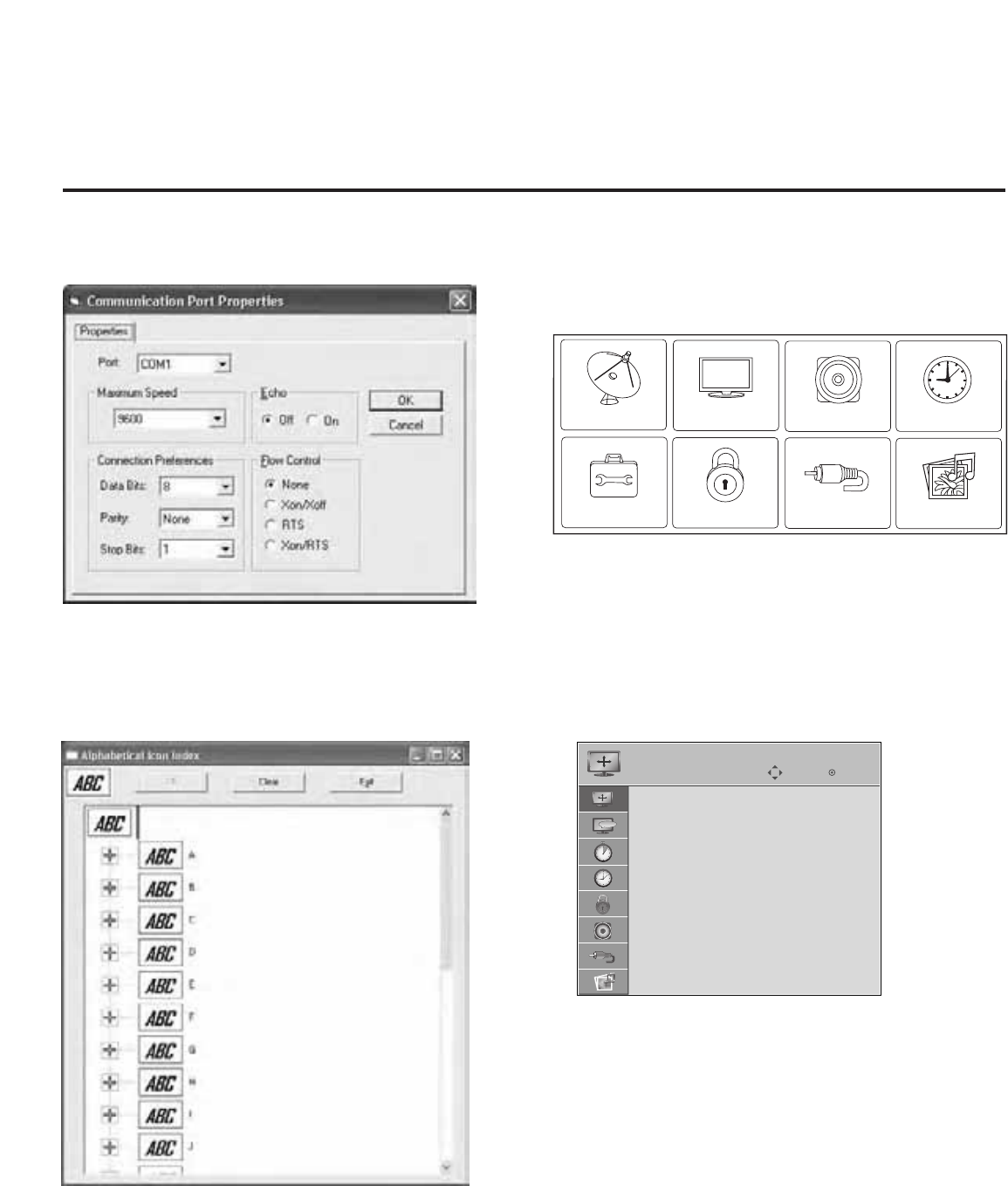
206-4118
PAGE 10
CHANNEL PICTURE AUDIO TIME
INPUT USB
OPTION LOCK
Typical TV/STB Setup Menu
Shows that the Z7 card is in pass-through mode. This menu can
also be accessed by turning IR remote access ‘On’ in the FTG
Configuration Application, while the TV/STB is in FTG mode.
End User ‘Aspect Ratio’ or Function Menu
Shows that the Z7 card is in FTG mode. While this menu is present
on-screen, the only way the Installer menu can be accessed is by
the FTG Configuration Application.
Communications Setup Menu
Sets up the communications link between the FTG Configuration
Application and the Z7 card installed in a TV/STB.
Network Icon Selection Menu
Select channel icons like ABC, NBC etc., to add to the channel
OSDs to identify common networks for the end user.
FTG Card Mode of Operation Contd.
It is easy to determine the operating mode of the TV/STB. By pressing Menu, if the Setup or TV menu appears, the Z7 card is in
pass-through mode. If the End User ‘Function’ menu appears, the TV/STB is in FTG mode.
ABC
Move
Enter
ASPECT RATIO
Set By Program
4:3
16:9
Zoom
Just Scan
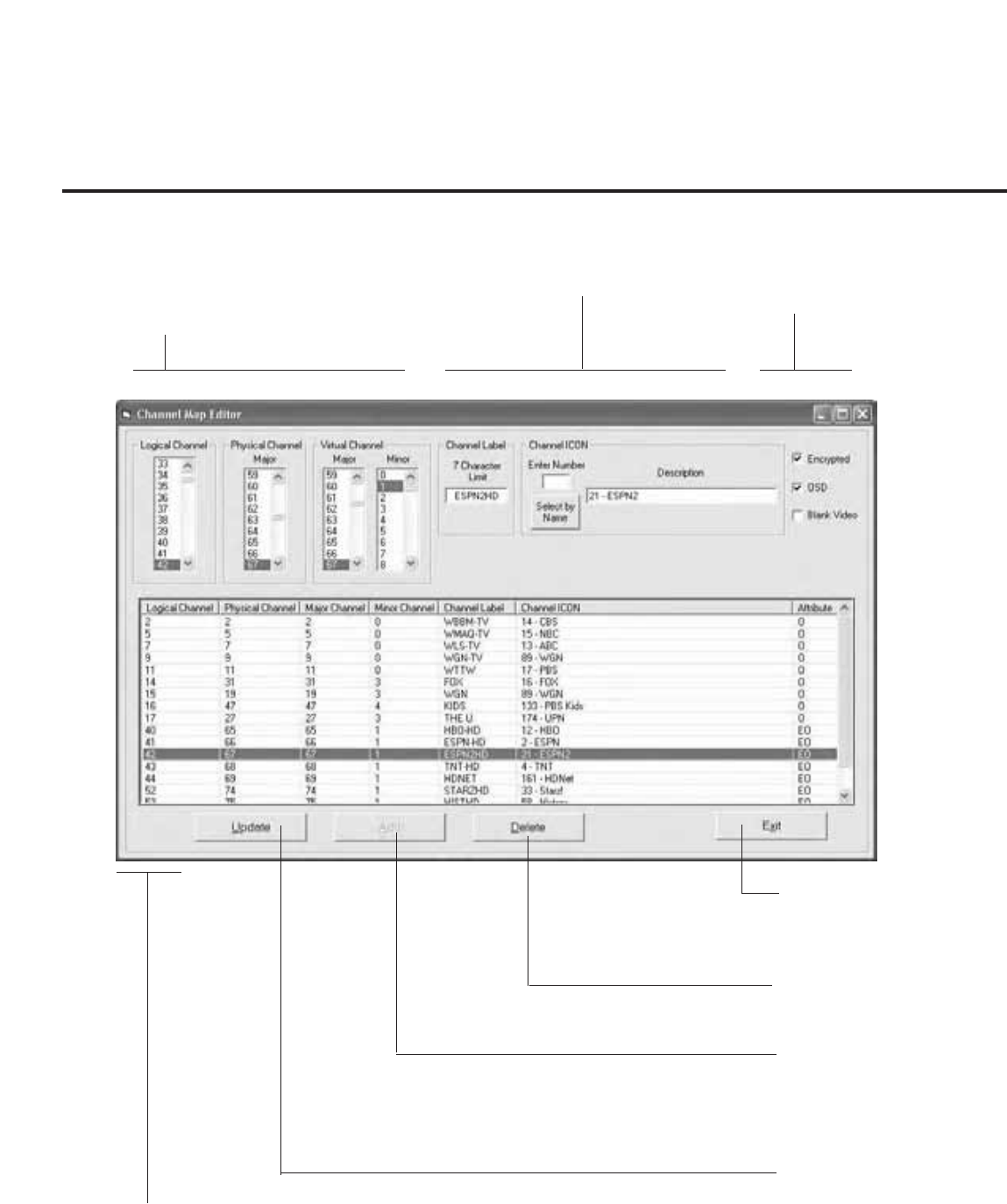
PAGE 11
206-4118
DELETE
Removes channel from lineup.
ADD
After inputting a new chan-
nel’s data, press to add chan-
nel to list.
CHANNEL MAP EDITOR
Shows both channel data
and logical channel lineup.
EXIT
Exits menu and returns to logical
channel listing.
LOGICAL CHANNEL NUMBERS
Channels appear in numerical order.
Select logical, Major and Minor num-
bers on menu.
CUSTOM CHANNEL LABELS/ICONS
Set custom labels and select icons on menu. SET CHANNEL ATTRIBUTES
Set encrypted, OSD on or off or blank
video only.
UPDATE
After editing a channel’s data,
press to include the changes
in the channel list.
FTG Channel Map Overview
Creating/copying a channel map into LMT7Z7 card will convert the card from pass-through mode to FTG mode. When ‘Aspect Ratio’
menu is present, card is in FTG mode.
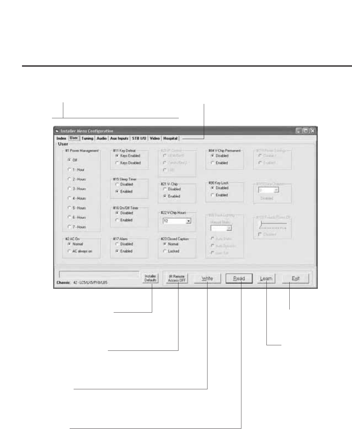
LEARN
Press to transfer the installer
menu settings on the TV/STB
to the FTG card and PC FTG
Configuration Application.
INSTALLER DEFAULTS
Press to reset TV/STB to Installer
menu defaults.
READ
Press to transfer the Installer menu values on the FTG card to
the PC FTG Configuration Application.
WRITE
Press to transfer the FTG Installer menu
values to the FTG card and TV/STB.
EXIT
Returns to logical channel
map menu.
IR REMOTE ACCESS
Toggle IR remote access to On to get access to
TV/STB feature menus or Installer menu.
CONFIGURATION SETTINGS
Select tabs for Installer submneu
items to set up TV/STB.
HOSPITAL GRADE TV/STB ITEMS
Set hospital only items on Installer menu for
Hospital grade TV/STBs.
206-4118
PAGE 12
FTG Installer Menu Overview

LMT7Z7 Configured Card in FTG Mode of Operation
Error Messages
Problem Probable Cause Solution
Cannot contact FTG application Close extra FTG application on computer.
target. already open.
Cable(s) not Check and connect communication cables.
connected.
TV off. Turn TV on.
Wrong Communication port. Select correct Comm port on computer.
PAGE 13
206-4118
FTG Operation Troubleshooting
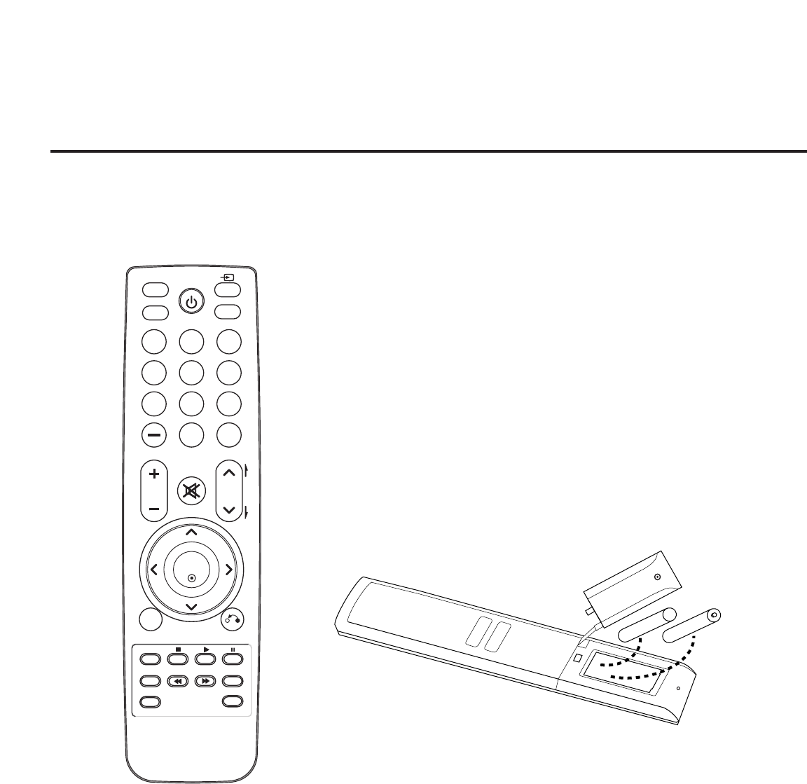
206-4118
Typical Installer Remote Control
LG Installer Remote Control
The remote control is supplied with and dedicated to operate the TV.
Some DVD and VCR controls may be available for some LG DVD/VCR
products.
See next page for typical key functions in TV mode and
DVD/VCR control.
Follow the instructions provided in the Installer menu pages to access
the Installer menus.
Installing Batteries in Installer Remote Control
• Remove the battery compartment cover on the back side by
loose the bolt on the battery compartment cover, pressing the
arrow tab and sliding the cover downward. Install batteries
matching correct polarity as shown (+ with + and - with -).
• Install two high-quality alkaline 1.5V AAA batteries. Never mix
old or used batteries with new ones. Replace cover.
+ AAA
AAA +
MENU
LIST
123
456
78
0
9
FLASHBK
MUTE
VOL
CH
P
A
G
E
RETURN
MARK
ENTER
INPUT
POWER
RATIO
CC
TIMER
ALAM
SAP
EJECT
PAGE 14
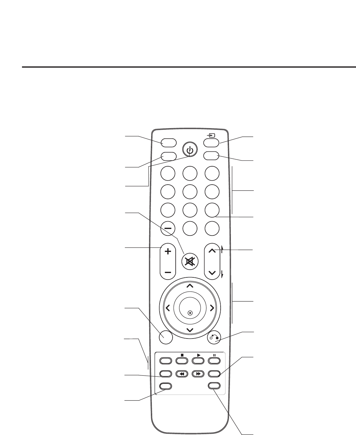
MARK
Use to mark or unmark a photo/music.
RATIO
Adjusts the picture aspect ratio.
POWER
Turns TV On or Off.
MUTE
Switches the sound On or Off.
VOLUME UP/DOWN
Increases/decreases the sound level.
MENU
Displays the main menu on the screen.
Enters or exits the on-screen menu system
VCR/DVD BUTTONS
Control some video cassette recorders or DVD
players. (“RECORD” is not functional in DVD
mode.) Set up for VCR recording: Once, Regularly,
Weekly, Off. (“RECORD” button only).
TIMER
Sets the amount of time before the TV
automatically turns itself Off.
ALARM
Sets the time that the TV
will automatically turn itself On.
INPUT
Selects RGB, HDMI,DVI, HDMI2, Component
Input, AV1 and AV2 sources.
CC
Selects a closed caption option:
Off, CC1 ~ 4, Text1 ~ 4, Service 1 ~6.
NUMBER Buttons (0 - 9) DASH
Use to enter a program number or channels.
Dash is used for sub channel numbers such as
2-1, 2-2, 9-1, 9-2, 100-3, 100-4 etc.
FLASHBACK
Returns to the previously tuned channel.
CHANNEL UP/DOWN
Selects available channels found with Auto
Tuning. Moves to next available page in elec-
tronic program guide.
THUMBSTICK
Up/Down/Left/Right/ENTER
Use to navigate on-screen menus / adjust the TV
settings to your requirements.
RETURN
Clears all on-screen displays and returns
to TV viewing from any TV menu.
SAP
Selects MTS sound:
Mono, Stereo, and SAP in Analog mode.
Changes the audio language in DTV mode, if
additional languages are available.
SAP Notes
• If SAP is selected and no SAP is provided,
sound may not be heard on channel.
• Each analog channel may have its own SAP
setting.
• Digital channels will reset to default audio lan-
guage with a power Off/On.
EJECT
Clears all on-screen displays and returns
MENU
LIST
123
456
78
0
9
FLASHBK
MUTE
VOL
CH
P
A
G
E
RETURN
MARK
ENTER
INPUT
POWER
RATIO
CC
TIMER
ALAM
SAP
EJECT
Remote Control Key Functions: This typical LG TV remote control is shown for reference. Follow the instructions
provided on the Installer menu pages to access the Installer menu.
Installer Remote Control Typical Key Functions
PAGE 15
206-4118
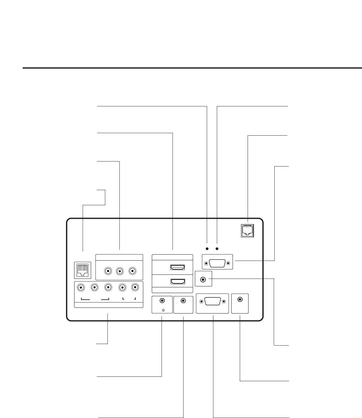
HDMI
GAME
CONTROL
COMPONENT IN
VIDEO AUDIO
R
L
RGB IN (PC)
RS-232C IN
(SERVICE ONLY)
UPDATE
RESET
AUDIO IN
REMOTE
CONTROL OUT
SPEAKER OUT
(8 )
PB
YPR
.....
.....
.....
.....
....
..........
..........
2
1
RJP
AV IN 1
VIDEO AUDIO
R
L(MONO)
HDMI/DVI IN
TV-LINK
CFG
(RGB / DVI)
Rear Connections Panel
206-4118
PAGE 16
AUDIO IN (RGB / DVI)
Audio connection for either
RGB or DVI device.
COMPONENT IN
Connect to output jacks on
component device.
HDMI/DVI PORT
Connect to output jacks from
HDMI / DVI device.
TV-LINK
Use for FTG downloads.
(Except 32LH240H)
SPEAKER OUT
8-OHM
Connect to external speaker
input.
REMOTE CONTROL OUT
Connect to remote control
device.
RGB IN (PC)
Connection for RGB hookup
from PC.
RS-232C IN
Used for downloading soft-
ware updates, etc.
UPDATE
Restricted to software
updates.
RESET
Press RESET to
re-initialize the TV.
REMOTE JACK PACK PORT
Connect to remote jack pack
control output port.
LAN
Connect to control network.
(Except 32LH240H)
AUDIO/VIDEO IN 1
Connect to output jacks on
audio/video device.
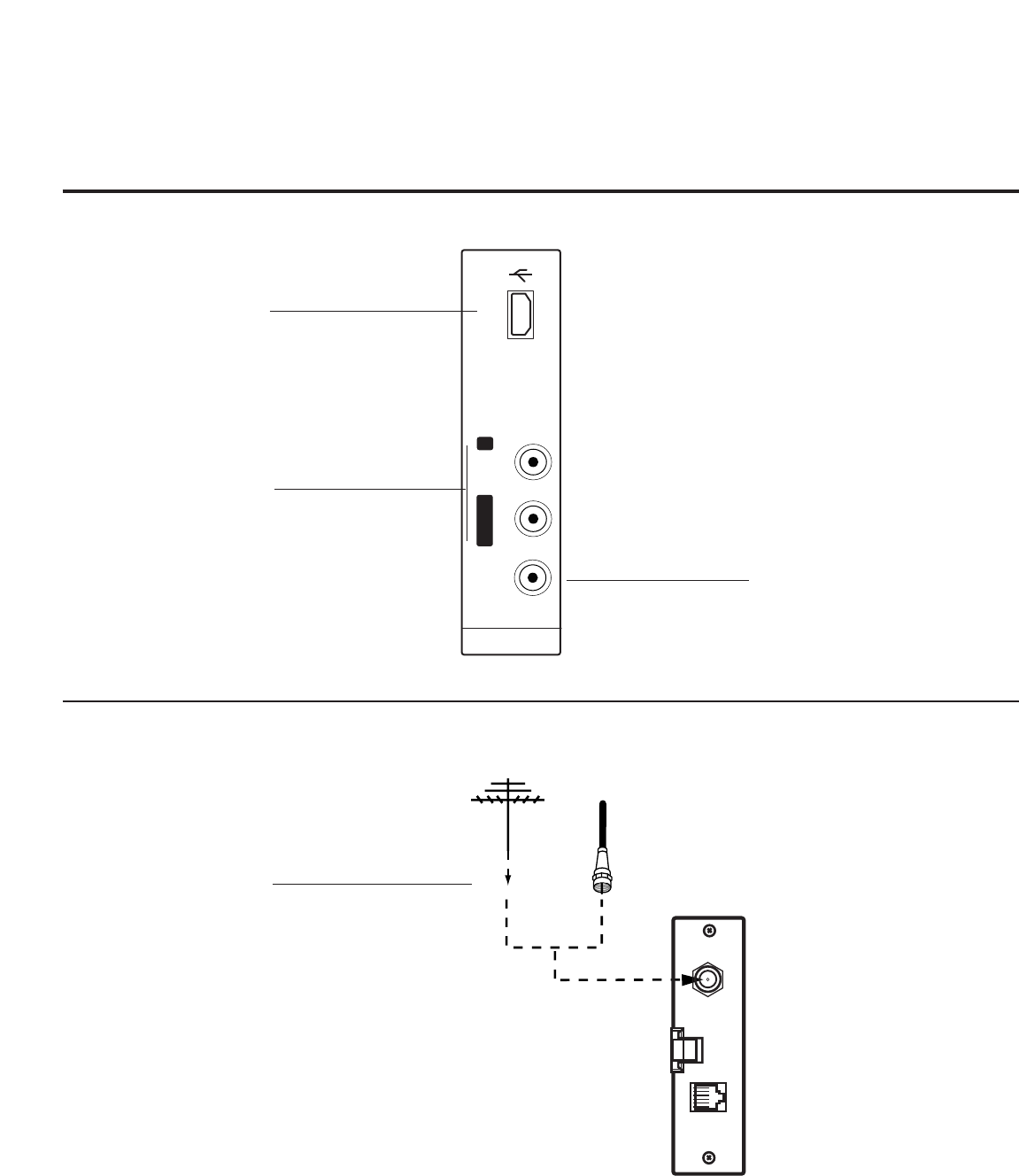
PAGE 17
206-4118
A/V 2 Input: Side Connections Panel / RF Antenna Connection
AV IN 2
L/MONO -AUDIO- R
VIDEO USB IN
......
.....
VIDEO IN
Connect to video output port
on external device.
L/MONO-AUDIO-R IN
Connect to audio output jacks
from external device.
For mono audio output,
connect to Left audio input.
USB IN
Insert USB device for software
updates and usable for
Picture/Music entertainment.
Antenna
or CATV
ANTENNA IN M.P. I.
RF Antenna Connection
RF ANTENNA
Connect to Antenna / Cable
input on MPI card.
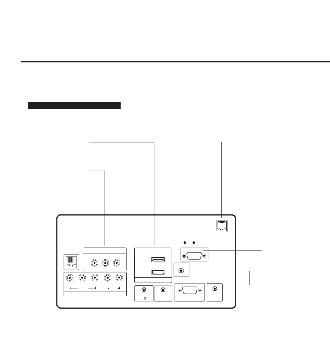
• RJP Available? If you will use a remote jack pack in your system,
set installer item 093 RJP Available to 001 so the RJP function is enabled.
Note: Make RJP connections first then set 093 to 001.
Remote Jack Pack Setup
093 RJP AVAILABLE 001
206-4118
PAGE 18
Remote Jack Pack (RJP) / TV Connections after Commercial Mode Setup
and Cloning Master TV Setup Procedures
Make these connections after commercial mode setup and cloning procedures are complete
HDMI
GAME
CONTROL
COMPONENT IN
VIDEO AUDIO
R
L
RGB IN (PC)
RS-232C IN
(SERVICE ONLY)
UPDATE
RESET
AUDIO IN
REMOTE
CONTROL OUT
SPEAKER OUT
(8 )
PB
YPR
.....
.....
.....
.....
....
..........
..........
2
1
RJP
AV IN 1
VIDEO AUDIO
R
L(MONO)
HDMI/DVI IN
TV-LINK
CFG
(RGB / DVI)
AUDIO IN (RGB / DVI)
RGB/DVI Audio input from
RJP.
HDMI/DVI PORTS
Connect to output jack(s)
from HDMI / DVI RJP.
AUDIO/VIDEO IN 1
Connect to composite
Video/Audio output jacks on
RJP.
RGB IN (PC)
Connection for RGB hookup
from RJP.
REMOTE JACK PACK PORT
Connect to control output
port on RJP.
LAN
Connect to control network.
(Except 32LH240H)
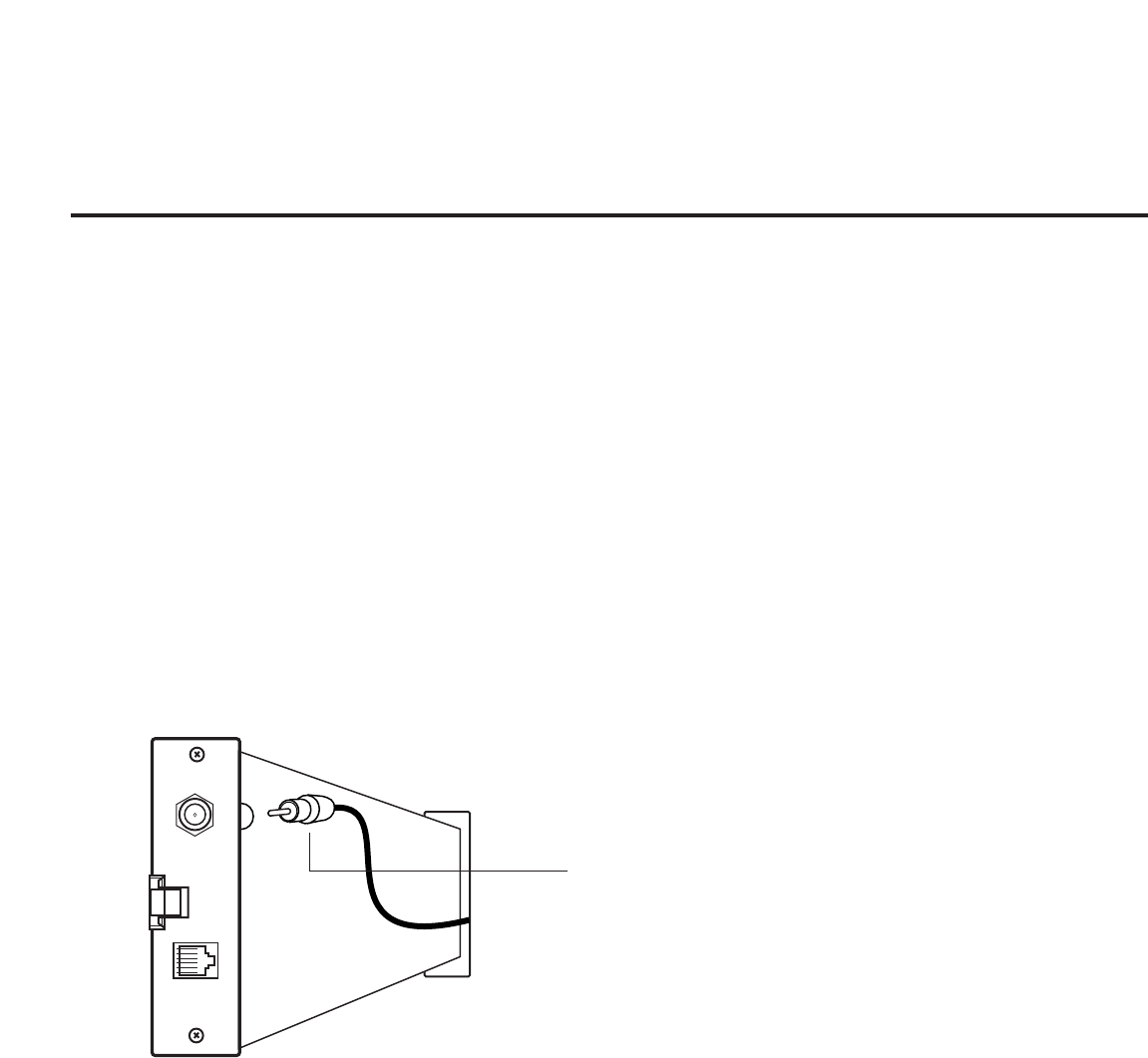
PAGE 19
206-4118
MPI Card Slot / PPV Card Installation
DC IN
ANTENNA IN M.P. I.
M.P. I.
Card Slot
RF CABLE
RF cable needs to be dis-
connected to remove cur-
rent card.
MPI Card Removal / PPV Card Installation
1. Remove the two MPI card retainer screws.
2. Pull out current MPI card far enough so that the RF cable can be detached from the old card.
2. Detach RF cable.
3. Place new PPV card into slot and slide it in far enough to reconnect RF cable.
4. Insert card all the way into the slot making sure it is fully seated into back plane connector.
5. Replace the two card retainer screws.
The MPI card is equipped with an RF jack for antenna/cable signal source connection.
The MPI card slot is also available for installing a PPV (Pay-Per-View) card.
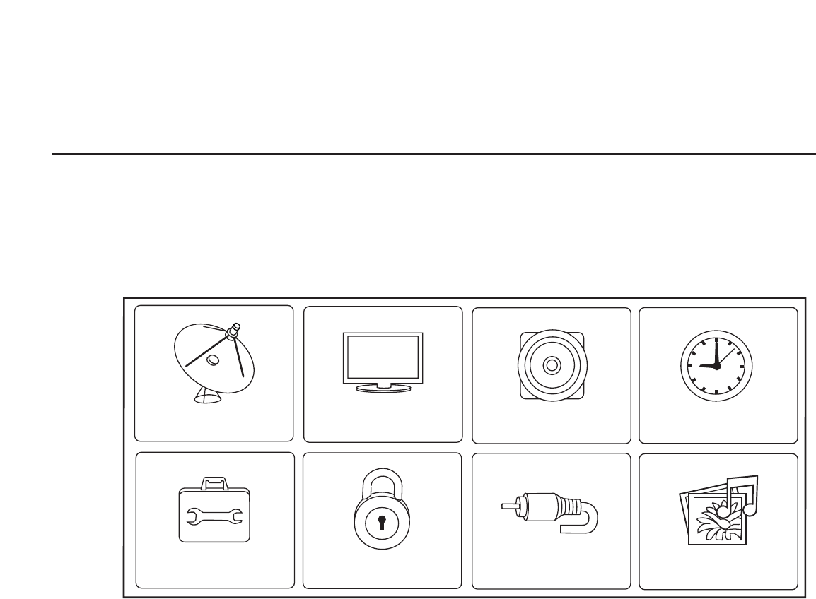
CHANNEL PICTURE AUDIO TIME
INPUT USB
OPTION LOCK
TV Features Configuration Menus Overview
The onscreen menus control the basic TV features
Main TV Menus
The Main TV setup menus control the features of the TV. Set the TV features to the
desired configuration for the end user.
Use the USB port to upgrade TV software.
206-4118
PAGE 20
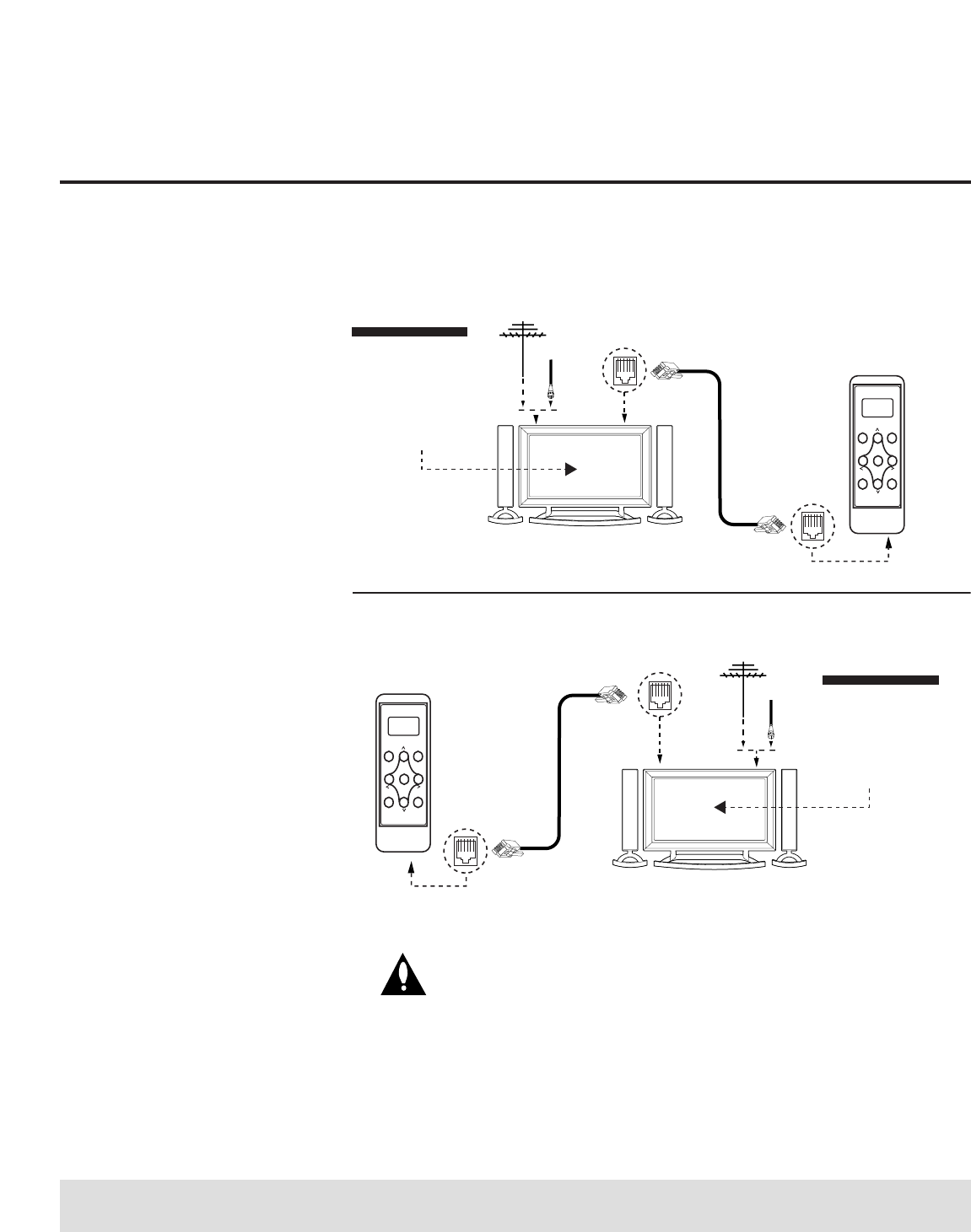
PAGE 21
206-4118
Antenna
(or CATV)
Antenna
(or CATV)
TV Link
Loader-Demo
TLL1100A
Ready
TLL1100A
ENTER
RECEIVE SEND
MENU
MODE
CLONE SELECTION MENU
Selected Bank: CBank X Saved
(1) LEARN FROM TV
(2) TEACH TO TV
(3) SET CLONE CLOCK FROM TV
(4) SET TV CLOCK FROM CLONE
(5) DISPLAY TV SETUP
(6) DISPLAY CLONE SETUP
CLONE CLOCK = 00:00
TV CLOCK = 00:00
THE CLONE IS VERSION V2.2.2
-To change menu items, Press
channel keys or digits.
-To execute item, Press ENTER.
M.P.I. Learning Setup
M.P.I. Teaching Setup
TV Link
Loader-Demo
TLL1100A
Ready
TLL1100A
ENTER
RECEIVE SEND
MENU
MODE
Connections for the TLL-1100A Clone Programmer to Learn the TV Master TV Setup
Notes: It is assumed that the TV is connected to a signal
source, the TV source selected is Antenna (RF) In, the signal is
from an Analog channel, not a digital channel, all equipment is
connected to power and turned on and the TLL Cloner main
menu is displayed on the TV screen, see above.
TLL-1100A Cloning Connections/Learning Setup
Warning: Do not use the TLL-1100A while any PPV card is installed in TV or
clone programmer device will be damaged.
On Master TV
Set up all Master TV features on
the menus and do a Channel
Search. Add Channel and Aux
labels etc. See previous page.
Insert MPI cable into TV MPI port.
On TLL-1100A
1. Turn On the TLL-1100A.
2. Use the Mode button to select
Clone Mode.
3. Use the Left/Right arrow to
select the CBank (1 - 8) to
store the master setup in.
4. Plug the other end of the MPI
cable into the MPI port on the
bottom of the TLL.
5. With the Installer remote con-
trol, select item 1 on TLL menu.
6. Press Enter, to transfer the
Master setup into CBankX on
the TLL. The TLL will copy the
master setup.
7. When learning is done, discon-
nect MPI cable from Master TV.
8. Reconnect TV power cord. Power
the TV On and the master setup
should be resident on the TV.
On Target TV
1. Connect MPI cable from the TLL
to the MPI port on the Target
TV. Assure that the correct
CBank(X) is selected on TLL..
2. With the Installer remote con-
trol select item 2, to Teach the
target TV the master TV setup.
3. Press Enter to begin teaching.
4. When Teaching is done, discon-
nect MPI cable and power the
TV Off. Unplug TV power cord.
5. Reconnect TV power cord.
Power the TV On and the mas-
ter setup should be resident on
the TV.
GGIf an analog channel is not available, tune TV to an Aux source lik AV-1 for cloning purposes.
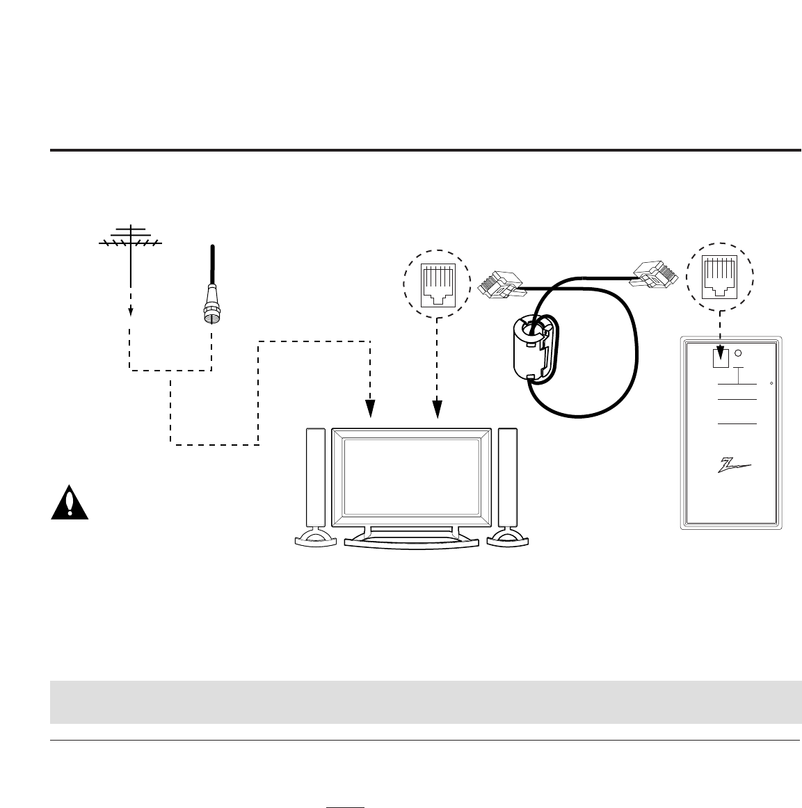
Before you begin cloning...
• The Master TV should be connected to a good, stable signal
from an over-the-air antenna or cable service Analog channel
and connected to power. (See above.)
• Teaching and Learning is only possible between identical
model devices. (However, the LT2002 Clone programmer can
store up to 3 different ‘master’ setups.)
WARNING: Copying a blank or incorrect memory into a TV, STB
or other device will cause the TV, STB or other device to
operate erratically or become inoperable.
• Use an Installer’s remote to operate Learning and Teaching
menus.
• Make sure that the batteries in the Clone programmer are
fresh.
• If batteries are removed, the Clone Clock time will be lost.
• Decide if you want to set the time from the Clone program-
mer or copy the time to the Clone programmer; from a com-
patible TV which has the clock set to the current time.
• Setting the time and transferring it to the Clone or other
device is a separate procedure.
• Follow the connection diagram above to connect the Clone to
a Master TV TV display panel. After learning is complete, to
another identical TV TV display panel to “teach” it the master
setup.
• See the Clone Troubleshooting section to resolve problems.
Turn to the next page to continue Cloning Setup.
QuickSet II Programmer
LT2002
®
Ferrite Core
(TDK, ZCAT
2035-0930)
ZENITH ELECTRONICS CORPORATION, LINCOLNSHIRE, ILLINOIS USA
• heartbeat power on
communications ok
• slow power on
no communications
• green battery ok
• red battery low
Blink pattern
Color
Reset
Status
Indicator
Connect cable to
TV MPI Jack and
follow on screen
instructions
MPI
THE CLONE HAS CONTROL OF THE TV
THE CLONE IS VERSION XX
THE TV IS VERSION XX
THE SW IS REVISION XX
CLONE CLOCK = XX:XX
TV CLOCK = XX:XX
-PRESS ANY KEY TO CONTINUE.
-DISCONNECT CLONE WHEN DONE.
Antenna
or CATV
Master TV
Clone Programmer
Connections for the LT2002 Clone Programmer to Learn the TV Master TV Setup
Notes: It is assumed that the TV is connected to a signal source, the source selected is Antenna (RF) In, the
signal is from an Analog channel, not a digital channel, all equipment is connected to power and turned on
and the LT2002 Clone Programmer main menu (THE CLONE HAS CONTROL OF THE TV) menu is displayed on the
TV screen, see above and next page.
LT2002 Cloning Connections/Learning Setup
Warning: Do not use
LT2002 while any PPV
card is installed in TV or
clone programmer device
will be damaged.
206-4118
PAGE 22
GGIf an analog channel is not available, tune TV to an Aux source lik AV-1 for cloning purposes.
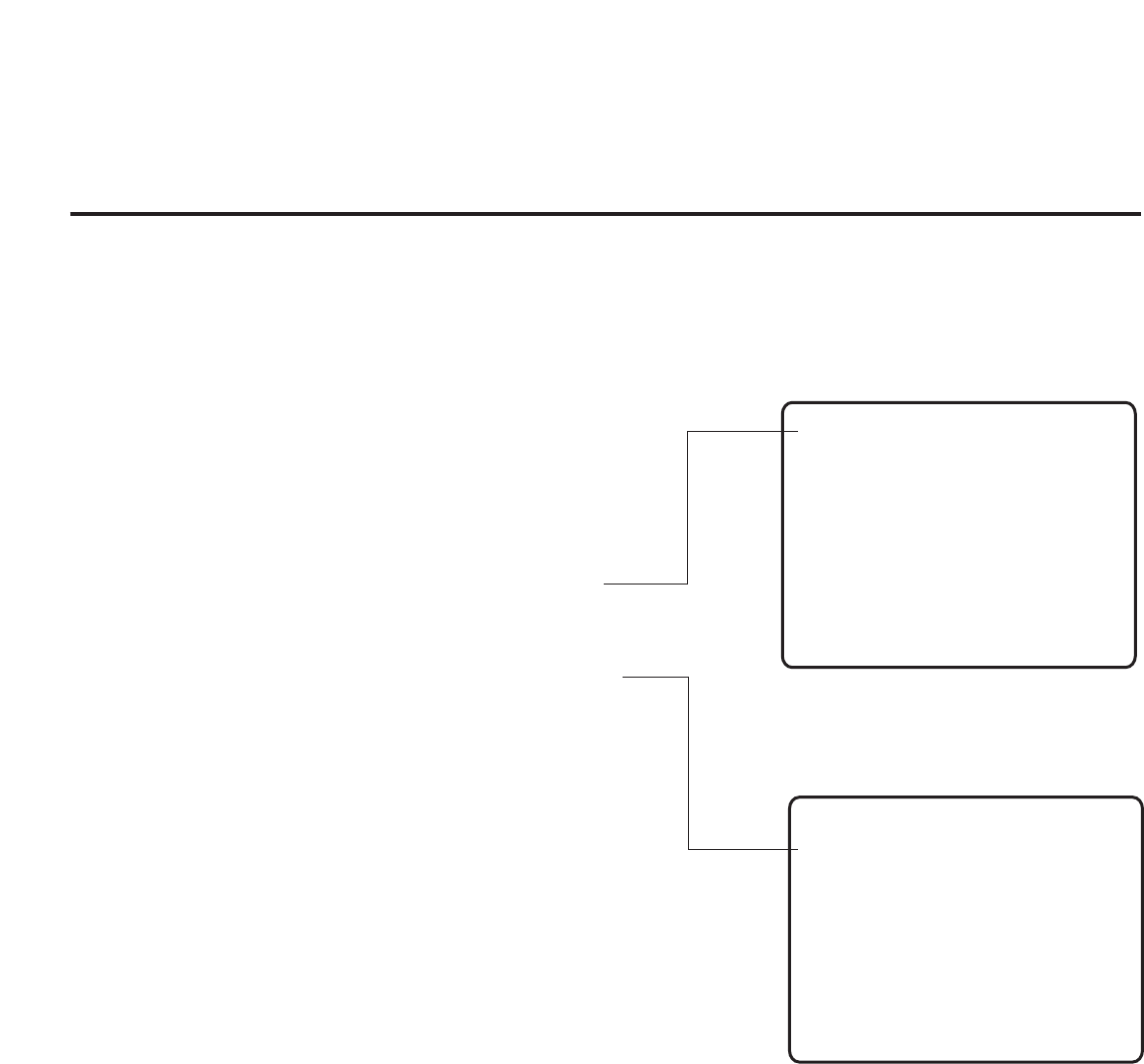
PAGE 23
206-4118
Use MPI Cable to Connect LT2002 Clone Programmer to
Master TV MPI Port
If there is a good connection, “THE CLONE HAS CONTROL OF TV”
message will appear. Press any key on the Installer remote.
Learn Setup from Master TV
Press 1 to select the “LEARN FROM TV” option, then press ON/OFF,
POWER, or ENTER to go to the Memory Bank Selection Menu. Pick the
Memory ”Bank” you want to store the master TV’s setup in by press-
ing either Channel key repeatedly to choose Memory 1, 2 or 3. (If
you choose a Memory “Bank” that has a master device’s setup pro-
grammed into it, that setup will be overwritten by the new master
TV’s setup.) Once the Clone memory bank is selected, press ON/OFF,
POWER, or ENTER. The Clone memory bank you have selected will be
shown. Press ON/OFF or POWER to begin copying the master TV’s
setup.
Set the Clock (Optional)
Set the time on a Master TV’s Clock. (If the time has already been
copied from a TV into the Clone programmer, you can set a master
TV’s clock by copying the time from the Clone programmer.) The
Clone Programmer can copy the current time to both a master TV and
to the Clone’s internal clock; accurate to within one minute. (Another
reason that the Clone programmer should be equipped with fresh,
high-quality alkaline batteries, is for it to keep the time as accurate-
ly as possible.)
Since the Clone Programmer’s time cannot be set directly, the current
time needs to be copied from a Zenith/LG TV equipped with M.P.I.
input capability.
After the time is copied to the Clone programmer, the current time
can then be transferred to another TV. (This can be a master TV, or
another TV which has already had the features set up.)
Instructions for the Clone Programmer to Learn the Master TV Setup
LT2002 Clone Programmer Communication Problems
• A slow flashing green light indicates there are communica-
tion problems between the TV and the LT2002 clone program-
mer. If this is the case, check for a damaged cable, poor con-
tacts, or other connection troubles.
• If the status indicator is red, the programmer batteries are
low and should be replaced. Install 4 high-quality alkaline
AA batteries.
Learning the Master TV Setup
THE CLONE HAS CONTROL OF THE TV
THE CLONE IS VERSION XX
THE TV IS VERSION XX
THE SW IS REVISION XX
CLONE CLOCK= XX:XX
TV CLOCK= XX:XX
-PRESS ANY KEY TO CONTINUE.
-DISCONNECT CLONE WHEN DONE.
CLONE SELECTION MENU
(1) LEARN FROM TV
(2) TEACH TO TV
(3) SET CLONE CLOCK FROM TV
(4) SET TV CLOCK FROM CLONE
(5) DISPLAY TV SETUP
(6) DISPLAY CLONE SETUP
-TO CHANGE MENU ITEMS, PRESS
CHANNEL KEYS OR DIGITS.
-TO EXECUTE ITEM, PRESS ON/OFF,
POWER, OR ENTER
This menu should appear by itself after the
LT2002 is connected to the TV MPI port.
This menu should appear after any key is
pressed on the Installer remote.
LT2002 Cloning Learning Setup
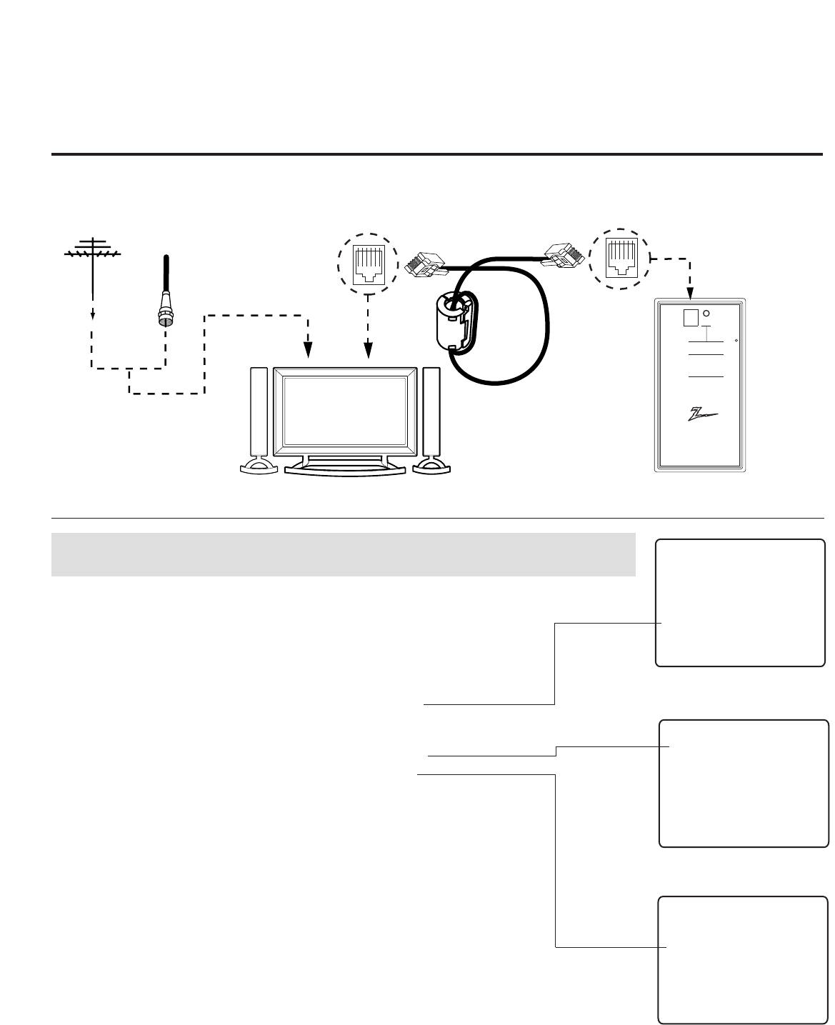
206-4118
PAGE 24
Teach Master TV’s Setup to
the target TV
After learning is complete, remove the M.P.I. cable from the
master TV and connect it to the target TV that you want to
copy the master TV’s setup into. With “THE CLONE HAS
CONTROL OF TV” message displayed, press 2 or use either
Channel key to go to the “TEACH TO TV” option, press ON/OFF,
POWER, or ENTER. Select the LT2002 memory that the new
setup is in. Press On/Off to transfer the new setup and other
information to the new TV. Teaching usually takes 2-3 minutes.
After the “TEACHING COMPLETE” message is displayed, press
any key to return to the Clone menu, then press ON/OFF,
POWER, or ENTER. If finished, detach M.P.I. cable from the
target, newly-cloned TV.
Disconnect TV Power for 15 Seconds
Unplug the AC power cord of the newly-cloned TV from the
power outlet for about 15 seconds to activate the newly-
copied setup.
QuickSet II Programmer
LT2002
®
ZENITH ELECTRONICS CORPORATION, LINCOLNSHIRE, ILLINOIS USA
• heartbeat power on
communications ok
• slow power on
no communications
• green battery ok
• red battery low
Blink pattern
Color
Reset
Status
Indicator
Connect cable to
TV MPI Jack and
follow on screen
instructions
MPI
Ferrite Core
(TDK, ZCAT
2035-0930)
THE CLONE HAS CONTROL OF THE TV
THE CLONE IS VERSION XX
THE TV IS VERSION XX
THE SW IS REVISION XX
CLONE CLOCK = XX:XX
TV CLOCK = XX:XX
-PRESS ANY KEY TO CONTINUE.
-DISCONNECT CLONE WHEN DONE.
Antenna
or CATV
Target TV Clone Programmer
TEACHING IN PROGRESS,
PLEASE WAIT
TEACHING COMPLETE
This display will appear after Teaching
is complete.
This display will appear during
Teaching function.
Teaching the Master Setup to Another TV
Connections for the LT2002 to Teach another TV the Master Setup
CLONE SELECTION MENU
(1) LEARN FROM TV
(2) TEACH TO TV
(3) SET CLONE CLOCK FROM TV
(4) SET TV CLOCK FROM CLONE
(5) DISPLAY TV SETUP
(6) DISPLAY CLONE SETUP
-TO CHANGE MENU ITEMS, PRESS
CHANNEL KEYS OR DIGITS.
-TO EXECUTE ITEM, PRESS ON/OFF,
POWER, OR ENTER
This menu should appear after any key
is pressed on the Installer remote.
Cloning Connections/Teaching Setup
GGIf an analog channel is not available, tune TV to an Aux source lik AV-1 for cloning purposes.

PAGE 25
206-4118
Reset Clone After Static Shock
After replacing exhausted batteries, or if the programmer
behaves strangely after a static shock, use a paper clip or simi-
lar instrument inserted through the small hole marked ”RESET”
to activate the internal reset switch and restore normal opera-
tion. After a reset, check the real-time clock setting. It may be
necessary to reset the Clone Programmer clock from a TV con-
taining the correct time.
Note
The LT2002 programmer is designed to be used with TVs con-
taining the 221-01006 and later processors. Use with earlier TV
sets may give unpredictable results. Processors used before the
221-01006-04 have a limited screen display capability. They
cannot display entire screens as shown in the quick setup
instructions accompanying the LT2002 clone programmer. Use
the printed menu illustrations on the quick setup sheet sup-
plied with the Clone as an aid to making your programming
choices. (Although the menus are not all displayed, the clone
functions all operate normally.)
• After cloning operations are complete, just unplug the LT2002 from the TV.
• If the TV does not display a picture on the TV (blank screen) after a few seconds, just change channels.
Clone Programmer Troubleshooting
Problem Possible Cause(s) Possible Solution(s)
Clone Programmer
Clone copies Setup in • Not enough time to copy - Press Reset on clone programmer, redo teach/learn.
less than 30 seconds entire TV setup. (Teach/Learn should take a minimum of 1 minute.)
Remote does not • Wrong Installer remote. - Only use an LG Installer remote to operate clone programmer
operate clone. with TV.
LED does not blink. • M.P.I. cord not connected. - Connect M.P.I. cord properly, assure good connection.
• TV not turned on. - TV must be powered On for clone to work.
• Weak batteries. - Install 4 fresh AA high-quality alkaline batteries.
Clone menu hard • Weak signal. - Connect TV to a reliable Analog channel signal
to read. source.
No time set. • Time not available. - Set time on a TV, copy time to Clone Programmer.
Clone not working. • Clone programmer - Try a different LT2002 Clone programmer.
problem. - Reset Clone Programmer.
Clone Scans Channels • Clone should only scan - Retry cloning again.
more than once. channels once.
Master and Other TVs
Cloning did not work. • Procedure interrupted. - Wait until procedure complete message is displayed.
• Different TV models. - Cloning is only possible with identical model TVs.
• Step(s) omitted or - Reread pages 7-8-9 to be sure all tasks were performed.
not performed.
Clone time disappeared. • Batteries were removed. - Batteries must remain installed to retain time settings.
New Setup not present. • TV not reset. - Disconnect newly-cloned unit from power for 5 seconds.
Reference: LT2002 Cloning Procedure Troubleshooting
Warning: Do not use LT2002 while any PPV card is
installed in TV or clone programmer will be damaged.
Use the Installer’s Menu to set up or change operational settings.
See more detailed descriptions of the Installer menu items on the following pages...
Accessing the Installer’s Menu
Make sure TV is on. Installer’s menu items can be accessed by using an installer’s remote
control. Just press MENU repeatedly until the TV seems to stop responding, then press 9,
8, 7, 6, then ENTER to access the Installer’s menu. To remove the Installer’s menu, press
ENTER again. Any changes you make will be stored in nonvolatile memory.
The Installer’s menu opens with item 000 INSTALLER SEQ 000. Use the Up/Down arrow
keys to sequence through the available menu items. Or, access an item directly by keying
in the line number, then pressing MENU. For example, to access the Sleep Timer option
which is item 015, press 0-1-5, then MENU. To change a setting, use the Left/Right
arrow keys. Or, enter a value directly.
Using the Installer’s Menu
Items 000 ~ 118 are immediately accessible only upon entering the Installer’s Menu.
Their numbers, descriptions, ranges, factory default settings, and a place for listing any
changes made on-site are given below and on the following pages. Installer menu items
not relevant to this TV series are not present on the Installer menu, therefore some num-
bers are missing. Items 006, 012, 013 etc., will not appear.
Installer Menu Items 000 through 034
Menu Item Function Value Range Default Value Brief Description of Function and Comments
000 INSTALLER SEQ 0 ~ 3 0 Leave default set to 0.
001 POWER MANAGE 0 ~ 7 0 Sets number of hours of no activity before auto shut Off.
002 AC ON 0 / 1 0 Set to 1 to enable auto turn On at power up.
003 BAND/AFC 0 ~ 3 1 Selects Tuning Band: 0=Broadcast, 1=CATV, 2=HRC, 3=IRC
004 STRT CHANNEL 0 ~ 127, 255 255 Channel at turn-on (Set to 255 to tune in last channel before power Off).
005 CHAN LOCK 0 / 1 0 If set to 1, cannot tune from current channel.
007 STRT VOLUME 0 ~ 63, 255 255 Sets Volume level at TV turn-on (Set 255 to retain last volume level).
008 MIN VOLUME 0 ~ 63 0 Sets minimum allowable volume setting.
009 MAX VOLUME 0 ~ 63 63 Sets maximum allowable volume setting.
010 MUTE DISABLE 0 / 1 0 Set to 1 to disable mute function.
011 KEY DEFEAT 0 / 1 0 Set to 1 to disable menu navigation keys on display panel.
015 SLEEP TIMER 0 / 1 1 Set to 1 to enable Sleep Timer.
016 EN TIMER 0 / 1 0 Set to 1 to enable On/Off Timers.
017 ALARM 0 / 1 1 Set to 1 to enable Alarm.
021 V-CHIP 0 / 1 1 Set to 1 to enable V-Chip functions.
022 MAX BLK HRS 0 ~ 99 12 Sets number of V-Chip (Parental Control) blocking hours.
023 CAPTION LOCK 0 / 1 0 Set to 1 to retain caption setting at power Off.
028 CH. OVERIDE 0 / 1 1 If set to 0, limits direct access to favorite channels.
029 OLD OCV 0 / 1 0 Set to 1 to change M.P.I. operation to OCV.
030 ACK MASK 0 / 1 0 If set to 1, changes M.P.I. for some OCV boxes.
031 POLL RATE 20 ~ 169 94 Selects poll rate for M.P.I.
032 TIMING PULSE 186 ~ 227 207 Sets baud rate for M.P.I.
034 CAMPORT EN 0 / 1 1 Set to 1 to enable Video 2 input.
Installer Menu
206-4118
PAGE 26
000 INSTALLER SEQ 000
UPN 000-000-000-000 FPGA E0F1
PTC V1.00.000 CPU V3.06.00
XXLH250H INSTALLER MENU
Typical Installer Menu

Menu Item Function Value Range Default Value Brief Description of Function and Comments
035 COMPPORT EN. 0 / 1 1 Set to 0 to disable HDMI 1. Set to 1 enable HDMI 1
038 YPrPb EN. 0 / 1 1 Set to 1 to enable display panel Component Video 1 input jacks.
039 REAR AUX EN 0 / 1 1 Set to 1 to enable display panel Video 1 input jack.
040 AUTO CAMPORT 0 / 1 1 Set to 1 to automatically switch to Camport. If set to 1, STRT AUX SRCE cannot be set to 2.
046 STRT AUX SRCE 1 ~ 6, 255 6 Sets the starting AUX source.
047 AUX STATUS 0 / 1 0 Set to 1 for M.P.I. AUX source to be reported as a channel number instead of Channel 0.
053 DIS. CH-TIME 0 / 1 0 Set to 1 to disable Channel-Time display.
069 EN. CH-T COL. 0 / 1 1 Set to 1 to enable custom color for the Channel-Time display.
070 FOR. CH-TIME 0 ~ 7 2 Chooses custom foreground color for the Channel-Time display.
071 BCK. CH-TIME 0 ~ 7 2 Chooses custom background color for the Channel-Time display.
073 CH NOT AVBLE 0 / 1 0 If set to 1 and channel override is 0, “NOT AVAILABLE” message is displayed
when directly accessing a channel not in the favorite channel list.
075 REVERT CH 0 / 1 0 If set to 1 and loss of M.P.I. communication occurs, TV tunes to Start Channel.
078 UPN MSB 0 ~ 255 0 User programmable number, most significant byte.
079 UPN MSB-1 0 ~ 255 0 User programmable number, most significant byte - 1.
080 UPN MSB-2 0 ~ 255 0 User programmable number, most significant byte - 2.
081 UPN LSB 0 ~ 255 0 User programmable number, least significant byte.
082 CHKSM ERROR 0 / 1 1 Enforces rigid M.P.I. checksum.
083 HANDSHK TIME 0 ~ 5 5 Relaxes M.P.I. timing to be compatible with PC based Windows-controlled systems.
084 PERMANENT BLK 0 / 1 0 Removes block hours setting for Parental Control and makes block permanent.
087 REAR RGB EN. 0 / 2 / 18 2 Set to 0 to disable RGB1. Set to 2 to enable for PC and Auto Configure always enabled. Set to 18 to
enable for PC and Auto Configure one time only after AC ON.
088 EN NOISE MUTE 0 / 1 1 If set to 1, mutes audio if no signal is present.
090 KEY LOCK 0 / 1 0 If set to 1, keyboard is locked out, IR is still functional.
091 YPrPB2 EN 0 / 1 1 Set to 1 to enable HDMI-2 input.
093 RJP AVAILABLE 0 1 2 5 6 0 Set to 0 to disable. Set to 1, 2, 5 or 6 for HDMI or DVI mode. (See detailed descriptions.)
094 SAP MENU EN 0 / 1 1 Set to 0 to disable feature on Function menu. Set to 1 to enable feature on Function menu.
096 DEF. ASP. RATIO 0 ~ 4 2 Sets default aspect ratio at power up. See detailed descriptions and item 106.
098 START GEM CH 0 ~ 135, 255 255 Sets the stating Gem channel, 255=last channel at power Off.
099 BACK LIGHTING 1 ~ 100 200 Sets the brilliance of the TV picture backlighting.
101 ~ 200, 255 Settings above 101 control dynamic back lighting and disable power saving mode..
102 ATSC BAND 0 ~ 4 4 Selects ATSC band.
103 ATSC TUNE MODE 0 / 1 1 Default 01 for physical channel scan. Set to 0 for Virtual Channel scan.
104 START MINOR CH 0 ~ 255 0 Selects Minor start channel. Set 0 for NTSC. Not 0, sets Minor channel number.
106 ASP RATIO LOCK 0 / 1 0 To retain set aspect ratio on power cycle, set to 1. Set to 0 for default ratio on power cycle.
116 VIDEO MUTE EN 0 / 1 0 Set to 0 for normal, set to 1 for Blank.
117 FACT DEFAULT 0 / 1 0 0=Normal. 1=Loads presets of all above settings.
118 POWER SAVING 1, 3, 7 3 Set to 1 to be powered at b-Lan module. Set to 3 to bo powered at b-Lan module only when TV is powered
on. Set to 7 to be not powered at b-Lan module.
Installer Menu Items 035 through 118
Installer Menu
PAGE 27
206-4118
Note 1: Dependent on item 093 RJP Available setting. (Except 32LH240H)

PAGE 28
Detailed Descriptions of Installer Menu Items
000 - INSTALLER SEQUENCE
Specifies entry sequence to the Installer Menu.
0 = 9876 1 = 4321
2 = 1478 3 = 3698
001 - POWER MANAGE (Power Management)
Determines hours of no activity before automatic shutoff. The POWER
MANAGE function is for saving energy. If set to 0, Power Manage is Off.
Settings range from 0 ~ 7, with 1 ~ 7 representing the hours that the
unit will remain On, unless there has been activity from either the
control panel or remote control.
002 - AC ON (AC Power Switchable)
If set to 1, allows the TV to turn On just by applying AC power.
Pressing the On button is not necessary. This is desirable if the TV is
plugged into a cable box or a power outlet controlled by a wall switch.
Use ADJ Left/Right arrow to choose 0 or 1 where 0 is the default is
Off, and 1 is On.
NOTE: If set to 1 (On), the TV does not respond to On/Off commands
from either the remote or the display control panel, and the SLEEP
TIMER is also nonfunctional.
003 - BAND/AFC (Band/Automatic Frequency Control)
There are 4 possible settings for this option:
0 = Broadcast 1 = CATV
2 = HRC 3 = IRC
If some channels were not found by Auto Tuning (Channel Search),
select the appropriate Band setting here and add the channels using
the Channel Edit option in the Channel Menu.
004 - STRT CHANNEL (Start Channel)
If active, this function allows you to determine the initial channel
number when the TV is turned On. This feature is useful for an in-
house information channel, since the TV would always select that
channel when it is turned On. Setting this to 255 causes the last
channel viewed when the TV was turned Off, to be the tuned to chan-
nel when the TV is turned On again. Note: For a digital Start Channel,
always remember to set item 104 to the Minor Start Channel number.
255 = Last channel 1 ~ 125 = Ch X 0 = Aux
126 Map to Channel 3. 127 Map to Channel 4.
005 - CHAN LOCK (Channel Lock)
CHAN LOCK is ideal if the system must always be on the same channel.
Changing channels with Channel Up/Down or keypad numbers is impos-
sible. Channel Lock is inactive if set to 0 (default).
Generally, this feature is used in connection with START CHANNEL
(Installer item 004) where the start channel may, for example, be set
to 3 or 4. If the start channel is 3, then the TV will remain locked on
Channel 3.
NOTE: For Items 007, 008 and 009
For legacy reasons, the scale used is 0 - 63. The PTC software will
translate this to the 0 - 100 scale used by the TV.
To translate a TV volume level to the installer menu value, use the fol-
lowing formula:
Installer Value = TV Value x 63
100
Enter only the whole number (disregard fractions).
007 - STRT VOLUME (Start Volume)
This function allows the Installer to determine the initial volume level
setting when the TV is turned On. This feature is useful for an in-house
information channel, since the TV would always select that volume
level when it is turned On. The range of values are 0 - 63, 255. If 255
is selected, the current volume level will be retained in memory when
the TV is turned Off; at turn On, the volume level will be automatically
set at the previous or last level.
008 - MIN VOLUME (Minimum Volume)
This function determines the minimum volume level allowable with the
VOLUME (VOL) Up/Down control. In this way, for example, someone
cannot set the volume too low to hear. The value range is from 0 to 63
— change values with ADJ Left/Right arrow. The factory default is 0,
which provides the full range of volume control, if item 009 MAX VOL-
UME is also set to 63. It may be best to set the same value on every
TV.
NOTE: The minimum volume level cannot have a value setting higher
than the MAX VOLUME level (described below).
009 - MAX VOLUME (Maximum Volume)
This function determines the maximum volume level allowable with the
VOLUME (VOL) Up/Down controls. In this way, for example, someone
can not set the volume level high enough to disturb others. The value
range is 0 to 63, with 63 as the default, which gives the user the full
range of volume control, if item 008 MIN VOLUME is also set at 0.
Change values with ADJ Left/Right arrow keys. It may be best to set
the same value on every TV.
NOTE: The maximum volume level cannot have a value setting lower
than the MIN VOLUME level (described previously).
010 - MUTE DISABLE
Enables or disables sound mute function. If set to 1, sound cannot be
muted. If set to 0, sound can be muted.
206-4118
Installer Menu

PAGE 29
206-4118
011 - KEY DEFEAT (Keyboard Defeat)
If set to 1, key defeat prevents the end user from accessing the on-
screen menus with the display front panel—MENU, SELECT, and Left /
Right arrow keys do not function. If set to 0, those keys do function.
NOTE: The menus can always be accessed by pressing MENU on the
remote.
015 - SLEEP TIMER
If set to 1, the SLEEP TIMER feature may be used. If set to 0, the
Sleep Timer is not available.
016 - EN TIMER (Enable On/Off Timers) *
If set to 1, Timer function is available to user and enabled continuous-
ly. Set to 0 to disable On/Off Timers. (Clock must be set in order to
use Timers.)
017 - ALARM *
Gives the installer the option of making the Alarm function available
to the end user. If set to 1, Alarm function is available to end user.
Set to 0 to disable the Alarm function.
NOTE: Clock must be set before the Alarm function will work.
021 - V-CHIP (Parental Control) *
Set to 1 to activate V-Chip (Parental Control); have it available to end
user to filter and control or otherwise restrict programming content
that can appear. Set to 0 to turn V-Chip feature Off, not available to
user; no programming restrictions can be set.
022 - MAX BLK HRS (Maximum Block Hours) *
Sets hours from 0 to 99 for the maximum V-Chip (Parental Control)
block hours. Default setting is for 12 blocking hours.
023 - CAPTION LOCK
Set to 1 to restore previous caption On/Off state after turn Off. If set
to 0, captions are always Off at turn On.
028 - CH. OVERIDE (Channel Override)
If set to 1, the user can select channels with either Channel up/down
or by direct keypad entry. If set to 0, only those channels that are
entered for scanning can be selected.
029 - OLD OCV (On Command VideoTM)
Set to 1 for operation with systems from On Command Corporation.
030 - ACK MASK
M.P.I. Communication Parameter. Leave at default setting unless
changed by Pay-Per-View provider. When set to 1, changes M.P.I. for
some OCV boxes.
* Only affects Function Menu if enabled by some PPV providers.
031 - POLL RATE
M.P.I. Communication Parameter. Selects Poll Rate for M.P.I. Leave at
default setting unless changed by Pay-Per-View provider. Step size of
16 ms.
032 - TIMING PULSE
M.P.I. Communication Parameter. Leave at default setting unless
changed by Pay-Per-View provider. Sets baud rate. Step size of 4.3 uS.
034 - CAMPORT EN. (Camera Port Enable)
Set to 1 to enable Video 2 input on display panel. If set to 0, Video 2
input on display panel is not functional.
NOTE: S-Video overrides Video jack.
035 - COMPPORT EN. (Computer Port Enable)
Enable/disables display panel HDMI1 input jack. Set to 0 to disable
HDMI 1. set to 1 to enable HDMI 1.
NOTE: The setting above is ignored if Installer item 093 RJP AVAIL-
ABLE, is set to 1.
038 - YPrPb EN. (Rear Component Video Enable)
Set to 1 to enable display panel rear Component Video input jacks.
Set to 0 to disable display panel rear Component Video input jacks.
039 - REAR AUX EN. (Rear Aux Enable)
Set to 1 to enable display panel rear AUX (Video 1) input.
Set to 0 to disable display panel rear AUX (Video 1) input.
Note: S-Video overrides Video.
040 - AUTO CAMPORT
Set to 1 to automatically switch to Camport when equipment is con-
nected to front Video input.
Set to 0 to disable front Video automatic source selection.
NOTE: If set to 1, 093 RJP Available is automatically set to 0.
046 - STRT AUX SRCE (Start Aux Source)
Sets the starting AUX source. At power up, TV will tune to starting Aux
source if item 004 Start Channel is set to 0.
If item 093 RJP Available is set to 0 and item
040 Auto Camport is set to 0:
1 = Video 1 4 = RGB 255 = Last Aux
2 = Video 2 5 = HDMI 2
3 = HDMI 1 6 = Component
If item 093 RJP Available is set at 1:
2 = Video 2 5 = HDMI 2 6 = Component
If item 040 Auto Camport is set to 1:
1 = Video 1 5 = HDMI 2
3 = HDMI 1 6 = Component
4 = RGB
Installer Menu

PAGE 30 206-4118
Installer Menu
047 - AUX STATUS
Set to 1 for M.P.I. AUX source to be reported as a channel number
instead of channel 0. Set to 0 to disable AUX identification change.
Controls M.P.I. status channel response for AUX inputs.
053 - DIS. CH-TIME (Disable Channel-Time)
Set to 1 to disable the Channel-Time display, Channel-Time display will
not appear.
Set to 0 to enable the Channel-Time display.
069 - EN. CH-T COL. (Enable Channel-Time Custom Color)
Set to 1 to enable custom color for the Channel-Time display.
Set to 0 to disable custom color for the Channel-Time display.
070 - FOR. CH-TIME (Channel-Time Display Foreground Color)
Set according to Color Chart.
0 = Black 3 = Yellow 6 = Cyan
1 = Red 4 = Blue 7 = White
2 = Green 5 = Violet
NOTE: If foreground and background color are the same, menu back-
ground is transparent.
071 - BCK. CH-TIME (Channel-Time Display Background Color)
Set according to Color Chart.
0 = Black 3 = Yellow 6 = Cyan
1 = Red 4 = Blue 7 = White
2 = Green 5 = Violet
NOTE: If foreground and background color are the same, menu back-
ground is transparent.
073 - CH NOT AVBLE (Channel Not Available)
If set to 1 and item 028 CHANNEL OVERRIDE is set to 0, “NOT AVAIL-
ABLE” message is displayed when directly accessing a channel not in
the channel scan list available in memory.
075 - REVERT CH (Revert to Start Channel)
If set to 1 and loss of M.P.I. communication occurs, TV automatically
tunes to the specified Start Channel.
078 - UPN MSB (UPN Most Significant Byte)
User programmable number, most significant byte readable by M.P.I.
command. Note: Not linked to serial number.
079 - UPN MSB-1 (UPN Most Significant Byte-1)
User programmable number, most significant byte-1 readable by M.P.I.
command. Not linked to serial number.
080 - UPN MSB-2 (UPN Most Significant Byte-2)
User programmable number, most significant byte-2 readable by M.P.I.
command. Not linked to serial number.
081 - UPN LSB (UPN Least Significant Byte)
User programmable number, least significant byte readable by M.P.I.
command. Not linked to serial number.
082 - CHKSM ERROR (Checksum Error)
Enforces rigid M.P.I. checksum validation.
Set to 1 for validation.
Set to 0 to disable (does not check checksum on M.P.I. async port).
SPI is always checked.
083 - HANDSHK TIME (Handshake Time)
Adds an additional delay to the handshake time which is 64 msec,
thus relaxing M.P.I. timing requirements to be compatible with PC
based Windows controlled systems, range is 0 - 5.
(Timeout = 25.5MS + [25.5 MS* Handshake time]).
084 - PERMANENT BLK (Permanent Block)
Allows Lock (Parental Control) blocking schemes to be permanent by
disabling the blocking hours function.
Set to 1 to install Parental Control restrictions permanently.
Set to 0 for user-specified hours control of blocking schemes.
087 - REAR RGB EN. (Rear RGB Enable)
Controls access to rear RGB input on TV.
Set to 0 to disable RGB input.
Set to 2 to enable for PC and Auto Configure always enabled.
Set to 18 for Auto Configure one time only with power cord removal
and reinsertion.
088 - EN NOISE MUTE (Enable Noise Mute)
If set to 1, audio mutes if no signal is present.
090 - KEY LOCK
If set to 1, display panel keyboard is locked out, not available to end
user. IR receiver remains functional.
091 - YPrPb2 EN. (HDMI2 Enable)
Set to 0 to disable display panel HDMI2 input.
Set to 1 to enable DTV mode. Set to 2 to enable PC mode.
Detailed Descriptions of Installer Menu Items
206-4118 PAGE 31
093 -RJP AVAILABLE (Remote Jack Pack Available)
0 = Remote jack pack is not available or disabled.
1 = Legacy Model RJPs: HDMI Mode
Enables RJP when an HDMI cable is inserted into RJP. Video is from
HDMI. Audio stream is expected from HDMI source. If no audio is pre-
sent, no audio will be heard.
2 = Legacy Model RJPs: DVI Mode
Enables RJP when an HDMI cable is inserted into RJP. Video is from
HDMI however, Audio is from selected audio source, based on the RJP’s
audio hierarchical priority.
5 = Scaler Model RJPs: HDMI Mode
Enables RJP when an HDMI cable is inserted into RJP. Video is from
HDMI. Audio stream is expected from HDMI source. If no audio is pre-
sent, no audio will be heard.
6 = Scaler Model RJPs: DVI Mode
Enables RJP when an HDMI cable is inserted into RJP.
Video is from HDMI however, Audio is from selected audio source,
based on the RJP ’s audio hierarchical priority.
Notes:
See Reference section, RJP Input Hierarchy and RJP Models page.
If set to 1, 2, 5 or 6, item 040 Auto Camport is automatically set to 0.
Settings 1, 2, 5 and 6 allow the lodge staff to customize each TV ’s
RJP setup based on customer requirements.
094 - SAP MENU EN (2nd Audio Program)
Set to 1 to enable SAP feature on Function menu, if Function menu is
available.
Set to 0 to disable SAP feature on Function menu, if Function menu is
available.
096 - DEF. ASP. RATIO (Default Aspect Ratio)
Selects default aspect ratio at power up, see settings below.
Set to 0 for “Set By System”.
Set to 1 for 4:3.
Set to 2 for 16:9 (Factory Default).
Set to 3 for ‘Just Scan’
Set to 4 for Zoom
099 - BACK LIGHTING
Sets the TV screen brightness at power up, see settings below.
Default setting is 200.
1 - 100 Static Backlighting.
(1 = Dimmest picture, 100 = Brightest picture.)
101 - 200 Dynamic Backlighting.
(101 = Dimmest picture, 200 = Brightest picture.) If settings are above
101, the TV automatically controls backlighting depending upon the
picture level of the current program.
set to 255, to disable power saving mode.
102 - ATSC BAND
Sets up TV to receive different types of incoming signals:
0=Broadcast, 1=CATV, 2=HRC, 3=IRC, 4=Same as NTSC.
103 - ATSC TUNE MODE
Sets ATSC tuning mode: Default set to 1 for Physical channel scan.
Set to 0 for Virtual Channel scan.
104 - START MINOR CHANNEL
Sets XX-XX minor start channel number at power up: 0=NTSC. If not 0,
number selected is the Minor start channel number.
106 - ASP RATIO LOCK (Aspect Ratio Lock)
Set to 1 to retain previous aspect ratio with power Off.
Set to 0 to retain default aspect ratio with power Off. See item 96
Default Aspect Ratio above.
116 - VIDEO MUTE EN (Video Mute Enable)
Set to 0 for normal.
Set to 1 for blank.
117 - FACT DEFAULT (Factory Default)
Set to 0 for normal.
Set to 1 to load presets to all of the previous item set-
tings.
WARNING: Setting this to 1 will reload the factory defaults
and clear the channel list including erasing any assigned
Channel Icons and custom channel Labels.
118 - Power Saving (Except 32LH240H)
Default is set to 3. When TV is in Standby mode, MPI card slot is
powered by Standby power supply and embedded BLAN is not pow-
ered. When TV is in Power On mode, MPI card slot is powered by
main 12V power supply and embedded BLAN is powered. Note, TV
must be powered on in order to communicate with the embedded
BLAN module for configuration and control.
1 = MPI card slot Standby mode power provided from Standby
power supply and embedded BLAN is always powered on.
3 = MPI card slot Standby mode power provided from Standby
power supply and embedded BLAN only powered on when TV is
powered on.
7 = MPI card slot Standby mode power provided from Standby
power supply and embedded BLAN always powered off.
Installer Menu

PAGE 32 206-4118
IMPORTANT INSTALLER SETUP INFORMATION! PLEASE READ THE FOLLOWING...
To set up a master TV you will need to know how to
enter the TV Installer menu and make changes to
the default values as required. If necessary, famil-
iarize yourself with the TV Installer menu and how
to make and save changes in the menu, before attempting to
clone the TV Master TV setup.
You will also need an LG Installer remote control similar to
the one shown in the front of this manual. The installer remote
must have a “Source” button or its equivalent. The remote
shown in this manual has a “INPUT” button -- this button
serves the purpose of a Source button.
Finally, the TV’s clonable features need to be set up. This is a
critical step. If the Master TV display panel’s clonable features
like adding channel icons or channel labels, digital font options
etc., are not correctly added, then the cloned TVs will all have
problems.
As the cloning procedure is being performed, specific steps
need to be done at the indicated times to achieve the desired
result. Be sure to do each task as indicated. If a procedure or
step is left out or not performed completely, cloning may not
work. At each step, pay attention to assure the TV screen shows
the proper message when cloning. If the message indicated
does not appear, there is a problem with that step and cloning
may not be successful. Cloning is only possible when the signal
source is an Analog channel, not a digital channel.
Reference: Detailed Instructions For Making A Master TV
Making a Master TV
Detailed Instructions
The following describes the procedure for preparing a Master TV
for cloning and the procedure for adding Channel Icons and/or
Labels.
Note 1: Disconnect all Aux inputs. Under certain conditions,
Auto Tuning Channel Search is disabled if there is an Aux input
active.
Note 2: Under certain conditions, changes to the input mode of
the RGB inputs will not take effect until the power is cycled (TV
is turned Off and On). To avoid confusion, disconnect all RGB
inputs before entering the Installer menu.
1. Enter the TV installer menu.
a. Reset the internal controller to factory default by access-
ing installer menu item 117 FACT DEFAULT, set it to 1 and
press “ENTER”. The value will change back to 0 after the TV’s
internal controller has been restored to factory default con-
dition. This step will ensure that the TV channel memory will
be the active channel list. Check the Status LED. If it is
blinking rapidly then the TV channel map is in use.
b. Within the Installer menu, set the Installer menu items to
the configuration required of your institution.
c. It is important to set the tuning band at this time, see
Installer menu item 03 BAND/AFC.
d. Set Installer menu item 28 – CH OVERIDE to 001 to allow
access to the Auto Tuning and Ch. Edit features in the
Channel Menu. Exit the Installer menu.
2. Access the Master TV menus and set the clonable options on
the menus to the desired configuration. Refer to the
Clonable Menu Features Chart in this manual.
3. Run Auto Tuning to find analog and digital channels.
4. Enter the Channel Edit menu and edit the channel lineup to
include the Free-To-Guest Channels only.
5. Assign ICONs to the channels using the Channel Label Menu.
Note: You can add Channel ICONS typically network logos
like ABC, NBC, PBS etc. in this step. Or, in Step 7, add
Channel ICONS or labels for channels without Icons.
6. Transfer the TV setup: Enter the TV installer menu. Press ‘2’,
‘5’, ‘5’, ‘MENU’ to start the transfer of the TV’s setup to the
internal controller. Once the transfer is complete, the sys-
tem will exit the Installer menu. Check the Status LED inside
the TV. It should be blinking slowly (1 blink per second).
7. Edit/Add Channel ICONs and Channel Labels as needed.
Enter Installer menu. With menu displayed, press 2-5-4 +
MENU. See next page for detailed instructions:
- Editing/Adding Channel ICON and Labels on Master TV
- Changing a Channel’s ICON on Master TV
- Changing/Adding Channel Labels on Master TV
- Changing Source Labels on Master TV
8. Verify Master TV setup and feature configuration:
• Did you add Channel ICONS?
• Did you add Channel Labels?
• Did you add Source Labels?
• Did you adjust all TV menu options as required?
After verifying master setup, enter the TV Installer menu and
set Installer menu item 28 CH OVERIDE to 000. Press ENTER
to remove and exit the Installer menu.
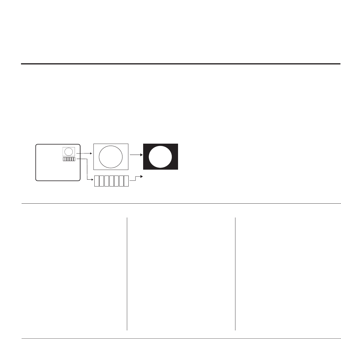
206-4118 PAGE 33
Changing a Channel’s ICON on
Master TV
1. With Channel Up/Down, select the
channel you want to change the
Icon for.
2. With the Right or Left ADJ arrow,
select the thin letter ‘I’ on the
channel ID display.
3. With the Up or Down arrow, select
the desired ICON you want to
appear to identify the channel. (If
you know the ICON number, enter
the number followed by Enter /
Select.)
4. Proceed with Changing/Adding
Labels or go to the next channel.
Changing/Adding Channel Labels
on Master TV
1. Channel Up/Down to select the desired
channel.
2. Press the Right or Left ADJ arrow
repeatedly until the numbers 1 to 7
show up. The number shows the posi-
tion of the character that can be
changed. Number 1 is the first charac-
ter, number 2 the second character
and so on.
3. With the Up or Down arrow, select the
desired character.
4. Proceed to the next number position
or use Channel Up/Down to go to the
next channel.
Changing Source Labels on
Master TV
1. Press “INPUT” to select the desired
Aux input source; A/V 1, A/V 2, HDMI
Component, RGB etc.
2. Press the Right or Left arrow repeated-
ly until the numbers 0 to 9 shows up.
The number shows the position of the
character that can be changed.
3. Use the Up or Down arrows to select
the desired character.
4. Press “INPUT” for the next Aux source
or proceed with Changing Icon or
Changing/Adding Labels. Press Ch
Up/Down to return to channels.
• CHANNEL Up/Down - Tunes in the next channel in scan.
• Left/Right Arrows - Select the item to change. If “I” is
shown, the ICON can be changed. If a number is shown, it
indicates the position of the character that can be changed.
• Up/Down Arrows - Select the ICON or the character to be
displayed. Tip: Arrows can be held down for fast scrolling.
• 0 – 9 - Use to enter the index number of the ICON, if known.
• ENTER/SELECT - Changes the ICON after the number has
been entered.
• INPUT - Changes the Aux input label. (“Source” on the
remote shown in this manual is INPUT.)
• MENU - Exits the editing process.
Installer Remote Control Key Functions for Master TV Channel Editing/Labeling Menu
Adding Channel Icons and Labels in the 2-5-4 + Menu Mode
Reference: Procedures for adding Channel Label Icons/Custom Channel Labels
(2-5-4 + MENU Mode)
Editing/Adding Channel ICONs and/or Labels
If there is no pre-assigned ICON, you can make a custom chan-
nel label of up to 7 characters to help in identifying the chan-
nel or network. At your option, channel labels can also be
added in addition to a pre-assigned ICON. You may also add
labels for the Aux input sources to clearly identify the devices
that are connected to the Aux inputs.
Editing and adding the labels can only be done if there are
channels entered into the TV’s channel map either by using the
method described in item 6 (page 18), by cloning or by the use
of the master remote control from the PPV provider.
Note: A blank letter space is available between ‘Z’ and ‘!’.
To Do Channel Editing/Labeling, Proceed
as Follows
1. Enter TV Installer menu.
2. Once the installer menu appears, press ‘2’, ‘5’, ‘4’,
‘MENU’. This enters the channel label editing mode.
Add your channel icons and channel labels in this
menu, see below. (You can do this more than once.)
3. To exit the menu when done press “MENU”.
1234567
XYZ
XYZ
XYZ
NETWORK
(Icon)
(Label)
Procedure for Checking Software Version
The software version of the TV may be checked by accessing the Installer Menu.
To do this, press MENU repeatedly until the menu display ceases to respond to MENU key presses.
Then, press "9", "8", "7", "6", "ENTER". Press ENTER again to remove Installer Menu from screen.
Typical Installer Menu
000 INSTALLER SEQ 000
UPN 000-000-000-000 FPGA E0F1
PTC V1.00.000 CPU V3.06.00
XXLH250H INSTALLER MENU
PAGE 34 206-4118
Reference: Clonable Menu Features
Notes
• Picture Menu and other menu settings shown above are not clonable on all TVs.
End user has access to Picture, Sound and Ratio on user remote control.
• Menu options vary between Analog / Digital channels and Aux Sources.
Menu /Sub Menu Features
Installer Menu
Installer Item settings
Channel
Auto Tuning (Channel Lineup)
Channel Edit
Channel label
Picture
Aspect Ratio
Picture Mode
Advanced Control
Audio
Auto Volume
Clear Voice
Sound Mode
Balance
Clonable Menu Features
Audio Contd.
Treble
Bass
SRS TruSoundXT
TV Speaker
Option
Language
Caption
Caption Mode
DTV Captions Style - Style
DTV Captions Style - Size
DTV Captions Style - Font
DTV Captions Style - Text Color
DTV Captions Style - Text Opacity
DTV Captions Style - BG Color
DTV Captions Style - BG Opacity
DTV Captions Style - Edge Type
DTV Captions Style - Edge Color
Lock
Movie Rating
TV Rating – Children Age
TV Rating – Children Fantasy
Violence
TV Rating – General Age
Input Block
Time
Auto Clock
Manual Clock
Off Time
On Time
Auto Off
CPU Version
PTC Version
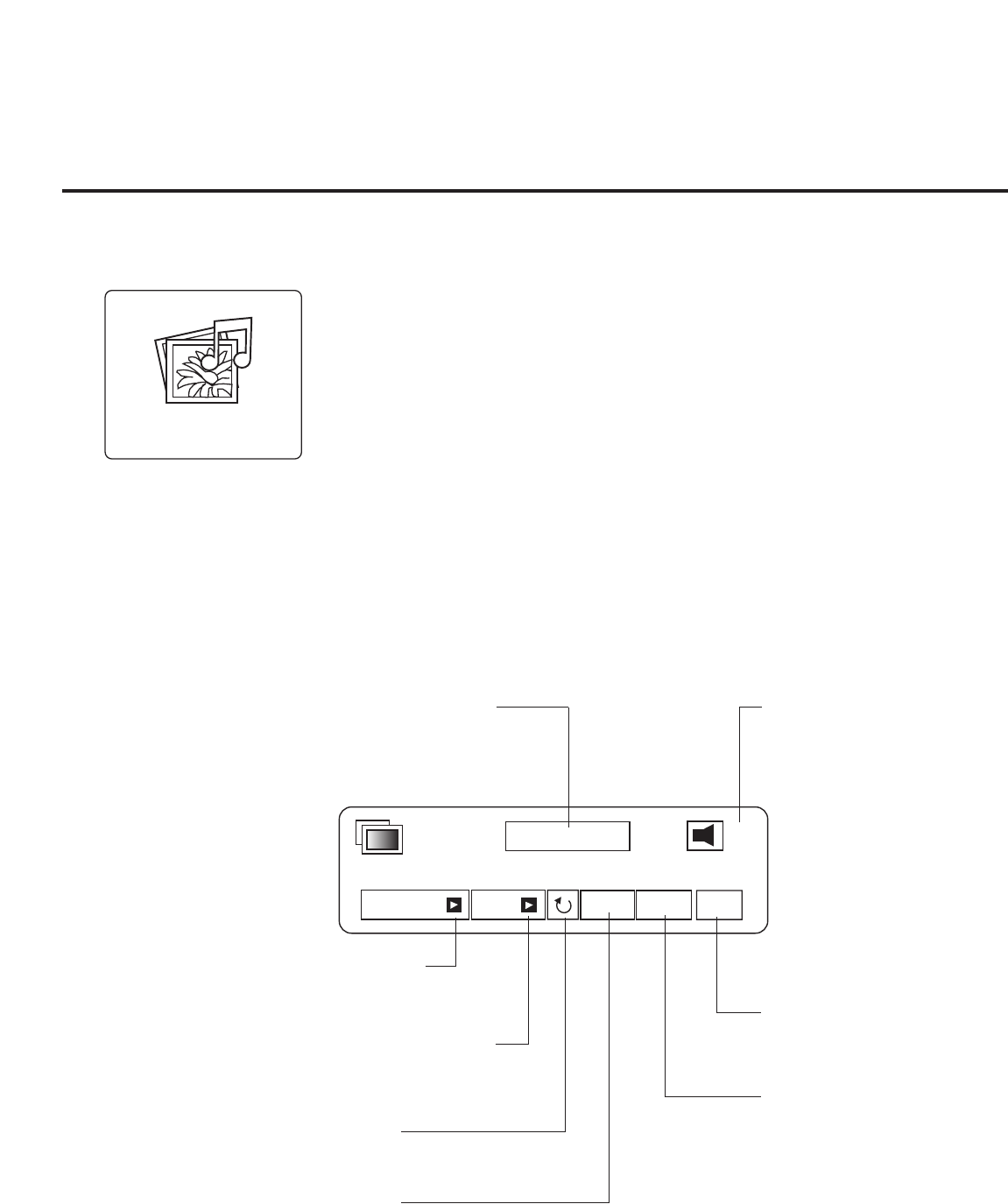
PAGE 35
206-4118
USB End User Features
Slideshow
Toggles slideshow
On and Off.
Delete
Removes slide from slideshow.
Rotate
Rotates picture.
Back Ground Music
Toggles selected music
file On and Off.
USB
USB Menu features Picture Slideshow with or without Music accompaniment
USB Device Setup
On the USB device, load Photo and Music files e.g. MP3. Insert USB device into USB port on
TV side jack panel. Press Menu and select USB option, press Enter.
Note: Windows .wma files are not usable.
View Pictures
Select USB Icon and press Enter. Select Photo List option and press Enter. Select Folder
photos are in. Press Enter. When photo list appears, choose Photo and press Enter.
View Picture with Music
Select USB Icon and press Enter. Select Music Folder option. Select Music List and select
Play with Photo. Select music MP3 file and press Enter.
Listen to Music MP3 Files
Select USB Icon and press Enter. Select Music List option and press Enter. Select Folder with
Music MP3 files. Press Enter. Adjust Volume to comfortable listening level.
Slideshow BGM Option
Delete Hide
Slideshow 1 / 79 9
Option
Press to access available
options. Selects slideshow
playback speed.
Hide
Removes menu from screen.
Press Enter to display again.
Slide Being Shown
Indicates present slide being
shown and number of slides
available.
Sound Level
Indicates volume setting.
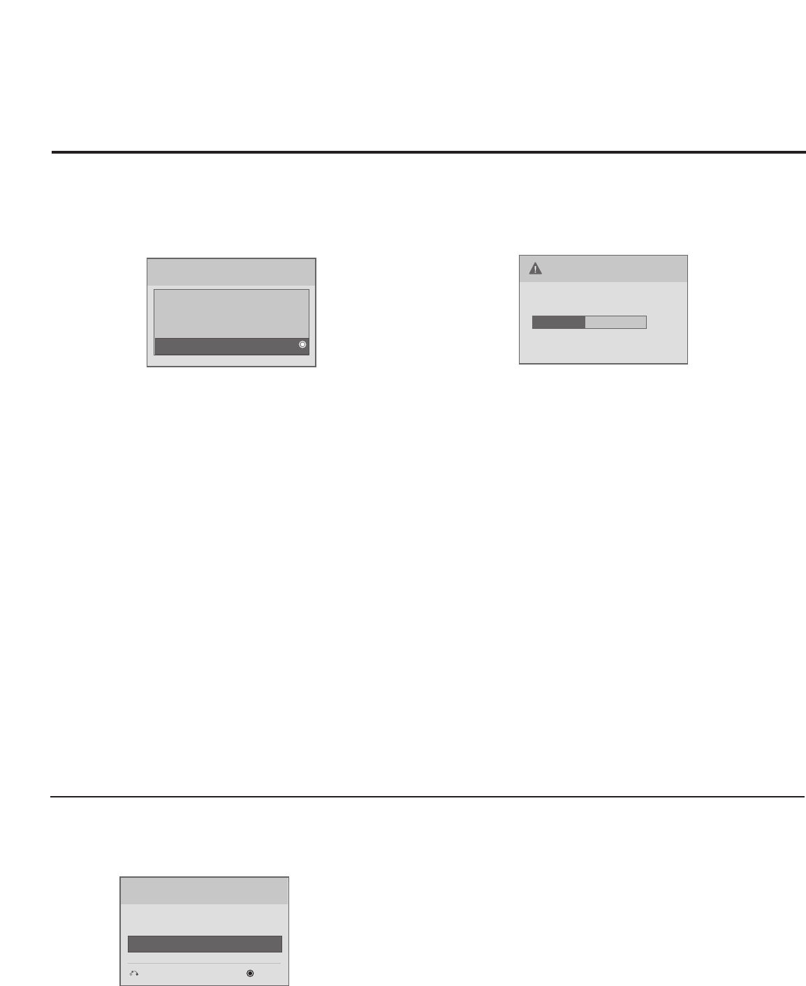
PAGE 36 206-4118
Reference USB Cloning: Master TV Profile Setup-Learning
On Master TV, Create Profile and Learn
1. Set up all Master TV features on the menus and do
a Channel Search.Add Channel and Aux Labels etc.
Do 255+menu on Installer Menu to save current TV
into flash memory.
2. Plug USB memory card into the USB In port on
Master TV.
3. Press Menu key to open Main menu. Highlight the
Option icon.
4. Press the Left arrow key once, the Option icon on
left side of menu will be highlighted.
5. Press number key ‘7 ’a total of 7 times.
6. Access the “Learn From TV “ option.
a. First, Expert Download Menu page will not show
the “Learn From TV ”. In order to make “Learn
From TV available, key in the password which is
used to enter Installer Menu. Example 9-8-7-6.
b. By pressing up/down arrow keys (if there is other
menus), place the cursor on Learn From TV, then
press Enter Key.
7. Using Up/Down arrow key,highlight “Learn From
TV ”, then press Enter.
8. To identify the profile from others, you can
change the last 5 digits. Key in a custom file
name, then press the Enter key.
9. The Learning status will be shown on progress bar.
As soon as learning the current profile is com-
plete, a message will appear on screen indicating
the learning process is done.
10. Remove the USB memory card.
Notes
• Do not remove TV power cord or USB memory card while
Learning, doing so might harm your USB memory card.
• Do not remove TV power cord or USB memory card while
Teaching,doing so may cause the T V t malfunction.
• You are allowed to edit the file name, however, a file with
edited contents will not be recognized.
• Since clock data is copied into USB memory card as numeric
data,the time difference between teaching and learning is
not automatically adjusted. Either set the clock manually, or
use Auto Clock set on TV main menu.
Optional: Edit / Change File Name
If necessary, the file name can be edited or changed.
USB Download Menu
Upgrade TV Software
Upgrade PTC Software
Teach To TV
Learn From TV
Learn From TV
XX250H-UA00001.TLL
Select the file name and press OK to start.
E
E
Previous
Enter
Learn From TV
UPGRADING...
48 %
Do not unplug!
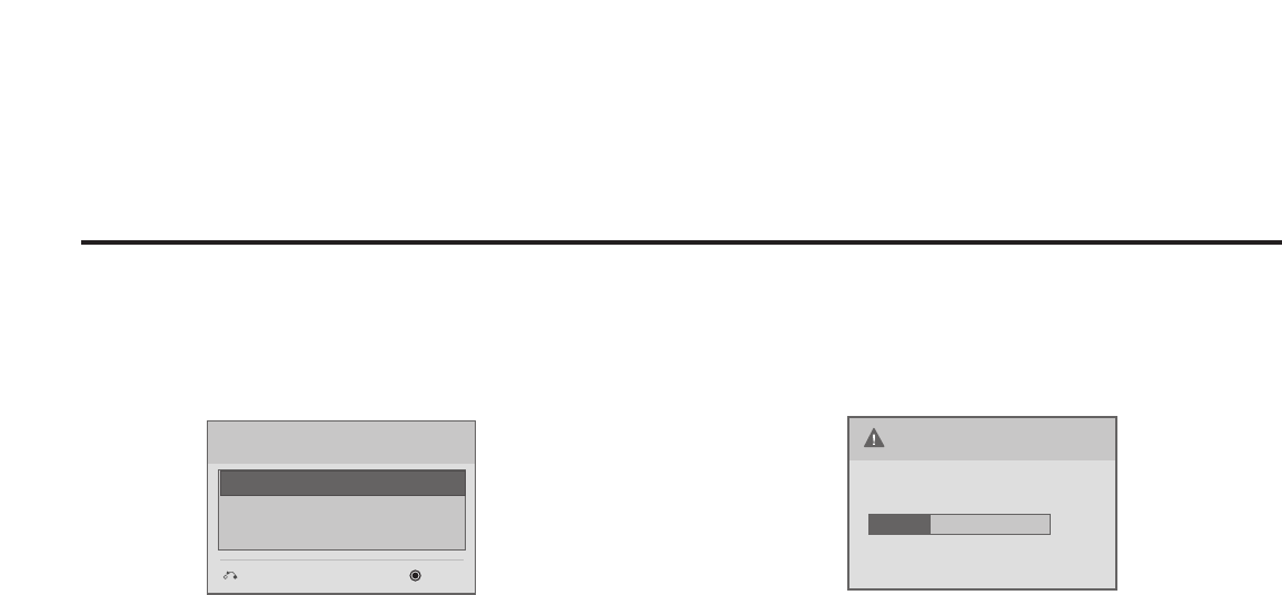
PAGE 37
206-4118
Reference USB Cloning: Master TV Profile Setup-Teaching
1. Plug USB memory card with Master TV Profile
setup into Target TV USB input port.
2. Press Menu key to open Main menu and then
highlight the Option Menu icon.
3. Press the Left arrow key once, this will highlight
the Option icon on left side of menu.
4. Press number key ‘7 ’, a total of 7 times.
5. Using the Up/Down arrow key, select ‘Teach to TV’,
then press Enter key.
6. Use Up/Down arrow keys to navigate through
profiles. Select the profile that you want to install
by highlighting it and pressing the Enter key.
7. Teaching progress will be shown on the progress
bar. As soon as teaching is done, a message will
appear indicating that the teaching process has
been completed.
8. When Teaching is done, remove the USB memory
card and unplug TV power cord.
9. Reconnect TV power cord. Power the TV On and
the master setup should be resident on the TV.
On Target TV, Teach Master TV Profile
Teach To TV
XX250H-UA00001.TLL
Previous
Enter
Teach To TV
UPGRADING...
39 %
Do not unplug!
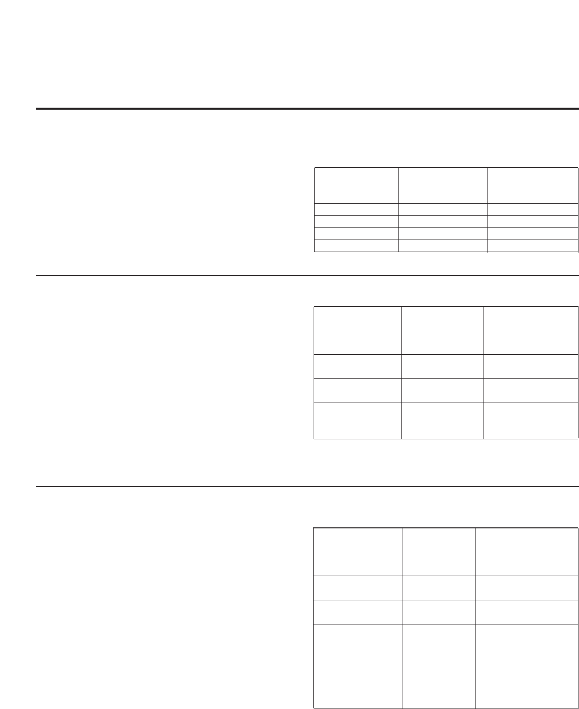
PAGE 38 206-4118
TV Camport Auto Sense Operation
The CAMPORT Auto Sense function is enabled when:
1. Installer Menu Item 34, CAMPORT EN is set to 1 AND
2. Installer Menu Item 40, AUTO CAMPORT is enabled (1).
Selectable= Can be accessed with INPUT key, direct access, etc.
Auto Sense= Switches to this input when connector is inserted.
The camport (Side Video) has the highest priority and will over-
ride any commands including tuning to the Start Channel.
CAMPORT (Front Video) Functionality Control
Item 34 Item 40 Front Video
CAMPORT EN AUTO CAMPORT Operation
0 0 Disabled
0 1 Disabled
1 0 Selectable
1 1 Auto Sense
CAMPORT Operation (Stand-Alone)
When Camport Auto Sense is enabled as above, the TV’s source
will switch to the side video aux source whenever a plug is
inserted into any of the side video panel inputs (either com-
posite Video or S-Video).
When the plug is removed, the TV will switch back to the previ-
ous channel or input source that the TV was using before the
plug was inserted. However, if any direct access to an RF chan-
nel or Aux channel is requested while the camport is active,
then, when the camport plug is removed, the TV will switch to
the last requested channel. Source changes using any Source
Keys (INPUT) are ignored. Channel Up/Channel Down and
Flashback Commands are not direct access tuning commands
and they are also ignored.
Previous State Operation State
Before Inserting While CAMPORT Upon Removal
CAMPORT Is Active Of CAMPORT
Aux or RF Channel None Previous Aux
or RF Channel
Aux or RF Channel Direct Access Last Requested
RF or Aux Channel
Aux or RF Channel Ch Up/Down, Previous Aux
Flashback or RF Channel
and TV/AV Keys
CAMPORT Operation (PPV)
The operation will be similar to that of the Stand-Alone mode.
However, the PPV providers may send different commands to
the TV for the same user commands. For instance, some
providers will always send a direct tune command when it
receives a channel up/down or a flashback command while
other PPV providers will just send a key command.
Previous State Operation State
Before Inserting While CAMPORT Upon Removal
CAMPORT Is Active Of CAMPORT
Aux or RF Channel None Previous Aux
or RF Channel
Aux or RF Channel Direct Access Last Requested RF
or Aux Channel
Aux or RF Channel Ch Up/Down, Last Requested
Flashback Channel if PPV
and TV/AV Keys translates it to
direct access tuning
command. Otherwise,
goes to Previous Aux
or RF Channel
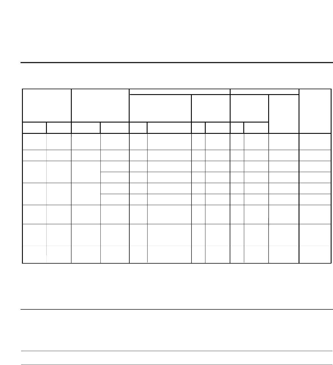
206-4118 PAGE 39
OLD_OCV
=0
OLD_OCV=
1Source Input Source Mode Number Labeling Value Labeling Value Labeling
130 90 Video2 (Side) CV/SVIDEO 34 CAMPORT_EN 0x01 Video Front
(Camport) 0Video Front
(Camport) 0 (VIDE0) 2
131 91 Video1 (Rear) CV/SVIDEO 39 REAR_AUX_EN 0x02 Rear Video
(Aux) 1Rear Video
(Aux) 0 (VIDE0) 1
DTV 91 YPrPb2 EN = 1 0x04 S-Video
Rear 2S-Video
Rear 0 (VIDE0) 5
PC 91 YPrPb2 EN = 2 0x04 S-Video
Rear 2S-Video
Rear
2
(COMPUTER) 5
DTV 35 COMPPORT EN = 1 0x08 Front
Computer 3Front
Computer 0 (VIDE0) 3
PC 35 COMPPORT EN = 2 0x08 Front
Computer 3Front
Computer
2
(COMPUTER) 3
PC 87 REAR RGB EN = 2 0x10 SVGA Rear
Computer 4SVGA Rear
Computer
2
(COMPUTER) 4
136 96 Component 38 YPrPb EN 0x40 Y/UV
Component 6
Rear
Y/PrPb
Componen
t
video
0 (VIDE0) 6
Installer Menu
TV
DIRECT ACCESS
Tuning START AUX
SOURCE
ASSIGNMENT
DATA
STATUS
TYPE 0X0D
AUX SOURCE
(R)
ENABLE MPI DATA
DATA STATUS
TYPE 0xD2
CURRENT AV
SOURCE (R)
MPI DATA
STATUS TYPE
0x41 SOURCES
ENABLED (R/W)
132 92 HDMI2
134 94 RGB
133 93 HDMI1/DVI
137 97 USB 121 USB Options 0x80 Y/C Front
Video
6Front
S-Video
2 (Comp) NA
TV Aux Input Configuration / Troubleshooting
Troubleshooting
Some quick and easy tips to resolving problems
Symptoms Possible Cause(s) Possible Solution(s)
Software Problems
Cannot direct enter Channel not included in channel After 2-5-5 + MENU, only channels included in TV controller will appear.
channel number or scan in TV controller. If channel is available it can be added to channel scan. If it is not
“No Signal” appears. available, the ‘No Signal’ message appears on the TV screen.

PAGE 40 206-4118
Some quick and easy tips to resolving problems
Symptoms Possible Cause(s) Possible Solution(s)
Power
No Power. See troubleshooting flow chart.
Display Panel Picture
No Picture. • Display panel is turned off. -Turn TV on.
-Power failure?
• Antenna/Cable not connected. -Connect Antenna/Cable signal to TV. (See Owners manual)
• Connections incorrect. -Check connections on TV. (See Owners manual)
• M.P.I. not connected. -If applicable, connect M.P.I. cable to M.P.I. device.
• Encrypted program. -Try another channel.
• Wrong tuning band. -Adjust Installer menu settings.
Erratic Operation
Installer menu setup. • Wrong Installer menu settings. -Adjust Installer menu settings as required.
Remote Control
Remote doesn’t work. • Remote not in TV mode. -Use Mode key to select TV; puts remote into TV mode.
• Not aimed at IR remote sensor. -Point remote at TV’s IR receiver on TV.
• Remote too far from IR sensor. -Move remote closer to TV’s IR receiver or darken room.
• IR path to TV’s receiver obstructed. -Remove obstructions.
• Weak batteries. -Replace batteries.
• Wrong battery polarity. -Check that “+” and “-” match in battery compartment.
• Too much light in room. -Dim room light.
• Wrong Installer remote control. -Requires compatible Installer remote, contact your LG dealer.
Picture Reception
Normal picture, poor • Audio muted. -Press MUTE or use Volume Up key to increase sound level.
or no sound. • Broadcast problem. -Try a different channel.
Note: For other problems not caused by the TV, refer to other devices’ operating guide.
Troubleshooting

PAGE 41
206-4118
Reset Clone After Static Shock
After replacing exhausted batteries, or if the programmer
behaves strangely after a static shock, use a paper clip or simi-
lar instrument inserted through the small hole marked ”RESET”
to activate the internal reset switch and restore normal opera-
tion. After a reset, check the real-time clock setting. It may be
necessary to reset the Clone Programmer clock from a TV con-
taining the correct time.
Note
The LT2002 programmer is designed to be used with TVs con-
taining the 221-01006 and later processors. Use with earlier TV
sets may give unpredictable results. Processors used before the
221-01006-04 have a limited screen display capability. They
cannot display entire screens as shown in the quick setup
instructions accompanying the LT2002 clone programmer. Use
the printed menu illustrations on the quick setup sheet sup-
plied with the Clone as an aid to making your programming
choices. (Although the menus are not all displayed, the clone
functions all operate normally.)
• After cloning operations are complete, just unplug the LT2002 from the TV.
• If the TV does not display a picture on the TV (blank screen) after a few seconds, just change channels.
Clone Programmer Troubleshooting
Problem Possible Cause(s) Possible Solution(s)
Clone Programmer
Clone copies Setup in • Not enough time to copy - Press Reset on clone programmer, redo teach/learn.
less than 30 seconds entire TV setup. (Teach/Learn should take a minimum of 1 minute.)
Remote does not • Wrong Installer remote. - Only use an LG Installer remote to operate clone programmer
operate clone. with TV.
LED does not blink. • M.P.I. cord not connected. - Connect M.P.I. cord properly, assure good connection.
• TV not turned on. - TV must be powered On for clone to work.
• Weak batteries. - Install 4 fresh AA high-quality alkaline batteries.
Clone menu hard • Weak signal. - Connect TV to a reliable Analog channel signal
to read. source.
No time set. • Time not available. - Set time on a TV, copy time to Clone Programmer.
Clone not working. • Clone programmer - Try a different LT2002 Clone programmer.
problem. - Reset Clone Programmer.
Clone Scans Channels • Clone should only scan - Retry cloning again.
more than once. channels once.
Master and Other TVs
Cloning did not work. • Procedure interrupted. - Wait until procedure complete message is displayed.
• Different TV models. - Cloning is only possible with identical model TVs.
• Step(s) omitted or - Reread pages 7-8-9 to be sure all tasks were performed.
not performed.
Clone time disappeared. • Batteries were removed. - Batteries must remain installed to retain time settings.
New Setup not present. • TV not reset. - Disconnect newly-cloned unit from power for 5 seconds.
Reference: LT2002 Cloning Procedure Troubleshooting
Warning: Do not use LT2002 while any PPV card is
installed in TV or clone programmer will be damaged.
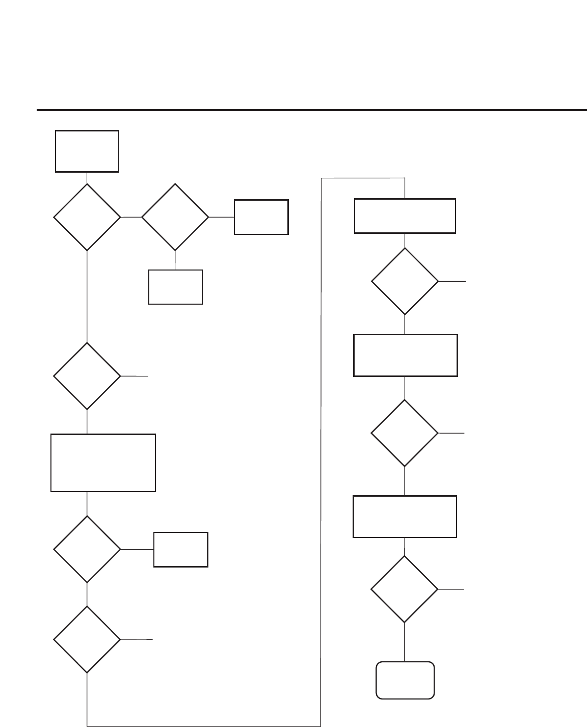
PAGE 42 206-4118
Controller
Quick
Check
Is
'STATUS'
LED on
Analog Board
Blinking
?
Plug
into AC
Power Outlet
Is
TV
Connected to
AC Power
?
Bad
TV
Yes
No No
Yes
Is
Red LED
on TV
Lit
?
1. Bad Analog Board.
2. Bad Digital Board.
No
Cycle the power by removing
and re-connecting the AC
power cord. Observe the
'POWER' LED and TV screen
as soon as AC power is
re-applied.
Bad
TV
Did
Analog
Board 'POWER'
LED Turn On
Momentarily
?
No
Check to see if TV
is in Commercial Mode.
See Commercial Mode
Check chart.
Did TV
Turn On
Momentarily
?
No
Yes
Yes
Yes
Did
TV Turn
On
?
Yes
No
Press 'POWER' or 'ON/OFF'
key on TV
1. Bad TV
Press 'POWER' or 'ON/OFF'
or 'VOLUME UP/DOWN' or
'MUTE' key on Installer
Remote
Did
TV
Respond
?
No 1. Bad TV
2. Go to Remote
Control Checklist page 5
Yes
Press 'POWER' or 'ON/OFF'
or 'VOLUME UP/DOWN'
or 'MUTE' key on
User-Supplied Remote
Did
TV
Respond
?
No 1. Bad PPV Card
2. Go to Remote
Control Checklist page 5
Yes
End
Troubleshooting Flow Chart
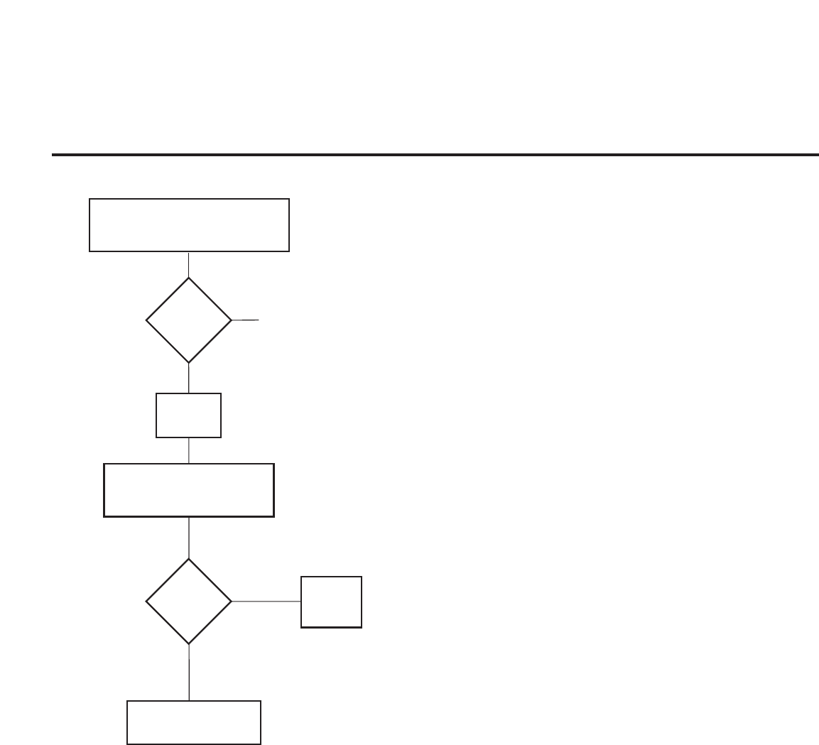
PAGE 43
206-4118
Commercial Mode Check
Press the "On/Off" key
on the front panel.
The On/Off key is always operational.
Did
you get
a response
?
Bad TV
Yes
No
Did
TV stop
responding
or continue
to respond
?
TV is in
Commercial
Mode.
Stopped
responding
TV is not in Commercial Mode
Call Technical Support for
Assistance
Continued
to
respond
Leave
the
TV set On
Go to Installer menu
by pressing "MENU" until
the TV stops responding.

206-4118
75 OHM RF CABLE
The wire that comes from an off-air antenna
or cable service provider. The end looks like
a hex-shaped nut with a wire sticking
through the middle. It screws onto the
Antenna/Cable threaded jack on the back of
the TV.
300 TO 75 OHM ADAPTER
A small device that connects a two-
wire 300 ohm antenna to a 75 ohm RF jack.
They are usually about an inch long with two
screws on one end and a round opening with
a wire sticking out on the other end.
A/V CABLES
Audio/Video cables. Three cables bunched
together—right audio (red), left audio
(white), and video (yellow). A/V cables are
used for stereo playback of videocassettes
and for higher quality picture and sound
from other A/V devices.
A/V DEVICE
Any device that produces video or sound
(VCR, DVD, cable box, or television).
AMPLIFIER
An electronic device that amplifies sound
from a television, CD player, VCR, DVD, or
other Audio/Video device.
ANTENNA
The physical receiver of television signals
sent over the air. A large metal piece of
equipment does not always have to be visible
to be using an antenna.
B-LAN
TV is controlled by external network.
CABLE
Cable service box. Refers to the descrambler
box cable subscribers use to receive cable
programming signals.
CATV
Programming provided by a cable service.
DIGITAL TELEVISION
High-resolution, cinema-quality television
signals transmitted digitally.
DVI
Digital Video Interface
Accommodates analog and digital interfaces
with a single connector.
COMPOSITE VIDEO
Typical video jack, uses one wire for trans-
porting three-color video signals.
COMPONENT VIDEO
Uses three wires for transporting three-color
video signals. The end result is usually better
video quality.
DELETED
Lets you remove channels from the list that
the end user can scroll through using CH
(Channel) Up/Down.
HDMI
High-definition multi-media interface.
HDTV
High-definition television. Refers to televi-
sion signals that have higher resolution than
ordinary analog TV signals.
HDSTB
High-definition set top box. Refers to a
tuner device that receives high-definition
television signals which have higher resolu-
tion than ordinary analog TV signals.
INPUT
Refers to the input jack that receives a sig-
nal from a TV, VCR, DVD Player or other
Audio/Video device.
JACK
An input or output connector on the back
of a TV, VCR, DVD Player or other
Audio/Video device.
MONO SOUND
Mono (monaural) sound is one channel of
sound. On more than one speaker, all the
speakers play the same audio.
OUTPUT
Refers to the output jack that sends a signal
out of a VCR, DVD, or other A/V device.
PHYSICAL CHANNEL NUMBER
The actual channel number. Analog channels
use the physical channel number and digital
channels can use a virtual channel number.
RGB (Red, Green, Blue)
Connection input or output port available for
producing a video image using three sepa-
rate colors: Red, Green, and Blue.
RS-232
Serial communication port through which
firmware is downloaded.
2ND AUDIO PROGRAMMING/SAP
Second Audio Programming (SAP) is another,
separate audio channel available with some
programming. Choosing SAP often refers to
listening to audio in another language, such
as Spanish or French.
SIGNAL
Picture and sound traveling through a cable,
or over the air, to the TV.
STEREO SOUND
Stereo (Stereophonic) sound refers to audio
that’s divided into right and left sides.
TUNER
Device that picks up the broadcast signal
and turns it into picture and sound.
VIRTUAL CHANNEL NUMBER
A re-mapped channel number analog chan-
nels use the actual channel number. but dig-
ital channels use a virtual(or false) channel
number.
XDS
Extended Data Service: Additional program
information included on the signal provided
at the discretion of the broadcaster.
Note 1
Refer to www.atsc.org for further informa-
tion.
Glossary of Terms
A list of definitions for some of the words found in this guide
PAGE 44

PAGE 45
206-4118
B-LAN Overview
B-LAN Setup and Overview (Except 32LH240H)
Power to the B-LAN module is controlled by Installer Menu Item 118 Power savings. By default, value 003, the B-LAN module is
only powered on when the TV is powered on. There are two bits in the Power Savings item to control power to the B-LAN module,
one for power during TV Standby mode and one for power during TV Power On mode. When the bit is 0, the B-LAN module is pow-
ered. When the bit is 1, the B-LAN module is not powered (Power Savings is Enabled).
The B-LAN module is internal to the TV. It allows the Hotel/Institution headend equipment to communicate with the TV for config-
uration and control. This communication is via the institution’r RF distribution system. The control device at the headend (ex FMA-
LG101) can control multiple TVs. When the TV is first installed, it must be powered on in order for the headend to be able to com-
municate with the B-LAN. At this point, if it is desired for the BLAN to always be powered on, particularly during Standby mode,
the BLAN Standby Power Saving mode setting should be downloaded as Disabled. The new settings will not be active until the
BLAN actually downloads the configuration data to the PTC and the PTC is reset.
If it known that the application requires only using the MPI card slot and not the embedded BLAN, the installer can go into the
Installer Settings menu and enable the BLAN Power Savings mode, in both Standby and TV power on.
Power Saving
1
3
7
TV Power On State
Standby
Standby
Standby
TV Standby State
On
Off
Off
BLAN Power MPI Slot Power BLAN Power MPI Slot Power
On
On
Off
Main
Main
Main

Reference: RJP Model List and Input Hierarchy
RJP Model List
Legacy Models Scaler Models
RJP-101M Not Support PCB
RJP-101ML Not Support PCB
RJP-110F RJP-210F
RJP-110FW RJP-210FW
RJP-110W RJP-210W
RJP-110WBR RJP-210WBR
RJP-110S RJP-210S
RJP-120G RJP-220G
RJP-120T RJP-220T
RJP-201B RJP-301B
RJP-202B RJP-302B
RJP Input Hierarchy
Priority Video Audio
1st. (Highest) HDMI / DVI 3.5mm Mini Jack
2nd. RGB L / R Audio In
3rd. Composite HDMI / DVI
4th. (Lowest) TV (RF or Aux) TV (RF or Aux)
206-4118
PAGE 46

Regulatory Information cont.
FCC Compliance Statement
This equipment has been tested and found to comply
within the limits of a Class B digital device pursuant to Part
15 of the FCC Rules. These limits are designed to provide
reasonable protection against harmful interference in a
residential installation.
This equipment generates, uses, and can radiate radio
frequency energy and if not installed and used in
accordance with the instructions, may cause harmful
interference to radio communications. However, there is
no guarantee that interference will not occur in a particular
installation.
If this equipment does cause harmful interference to radio
or television reception (which can be determined by
turning the equipment on and off), the user is encouraged
to try to correct the interference by using one or more of
the following measures:
Reorient or relocate the receiving antenna.
Increase the separation between the equipment and
the receiver.
Connect the equipment into an outlet on a circuit
different from that to which the receiver is connected.
Consult the dealer or an experienced radio/TV
technician for help.
Caution: Changes or modifications not expressly approved
by the party responsible for compliance could void the
user's (or your) authority to operate the equipment. Only
peripherals (digital input/output devices, terminals, printers,
etc.) certified to comply with the Class B limits may be
attached to this monitor. Operation with non-certified
peripherals is likely to result in interference to radio and TV
reception. Only shielded signal cables may be used with
this System.
Canadian DOC Notice
This Class B digital apparatus meets all requirements of
the Canadian Interference-Causing Equipment
Regulations. Cet appareil numérique de la classe B
respecte toutes les exigences du Règlement sur le
matériel brouilleur du Canada.
CE Conformity Notice
(for Europe)
Products with the “CE” Marking comply with the EMC
Directive(89/336/EEC) and LOW VOLTAGE Directive
(73/23/EEC) issued by the Commission of the European
Community.
Compiance with these directives implies conformity to the
following European Norms :
• EN 55022 ; Radio Frequency Interference
• EN 55024 ; Electromagnetic Immunity
• EN 61000-3-2 ; Power Line Harmonics
• EN 61000-3-3 ; Voltage Fluctuations
• EN 60950-1 ; Product Safety
Low Radiation Compliance (MPR II)
This monitor meets one of the strictest guidelines available
today for low radiation emissions, offering the user extra
shielding and an antistatic screen coating. These
guidelines, set forth by a government agency in Sweden,
limit the amount of emission allowed in the Extremely Low
Frequency (ELF) and Very Low Frequency (VLF)
electromagnetic range.
01
NOTICE
The regulations are applied only to the products with the
ID LABEL indicating specific requirements.
NOTICE
The regulations are applied only to the products with the
ID LABEL indicating specific requirements.
NOTICE
The regulations are applied only to the products with the
ID LABEL indicating specific requirements.
TCO'99 (TCO'99 applied model only)
Congratulations!
You have just purchased a TCO’99 approved and labelled
product! Your choice has provided you with a product
developed for professional use. Your purchase has also
contributed to reducing the burden on the environment and
also to the further development of environmentally
adapted electronics products.

Regulatory Information cont.
02
Why do we have environmentally labelled computers?
In many countries, environmental labelling has become an
established method for encouraging the adaptation of
goods and services to the environment. With the growing
manufacture and usage of electronic equipment
throughout the world, there is a recognized concern for the
materials and substances used by electronic products
with regards to their eventual recycling and disposal. By
proper selection of these materials and substances, the
impact on the environment can be minimized.
There are also other characteristics of a computer, such as
energy consumption levels, that are important from the
viewpoints of both the work (internal) and natural (external)
environments. Electronic equipment in offices is often left
running continuously, resulting in unnecessary
consumption of large amounts of energy and additional
power generation. From the standpoint of carbon dioxide
emissions alone, it is vital to save energy.
What does labelling involve?
The product meets the requirements for the TCO’99
scheme which provides for international and environmental
labelling of personal computers and/or displays.
The labelling scheme was developed as a joint effort by the
TCO (The Swedish Confederation of Professional
Employees), Svenska Naturskyddsforeningen
(The Swedish Society for Nature Conservation) and
Statens Energimyndighet (The Swedish National
Energy Administration).
Approval requirements cover a wide range of issues:
ecology, ergonomics, emission of electrical and magnetical
fields, energy consumption and electrical safety.
Ecological criteria impose restrictions on the presence and
use of heavy metals, brominated and chlorinated flame
retardants, and other substances. The product must be
prepared for recycling and the manufacturing site(s) shall
be certified according to ISO14001 or EMAS registered.
Energy requirements include a demand that the system
unit and/or display, after a certain period of inactivity,
shall reduce its power consumption to a lower level in one
or more stages. The length of time to reactivate the system
unit shall be reasonable for the user.
Labelled products must meet strict environmental
demands, for example, in respect of the reduction of
electrical and magnetical fields as well as work load and
visual ergonomics.
Below you will find a brief summary of the ecological
requirements met by this product. The complete
ecological criteria document can be found at TCO
Development’s website http://www.tcodevelopment.com
or may be ordered from:
TCO Development
SE-114 94 STOCKHOLM, Sweden
Fax: +46 8 782 92 07
Email : development@tco.se
Information regarding TCO’99 approved and labelled
products may also be obtained at
http://www.tcodevelopment.com
Ecological requirements
Flame retardants
Flame retardants may be present in printed wiring board
laminates, cables, and housings. Their purpose is to
prevent, or at least to delay the spread of fire. Up to 30%
by weight of the plastic in a computer casing can consist of
flame retardant substances. Many flame retardants
contain bromine or chlorine, and these flame retardants
are chemically related to PCBs (polychlorinated
biphenyls). Both the flame retardants containing bromine
or chlorine and the PCBs are suspected of giving rise to
health effects, including reproductive damage in fish-
eating birds and mammals, due to the bio-accumulative*
processes when not disposed of in accordance with strict
standards for disposal.
TCO’99 requires that plastic components weighing more
than 25 grams shall not contain flame retardants with
organically bound bromine or chlorine. Flame retardants
are allowed in the printed wiring board laminates due to
the lack of commercially available alternatives.
Cadmium**
Cadmium is present in rechargeable batteries and in the
colour-generating layers of certain computer displays.
TCO’99 requires that batteries, the colour-generating
layers of display screens, and the electrical or electronics
components shall not contain any cadmium.
Mercury**
Mercury is sometimes found in batteries, relays and
switches. TCO’99 requires that batteries shall not contain
any mercury. It also demands that mercury is not present
in any of the electrical or electronics components
associated with the labelled unit. There is however one

Regulatory Information cont.
03
exception. Mercury is, for the time being, permitted in the
back light system of flat panel monitors as there today is
no commercially available alternative. TCO aims on
removing this exception when a mercury free alternative is
available.
Lead**
Lead can be found in picture tubes, display screens,
solders and capacitors. TCO’99 permits the use of lead
due to the lack of commercially available alternatives, but
in future requirements TCO Development aims at
restricting the use of lead.
_____________________________________________
* Bio-accumulative is defined as substances which
accumulate in living organisms.
**Lead, Cadmium and Mercury are heavy metals
which are bio-accumulative.
TCO’03
(TCO’03 applied model only)
Congratulations!
The display you have just purchased carries the TCO’03
Displays label.
This means that your display is designed,manufactured
and tested according to some of the strictest quality and
environmental requirements in the world. This makes for a
high performance product, designed with the user in focus
that also minimizes the impact on our natural environment.
Some of the features of the TCO’03 Display requirements:
Ergonomics
• Good visual ergonomics and image quality in order to
improve the working environment for the user and to
reduce sight and strain problems. Important
parameters are luminance, contrast, resolution,
reflectance, colour rendition and image stability.
Energy
• Energy-saving mode after a certain time – beneficial
both for the user and the environment
• Electrical safety
Emissions
• Electromagnetic fields
• Noise emissions
Ecology
• The product must be prepared for recycling and the
manufacturer must have a certified environmental
management system such as EMAS or ISO 14 001
• Restrictions on
chlorinated and brominated flame retardants and
polymers
heavy metals such as cadmium, mercury and lead.
The requirements included in this label have been
developed by TCO Development in co-operation with
scientists, experts, users as well as manufacturers all over
the world. Since the end of the 1980s TCO has been
involved in influencing the development of IT equipment in
a more user-friendly direction. Our labelling system started
with displays in 1992 and is now requested by users and
IT-manufacturers all over the world.
For more information, please visit
www.tcodevelopment.com
Information for Environmental Preservation
LGE. announced the 'LG Declaration for a Cleaner
Environment' in 1994, and this ideal has served as a
guiding managerial principle ever since. The Declaration is
a foundation that has allowed us to undertake
environmentally friendly activities in careful consideration
of economic, environmental, and social aspects.
We promote activities for environmental preservation, and
we specifically develop our products to embrace the
concept of environment-friendly.
We minimize the hazardous materials contained in our
products. For example, there is no cadmium to be found in
our monitors.
Information for recycling
This monitor may contain parts which could be hazardous
to the environment. It is important that this monitor be
recycled after use.
LGE. handles all waste monitors through an
environmentally acceptable recycling method. There are
several take-back and recycling systems currently in
English

Regulatory Information cont.
04
operation worldwide. Many parts will be reused and
recycled, while harmful substances and heavy metals are
treated by an environmentally friendly method.
If you want to find out more information about our
recycling program, please contact your local LG vendor or
a corporate representative of LG.
We set our vision and policies on a cleaner world by
selecting the issue of the global environment as a task for
corporate improvement. Please visit our website for more
information about our ‘green’ policies.
http://www.lge.com/about/environment/html/Recycling.jsp
Informationen zur Erhaltung der Umwelt
Im Jahr 1994 verkündete LGE die 'LG Declaration for a
Cleaner Environment' (LG Erklärung für eine sauberere
Umwelt). Seitdem dient dieses Ideal als führendes Prinzip
des Unternehmens. Diese Erklärung war die Basis für die
Durchführung von
umweltfreundlichen Aktivitäten, wobei wirtschaftliche,
umweltbezogene und soziale Aspekte in die
Überlegungen mit einbezogen wurden.
Wir fördern Aktivitäten zum Schutz der Umwelt und die
Entwicklung unserer Produkte ist darauf ausgerichtet,
unserem Konzept bezüglich Umweltfreundlichkeit gerecht
zu werden.
Wir sind darauf bedacht, den Anteil der in unseren
Produkten enthaltenen schädlichen Materialien zu
minimieren. So ist in unseren Monitoren beispielsweise
kein Kadmium zu finden.
Informationen zum Thema Recycling
Dieser Monitor enthält Teile, die umweltschädlich sein
können. Es ist unbedingt erforderlich, dass der Monitor
recycelt wird, nachdem er außer Dienst gestellt wurde.
Bei LGE. werden alle ausrangierten Monitore in einem
unter umweltbezogenen Aspekten geeigneten Verfahren
recycelt. Augenblicklich sind weltweit mehrere
Rücknahme- und Recyclingsysteme im Einsatz. Viele
Teile werden wieder verwendet und recycelt. Schädliche
Substanzen und Schwermetalle werden durch
umweltverträgliche Verfahren behandelt.
Falls Sie mehr über unser Recyclingprogramm erfahren
möchten, wenden Sie sich bitte an Ihren lokalen LG-
Händler oder einen Unternehmensvertreter von LG.
Wir richten unsere Firmenpolitik auf eine sauberere
Umwelt hin aus, indem wir umweltspezifische Aspekte als
wichtigen Punkt in die Weiterentwicklung unseres
Unternehmens einfließen lassen. Zusätzliche
Informationen über unsere ‘grüne’ Firmenpolitik erhalten
Sie auf unserer Website.
http://www.lge.com/about/environment/html/Recycling.jsp
Information sur la protection del’environnement
LGE. a publié sa 'Déclaration en faveur d’un
environnement plus propre' en 1994 et celle-ci est restée,
depuis lors, un principe directeur de notre entreprise.
Cette déclaration a servi de base à notre réflexion et nous
a permis de prendre en compte à la fois les aspects
économiques et sociaux de nos activités, tout en
respectant l’environnement.
Nous encourageons les activités en faveur de la
préservation de l’environnement et c’est dans cet esprit
que nous développons nos produits : nous réduisons au
minimum les matières dangereuses qui entrent dans leur
composition et l’on ne trouve pas de cadmium, par
exemple, dans nos moniteurs.
Information sur le recyclage
Ce moniteur peut contenir des composants qui présentent
un risque pour l’environnement. Il est donc important que
celui-ci soit recyclé après usage.
LGE. traite les moniteurs en fin de cycle conformément à
une méthode de recyclage respectueuse de
l’environnement. Nous reprenons nos produits et les
recyclons dans plusieurs sites répartis dans le monde
entier. De nombreux composants sont réutilisés et
recyclés, et les matières dangereuses, ainsi que les
métaux lourds, sont traités selon un procédé écologique.
Si vous souhaitez plus de renseignements sur notre
programme de recyclage, veuillez contacter votre
revendeur LG ou un l’un de nos représentants.
Nous voulons agir pour un monde plus propre et croyons
au rôle de notre entreprise dans l’amélioration de
l’environnement. Pour plus de renseignements sur notre
politique “verte”, rendez visite à notre site :
http://www.lge.com/about/environment/html/Recycling.jsp
Deutsch
Français

05
Regulatory Information cont.
Informazioni per la tutela dell’ambiente
La LGE. ha annunciato nel 1994 la cosiddetta 'LG
Declaration for a Cleaner Environment' (Dichiarazione di
LG a favore di un ambiente più pulito), un ideale che da
allora funge da principio ispiratore della gestione
aziendale. La dichiarazione rappresenta il fondamento che
consente di intraprendere attività a favore dell'ambiente
tenendo conto degli aspetti economici, ambientali e
sociali.Noi della LG, promuoviamo attività a favore della
tutela dell'ambiente sviluppando appositamente i nostri
prodotti per cogliere il concetto del rispetto dell’ambiente
riducendo i materiali dannosi presenti nei nostri prodotti.
Ad esempio nei nostri monitor non è presente il cadmio.
Informazioni per il riciclaggio
Il monitor può presentare componenti che potrebbero
risultare eventualmente dannosi per l'ambiente. È
importante che il monitor sia riciclato al termine del suo
utilizzo.
La LGE. gestisce tutti i monitor di rifiuto con un metodo di
riciclaggio soddisfacente dal punto di vista ambientale. In
tutto il mondo sono attualmente in funzione numerosi
sistemi di riciclaggio e recupero. I diversi componenti sono
riutilizzati e riciclati, mentre le sostanze dannose e i metalli
pesanti vengono trattati con un metodo rispettoso
dell’ambiente.
Se si desiderano maggiori informazioni in merito al
programma di riciclaggio, è consigliabile rivolgersi al
proprio rivenditore LG o ad un rappresentante aziendale
della LG.
Noi della LG impostiamo la nostra visione e le nostre
politiche a favore di un mondo più pulito ponendo la
questione dell'ambiente dal punto di vista globale come
una mansione rivolta al miglioramento della nostra
azienda. Vi invitiamo a visitare il nostro sito internet per
ulteriori informazioni sulla nostra politica “verde”.
http://www.lge.com/about/environment/html/Recycling.jsp
Información para la conservación
medioambiental
LGE. presentó la 'Declaración para un entorno más limpio
de LG' en 1994 y este ideal ha servido para guiar nuestros
principios empresariales desde entonces. La Declaración
es la base que nos ha permitido llevar a cabo tareas que
respetan el medio ambiente siempre teniendo en cuenta
aspectos sociales,
económicos y medioambientales.
Promocionamos actividades orientadas a la conservación
del medio ambiente y desarrollamos nuestros productos
específicamente para que se ajusten a la filosofía que
protege el entorno.
Reducimos al máximo el uso de materiales de riesgo en
nuestros productos. Un ejemplo de ello es la ausencia
total de cadmio en nuestros monitores.
Información para el reciclaje
Este monitor puede contener piezas que entrañen riesgos
medioambientales. Es importante reciclar este monitor
después de su utilización.
LGE. trata todos los monitores usados siguiendo un
método de reciclaje que no daña al entorno. Contamos
con diversos sistemas de recuperación y reciclaje que
funcionan a nivel mundial en la actualidad. Es posible
reciclar y reutilizar muchas de las piezas, mientras que las
sustancias dañinas y los metales pesados se tratan
siguiendo un método que no perjudique al medio
ambiente. Si desea obtener más información acerca del
programa de reciclaje, póngase en contacto con su
proveedor local de LG o con un representante empresarial
de nuestra marca.
Basamos nuestra visión y nuestras políticas en un mundo
más limpio y para ellos optamos por un entorno global
como tarea principal de nuestra evolución como empresa.
Visite nuestra página Web para obtener más información
sobre nuestras políticas ecológicas.
http://www.lge.com/about/environment/html/Recycling.jsp
Informações relacionadas à preservação
ambiental
A LGE. anunciou a 'LG Declaration for a Cleaner
Environment' (Declaração da LG para um ambiente mais
limpo) em 1994 e esse ideal tem servido desde então
como um princípio administrativo de orientação. A
Declaração é a base que nos tem permitido realizar
atividades favoráveis ao ambiente com consideração
atenta aos aspectos econômicos, ambientais e sociais.
Promovemos atividades de preservação ambiental e
desenvolvemos nossos produtos para englobar
Italiano
Espanõl
Português

06
Regulatory Information cont.
especificamente o conceito de favorável ao ambiente.
Reduzimos os materiais perigosos contidos em nossos
produtos. Por exemplo, não há cádmio em nossos
monitores.
Informações relacionadas à reciclagem
Este monitor pode conter peças que podem representar
riscos ao ambiente. É importante que ele seja reciclado
após o uso.
A LGE. cuida de todos os monitores descartados através
de um método de reciclagem agradável ao ambiente. Há
vários sistemas de devolução e reciclagem atualmente
em operação no mundo. Muitas peças serão reutilizadas
e recicladas e as substâncias nocivas e os metais
pesados passarão por tratamento através de um método
favorável ao ambiente.
Para obter mais informações sobre nosso programa de
reciclagem, entre em contato com seu fornecedor LG
local ou com um representante corporativo da LG.
Definimos nossa visão e nossas políticas relacionadas a
um mundo mais limpo selecionando a questão do
ambiente global como uma tarefa de aprimoramento
corporativo. Visite nosso site para obter mais informações
sobre nossas políticas de meio ambiente.
http://www.lge.com/about/environment/html/Recycling.jsp
Informatie met betrekking tot het behoud van
het milieu
LGE. publiceerde in 1994 de 'LG Declaration for a Cleaner
Environment' (de LG-verklaring met betrekking tot een
schoner milieu). Deze verklaring en het ideaal van een
schoner milieu fungeren sindsdien als een bestuurlijke
leidraad voor onze onderneming. Op basis van deze
verklaring ontplooien wij milieuvriendelijke activiteiten,
waarbij er zowel met sociale en economische aspecten,
als met milieuaspecten zorgvuldig rekening wordt
gehouden.
Wij ondersteunen activiteiten die zijn gericht op het
behoud van het milieu en wij houden bij het ontwikkelen
onze producten specifiek rekening met de
milieuvriendelijkheid van onze producten.
Wij minimaliseren het gebruik van schadelijke stoffen in
onze producten. Er wordt bijvoorbeeld geen cadmium
verwerkt in onze monitors.
Nederlands
Informatie met betrekking tot recycling
Deze monitor bevat materialen die schadelijk zouden
kunnen zijn voor het milieu. Het is belangrijk dat deze
monitor aan het einde van zijn levensduur wordt
gerecycled.
LGE. verwerkt alle afvalmonitors via een milieuvriendelijke
recyclingmethode. Hiervoor worden er momenteel
wereldwijd verscheidene inname- en recyclingsystemen
gehanteerd. Een groot aantal onderdelen wordt opnieuw
gebruikt en gerecycled, waarbij schadelijke stoffen en
zware metalen volgens een milieuvriendelijke methode
worden verwerkt.
Voor meer informatie over ons recyclingprogramma kunt u
contact opnemen met uw plaatselijke LG-
vertegenwoordiger of een LG-vestiging.
Onze visie en ons beleid met betrekking tot een schonere
wereld vloeien voort uit het feit dat wij het milieu hebben
aangemerkt als een onderwerp dat speciale aandacht
verdient binnen onze onderneming. Bezoek onze website
voor meer informatie over ons 'groene' beleid.
http://www.lge.com/about/environment/html/Recycling.jsp
»ÌÙÓχˆËˇ ÔÓ Óı‡Ì ÓÍÛʇ˛˘ÂÈ Ò‰˚
¬ 1994 „Ó‰Û ÍÓÔÓ‡ˆËˇ LGE ÓÔÛ·ÎËÍÓ‚‡Î‡
'ƒÂÍ·‡ˆË˛ LG ÔÓ Óı‡Ì ÓÍÛʇ˛˘ÂÈ Ò‰˚',
ÍÓÚÓ‡ˇ Ò ÚÂı ÔÓ ÒÎÛÊËÚ ÓÒÌÓ‚Ì˚Ï ÔË̈ËÔÓÏ
ÛÔ‡‚ÎÂÌˡ. Õ‡ ÓÒÌÓ‚Â ˝ÚÓÈ ‰ÂÍ·‡ˆËË Ï˚ ÒÏÓ„ÎË
Ô‰ÔËÌˇÚ¸ ‰ÂÈÒڂˡ, Ó·ÂÒÔ˜˂‡˛˘ËÂ
·ÂÁÓÔ‡ÒÌÓÒÚ¸ ÓÍÛʇ˛˘ÂÈ Ò‰˚, Û‰ÂΡˇ ÔË ˝ÚÓÏ
‰ÓÎÊÌÓ ‚ÌËχÌË ˝ÍÓÌÓÏ˘ÂÒÍËÏ, ˝ÍÓÎӄ˘ÂÒÍËÏ Ë
ÒӈˇθÌ˚Ï ‡ÒÔÂÍÚ‡Ï.
Ã˚ ÒÚËÏÛÎËÛÂÏ ‰ÂˇÚÂθÌÓÒÚ¸ ÔÓ Óı‡ÌÂ
ÓÍÛʇ˛˘ÂÈ Ò‰˚, Û‰ÂΡˇ ÓÒÓ·Ó ‚ÌËχÌËÂ
‡Á‡·ÓÚÍ ̇¯ÂÈ ÔÓ‰Û͈ËË ‚ ÒÓÓÚ‚ÂÚÒÚ‚ËË Ò
ÍÓ̈ÂÔˆËÂÈ ˝ÍÓÎӄ˘ÂÒÍÓÈ ·ÂÁÓÔ‡ÒÌÓÒÚË.
Ã˚ Ò‚Ó‰ËÏ Í ÏËÌËÏÛÏÛ ÒÓ‰ÂʇÌË ÓÔ‡ÒÌ˚ı
‚¢ÂÒÚ‚ ‚ ̇¯ÂÈ ÔÓ‰Û͈ËË. Õ‡ÔËÏÂ, ‚ ̇¯Ëı
ÏÓÌËÚÓ‡ı ‚˚ Ì ̇ȉÂÚ ͇‰Ïˡ.
»ÌÙÓχˆËˇ ÔÓ ÛÚËÎËÁ‡ˆËË ÓÚıÓ‰Ó‚
›ÚÓÚ ÏÓÌËÚÓ ÏÓÊÂÚ ÒÓ‰Âʇڸ ÍÓÏÔÓÌÂÌÚ˚,
ÍÓÚÓ˚ ÏÓ„ÛÚ Ì‡ÌÂÒÚË Û˘Â· ÓÍÛʇ˛˘ÂÈ Ò‰Â.
Russian
07
Regulatory Information cont.
EPA
(EPA applied model only)
ENERGY STAR
is a set of power-saving guidelines
issued by the U.S. Environmental Protection
Agency(EPA).
NOM MARK (Mexico only)
ÕÂÓ·ıÓ‰ËÏÓ ÛÚËÎËÁËÓ‚‡Ú¸ ÏÓÌËÚÓ ÔÓÒÎÂ
ËÒÔÓθÁÓ‚‡Ìˡ.
KÓÔÓ‡ˆËˇ LGE Ô‡·‡Ú˚‚‡ÂÚ ‚Ò ·‡ÍÓ‚‡ÌÌ˚Â
ÏÓÌËÚÓ˚ Ò ÔÓÏÓ˘¸˛ ˝ÍÓÎӄ˘ÂÒÍË ÔËÂÏÎÂÏÓ„Ó
ÏÂÚÓ‰‡ ÛÚËÎËÁ‡ˆËË ÓÚıÓ‰Ó‚. œÓ ‚ÒÂÏÛ ÏËÛ
‰ÂÈÒÚ‚Û˛Ú ÒËÒÚÂÏ˚ ÛÚËÎËÁ‡ˆËË ÓÚıÓ‰Ó‚ Ë ‚ÓÁ‚‡Ú‡
ËÒÔÓθÁÓ‚‡ÌÌÓÈ ÔÓ‰Û͈ËË. ÃÌÓ„Ë ÍÓÏÔÓÌÂÌÚ˚
·Û‰ÛÚ ‚ÚÓ˘ÌÓ ËÒÔÓθÁÓ‚‡Ì˚ Ë ÛÚËÎËÁËÓ‚‡Ì˚, ‚ ÚÓ
‚ÂÏˇ Í‡Í ‚‰Ì˚ ‚¢ÂÒÚ‚‡ Ë ÚˇÊÂÎ˚ ÏÂÚ‡ÎÎ˚
·Û‰ÛÚ Ó·‡·ÓÚ‡Ì˚ Ò ÔÓÏÓ˘¸˛ ˝ÍÓÎӄ˘ÂÒÍË
ÔËÂÏÎÂÏÓ„Ó ÏÂÚÓ‰‡.
«‡ ·ÓΠÔÓ‰Ó·ÌÓÈ ËÌÙÓχˆËÂÈ ÔÓ Ì‡¯ÂÈ
ÔÓ„‡ÏÏ ÛÚËÎËÁ‡ˆËË ÓÚıÓ‰Ó‚ Ó·‡˘‡ÈÚÂÒ¸ Í
ÏÂÒÚÌÓÏÛ ÔÓÒÚ‡‚˘ËÍÛ ËÎË Ô‰ÒÚ‡‚ËÚÂβ
ÍÓÔÓ‡ˆËË LG.
Ã˚ ÓËÂÌÚËÛÂÏÒˇ ̇ Ó·ÂÒÔ˜ÂÌË ˝ÍÓÎӄ˘ÂÒÍÓÈ
·ÂÁÓÔ‡ÒÌÓÒÚË, ÒÚ‡‚ˇ Ò· ˆÂθ˛ „ÎÓ·‡Î¸ÌÛ˛ Á‡˘ËÚÛ
ÓÍÛʇ˛˘ÂÈ Ò‰˚. ƒÓÔÓÎÌËÚÂθÌÛ˛ ËÌÙÓχˆË˛
Ó Ì‡¯ÂÈ ÔÓÎËÚËÍ ÔÓ Óı‡Ì ÓÍÛʇ˛˘ÂÈ Ò‰˚ ‚˚
ÏÓÊÂÚ ̇ÈÚË Ì‡ ̇¯ÂÏ Ò‡ÈÚÂ:
http://www.lge.com/about/environment/html/Recycling.jsp
As an ENERGY STAR Partner LGE U. S.
A.,Inc. has determined that this product
meets the ENERGY STAR guidelines for
energy efficiency.
08
Regulatory Information cont.
1.When this crossed-out wheeled bin symbol is attached
to a product it means the product is covered by the
European Directive 2002/96/EC.
2.All electrical and electronic products should be
disposed of separately from the municipal waste
stream via designated collection facilities appointed by
the government or the local authorities.
3.The correct disposal of your old appliance will help
prevent potential negative consequences for the
environment and human health.
4.For more detailed information about disposal of your
old appliance, please contact your city office, waste
disposal service or the shop where you purchased the
product.
Disposal of your old appliance
1.Quando su un prodotto è riportato il simbolo di
1.När den här symbolen med en överkryssad
soptunna på hjul sitter på en produkt innebär det
att den regleras av European Directive
2002/96/EC.
2.Alla elektriska och elektroniska produkter bör
kasseras via andra vägar än de som finns för
hushållsavfall, helst via för ändamålet avsedda
uppsamlingsanläggningar som myndigheterna
utser.
3.Om du kasserar din gamla apparat på rätt sätt
så bidrar du till att förhindra negativa
konsekvenser för miljön och människors hälsa.
4.Mer detaljerad information om kassering av din
gamla apparat kan får av kommunen,
renhållningsverket eller den butik där du köpte
produkten.
1.Als het symbool met de doorgekruiste verrijdbare
afvalbak op een product staat, betekent dit dat
het product valt onder de Europese Richtlijn
2002/96/EC.
2.Elektrische en elektronische producten mogen
niet worden meegegeven met het huishoudelijk
afval, maar moeten worden ingeleverd bij
speciale inzamelingspunten die door de lokale of
landelijke overheid zijn aangewezen.
3.De correcte verwijdering van uw oude toestel
helpt negatieve gevolgen voor het milieu en de
menselijke gezondheid voorkomen.
Smaltimento delle apparecchiature obsolete
Kassering av din gamla apparat
Uw oude toestel wegdoen
1.Ce symbole, représentant une poubelle sur
roulettes barrée d'une croix, signifie que le
produit est couvert par la directive européenne
2002/96/EC.
2.Les éléments électriques et électroniques
doivent être jetés séparément, dans les vide-
ordures prévus à cet effet par votre municipalité.
3.Une élimination conforme aux instructions aidera
à réduire les conséquences négatives et risques
éventuels pour l'environnement et la santé
humaine.
4.Pour plus d'information concernant l'élimination
de votre ancien appareil, veuillez contacter votre
mairie, le service des ordures ménagères ou
encore la magasin où vous avez acheté ce
produit.
Élimination de votre ancien appareil
un bidone della spazzatura barrato da una croce
significa che il prodotto è coperto dalla direttiva
europea 2002/96/EC.
2.Tutti i prodotti elettrici ed elettronici dovrebbero
essere smaltiti separatamente rispetto alla
raccolta differenziata municipale, mediante
impianti di raccolta specifici designati dal
governo o dalle autorità locali.
3.Il corretto smaltimento delle apparecchiature
obsolete contribuisce a prevenire possibili
conseguenze negative sulla salute umana e
sull'ambiente.
4.Per informazioni più dettagliate sullo smaltimento
delle apparecchiature obsolete, contattare il
comune, il servizio di smaltimento rifiuti o il
negozio in cui è stato acquistato il prodotto.
English
French
Italian
Swedish
Dutch
WEEE (for Europe )

Regulatory Information cont.
09
1.Wenn dieses Symbol eines durchgestrichenen
Abfalleimers auf einem Produkt angebracht ist,
unterliegt dieses Produkt der europäischen
Richtlinie 2002/96/EC.
2.Alle Elektro- und Elektronik-Altgeräte müssen
getrennt vom Hausmüll über dafür staatlich
vorgesehenen Stellen entsorgt werden.
3.Mit der ordnungsgemäßen Entsorgung des alten
Geräts vermeiden Sie Umweltschäden und eine
Gefährdung der persönlichen Gesundheit.
4.Weitere Informationen zur Entsorgung des alten
Geräts erhalten Sie bei der Stadtverwaltung,
beim Entsorgungsamt oder in dem Geschäft, wo
Sie das Produkt erworben haben.
1.ŸÙ·Ó ¤Ó· ÚÔ˚fiÓ ‰È·ı¤ÙÂÈ ÙÔ ‰‡Ì‚ÔÏÔ ÂÓfi˜
‰È·ÁÚ·Ì̤ÓÔ˘ οϷıÔ˘ ·ÔÚÚÈÌÌ¿ÙˆÓ, ÙfiÙ ÙÔ ÚÔ˚fiÓ
ηχÙÂÙ·È ·fi ÙËÓ E˘Úˆ·˚΋ O‰ËÁ›· 2002/96/EOK.
2.H ·fiÚÚÈ„Ë fiÏˆÓ ÙˆÓ ËÏÂÎÙÚÈÎÒÓ Î·È ËÏÂÎÙÚÔÓÈÎÒÓ
ÚÔ˚fiÓÙˆÓ Ú¤ÂÈ Ó· Á›ÓÂÙ·È ¯ˆÚÈÛÙ¿ ·fi Ù· ÁÂÓÈο
ÔÈÎȷο ·ÔÚÚ›ÌÌ·Ù· ̤ۈ ηıÔÚÈṲ̂ӈÓ
ÂÁηٷÛÙ¿ÛÂˆÓ Û˘ÏÏÔÁ‹˜ ·ÔÚÚÈÌÌ¿ÙˆÓ, ÔÈ Ôԛ˜
¤¯Ô˘Ó ‰ËÌÈÔ˘ÚÁËı› ›Ù ·fi ÙËÓ Î˘‚¤ÚÓËÛË ‹ ·fi ÙȘ
ÙÔÈΤ˜ ·Ú¯¤˜.
3.H ÛˆÛÙ‹ ·fiÚÚÈ„Ë Ù˘ ·ÏÈ¿˜ Û·˜ Û˘Û΢‹˜ ı·
‚ÔËı‹ÛÂÈ ÛÙËÓ ·ÔÙÚÔ‹ Èı·ÓÒÓ ·ÚÓËÙÈÎÒÓ Û˘ÓÂÈÒÓ
ˆ˜ ÚÔ˜ ÙÔ ÂÚÈ‚¿ÏÏÔÓ Î·È ÙËÓ ˘Á›· ÙÔ˘ ·ÓıÚÒÔ˘.
4.°È· ÈÔ ÏÂÙÔÌÂÚ›˜ ÏËÚÔÊÔڛ˜ Û¯ÂÙÈο Ì ÙËÓ
·fiÚÚÈ„Ë Ù˘ ·ÏÈ¿˜ Û·˜ Û˘Û΢‹˜, ÂÈÎÔÈÓˆÓ‹ÛÙ ÌÂ
ÙÔ ·ÚÌfi‰›Ô ÙÔÈÎfi ÁÚ·Ê›Ô, ˘ËÚÂÛ›· ‰È¿ıÂÛ˘ ÔÈÎÈ·ÎÒÓ
·ÔÚÚÈÌÌ¿ÙˆÓ ‹ ÙÔ Ì·Á·Í› ·fi ÙÔ ÔÔ›Ô ·ÁÔÚ¿Û·ÙÂ ÙÔ
ÚÔ˚fiÓ.
1.Tämä merkki tuotteessa tarkoittaa, että tuote
kuuluu sähkö- ja elektroniikkalaiteromusta
annetun EU-direktiivin 2002/96/EY
soveltamisalaan.
2.Kaikki elektroniset laitteet ovat ongelmajätettä,
joten ne on toimitettava paikalliseen
keräyspisteeseen.
3.Vanhan laitteen asianmukainen hävittäminen
ehkäisee mahdollisia ympäristöön ja
terveyteen kohdistuvia haittavaikutuksia.
4.Lisätietoa vanhan laitteen hävittämisestä saat
ottamalla yhteyden paikallisiin viranomaisiin,
kierrätyskeskukseen tai myymälään, josta ostit
laitteen.
1.Når der er et tegn med et kryds over en
skraldespand, betyder det, at produktet er
omfattet af EU-direktiv 2002/96/EC.
2.Alle elektriske og elektroniske produkter skal
smides ud et andet sted end gennem den
kommunale affaldsordning ved hjælp af specielle
indsamlingsfaciliteter, der er organiseret af staten
1.Si en un producto aparece el símbolo de un contenedor
de basura tachado, significa que éste se acoge a la
Directiva 2002/96/CE.
2.Todos los aparatos eléctricos o electrónicos se deben
desechar de forma distinta del servicio municipal de
recogida de basura, a través de puntos de recogida
designados por el gobierno o las autoridades locales.
3.La correcta recogida y tratamiento de los dispositivos
inservibles contribuye a evitar riesgos potenciales para el
medio ambiente y la salud pública.
4.Para obtener más información sobre cómo deshacerse de
sus aparatos eléctricos y electrónicos viejos, póngase en
contacto con su ayuntamiento, el servicio de recogida de
basuras o el establecimiento donde adquirió el producto.
Vanhojen laitteiden hävittäminen
Entsorgung von Altgeräten
Sådan smider du dit gamle apparat ud
∞fiÚÚÈ„Ë Ù˘ ·ÏÈ¿˜ Û·˜ Û˘Û΢‹˜
Cómo deshacerse de aparatos eléctricos y
electrónicos viejos
eller de lokale myndigheder.
3.Korrekt bortskaffelse af dit gamle apparat er med
til at forhindre mulige skadevirkninger på miljøet
og menneskelig sundhed.
4.Mere detaljerede oplysninger om bortskaffelse af
dit gamle apparat kan fås ved at kontakte dit
lokale kommunekontor, renovationsselskab eller
den butik, hvor du købte produktet.
Finnish
German
Danish
Greek
Spanish
4.Wilt u meer informatie over de verwijdering van
uw oude toestel? Neem dan contact op met uw
gemeente, de afvalophaaldienst of de winkel
waar u het product hebt gekocht.
Regulatory Information cont.
10
Portuguese
Slovak
Czech
Croatian
Hungarian
Polish

Regulatory Information cont.
11
Estonian
Latvian
Lithuanian