LG Electronics USA 42LDA 42" LCD TV / MONITOR User Manual User s Manual H
LG Electronics USA 42" LCD TV / MONITOR User s Manual H
USERS MANUAL

EUT Type: 42” LCD TV/Monitor
FCC ID : BEJ42LDA
Test Report No.: GETEC-E3-05-031
FCC Class B Certification
APPENDIX H
: USER’S MANUAL
LCD TV
Please read this manual carefully before operating your set.
Retain it for future reference.
Record model number and serial number of the set.
See the label attached on the back cover and quote
this information to your dealer
when you require service.
P/NO : 3828TUL309D (0503-REV00)
Printed in Korea
OWNER’S MANUAL
MODELS: 26LX1D 32LX1D
26LX2D 32LX2D
32LP1D 37LP1D 42LP1D
Internet Home Page : http://www.lge.com
http://www.lg.ca
TM
Warning
WARNING:
TO REDUCE THE RISK OF ELECTRIC SHOCK DO NOT REMOVE COVER (OR BACK). NO USER
SERVICEABLE PARTS INSIDE. REFER TO QUALIFIED SERVICE PERSONNEL.
The lightning flash with arrowhead symbol, within an equilateral triangle, is intended to alert the user to
the presence of uninsulated “dangerous voltage” within the product’s enclosure that may be of suffi-
cient magnitude to constitute a risk of electric shock to persons.
The exclamation point within an equilateral triangle is intended to alert the user to the presence of
important operating and maintenance (servicing) instructions in the literature accompanying the appli-
ance.
NOTE TO CABLE/TV INSTALLER:
This reminder is provided to call the CATV system installer’s attention to Article 820-40 of the National Electric
Code (U.S.A.). The code provides guidelines for proper grounding and, in particular, specifies that the cable
ground shall be connected to the grounding system of the building, as close to the point of the cable entry as prac-
tical.
REGULATORY INFORMATION
This equipment has been tested and found to comply with the limits for a Class B digital device, pursuant to Part
15 of the FCC Rules. These limits are designed to provide reasonable protection against harmful interference in
a residential installation. This equipment generates, uses and can radiate radio frequency energy and, if not
installed and used in accordance with the instructions, may cause harmful interference to radio communications.
However, there is no guarantee that interference will not occur in a particular installation. If this equipment does
cause harmful interference to radio or television reception, which can be determined by turning the equipment off
and on, the user is encouraged to try to correct the interference by one or more of the following measures:
- Reorient or relocate the receiving antenna.
- Increase the separation between the equipment and receiver.
- Connect the equipment into an outlet on a circuit different from that to which the receiver is connected.
- Consult the dealer or an experienced radio/TV technician for help.
Any changes or modifications not expressly approved by the party responsible for compliance could void the
user’s authority to operate the equipment.
CAUTION:
Do not attempt to modify this product in any way without written authorization from LG Electronics Corporation.
Unauthorized modification could void the user’s authority to operate this product.
U.S.A. only -----------------------------------------------
COMPLIANCE:
The responsible party for this product’s compliance is:
LG Electronics U.S.A., Inc.
1000 Sylvan Avenue, Englewood Cliffs, NJ 07632
Phone: 1-201-816-2000
http://www.lgusa.com
---------------------------------------------------------------
CAUTION
RISK OF ELECTRIC SHOCK
DO NOT OPEN
W
Warning
arning
Introduction
Controls
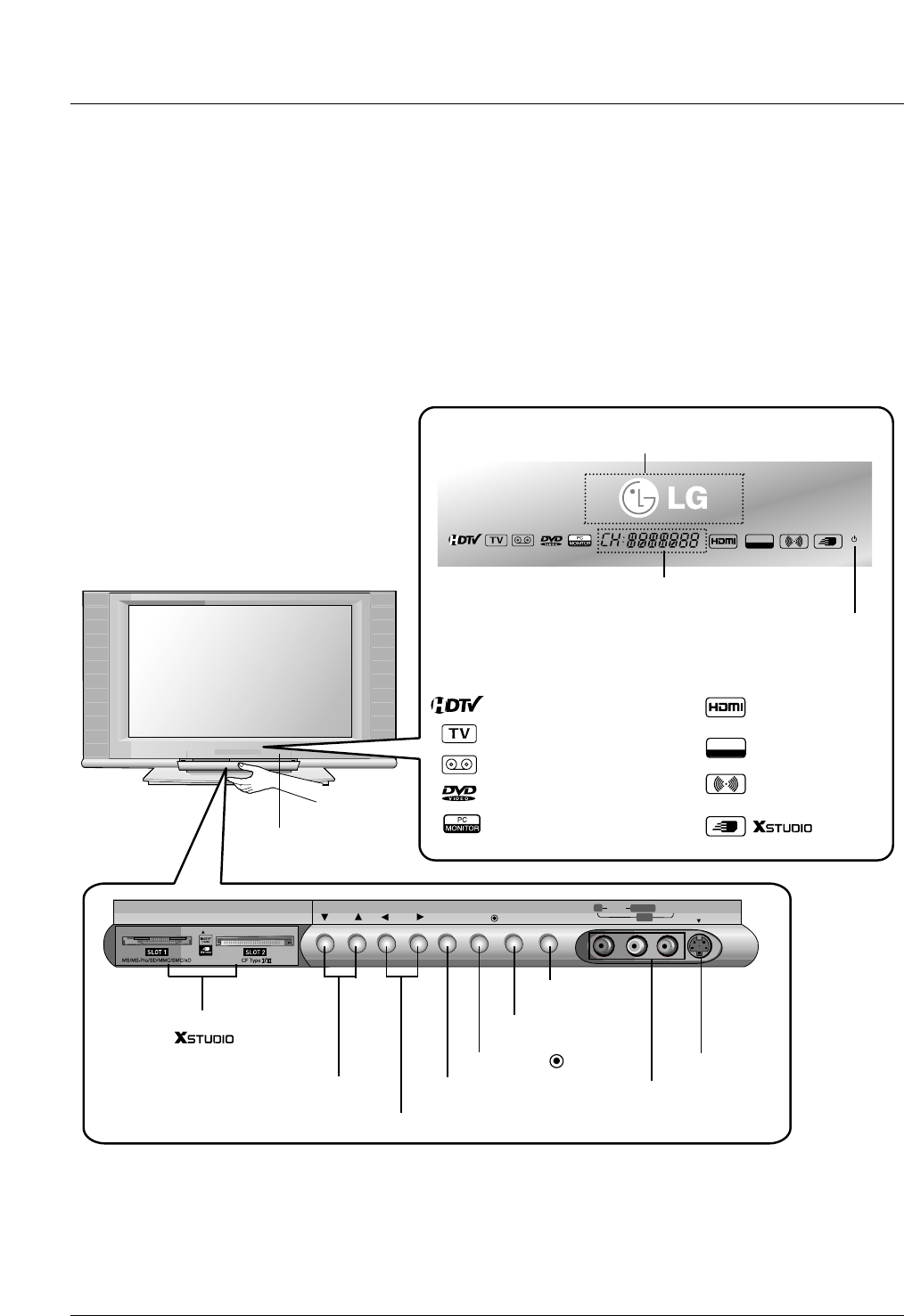
Controls (Model Name: 32/37/42LP1D)
(Model Name: 32/37/42LP1D)
- This is a simplified representation of front panel.
- Here shown may be somewhat different from your TV.
CH VOL
TV/VIDEO/
TV
GUIDE ON/OFF
RRAUDIOAUDIO VIDEOVIDEO S-VIDEOS-VIDEO
L/MONOL/MONO
IN2
MENU
1394
IEEE
Power Standby Indicator
Illuminates red when the TV is in standby mode. When the TV
is switched on, blinks green and then illuminates green.
Remote Control Sensor
TV GUIDE Button
VOLUME (F,G) Buttons
CHANNEL (E, D) Buttons
Memory Card Slot
(For mode)
MENU Button
ON/OFF Button
S-VIDEO Input
Audio/Video Input 2
Logo Display Lamp
Channel Display
TV/VIDEO /Button
DTV, CADTV mode
TV, CATV, DTV, CADTV mode
Video1-2 mode
Component1-2 mode
PC mode
HDMI mode
IEEE1394
Stereo mode
mode
1394
IEEE
Introduction
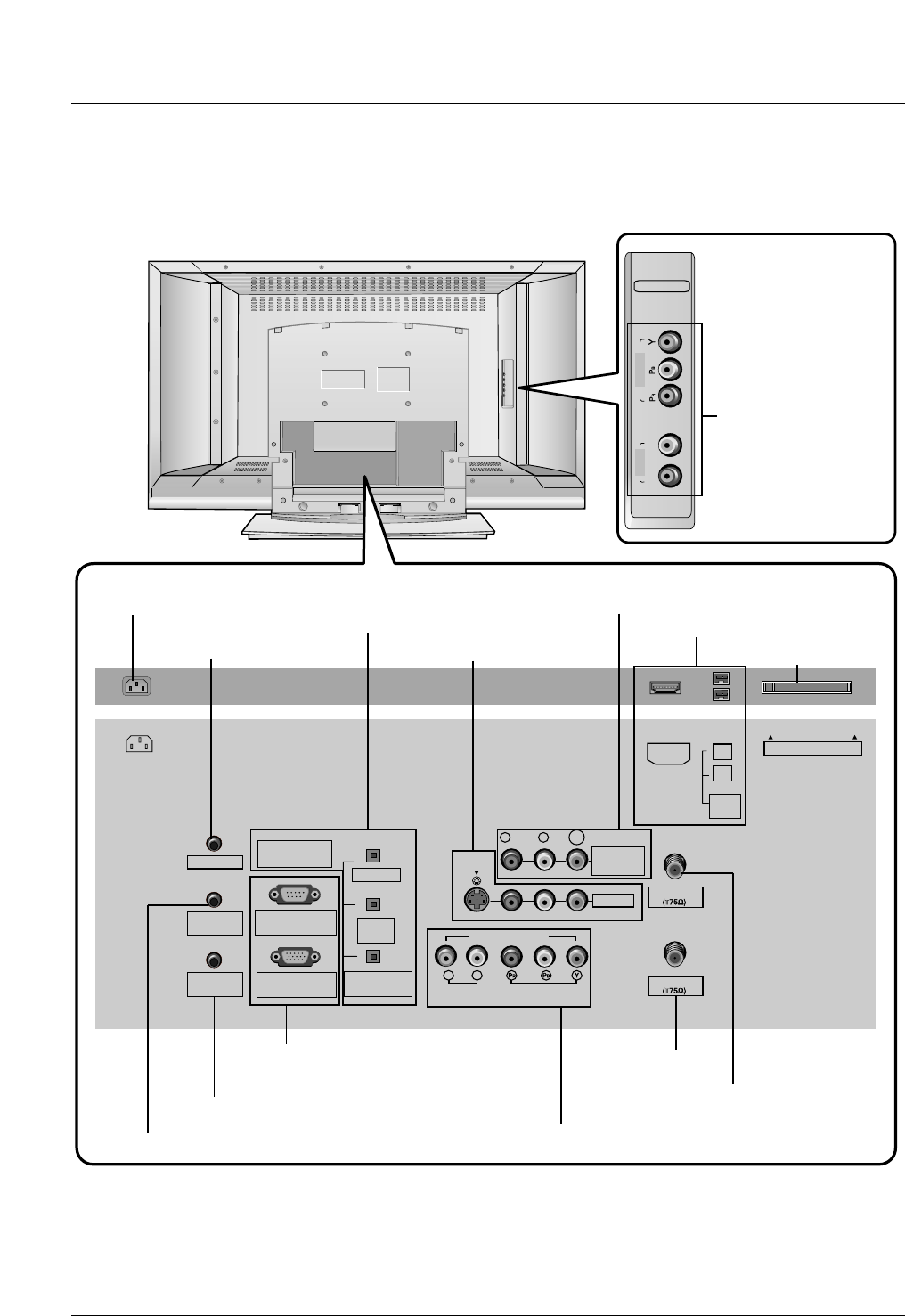
Connection Options (Model Name: 32/37/42LP1D)
Connection Options (Model Name: 32/37/42LP1D)
RL
COMPONENT2
VIDEO
AUDIO
ANTENNA
G-LINK
DIGITAL AUDIO
(OPTICAL)
DVI
INPUT
COMPONENT1
INPUT
OUTPUT
VIDEO1
RGB INPUT
(PC/DTV INPUT)
RS-232C INPUT
(CONTROL/SERVICE)
AUDIO INPUT
AUDIO
(MONO)
VIDEO INPUT
COMPONENT1
RL
RL
PC AUDIO
INPUT
REMOTE
CONTROL
S-VIDEO
CableCARD
IEEE
1394
CABLE
AC IN
MONITOR
OUT
VIDEO
HDMI
* The HDMI port can receive video via High-Definition Multimedia Interface (HDMI) or the Digital Visual Interface
(DVI). Note: An adapter or special cable is required to plug DVI into an HDMI port (available at home theater or
computer stores).
COMPONENT2
(VIDEO / AUDIO Input)
DIGITAL AUDIO OUTPUT
/ DVI INPUT
/ COMPONENT1 INPUT
AUDIO/VIDEO INPUT1
COMPONENT1 (VIDEO / AUDIO INPUT)
MONITOR OUT
HDMI / IEEE1394 Port
CableCARDTM Slot
ANTENNA Input
CABLE Input
AC IN
G-LINKTM Port
PC AUDIO INPUT
RS-232C INPUT (CONTROL/SERVICE) /
RGB INPUT (PC/DTV INPUT)
REMOTE CONTROL Port
21
Installation
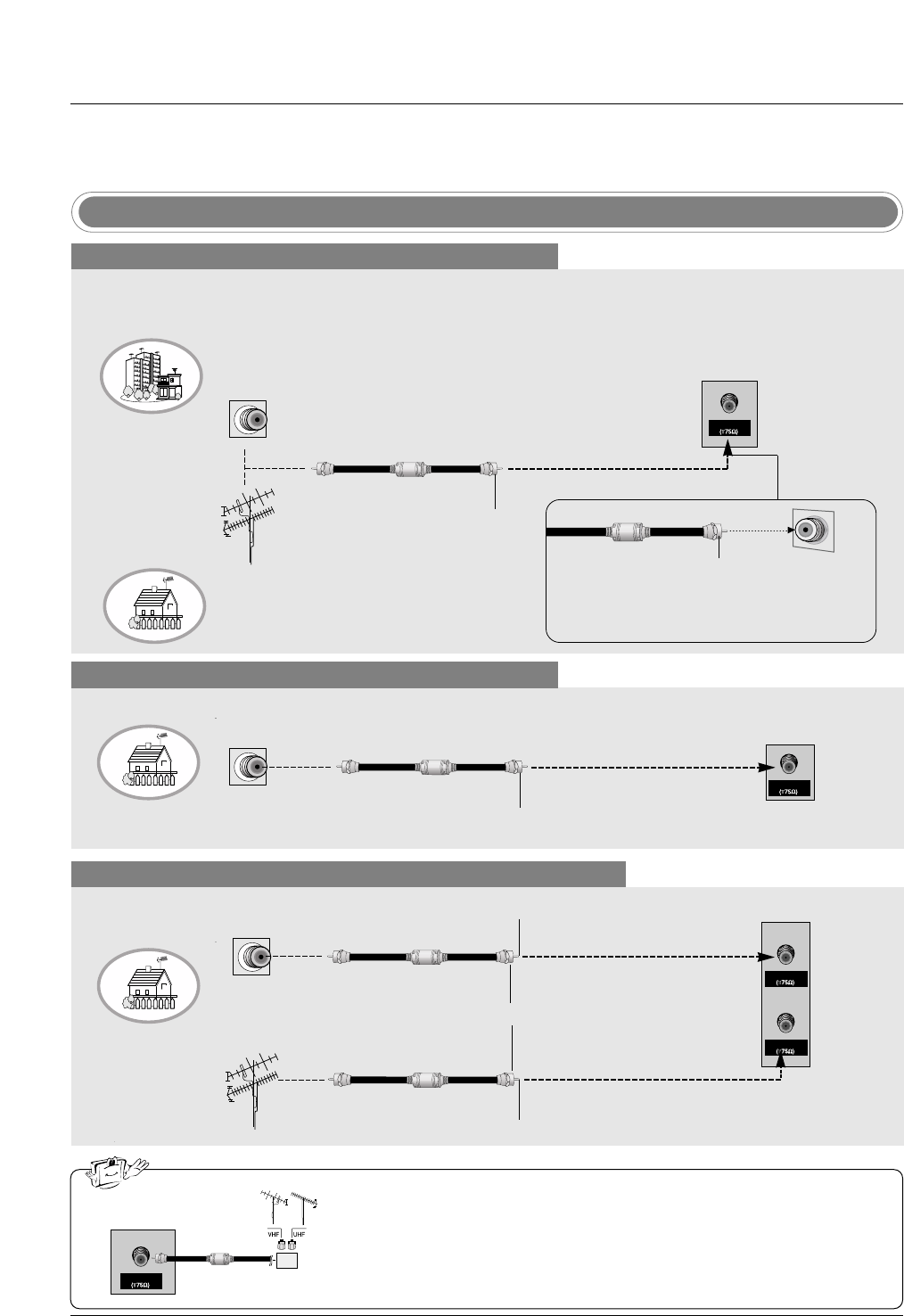
Antenna or Cable Connection
Multi-family Dwellings/Apartments
(Connect to wall antenna socket)
Single-family Dwellings /Houses
(Connect to wall jack for outdoor antenna)
Outdoor Antenna
Wall Antenna Socket
VHF Antenna
UHF Antenna
RF Coaxial Wire (75 ohm)
Turn clockwise to tighten.
ANTENNA
Bronze Wire
Be careful not to bend the bronze wire when
connecting the antenna.
Analog and Digital TV signals provided on antenna
- Antenna or Cable Service without a Cable Box Connection.
- For optimum picture quality, adjust antenna direction if needed.
Cable TV Wall Jack
RF Coaxial Wire (75 ohm)
Turn clockwise to tighten.
CABLE
Analog and Digital TV signals provided on cable
ANTENNA
CABLE
Analog and Digital TV signals provided on cable and antenna
Cable TV Wall Jack
RF Coaxial Wire (75 ohm)
Bronze Wire
Bronze Wire
Turn clockwise to tighten.
Antenna
RF Coaxial Wire (75 ohm)
• In a poor signal area to improve picture quality, purchase and install a sig-
nal amplifier.
• If the antenna needs to be split for two TV’s, install a “2-Way Signal Splitter”
in the connections.
• If the antenna is not installed properly, contact your dealer for assistance.
ANTENNA
External Equipment Connections
External Equipment Connections
signal
amplifier
Installation
NOTE: All cables shown are not included with the TV.
- To avoid picture noise (interference), leave an adequate distance between the VCR and TV.
- Typically a frozen still picture from a VCR. If the 4:3 picture format is used; the fixed images on the sides
of the screen may remain visible on the screen.
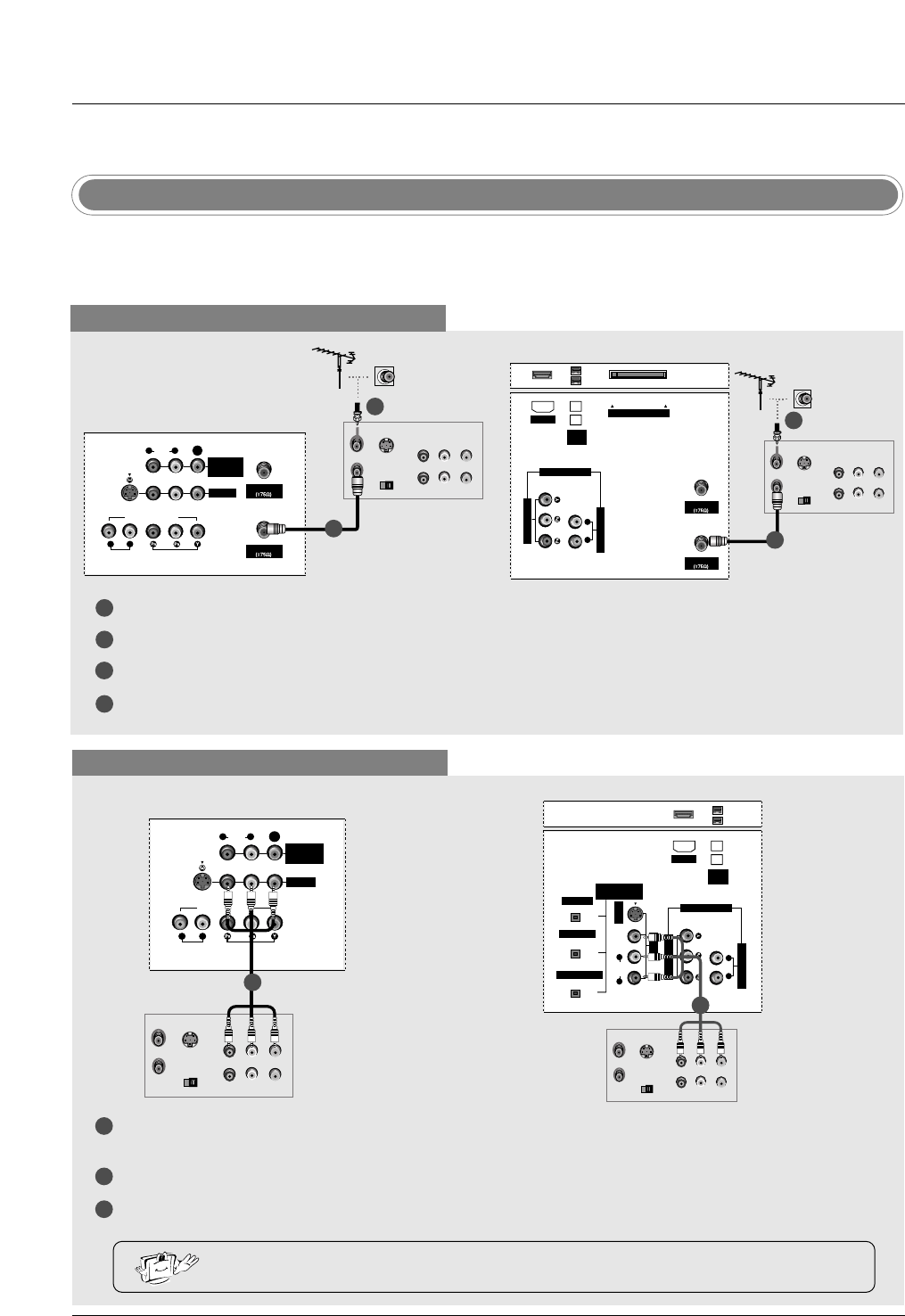
VCR Setup
When connecting with an antenna
1
2
3
4
S-VIDEO OUT
IN
(R) AUDIO (L) VIDEO
34
OUTPUT
SWITCH
ANT OUT
ANT IN
ANTENNA
VIDEO1
AUDIO INPUT
AUDIO
(MONO)
VIDEO INPUT
COMPONENT1
RL
RL
S-VIDEO
CABLE
MONITOR
OUT
VIDEO
Connect the RF antenna out socket of the VCR to the Antenna socket on the set.
Connect the antenna cable to the RF antenna in socket of the VCR.
Set VCR output switch to 3 or 4 and then tune TV to the same channel number.
Insert a video tape into the VCR and press PLAY on the VCR. (Refer to the VCR owner’s manual.)
VCR
When connecting with a RCA cable
S-VIDEO OUT
IN
(R) AUDIO (L) VIDEO
34
OUTPUT
SWITCH
ANT OUT
ANT IN
VIDEO1
AUDIO INPUT
AUDIO
(MONO)
VIDEO INPUT
COMPONENT1
RL
RL
S-VIDEO
MONITOR
OUT
VIDEO
VCR VCR
32, 37, 42 inch TV Back
26 inch TV Back
32, 37, 42 inch TV Back
1
2
3
Connect the AUDIO/VIDEO jacks between TV and VCR. Match the jack colors (Video = yellow, Audio Left
= white, and Audio Right = red)
Insert a video tape into the VCR and press PLAY on the VCR. (Refer to the VCR owner’s manual.)
Select Video1 input source using the TV/VIDEO button on the remote control.
- If connected to IN2 (or VIDEO2), select Video2 input source.
• If you have a mono VCR, connect the audio cable from the VCR to the AUDIO L/MONO jack
of the set.
1
2
ANTENNA
AUDIO INPUT
VIDEO INPUT
RL
CableCARD
IEEE
1394
CABLE
HDMI
COMPONENT1
S-VIDEO OUT
IN
(R) AUDIO (L) VIDEO
34
OUTPUT
SWITCH
ANT OUT
ANT IN
DIGITAL AUDIO
(OPTICAL)
OUTPUT
VIDEO1
AUDIO INPUT
VIDEO INPUT
RL
S-VIDEO
IEEE
1394
AUDIO VIDEO
(MONO)
RL
HDMI
DVI INPUT
COMPONENT1 INPUT
COMPONENT1
S-VIDEO OUT
IN
(R) AUDIO (L) VIDEO
34
OUTPUT
SWITCH
ANT OUT
ANT IN
VCR
2
1
1
26 inch TV Back
1
NOTE: All cables shown are not included with the TV
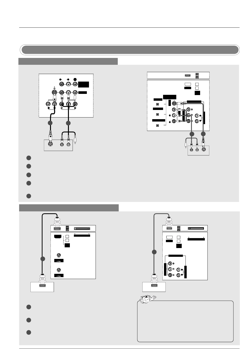
DVD Setup
When connecting with a S-Video cable
VIDEO1
AUDIO INPUT
AUDIO
(MONO)
VIDEO INPUT
COMPONENT1
RL
RL
S-VIDEO
MONITOR
OUT
VIDEO
S-VIDEO (R) AUDIO (L)
DIGITAL AUDIO
(OPTICAL)
OUTPUT
VIDEO1
AUDIO INPUT
VIDEO INPUT
RL
S-VIDEO
IEEE
1394
AUDIO VIDEO
(MONO)
RL
HDMI
DVI INPUT
COMPONENT1 INPUT
COMPONENT1
S-VIDEO
(R) AUDIO (L)
DVD
DVD
1
1
2
2
1
2
3
4
5
Connect the S-VIDEO output of the DVD to the S-VIDEO input on the set.
Connect the audio outputs of the DVD to the AUDIO input jacks on the set.
Turn on the DVD player, insert a DVD.
Select Video1 input source with using the TV/VIDEO button on the remote control.
- If connected to IN2 (or VIDEO2), select Video 2 input source.
Refer to the DVD player's manual for operating instructions.
When connecting with a HDMI cable
1
2
3
Connect the HDMI output of the DVD to the HDMI
jack on the set.
Select HDMI input source with using the
TV/VIDEO button on the remote control.
Refer to the DVD player's manual for operating
instructions.
ANTENNA
CableCARD
IEEE
1394
CABLE
HDMI
HDMI-DVD OUPUT
HDMI-DVD OUPUT
AUDIO INPUT
VIDEO INPUT
RL
CableCARD
IEEE
1394
HDMI
COMPONENT1
DVD DVD
1
1
• TV can receive the video and audio signal simulta-
neously with using a HDMI cable.
• If the DVD supports Auto HDMI function, the DVD
output resolution will be automatically set to
1280x720p.
• If the DVD does not support Auto HDMI, you need
to set the output resolution appropriately. To get the
best picture quality, adjust the output resolution of
the DVD to 1280x720p.
32, 37, 42 inch TV Back 26 inch TV Back
32, 37, 42 inch TV Back 26 inch TV Back
25
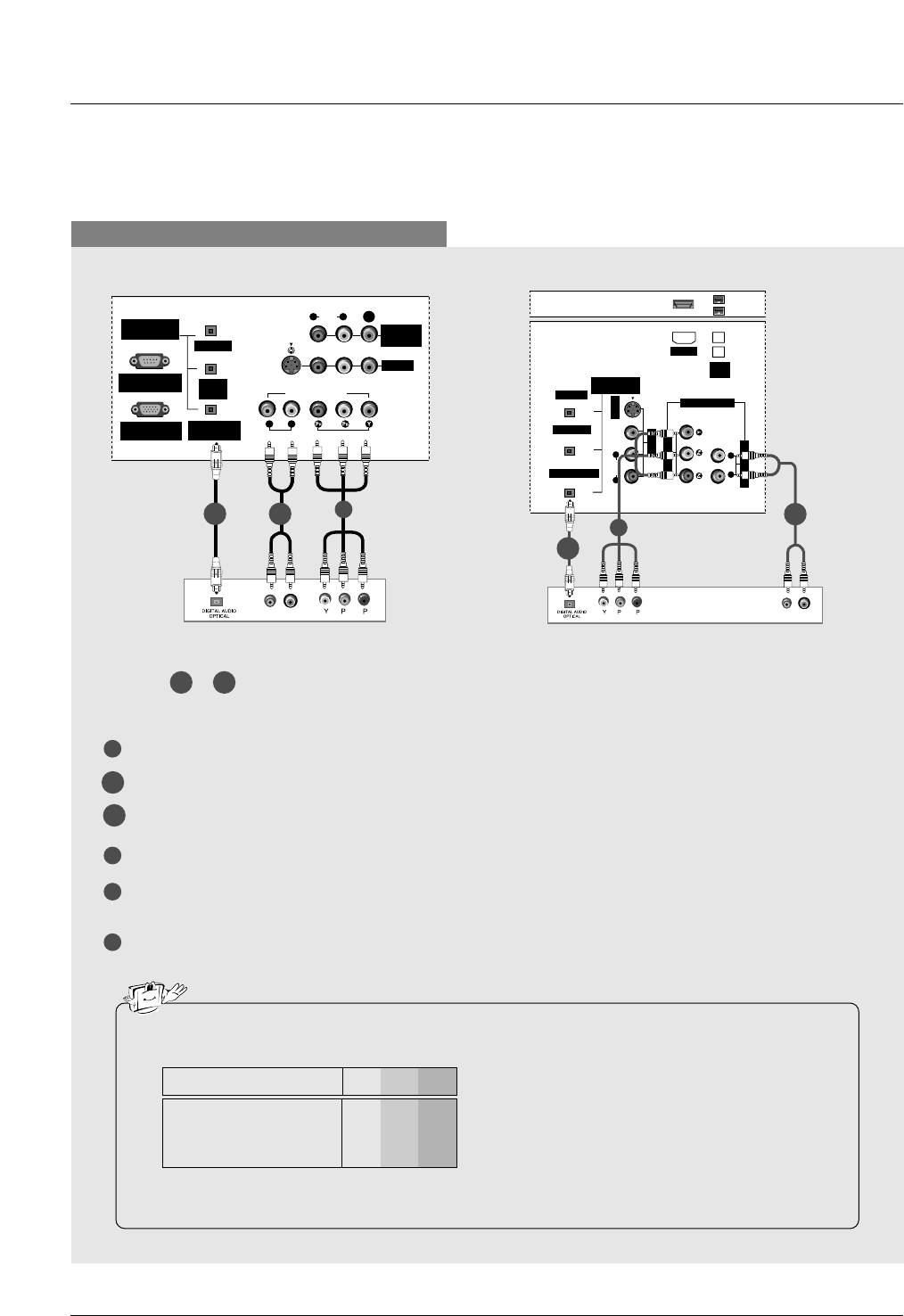
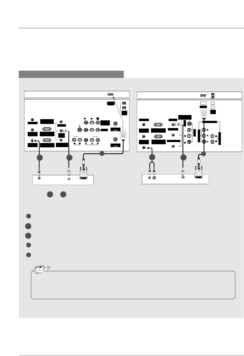
When connecting with a component cable
1
3
4
5
Connect the video outputs (Y, PB, PR) of the DVD to the COMPONENT1 VIDEO INPUT jacks on the set.
Connect the audio outputs of the DVD to the COMPONENT1 AUDIO INPUT jacks on the set.
Connect the optical audio output of the DVD to the DIGITAL AUDIO COMPONENT1 INPUT jack on the set.
Turn on the DVD player, insert a DVD.
Select Component 1 input source with using the TV/VIDEO button on the remote control.
- If connected to COMPONENT2 input, select Component 2 input source.
Refer to the DVD player's manual for operating instructions.
•Component Input ports
To get better picture quality, connect a DVD player to the component input ports as shown below.
• Digital Audio will not work for Component 2 input source.
• Digital Audio operation has priority if Digital Audio and AUDIO L/R are connected at the same time.
Y PBPR
Component ports on the TV
Y
Y
Y
Y
Pb
B-Y
Cb
PB
Pr
R-Y
Cr
PR
Video output ports
on DVD player
BR
(R) AUDIO (L)
DIGITAL AUDIO
(OPTICAL)
DVI
INPUT
COMPONENT1
INPUT
OUTPUT
VIDEO1
RGB INPUT
(PC/DTV INPUT)
RS-232C INPUT
(CONTROL/SERVICE)
AUDIO INPUT
AUDIO
(MONO)
VIDEO INPUT
COMPONENT1
RL
RL
S-VIDEO
MONITOR
OUT
VIDEO
DIGITAL AUDIO
(OPTICAL)
OUTPUT
VIDEO1
AUDIO INPUT
VIDEO INPUT
RL
S-VIDEO
IEEE
1394
AUDIO VIDEO
(MONO)
RL
HDMI
DVI INPUT
COMPONENT1 INPUT
COMPONENT1
BR
(R) AUDIO (L)
DVD DVD
1
Select or , depending on your DVD connector.
2-1
2-1
2-1 2-2
2-2
1
2-1
2-2
2-2
32, 37, 42 inch TV Back 26 inch TV Back
Installation
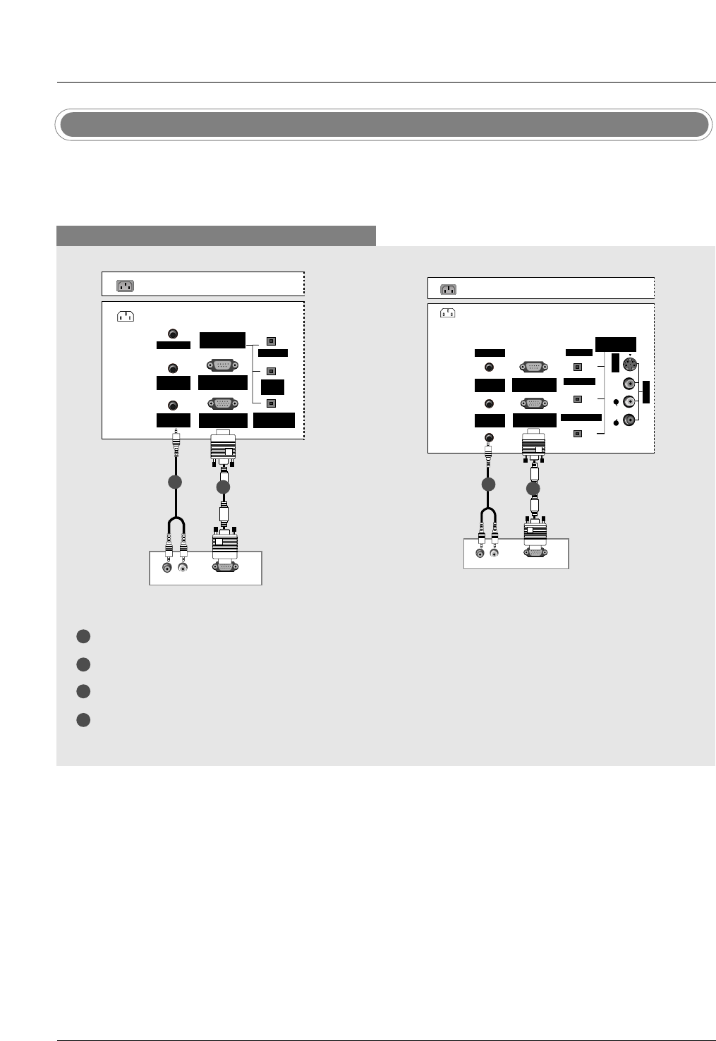
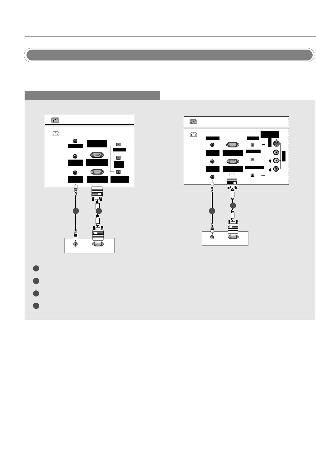
When connecting with a D-sub 15 pin cable
1
2
3
4
Connect the RGB output of the digital set-top box to the RGB INPUT (PC/DTV INPUT) jack on the set.
Connect the audio outputs of the set-top box to the PC AUDIO INPUT jack on the set.
Turn on the digital set-top box. (Refer to the owner’s manual for the digital set-top box.)
Select RGB-DTV input source with using the TV/VIDEO button on the remote control.
- This TV can receive Digital Over-the-air/Cable signals without an external digital set-top box. However, if
you do receive Digital signals from a digital set-top box or other digital external device, refer to the figure
as shown below.
AC IN
G-LINK
DIGITAL AUDIO
(OPTICAL)
DVI
INPUT
COMPONENT1
INPUT
OUTPUT
RGB INPUT
(PC/DTV INPUT)
RS-232C INPUT
(CONTROL/SERVICE)
PC AUDIO
INPUT
REMOTE
CONTROL
RGB-DTV OUPUT
(R) AUDIO (L)
G-LINK
DIGITAL AUDIO
(OPTICAL)
OUTPUT
VIDEO1
RGB INPUT
(PC/DTV INPUT)
RS-232C INPUT
(CONTROL/SERVICE)
PC AUDIO
INPUT
REMOTE
CONTROL
S-VIDEO
AC IN
AUDIO VIDEO
(MONO)
RL
DVI INPUT
COMPONENT1 INPUT
RGB-DTV OUPUT
(R) AUDIO (L)
Digital Set-top Box
Digital Set-top Box
HDSTB Setup
1
21
2
32, 37, 42 inch TV Back 26 inch TV Back
Installation
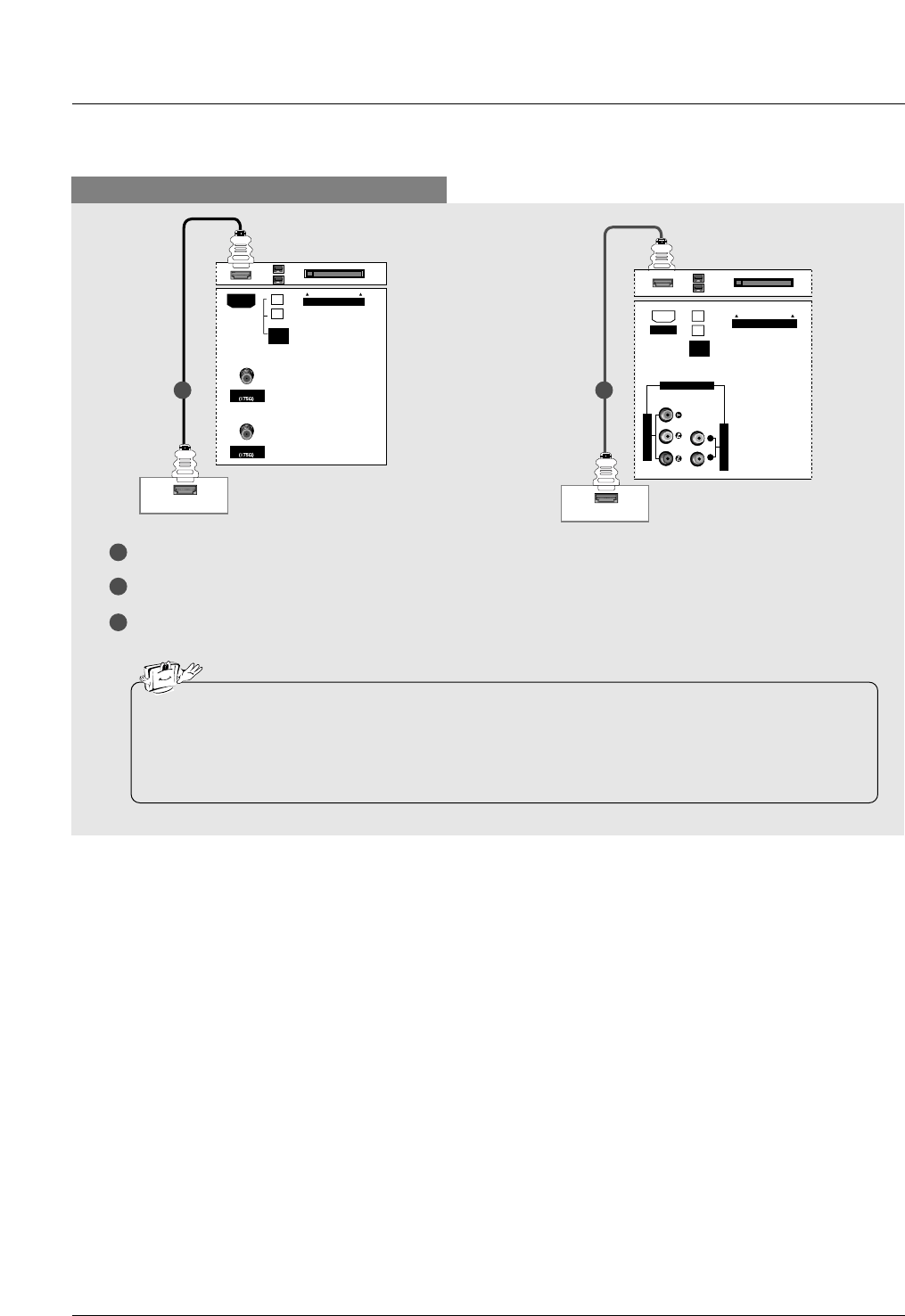
When connecting with a HDMI cable
1
2
3
Connect the HDMI output of the digital set-top box to the HDMI jack on the set.
Select HDMI/DVI input source with using the TV/VIDEO button on the remote control.
Turn on the digital set-top box. (Refer to the owner’s manual for the digital set-top box.)
ANTENNA
CableCARD
CABLE
HDMI-DTV OUPUT
IEEE
1394
HDMI
HDMI-DTV OUPUT
AUDIO INPUT
VIDEO INPUT
RL
CableCARD
IEEE
1394
HDMI
COMPONENT1
Digital Set-top Box Digital Set-top Box
1 1
• TV can receive the video and audio signal simultaneously with using a HDMI cable.
• If the digital set-top box supports Auto HDMI function, output resolution of the digital set-top box will be auto-
matically set to 1280x720p.
• If the digital set-top box does not support Auto HDMI, you need to set the output resolution appropriately. To get
the best picture quality, adjust the output resolution of the digital set-top box to 1280x720p.
32, 37, 42 inch TV Back 26 inch TV Back
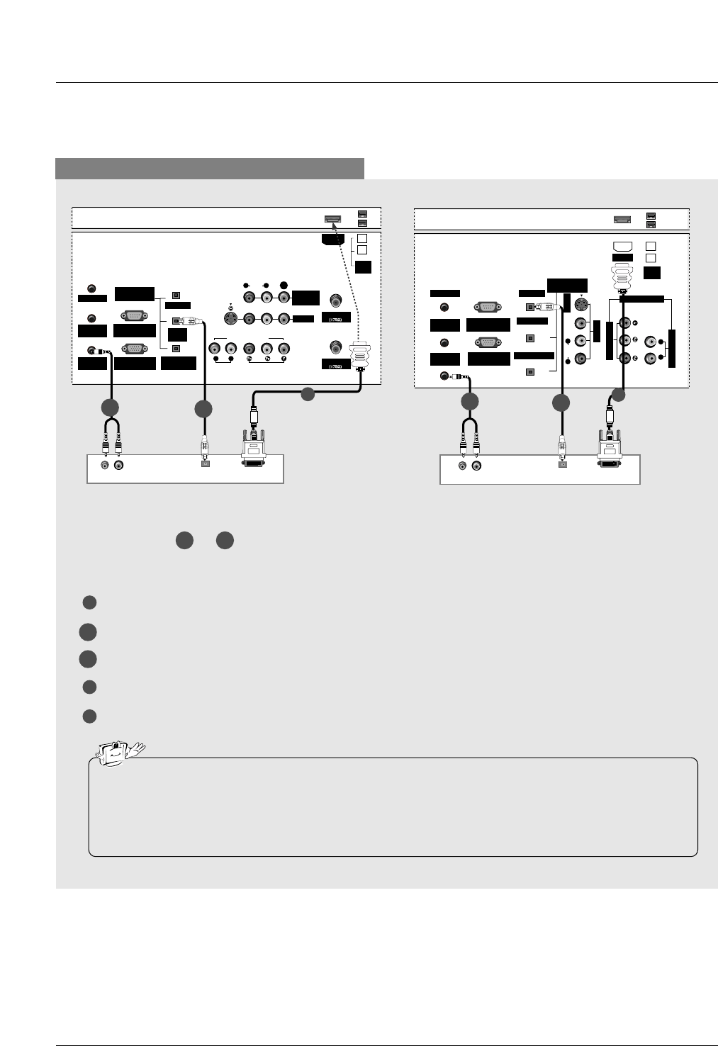
Installation
When connecting with a HDMI to DVI cable
1
4
5
Connect the DVI output of the digital set-top box to the HDMI jack on the set.
Connect the audio output of the digital set-top box to the PC AUDIO INPUT jack on the set.
Connect the optical audio output of the digital set-top box to the DIGITAL AUDIO DVI INPUT jack on the set.
Turn on the digital set-top box. (Refer to the owner’s manual for the digital set-top box.)
Select HDMI/DVI input source with using the TV/VIDEO button on the remote control.
(R) AUDIO (L) DIGITAL AUDIO
OPTICAL
DVI-DTV OUTPUT
ANTENNA
G-LINK
DIGITAL AUDIO
(OPTICAL)
DVI
INPUT
COMPONENT1
INPUT
OUTPUT
VIDEO1
RGB INPUT
(PC/DTV INPUT)
RS-232C INPUT
(CONTROL/SERVICE)
AUDIO INPUT
AUDIO
(MONO)
VIDEO INPUT
COMPONENT1
RL
RL
PC AUDIO
INPUT
REMOTE
CONTROL
S-VIDEO
CABLE
MONITOR
OUT
VIDEO
IEEE
1394
HDMI
(R) AUDIO (L) DIGITAL AUDIO
OPTICAL
DVI-DTV OUTPUT
G-LINK
DIGITAL AUDIO
(OPTICAL)
OUTPUT
VIDEO1
RGB INPUT
(PC/DTV INPUT)
RS-232C INPUT
(CONTROL/SERVICE)
AUDIO INPUT
VIDEO INPUT
RL
PC AUDIO
INPUT
REMOTE
CONTROL
S-VIDEO
IEEE
1394
AUDIO VIDEO
(MONO)
RL
HDMI
DVI INPUT
COMPONENT1 INPUT
COMPONENT1
Digital Set-top Box Digital Set-top Box
1
2-1 2-2
1
2-1 2-2
Select or , depending on your digital set-top box connector.
2-1 2-2
• If the digital set-top box has a DVI output and no HDMI output, a separated audio connection is necessary.
• If the digital set-top box supports Auto DVI function, the output resolution of the digital set-top box will be auto-
matically set to 1280x720p.
• If the digital set-top box does not support Auto DVI, you need to set the output resolution appropriately. To get the
best picture quality, adjust the output resolution of the digital set-top box to 1280x720p.
2-1
2-2
32, 37, 42 inch TV Back 26 inch TV Back
Installation
Digital Audio Output
RL
AUDIO VIDEO
R
(MONO)
L VIDEO
S-VIDEO
VIDEO AUDIO
COMPONENT 2 VIDEO 2
Camcorder
Video Game Set
TV Side
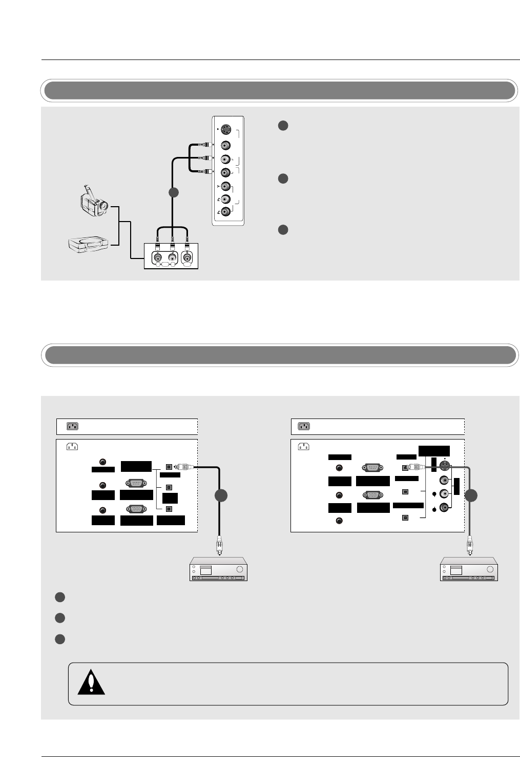
1
1
2
3
Connect the AUDIO/VIDEO jacks between TV
and external equipment. Match the jack colors
(Video = yellow, Audio Left = white, and Audio
Right = red).
Select Video2 input source with using the
TV/VIDEO button on the remote control.
- If connected to VIDEO1 input, select Video1
input source.
Operate the corresponding external equipment.
Refer to external equipment operating guide. For
connection instructions to operate the TV Guide
On Screen system, see page 42~43.
1
2
3
Connect one end of an optical cable to the TV Digital Audio Optical Output port.
Connect the other end of the optical cable to the digital audio optical input on the audio equipment.
See the external audio equipment instruction manual for operation. When connecting with external audio
equipments, such as amplifers or speakers, please turn the TV speakers off.(Refer to p.80)
AC IN
G-LINK
DIGITAL AUDIO
(OPTICAL)
DVI
INPUT
COMPONENT1
INPUT
OUTPUT
RGB INPUT
(PC/DTV INPUT)
RS-232C INPUT
(CONTROL/SERVICE)
PC AUDIO
INPUT
REMOTE
CONTROL
G-LINK
DIGITAL AUDIO
(OPTICAL)
OUTPUT
VIDEO1
RGB INPUT
(PC/DTV INPUT)
RS-232C INPUT
(CONTROL/SERVICE)
PC AUDIO
INPUT
REMOTE
CONTROL
S-VIDEO
AUDIO VIDEO
(MONO)
RL
DVI INPUT
COMPONENT1 INPUT
AC IN
- Send the TV’s audio to external audio equipment (stereo system) via the Digital Audio Output Optical port.
CAUTION
Do not look into the optical output port. Looking at the laser beam may damage your vision.
External AV Source Setup
1/2 1/2
32, 37, 42 inch TV Back 26 inch TV Back
Installation
Monitor Out Setup (32LX1D/2D, 32/37/42LP1D only)
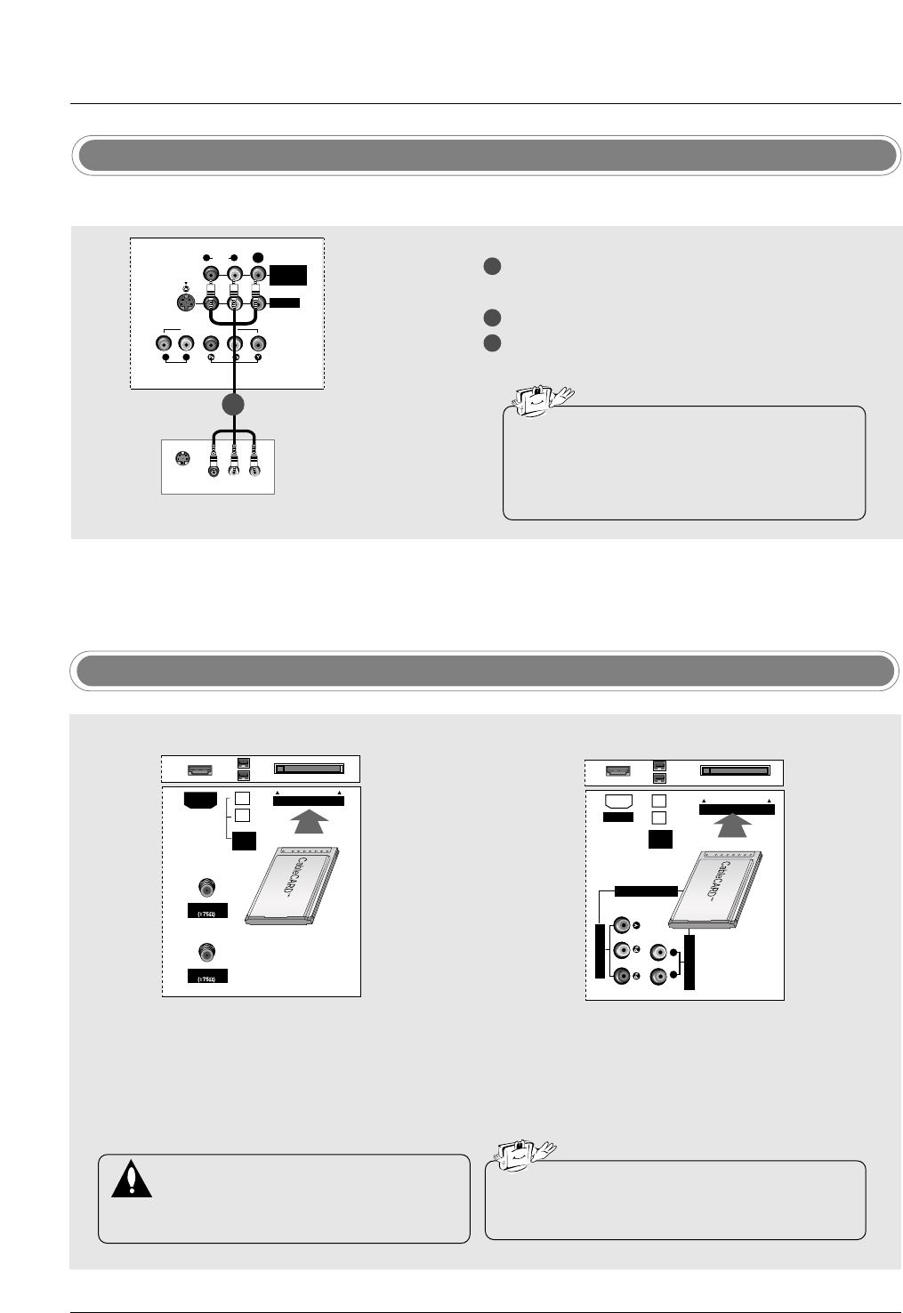
1
2
2
Connect the second TV or monitor to the TV’s
MONITOR OUTPUT jacks.
See the Operating Manual of the second TV or
monitor for further details regarding that device’s
input settings.
VIDEO1
AUDIO INPUT
AUDIO
(MONO)
VIDEO INPUT
COMPONENT1
RL
RL
S-VIDEO
MONITOR
OUT
VIDEO
S-VIDEO IN
(R) AUDIO (L)
VIDEO
- The TV has a special signal output capability which allows you to hook up a second TV or monitor.
1/2
Second TV
• Component1/2 input sources can be used for
Monitor out.
• When connecting with external audio equipments,
such as amplifers or speakers, please turn the TV
speakers off.(Refer to p.80)
CableCARDTM Setup
- To view the premium stations
Insert the CableCARDTM received from Cable Service provider to CableCARD slot of TV as shown. If
the pairing information about this TV and the CableCARD is automatically displayed on the screen,
contact with Cable service provider by phone.
• Different card types can be used with this unit
(Motorola, Scientific Atlanta, SCM, etc.).
Caution:
When removing the CableCARDTM, do not
drop it as this may cause damage to the
card.
ANTENNA
CableCARD
CABLE
IEEE
1394
HDMI
AUDIO INPUT
VIDEO INPUT
RL
CableCARD
IEEE
1394
HDMI
COMPONENT1
32, 37, 42 inch TV Back 26 inch TV Back
Installation
- This TV provides Plug and Play capability, meaning that the PC adjusts automatically to the TV's settings.
The TV sends configuration information (EDID) to the PC using the Video Electronics Standard Association
(VESA) Display Data Channel (DDC) protocol.
PC Setup
When connecting with a D-sub 15 pin cable
1
2
3
4
Connect the RGB output of the PC to the RGB INPUT (PC/DTV INPUT) jack on the set.
Connect the PC audio output to the PC AUDIO INPUT jack on the set.
Turn on the PC and the set.
Select RGB-PC input source with using the TV/VIDEO button on the remote control.
AC IN
G-LINK
DIGITAL AUDIO
(OPTICAL)
DVI
INPUT
COMPONENT1
INPUT
OUTPUT
RGB INPUT
(PC/DTV INPUT)
RS-232C INPUT
(CONTROL/SERVICE)
PC AUDIO
INPUT
REMOTE
CONTROL
RGB-PC OUPUT
AUDIO
AC IN
RGB-PC OUPUT
AUDIO
G-LINK
DIGITAL AUDIO
(OPTICAL)
OUTPUT
VIDEO1
RGB INPUT
(PC/DTV INPUT)
RS-232C INPUT
(CONTROL/SERVICE)
PC AUDIO
INPUT
REMOTE
CONTROL
S-VIDEO
AUDIO VIDEO
(MONO)
RL
DVI INPUT
COMPONENT1 INPUT
1
2
1
2
PC
PC
32, 37, 42 inch TV Back 26 inch TV Back
Installation
When connecting with a HDMI to DVI cable
1
3
4
Connect the DVI output of the PC to the HDMI jack on the set.
Connect the PC audio output to the PC AUDIO INPUT jack on the set.
Connect the PC optical audio output to the DIGITAL AUDIO DVI INPUT jack on the set.
Turn on the PC and the set.
Select HDMI/DVI input source with using the TV/VIDEO button on the remote control.
DIGITAL AUDIO
OPTICAL
DVI-PC OUTPUT
AUDIO
ANTENNA
G-LINK
DIGITAL AUDIO
(OPTICAL)
DVI
INPUT
COMPONENT1
INPUT
OUTPUT
VIDEO1
RGB INPUT
(PC/DTV INPUT)
RS-232C INPUT
(CONTROL/SERVICE)
AUDIO INPUT
AUDIO
(MONO)
VIDEO INPUT
COMPONENT1
RL
RL
PC AUDIO
INPUT
REMOTE
CONTROL
S-VIDEO
IEEE
1394
CABLE
MONITOR
OUT
VIDEO
DVI (VIDEO)
HDMI
(R) AUDIO (L) DIGITAL AUDIO
OPTICAL
DVI OUTPUT
G-LINK
DIGITAL AUDIO
(OPTICAL)
OUTPUT
VIDEO1
RGB INPUT
(PC/DTV INPUT)
RS-232C INPUT
(CONTROL/SERVICE)
AUDIO INPUT
VIDEO INPUT
RL
PC AUDIO
INPUT
REMOTE
CONTROL
S-VIDEO
IEEE
1394
AUDIO VIDEO
(MONO)
RL
HDMI
DVI INPUT
COMPONENT1 INPUT
COMPONENT1
1
PC PC
2-1
2-1
2-2
1
2-1 2-2
2-2
Select or , depending on your PC connector.
2-1 2-2
• If the PC has a DVI output and no HDMI output, a separated audio connection is necessary.
• If the PC supports Auto DVI function, the output resolution of the PC will be automatically set to 1280x720p.
• If the PC does not support Auto DVI, you need to set the output resolution appropriately. To get the best picture
quality, adjust the output resolution of PC graphics card's output resolution to 1024x768, 60Hz.
32, 37, 42 inch TV Back 26 inch TV Back
Installation
1. To get the best picture quality, adjust the PC
graphics card to 1024x768, 60Hz.
2. If the graphic card on the PC does not output ana-
log and digital RGB simultaneously, connect only
one of either PC INPUT or DVI INPUT to display
the PC on the TV.
If the graphic card on the PC does output analog
and digital RGB simultaneously, set the TV to
either RGB or DVI; (the other mode is set to Plug
and Play automatically by the TV.)
3. If using a sound card, adjust the PC sound as
required.
4. Depending on the graphics card, DOS mode may
not work if a HDMI to DVI Cable is in use.
5. When Source Devices connected with HDMI1/DVI
Input, output PC Resolution (VGA, SVGA, XGA),
Position and Size may not fit to Screen.Press the
ADJUST button to adjust the screen Position of TV
SET and contact an PC graphics card service cen-
ter.
6. When Source Devices connected with HDMI1/DVI
Input, output TV SET Resolution (480p, 720p,
1080i) and TV SET Display fit EIA/CEA-861-B
Specification to Screen. If not, refer to the Manual
of HDMI1/DVI Source Devices or contact your ser-
vice center.
7. In case HDMI/DVI Source Devices is not connect-
ed Cable or poor cable connection, "NO SIGNAL"
OSD display in HDMI1/DVI Input. In case that
Video Resolution is not supported TV SET output
in HDMI1/DVI Source Devices, "INVALID FOR-
MAT" OSDdisplay. Refer to the Manual of
HDMI1/DVI Source Devices or contact your ser-
vice center.
8. Check the image on your TV. There may be noise
associated with the resolution, vertical pattern,
contrast or brightness in PC, HDMI/DVI mode. If
noise is present, change the PC or HDMI/DVI
mode to another resolution, change the refresh
rate to another rate or adjust the brightness and
contrast on the menu until the picture is clear. If the
refresh rate of the PC graphic card can not be
changed, change the PC graphic card or consult
the manufacturer of the PC graphic card.
9. Avoid keeping a fixed image on the TV's screen for
a long period of time. The fixed image may become
permanently imprinted on the screen.
10.The synchronization input form for Horizontal and
Vertical frequencies is separate.
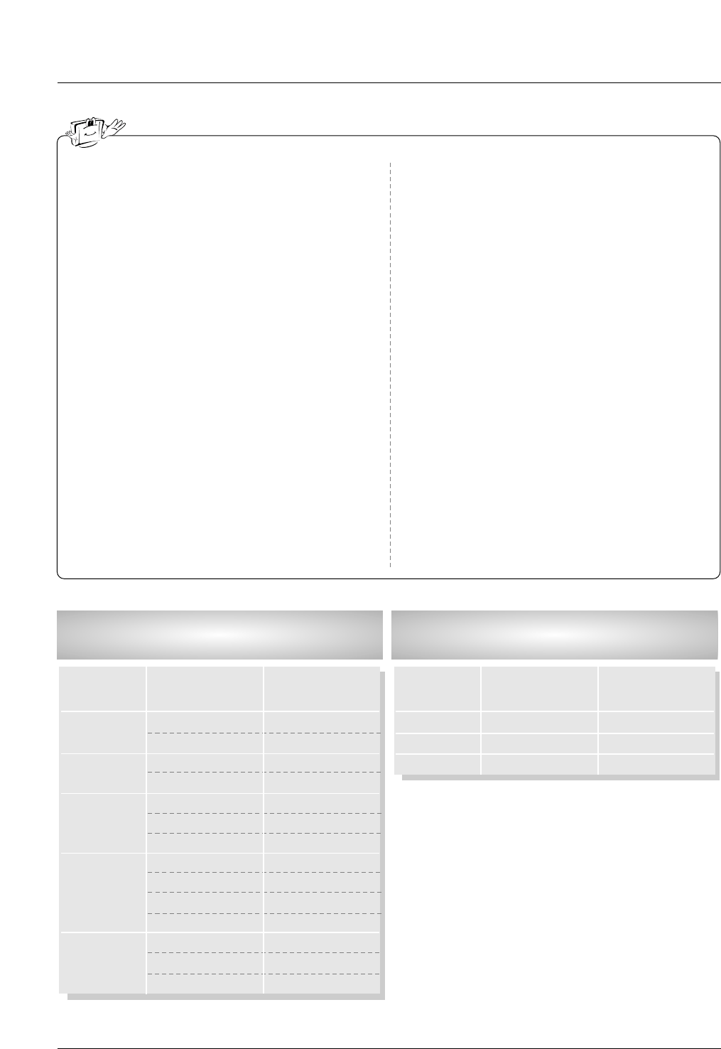
Supported Display Resolution
(RGB-PC, HDMI/DVI Mode)
Resolution
640x350
720x400
640x480
800x600
1024x768
Horizontal
Frequency (kHz)
31.468
37.861
31.469
37.927
31.469
37.861
37.500
35.156
37.879
48.077
46.875
48.363
56.476
60.023
70.09
85.08
70.08
85.03
59.94
72.80
75.00
56.25
60.31
72.18
75.00
60.00
70.06
75.02
Vertical
Frequency (Hz)
Supported Display Resolution
(RGB-DTV, HDMI/DVI Mode)
Resolution
1280x720p
1920x1080i
720x480p
Horizontal
Frequency (kHz)
45
67.5
31.5
60
60
60
Vertical
Frequency (Hz)
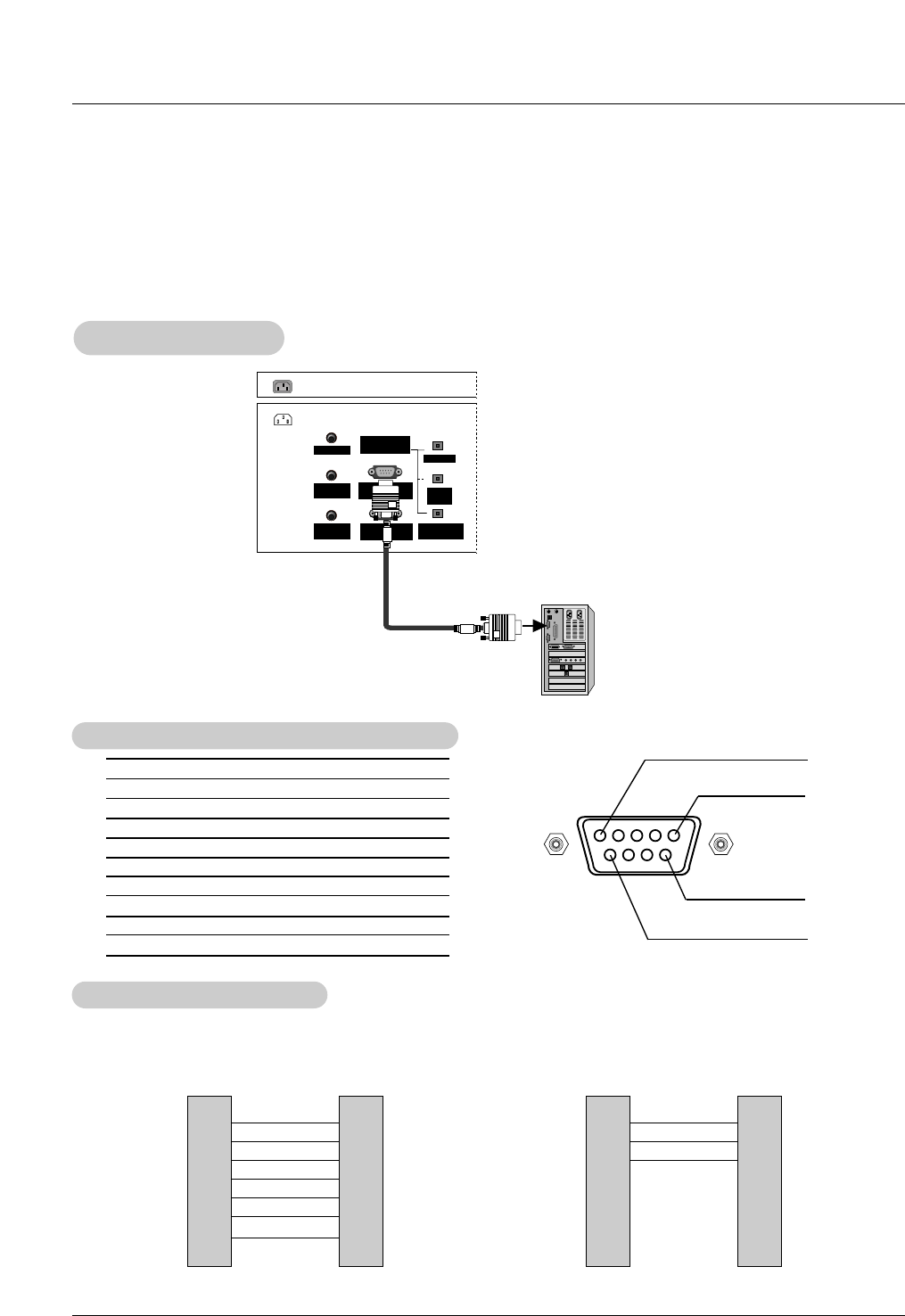
Reference
No. Pin Name
1 No connection
2 RXD (Receive data)
3 TXD (Transmit data)
4 DTR (DTE side ready)
5 GND
6 DSR (DCE side ready)
7 RTS (Ready to send)
8 CTS (Clear to send)
9 No Connection
1
5
6
9
2
3
5
4
6
7
8
RXD
TXD
GND
DTR
DSR
RTS
CTS
TXD
RXD
GND
DSR
DTR
CTS
RTS
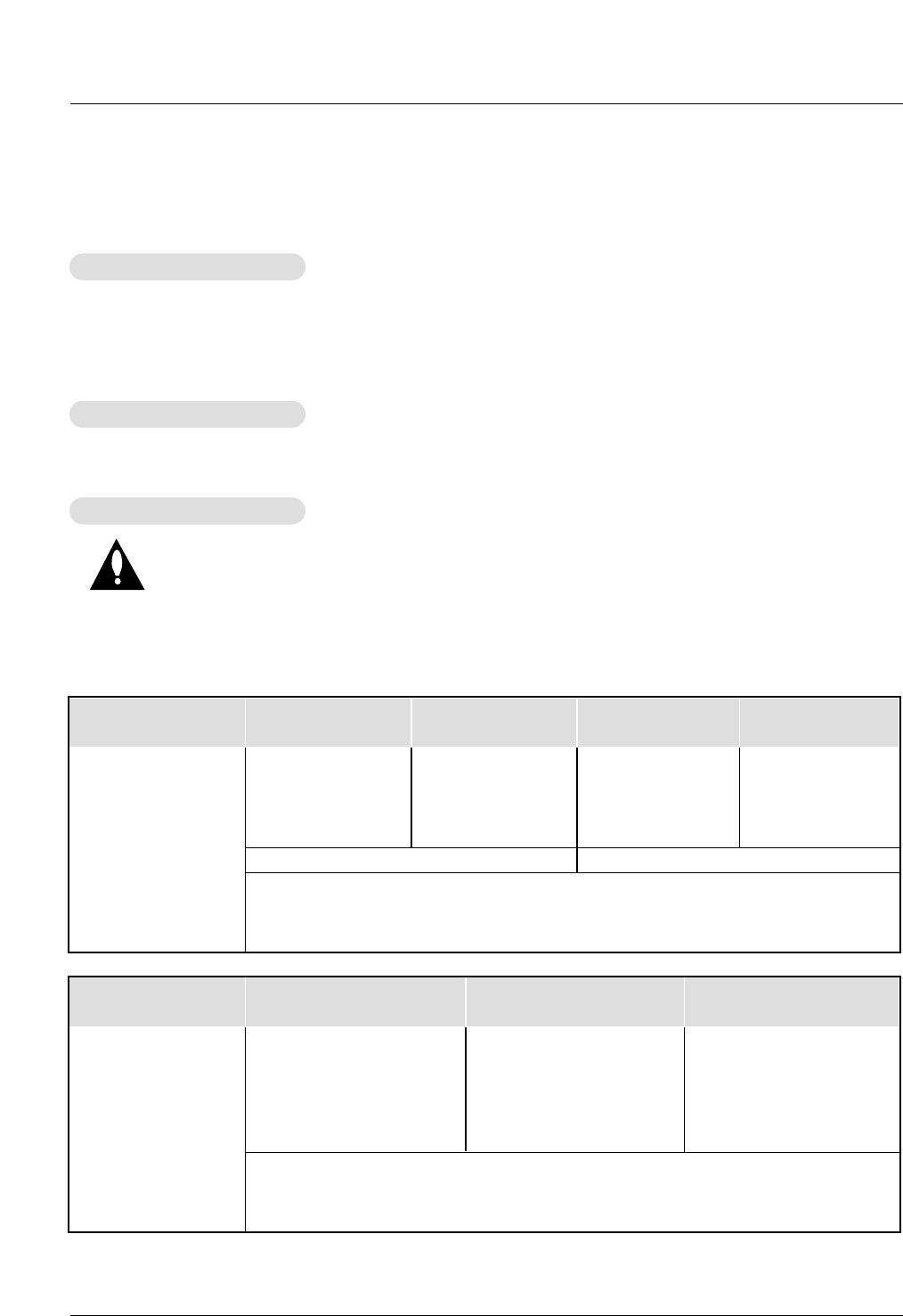
PC
7-Wire Configurations
(Serial female-female NULL modem cable)
D-Sub 9
3
2
5
6
4
8
7
TV
D-Sub 9
2
3
5
4
6
7
8
RXD
TXD
GND
DTR
DSR
RTS
CTS
TXD
RXD
GND
DTR
DSR
RTS
CTS
PC
3-Wire Configurations
(Not standard)
D-Sub 9
3
2
5
4
6
7
8
TV
D-Sub 9
- Connect the RS-232C input jack to an external control device (such as a computer or an A/V control system) and
control the Monitor’s functions externally.
- Connect the serial port of the control device to the RS-232C jack on the TV back panel.
- RS-232C connection cables are not supplied with the TV.
T
Type of Connector; D-Sub 9-Pin Male
ype of Connector; D-Sub 9-Pin Male
RS-232C Configurations
RS-232C Configurations
External Control Device Setup
External Control Device Setup
RS-232C Setup
RS-232C Setup
AC IN
G-LINK
DIGITAL AUDIO
(OPTICAL)
DVI
INPUT
COMPONENT1
INPUT
OUTPUT
RGB INPUT
(PC/DTV INPUT)
RS-232C INPUT
(CONTROL/SERVICE)
PC AUDIO
INPUT
REMOTE
CONTROL
PC
Reference
1. Here’s a great way to keep the dust off your screen for a while. Wet a soft cloth in a mixture of lukewarm water
and a little fabric softener or dish washing detergent. Wring the cloth until it’s almost dry, and then use it to wipe
the screen.
2. Make sure the excess water is off the screen, and then let it air-dry before you turn on your TV.
To remove dirt or dust, wipe the cabinet with a soft, dry, lint-free cloth.
Please be sure not to use a wet cloth.
If you expect to leave your TV dormant for a long time (such as a vacation), it’s a good idea to
unplug the power cord to protect against possible damage from lightning or power surges.
- Early malfunctions can be prevented. Careful and regular cleaning can extend the amount of time you will have
your new TV. Be sure to turn the power off and unplug the power cord before you begin any cleaning.
Cleaning the Screen
Cleaning the Screen
Cleaning the Cabinet
Cleaning the Cabinet
Extended
Extended Absence
Absence
Maintenance
Maintenance
Product Specifications
Product Specifications
•The specifications shown above may be changed without prior notice for quality improvement.
MODEL
Width (inches / mm)
Height (inches / mm)
Depth (inches / mm)
Weight (pounds / kg)
Power requirement
Television System
Program Coverage
External Antenna Impedance
31 / 787.7
20 / 510
7.6 / 193.4
41.2 / 18.7
36.3 / 922
23.6 / 599.7
8.6 / 218.5
54 / 24.5
36.3 / 922
24.1 / 613.4
11.3 / 287.5
56.2 / 25.2
31 / 787.7
19.2 / 487
10 / 253
40 / 18.1
26LX1D 26LX2D 32LX1D 32LX2D
NTSC-M, ATSC
VHF 2 ~ 13, UHF 14 ~ 69, CATV 1 ~ 135, CADTV 1 ~ 135, DTV 2 ~ 69
75 Ω
AC 100-240V~ 50/60Hz 1.5A AC 100-240V~ 50/60Hz 2.0A
MODEL
Width (inches / mm)
Height (inches / mm)
Depth (inches / mm)
Weight (pounds / kg)
Power requirement
Television System
Program Coverage
External Antenna Impedance
40 / 1016
24.7 / 627.5
8.03 / 204
70.5 / 32
AC 100-240V~ 50/60Hz 2.0A
45.6 / 1158
28.3 / 719
8.4 / 213.1
91.5 / 41.5
AC 100-240V~ 50/60Hz 2.4A
50.8 / 1290
31.7 / 804
9.7 / 247.5
101.4 / 46
AC 100-240V~ 50/60Hz 3.5A
32LP1D 37LP1D 42LP1D
NTSC-M, ATSC
VHF 2 ~ 13, UHF 14 ~ 69, CATV 1 ~ 135, CADTV 1 ~ 135, DTV 2 ~ 69
75 Ω