LG Electronics USA 42LEVFB LCD TV/Monitor User Manual coveren f b
LG Electronics USA LCD TV/Monitor coveren f b
Contents
- 1. Users Manual 1
- 2. Users Manual 2
Users Manual 1
AAss aann EENNEERRGGYY SSTTAARR
PPaarrttnneerr LLGGEE UU..SS..AA..,,
IInncc.. hhaass ddeetteerrmmiinneedd
tthhaatt tthhiiss pprroodduucctt
mmeeeettss tthhee EENNEERRGGYY
SSTTAARR gguuiiddeelliinneess ffoorr
eenneerrggyy eeffffiicciieennccyy..
Please read this manual carefully before operating your set.
Retain it for future reference.
Record model number and serial number of the set.
See the label attached on the back cover and quote this
information to your dealer when you require service.
LCD TV
OWNER’S MANUAL
LCD TV MODELS
3377LLBB55DD // 4422LLBB55DD
4477LLBB55DD // 3322LLBB44DD
3377LLBB44DD // 4422LLBB44DD
EENNEERRGGYY SSTTAARR iiss aa sseett ooff ppoowweerr--ssaavviinngg
gguuiiddeelliinneess iissssuueedd bbyy tthhee UU..SS..
EEnnvviirroonnmmeennttaall PPrrootteeccttiioonn AAggeennccyy((EEPPAA))..
WWWWWW..llgguussaa..ccoomm // WWWWWW..llgg..ccaa
PLASMA TV MODELS
6600PPYY33DD
PLASMA TV

is a trademark of SRS Labs, Inc.
TruSurround XT technology is incorporated under
license from SRS Labs, Inc.
LG TV with this logo displays Full HD(high-defini-
tion) 1080p native resolution by receiving and pro-
cessing a Full HD 1080p signal.
LG TV with this logo can play MP3 music from a
MP3 player, such as iPOD, and JPEG images from a
digital camera through the USB unit.
With HDMI CEC support of LG’s audio/video device
connected to the HDMI (high-definition multimedia
interface), LG TV with this logo works easily with one
remote control.
It has three HDMI ports that connect audio and
video devices with one cable and produces the high-
est quality digital images and sound.
R
TruSurround XT
Manufactured under license from Dolby Laboratories.
“
Dolby
“and the double-D symbol are trademarks of
Dolby Laboratories.
High-definition television. High-resolution digital
television broadcast and playback system composed
of roughly a million or more pixels, 16:9 aspect-ratio
screens, and AC3 digital audio. A subset of digital
television, HDTV formats include 1080i and 720p
resolutions.
HDMITM, the HDMI logo and High-Definition
Multimedia Interface are trademarks or registered
trademarks of HDMI Licensing."
LG's own special digital image generator, consisting
of a full digital image processor, six different main
picture quality factors.
R
TruSurround XT
1
WARNING / CAUTION
WARNING / CAUTION
To prevent fire or shock hazards, do not expose
this product to rain or moisture.
FCC NOTICE
Class B digital device
This equipment has been tested and found to com-
ply with the limits for a Class B digital device, pur-
suant to Part 15 of the FCC Rules. These limits are
designed to provide reasonable protection against
harmful interference in a residential installation. This
equipment generates, uses and can radiate radio fre-
quency energy and, if not installed and used in
accordance with the instructions, may cause harmful
interference to radio communications. However,
there is no guarantee that interference will not
occur in a particular installation. If this equipment
does cause harmful interference to radio or televi-
sion reception, which can be determined by turning
the equipment off and on, the user is encouraged to
try to correct the interference by one or more of
the following measures:
- Reorient or relocate the receiving antenna.
- Increase the separation between the equipment
and receiver.
- Connect the equipment to an outlet on a circuit
different from that to which the receiver is con-
nected.
- Consult the dealer or an experienced radio/TV
technician for help.
Any changes or modifications not expressly
approved by the party responsible for compliance
could void the user’s authority to operate the
equipment.
CAUTION
Do not attempt to modify this product in any way
without written authorization from LG Electronics.
Unauthorized modification could void the user’s
authority to operate this product
The lightning flash with arrowhead
symbol, within an equilateral triangle,
is intended to alert the user to the
presence of uninsulated “dangerous voltage”
within the product’s enclosure that may be of
sufficient magnitude to constitute a risk of elec-
tric shock to persons.
The exclamation point within an equi-
lateral triangle is intended to alert the
user to the presence of important
operating and maintenance (servicing) instruc-
tions in the literature accompanying the
appliance.
TO REDUCE THE RISK OF ELECTRIC SHOCK
DO NOT REMOVE COVER (OR BACK). NO
USER SERVICEABLE PARTS INSIDE. REFER TO
QUALIFIED SERVICE PERSONNEL.
WARNING/CAUTION
TO REDUCE THE RISK OF FIRE AND ELEC-
TRIC SHOCK, DO NOT EXPOSE THIS PRO-
DUCT TO RAIN OR MOISTURE.
NOTE TO CABLE/TV INSTALLER
This reminder is provided to call the CATV sys-
tem installer’s attention to Article 820-40 of the
National Electric Code (U.S.A.). The code pro-
vides guidelines for proper grounding and, in
particular, specifies that the cable ground shall
be connected to the grounding system of the
building, as close to the point of the cable entry
as practical.
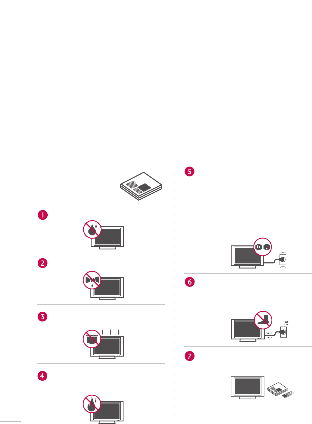
Read these instructions.
Keep these instructions.
Heed all warnings.
Follow all instructions.
Do not use this apparatus near water
Clean only with dry cloth.
Do not block any ventilation openings. Install in
accordance with the manufacturer’s instructions.
Do not install near any heat sources such as
radiators, heat registers, stoves, or other appa-
ratus (including amplifiers)that produce heat.
Do not defeat the safety purpose of the
polarized or grounding-type plug. A polarized
plug has two blades with one wider than the
other. A grounding type plug has two blades
and a third grounding prong, The wide blade
or the third prong are provided for your safe-
ty. If the provided plug does not fit into your
outlet, consult an electrician for replacement
of the obsolete outlet.
Protect the power cord from being walked on
or pinched particularly at plugs, convenience
receptacles, and the point where they exit
from the apparatus.
Only use attachments/accessories specified
by the manufacturer.
2
IMPORTANT SAFETY INSTRUCTIONS
SAFETY INSTRUCTIONS
Important safety instructions shall be provided with each apparatus. This information shall be given in a se-
parate booklet or sheet, or be located before any operating instructions in an instruction for installation for
use and supplied with the apparatus.
This information shall be given in a language acceptable to the country where the apparatus is intended to
be used.
The important safety instructions shall be entitled “Important Safety Instructions”. The following safety
instructions shall be included where applicable, and, when used, shall be verbatim as follows. Additional safe-
ty information may be included by adding statements after the end of the following safety instruction list. At
the manufacturer’s option, a picture or drawing that illustrates the intent of a specific safety instruction may
be placed immediately adjacent to that safety instruction :
Owner Manual
Owner ManualOwner Manual
Owner Manual
Owner Manual
Owner Manual
Owner Manual
Owner Manual
Owner Manual
Owner Manual
Owner Manual
Owner Manual
3
Use only with the cart, stand, tripod, bracket,
or table specified by the manufacturer, or sold
with the apparatus. When a cart is used, use
caution when moving the cart/apparatus
combination to avoid injury from tip-over.
Unplug this apparatus during lightning storms
or when unused for long periods of time.
Refer all servicing to qualified service person-
nel. Servicing is required when the apparatus
has been damaged in any way, such as power-
supply cord or plug is damaged, liquid has
been spilled or objects have fallen into the
apparatus, the apparatus has exposed to rain
or moisture, does not operate normally, or has
been dropped.
CAUTION concerning the Power Cord :
Most appliances recommend they be placed
upon a dedicated circuit; that is, a single out-
let circuit which powers only that appliance
and has no additional outlets or branch cir-
cuits. Check the specification page of this
owner's manual to be certain.
Do not overload wall outlets. Overloaded wall
outlets, loose or damaged wall outlets, exten-
sion cords, frayed power cords, or damaged
or cracked wire insulation are dangerous. Any
of these conditions could result in electric
shock or fire. Periodically examine the cord of
your appliance, and if its appearance indicates
damage or deterioration, unplug it, disconti-
nue use of the appliance, and have the cord
replaced with an exact replacement part by an
authorized servicer. Protect the power cord
from physical or mechanical abuse, such as
being twisted, kinked, pinched, closed in a
door, or walked upon. Pay particular attention
to plugs, wall outlets, and the point where the
cord exits the appliance.
Outdoor Use Marking :
WARNING - To Reduce The Risk Of Fire Or
Electric Shock, Do Not Expose This Appliance
To Rain Or Moisture
Wet Location Marking : Apparatus shall not be
exposed to dripping or splashing and no
objects filled with liquids, such as vases, shall
be placed on or over apparatus.
GROUNDING
Ensure that you connect the earth ground
wire to prevent possible electric shock. If
grounding methods are not possible, have a
qualified electrician install a separate circuit
breaker.
Do not try to ground the unit by connecting
it to telephone wires, lightening rods, or gas
pipes.
DISCONNECTING DEVICE FROM MAINS
Main plug is the disconnecting device. The
plug must remain readily operable.
Owner Manual
Owner Manual
Owner Manual
Owner Manual
Owner Manual
Owner Manual
Owner Manual
Owner Manual
Owner Manual
Power Supply
Short-circuit Breaker

4
CONTENTS
WARNING / CAUTION
. . . . . . . . . . . . . . . . . . . . . . . . . . .
1
SAFETY INSTRUCTIONS
. . . . . . . . . . . . . . . . . . . . . . . . . . 2
FEATURES OF THIS TV . . . . . . . . . . . . . . . . 6
PREPARATION
Accessories . . . . . . . . . . . . . . . . . . . . . . . . . . . . . . 7
Front Panel Controls . . . . . . . . . . . . . . . . . . . . . . 8
Back Panel Information . . . . . . . . . . . . . . . . . . . 10
Attaching the TV to a Wall . . . . . . . . . . . . . . . . . 12
Stand Installation . . . . . . . . . . . . . . . . . . . . . . . . 13
Back Cover for Wire Arrangement . . . . . . . . . . . 14
Desktop Pedestal Installation . . . . . . . . . . . . . . . 16
Vesa Wall Mounting . . . . . . . . . . . . . . . . . . . . . . . 16
Antenna or Cable Connection . . . . . . . . . . . . . . 17
EXTERNAL EQUIPMENT SETUP
HD Receiver Setup . . . . . . . . . . . . . . . . . . . . . . . . . . . . . . . . . . . . . . . . . . 18
DVD Setup . . . . . . . . . . . . . . . . . . . . . . . . . . . . . . . . . . . . . . . . . . . . . . . . . . . . . . 21
VCR Setup . . . . . . . . . . . . . . . . . . . . . . . . . . . . . . . . . . . . . . . . . . . . . . . . . . . . . . 23
Other A/V Source Setup . . . . . . . . . . . . . . . . . . . . . . . . . . . . . . . . . 25
PC Setup . . . . . . . . . . . . . . . . . . . . . . . . . . . . . . . . . . . . . . . . . . . . . . . . . . . . . . . . 26
USB In Setup . . . . . . . . . . . . . . . . . . . . . . . . . . . . . . . . . . . . . . . . . . . . . . . . . . 32
Audio Out Setup . . . . . . . . . . . . . . . . . . . . . . . . . . . . . . . . . . . . . . . . . . . . . 33
WATCHING TV / CHANNEL CONTROL
Remote Control Functions . . . . . . . . . . . . . . . . . .34
Turning on TV . . . . . . . . . . . . . . . . . . . . . . . . . . . 36
Channel Selection . . . . . . . . . . . . . . . . . . . . . . . 37
Volume Adjustment . . . . . . . . . . . . . . . . . . . . . . 38
On-Screen Menus Selection . . . . . . . . . . . . . . . . 39
Channel Setup
- Auto Scan ( Auto Tuning) . . . . . . . . . . . . . . 40
- Add / Delete Channel ( Manual Tuning) . . 41
- Channel Editing . . . . . . . . . . . . . . . . . . . . . . .42
Input List . . . . . . . . . . . . . . . . . . . . . . . . . . . . . . . 43
SimpLink . . . . . . . . . . . . . . . . . . . . . . . . . . . . . . . 44
Input Label . . . . . . . . . . . . . . . . . . . . . . . . . . . . . 46
Entry Modes . . . . . . . . . . . . . . . . . . . . . . . . . . . . 47
Photo List . . . . . . . . . . . . . . . . . . . . . . . . . . . . . . 48
Music List . . . . . . . . . . . . . . . . . . . . . . . . . . . . . . 52
PICTURE CONTROL
Picture Size (Aspect Ratio) Control . . . . . . . . . .54
Preset Picture Settings
- Picture Mode - Preset . . . . . . . . . . . . . . . . 55
- Color Tone - Preset . . . . . . . . . . . . . . . . . . .56
Manual Picture Adjustment
- Picture Mode - User Mode . . . . . . . . . . . . 57
- Color Tone - User Mode. . . . . . . . . . . . . . .58
XD - Picture Improvement Technology . . . . . . . . . . . 59
Advanced - Cinema 3:2 Pulldown Mode . . . . . . 60
Advanced - Black( Darkness) Level . . . . . . . . . . 61
Advanced - TruM . . . . . . . . . . . . . . . . . . . . . . . . . 62
Picture Reset . . . . . . . . . . . . . . . . . . . . . . . . . . . . 63
Image Sticking Minimization( ISM) Method . . . . . . . 64
Low-Power Picture Mode . . . . . . . . . . . . . . . . . . 65
SOUND & LANGUAGE CONTROL
Auto Volume Leveler ( Auto Volume) . . . . . . . . . 66
Preset Sound Settings( Sound Mode) . . . . . . . . 67
Sound Setting Adjustment - User Mode . . . . . . . . 68
Balance . . . . . . . . . . . . . . . . . . . . . . . . . . . . . . . . .70
Stereo / SAP Broadcast Setup . . . . . . . . . . . . . . 71
TV Speakers On/ Off Setup . . . . . . . . . . . . . . . . 72
Audio Language . . . . . . . . . . . . . . . . . . . . . . . . . 73
On-Screen Menus Language Selection . . . . . . . 74
Caption Mode
- Analog Broadcasting System Captions . . . . 75
- Digital Broadcasting System Captions . . .77
- Caption Option . . . . . . . . . . . . . . . . . . . . .78
MEDIAMEDIAMEDIA
HOST HOST HOST
MEDIA
HOST

5
TIME SETTING
Clock Setting
- Auto Clock Setup . . . . . . . . . . . . . . . . . . . 79
- Manual Clock Setup . . . . . . . . . . . . . . . . . .80
Auto On/ Off Time Setting . . . . . . . . . . . . . . . . .81
Sleep Time Setting . . . . . . . . . . . . . . . . . . . . . . . .82
Auto Shut-off Setting . . . . . . . . . . . . . . . . . . . . . 83
PARENTAL CONTROL / RATINGS
Set Password & Lock System . . . . . . . . . . . . . . . 84
Channel Blocking . . . . . . . . . . . . . . . . . . . . . . . . 86
Movie & TV Rating . . . . . . . . . . . . . . . . . . . . . . . 87
External Input Blocking . . . . . . . . . . . . . . . . . . . . 90
Key Lock . . . . . . . . . . . . . . . . . . . . . . . . . . . . . . . 90
APPENDIX
Troubleshooting . . . . . . . . . . . . . . . . . . . . . . . . . .91
Maintenance . . . . . . . . . . . . . . . . . . . . . . . . . . . .93
Product Specifications . . . . . . . . . . . . . . . . . . . . 94
Programming the Remote Control . . . . . . . . . . 96
IR Codes . . . . . . . . . . . . . . . . . . . . . . . . . . . . . . 100
External Control through RS-232C . . . . . . . . . 102

6
FEATURES OF THIS TV
What is a Plasma TV ?
Using plasma is the best way to achieve flat panel
displays with excellent image quality and large screen
sizes that are easily viewable. The Plasma TV can be
thought of as a descendant of the neon lamp and or
a series of fluorescent lamps.
How does it work?
Plasma TV is an array of cells, known as pixels, which
are comprised of three sub-pixels, corresponding to
the colors red, green, and blue. Gas in a plasma state
is used to react with phosphors in each sub-pixel to
produce colored light (red, green, or blue). These
phosphors are the same types used in Cathode Ray
Tube (CRT) devices such as televisions and common
computer monitors.
Plasma TV offers a rich, dynamic display because
each sub-pixel is individually controlled by advanced
electronics to produce over 16 million different col-
ors. This means that you get perfect images that are
easily viewable in a display that is fewer than five
inches thick.
160° - Wide angle range of vision
Your flat panel plasma screen offers an exceptionally
broad viewing angle of over 160 degrees. This means
that the display is clear and visible to viewers any-
where in the room.
Wide Screen
The wide screen offers a theater-like experience in
your own home.
Multimedia
Connect your plasma display to a PC and use it for
conferencing, games, and Internet browsing. The
Picture-in-Picture feature allows you to view your PC
and video images simultaneously.
Versatile
The light weight and thin size makes it easy to install
your plasma display in a variety of locations where
conventional TVs do not fit.
The Plasma TV Manufacturing Process: a few
minute colored dots may be present on the
Plasma TV screen
The Plasma TV is composed of 0.9 to 2.2 million
cells. A few cell defects will normally occur in the
Plasma TV manufacturing process. Several tiny,
minute colored dots visible on the screen should be
acceptable. This also occurs in other Plasma TV
manufacturers' products. The tiny dots appearing
does not mean that this Plasma TV is defective. Thus
a few cell defects are not sufficient cause for the
Plasma TV to be exchanged or returned. Our pro-
duction technology minimizes these cell defects dur-
ing the manufacture and operation of this product.
Cooling Fan Noise (This feature is not available for all models.)
In the same way that a fan is used in a PC computer
to keep the CPU (Central Processing Unit) cool, the
Plasma TV is equipped with cooling fans to cool the
Monitor and improve its reliability. Therefore, a cer-
tain level of noise could occur while the fans are
operating and cooling the Plasma TV.
The fan noise doesn't have any negative effect on
the Plasma TV's efficiency or reliability. The noise
from these fans is normal during the operation of
this product. We hope you understand that a certain
level of noise from the cooling fans is acceptable and
is not sufficient cause for the Plasma TV to be
exchanged or returned.
FOR LCD TV
If the TV feels cold to the touch, there may be a
small “flicker” when it is turned on. This is normal,
there is nothing wrong with TV.
Some minute dot defects may be visible on the
screen, appearing as tiny red, green, or blue spots.
However, they have no adverse effect on the moni-
tor's performance.
Avoid touching the LCD screen or holding your fin-
ger(s) against it for long periods of time. Doing so
may produce some temporary distortion effects on
the screen.
OOnn DDiissppoossaall
a. The fluorescent lamp used in this product con-
tains a small amount of mercury.
b. Do not dispose of this product with general
household waste.
c. Disposal of this product must be carried out in
accordance to the regulations of your local
authority.
PREPARATION
7
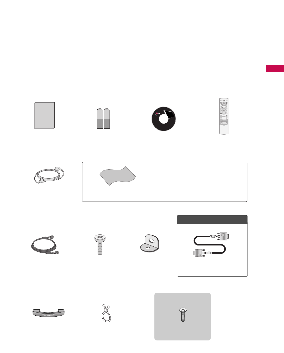
ACCESSORIES
Owner's Manual
1.5V 1.5V
Owner’s Manual Batteries
75ΩRound Cable
Remote Control
Cable Management
2- TV Bracket Bolts 2- TV Brackets,
2- Wall Brackets
Twist Holder
Arrange the wires with the twist holder.
Ensure that the following accessories are included with your plasma display. If an accessory is missing, please
contact the dealer where you purchased the product.
User must use shielded signal interface cables (D-sub 15 pin cable) with ferrite cores to maintain standard
compliance for the product.
APM
CC
AUTO DEMO
M/C EJECT
TV INPUT
TV INPUT
STB
STB
MENU
BRIGHT +
BRIGHT -
TIMER
RATIO
SIMPLINK
BACK
BACK
4-bolts for stand assembly
Refer to p. 13
3322//3377 iinncchheess oonnllyy
■Slightly wipe stained spot on the exterior only with the polishing
cloth for the product exterior if there is stain or fingerprint on
surface of the exterior.
■Do not wipe roughly when removing stain. Please be cautions of
that excessive power may cause scratch or discoloration.
Polishing Cloth
OOppttiioonn EExxttrraass
D-sub 15 pin Cable
Power Cord
CD Manual
LCD TV PLASMA TV
Owner's Manual
http://www.lgusa.com
www.lg.ca
Copyright© 2007 LGE,
All Rights Reserved.
PREPARATION
PREPARATION
8
PREPARATION
FRONT PANEL CONTROLS
■
Here shown may be somewhat different from your TV.
R
Remote Control Sensor Power/Standby Indicator
• illuminates red in standby mode.
• illuminates green when the set is
switched on.
CH
VOL
ENTER
MENU
INPUT
/I
CHANNEL
(EE,DD) Buttons
VOLUME
(FF,GG) Buttons
ENTER Button
MENU Button
INPUT Button
POWER Button
32/37/42LB4D
Intelligent Eye
Adjusts picture
according to the
surrounding con-
ditions.
PREPARATION
9
CH
VOL
ENTER
MENU
INPUT
/I
CHANNEL
(EE,DD) Buttons
VOLUME
(FF,GG) Buttons
ENTER Button
MENU Button
INPUT Button
POWER Button
37/42/47LB5D
Remote Control Sensor Power/Standby Indicator
• illuminates red in standby mode.
• illuminates green when the set is
switched on.
Intelligent Eye
Adjusts picture
according to the
surrounding con-
ditions.
PREPARATION
10
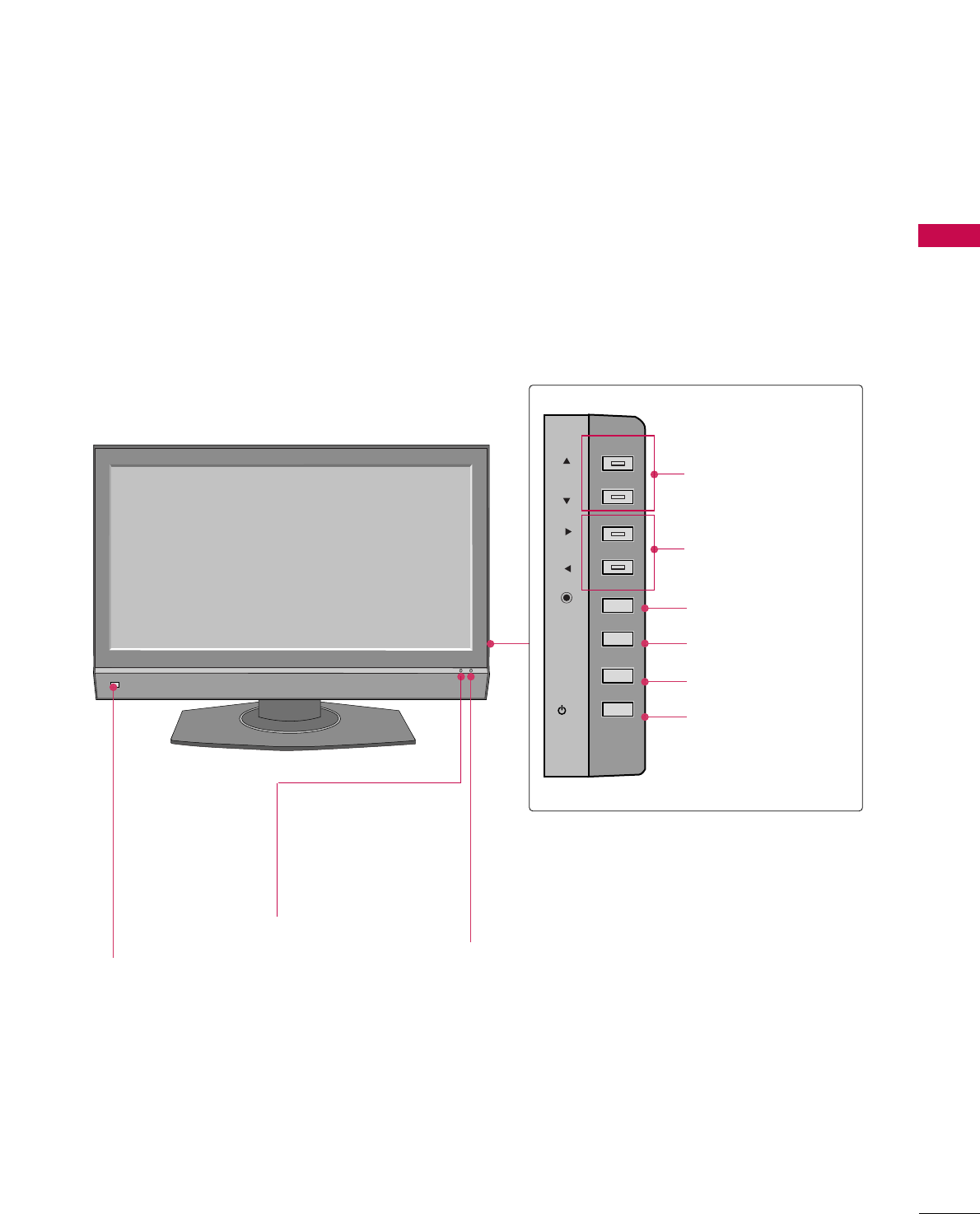
PREPARATION
AV IN 2
L/MONO
R
AUDIO
VIDEO
S-VIDEO
USB IN
AV IN 2
L/MONO
R
AUDIO
VIDEO
USB IN
USB Input
S-VIDEO Input
Connect S-Video out from
an S-VIDEO device.
AUDIO/VIDEO Input
Connect audio/video out-
put from an external device
to these jacks.
AV IN 2V IN 2
L/L/MONOMONO
R
AUDIOAUDIO
VIDEOVIDEO
S-VIDEO
USB INUSB IN
AV IN 2
L/MONO
R
AUDIO
VIDEO
USB IN
BACK PANEL INFORMATION
32/37/42LB4D
USB Input
S-VIDEO Input
Connect S-Video out from an S-
VIDEO device.
AUDIO/VIDEO Input
Connect audio/video output from
an external device to these jacks.
AV IN 2
L/
MONO
R
AUDIO
A
VIDEO
S-VIDEO
USB IN
37/42/47LB5D
AV IN 2
L/MONO
R
AUDIO
VIDEO
S-VIDEO
USB IN
AV IN 2V IN 2
L/L/MONOMONO
R
AUDIOAUDIO
VIDEOVIDEO
USB INUSB IN
32 inch
37/42 inches
■
Here shown may be somewhat different from your TV.
PREPARATION
11
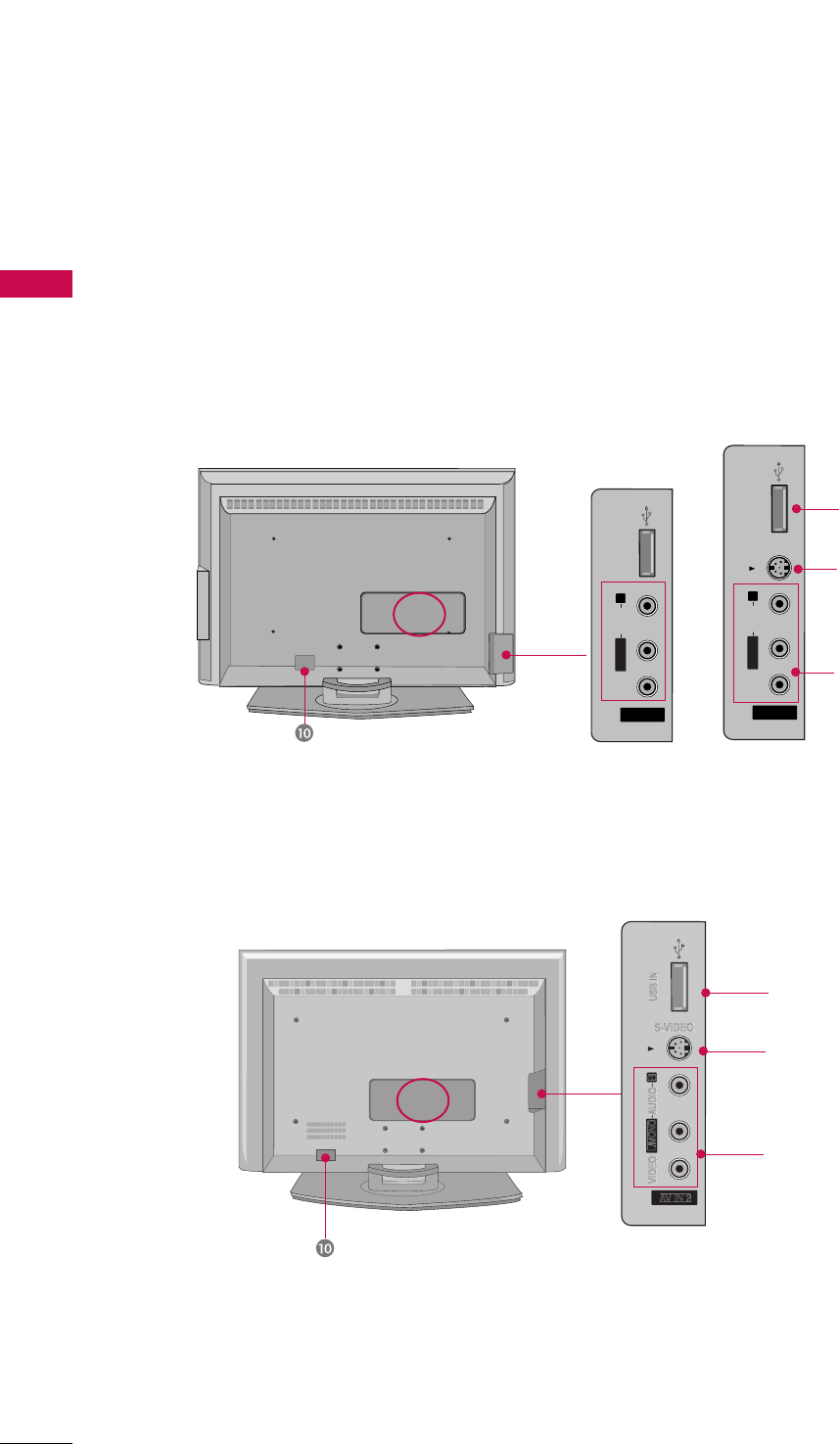
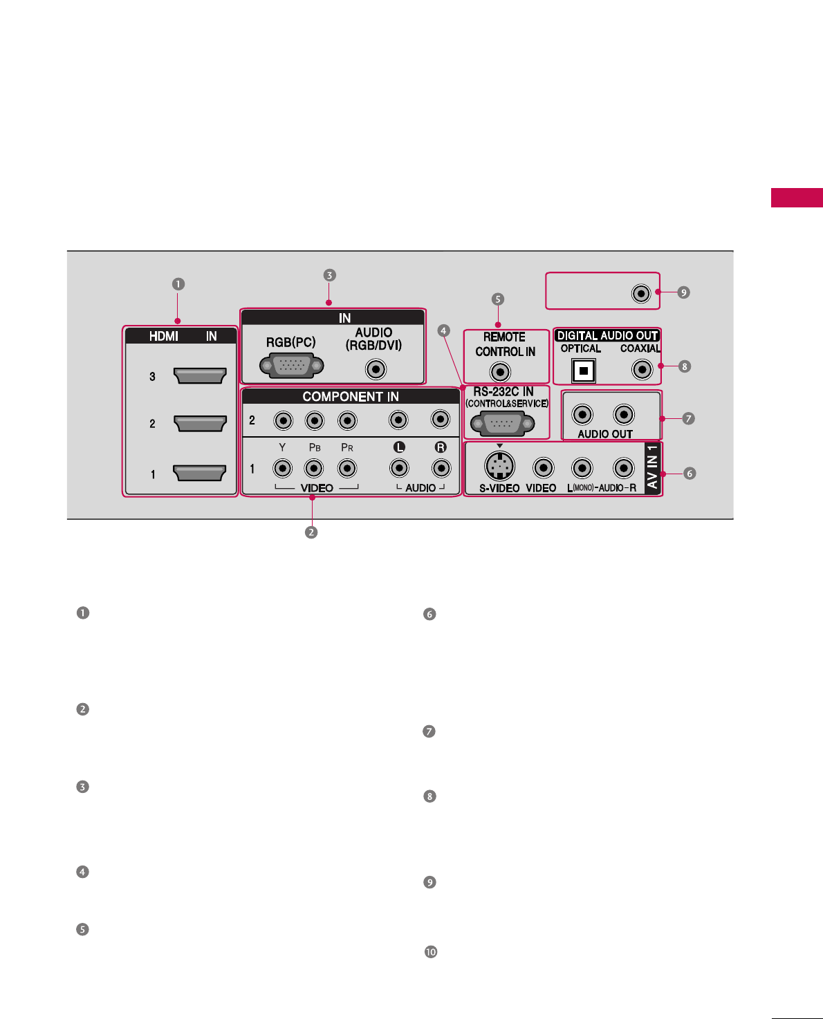
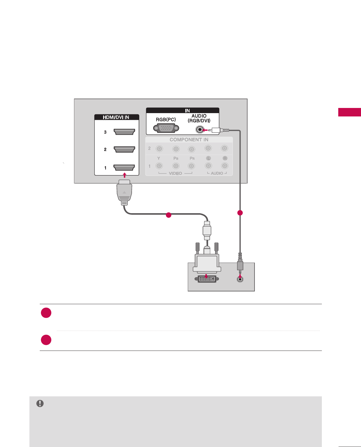
HDMI/DVI IN
Connect a HDMI signal to 1, 2 or 3.
Or DVI (VIDEO)signal to the 1, 2 or 3 port
with a DVI to HDMI cable.
COMPONENT IN
Connect a component video/audio device to
these jacks.
RGB(PC)
AUDIO (RGB/DVI)
Connect the monitor output from a PC to the
appropriate input port.
RS-232C IN (CONTROL & SERVICE) PORT
Connect to the RS-232C port on a PC.
REMOTE CONTROL PORT
Connect your wired remote control.
AV (Audio/Video) IN 1
Connect audio/video output from an external
device to these jacks.
S-VIDEO
Connect S-Video out from an S-VIDEO device.
AUDIO OUT
Connect analog audio to various types of
equipment.
DIGITAL AUDIO OUT
Connect digital audio to various types of
equipment.
Note: In standby mode, these ports do not work.
ANTENNA/CABLE IN
Connect over-the air signals to this jack.
Connect cable signals to this jack.
Power Cord Socket
For operation with AC power.
Caution :
Never attempt to operate the TV on DC power.
AV IN 2
L/MONO
R
AUDIO
VIDEO
S-VIDEO
USB IN
RGB
/DVI
ANTENNA/
CABLE IN
PREPARATION
12
PREPARATION
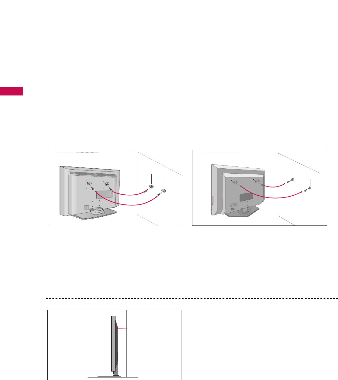
ATTACHING THE TV TO A WALL
32/37/42LB4D 37/42/47LB5D
We recommend that you set up the TV close to a wall so it cannot fall over if pushed backwards.
Additionally, we recommend that the TV be attached to a wall so it cannot be pulled in a forward direction,
potentially causing injury or damaging the product.
Caution: Please make sure that children don’t climb on or hang from the TV.
■Insert the eye-bolts (or TV brackets and bolts) to tighten the product to the wall as shown in the picture.
*Insert the eye-bolts and tighten them securely in the upper holes.
Secure the wall brackets with the bolts (not provided as parts of the product, must purchase separately ) to
the wall. Match the height of the bracket that is mounted on the wall to the holes in the product.
Ensure the eye-bolts or brackets are tightened securely.
■Use a sturdy rope (not provided as parts of the
product, must purchase separately) to tie the
product. It is safer to tie the rope so it becomes
horizontal between the wall and the product.
■
Here shown may be somewhat different from your TV.
PREPARATION
13
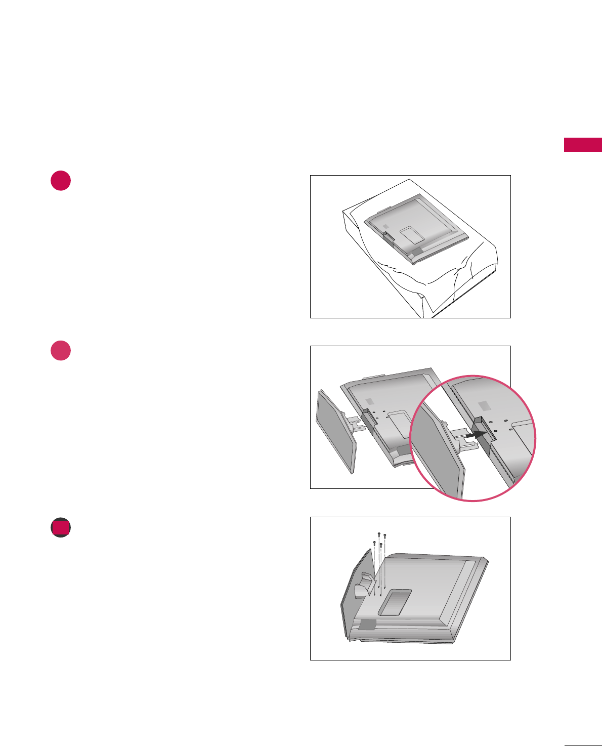
STAND INSTALLATION (Only 32/37 inches models)
1
2
3
Carefully place the product screen side down on
a cushioned surface that will protect product and
screen from damage.
Assemble the product stand with the product as
shown.
Install the 4 bolts securely, in the back of the
product in the holes provided.
PREPARATION
14
PREPARATION
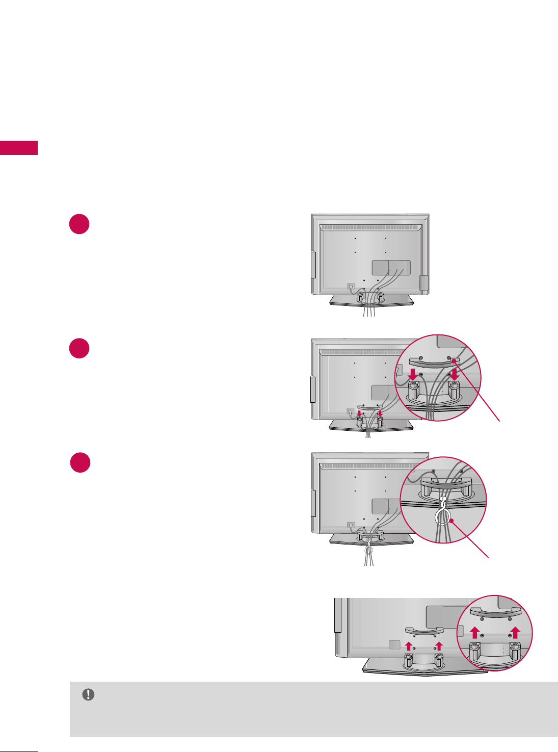
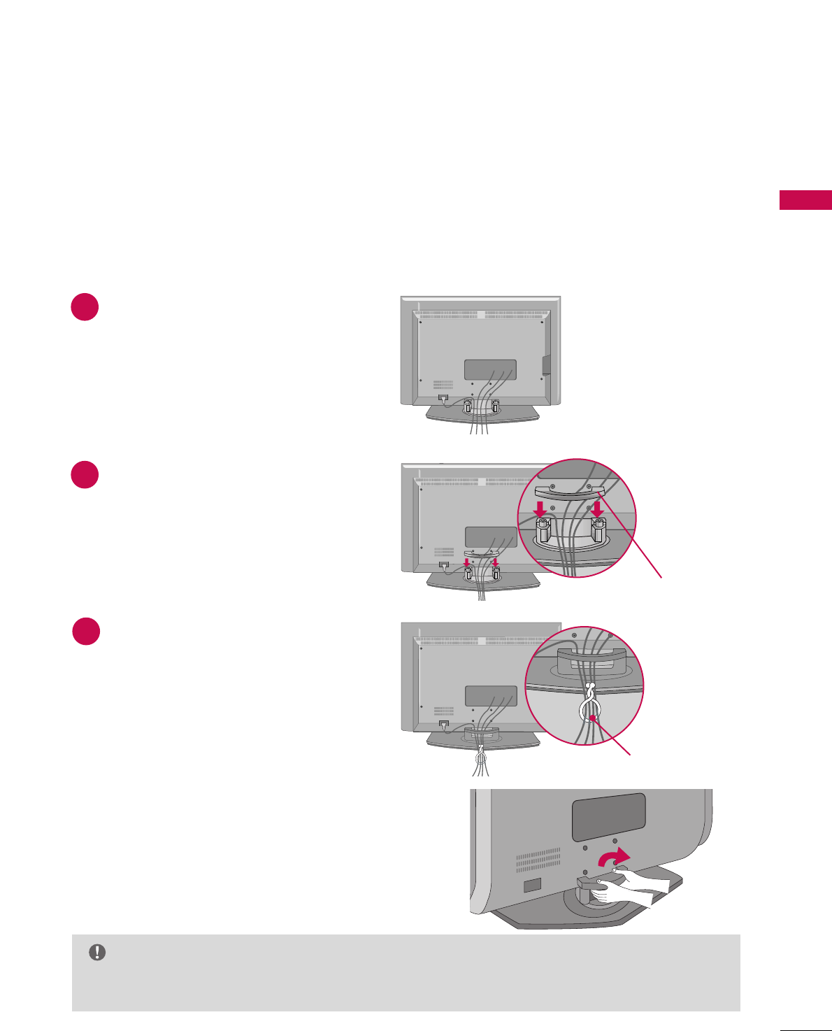
BACK COVER FOR WIRE ARRANGEMENT
32/37/42LB4D
Connect the cables as necessary.
To connect an additional equipment, see the
EExxtteerrnnaall eeqquuiippmmeennttCCoonnnneeccttiioonnss section.
Install the CCAABBLLEE MMAANNAAGGEEMMEENNTTas shown.
Bundle the cables using the supplied twist
holder.
Hold the CCAABBLLEE MMAANNAAGGEEMMEENNTTwith both
hands and pull it upward.
NOTE
GG Do not hold the CABLE MANAGEMENT when moving the product.
- If the product is dropped, you may be injured or the product may be broken.
How to remove the cable management
CABLE MANAGEMENT
TWIST HOLDER
1
2
3
■
Here shown may be somewhat different from your TV.
PREPARATION
15
37/42/47LB5D
Connect the cables as necessary.
To connect an additional equipment, see the
EExxtteerrnnaall eeqquuiippmmeennttCCoonnnneeccttiioonnss section.
Install the CCAABBLLEE MMAANNAAGGEEMMEENNTTas shown.
Bundle the cables using the supplied twist
holder.
Hold the CCAABBLLEE MMAANNAAGGEEMMEENNTTwith both
hands and pull it upward.
NOTE
GG Do not hold the CABLE MANAGEMENT when moving the product.
- If the product is dropped, you may be injured or the product may be broken.
How to remove the cable management
CABLE MANAGEMENT
TWIST HOLDER
1
2
3
■
Here shown may be somewhat different from your TV.
PREPARATION
16
PREPARATION
DESKTOP PEDESTAL INSTALLATION
For proper ventilation, allow a clearance of 4 in. on each side and the top, 2.36 in. on the bottom, and 4 in.
from the wall.
4 inches
4 inches
R
4 inches
4 inches
37/42/47LB5D
32/37/42LB4D
4 inches 4 inches
4 inches 4 inches
VESA WALL MOUNTING
This product accepts a VESA-compliant mounting interface pad. (optional)
There 4 threaded holes are available for attaching the bracket.
GGScrew length needed depends on the wall mount used. For further information, refer to the VESA
Wall Mounting Instruction Guide.
NOTE
37/42/47LB5D
32/37/42LB4D
AV IN 2
L/ MONO
R
AUDIO
VIDEO
S-VIDEO
USB IN
AV IN 2
L/ MONO
R
AUDIO
VIDEO
USB IN
400mm
(32 inches only: 100mm)
400mm
600mm
(32 inches only: 200mm) 600mm
PREPARATION
17
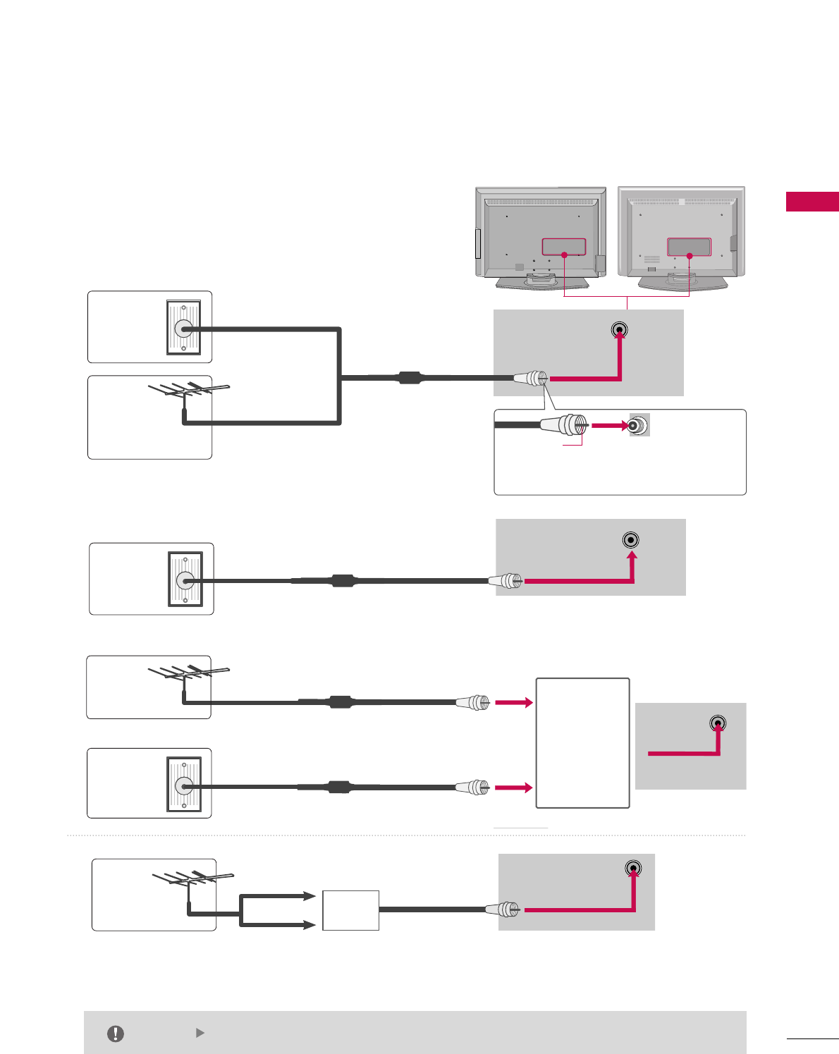
1. Antenna (analog or digital)
Wall Antenna Socket or Outdoor Antenna without a Cable Box
Connections. For optimum picture quality, adjust antenna direc-
tion if needed.
2. Cable
ANTENNA/
CABLE IN
ANTENNA/
CABLE IN
Wall
Antenna
Socket
Outdoor
Antenna
(VHF, UHF)
Cable TV
Wall Jack
Multi-family Dwellings/Apartments
(Connect to wall antenna socket)
RF Coaxial Wire (75 ohm)
RF Coaxial Wire (75 ohm)
Single-family Dwellings /Houses
(Connect to wall jack for outdoor antenna)
Be careful not to bend the bronze wire
when connecting the antenna.
Copper Wire
The TV will let you know when the analog, cable, and digital channel scans are complete.
NOTE
ANTENNA/
CABLE IN
■To improve the picture quality in a poor signal area, please purchase a signal amplifier and install properly.
■If the antenna needs to be split for two TV’s, install a 2-Way Signal Splitter.
■If the antenna is not installed properly, contact your dealer for assistance.
Antenna
UHF
Signal
Amplifier
VHF
3. Using both cable and antenna
Cable TV
Wall Jack
Antenna
RF Coaxial Wire (75 ohm)
RF Coaxial Wire (75 ohm)
Diplexer
(Signal
Combinner)
ANTENNA/
CABLE IN
ANTENNA OR CABLE CONNECTION
AV IN 2
L/ MONO
R
AUDIO
VIDEO
S-VIDEO
USB IN
AV IN 2
L/ MONO
R
AUDIO
VIDEO
USB IN
HD RECEIVER SETUP
This TV can receive Digital Over-the-air/Cable signals without an external digital set-top box. However, if you
do receive digital signals from a digital set-top box or other digital external device, refer to the figure as
shown below.
This TV supports HDCP (High-bandwidth Digital Contents Protection)protocol for Digital Contents
(480p,720p,1080i).
(DVI)
Y L RPBPR
(DVI)
RGB
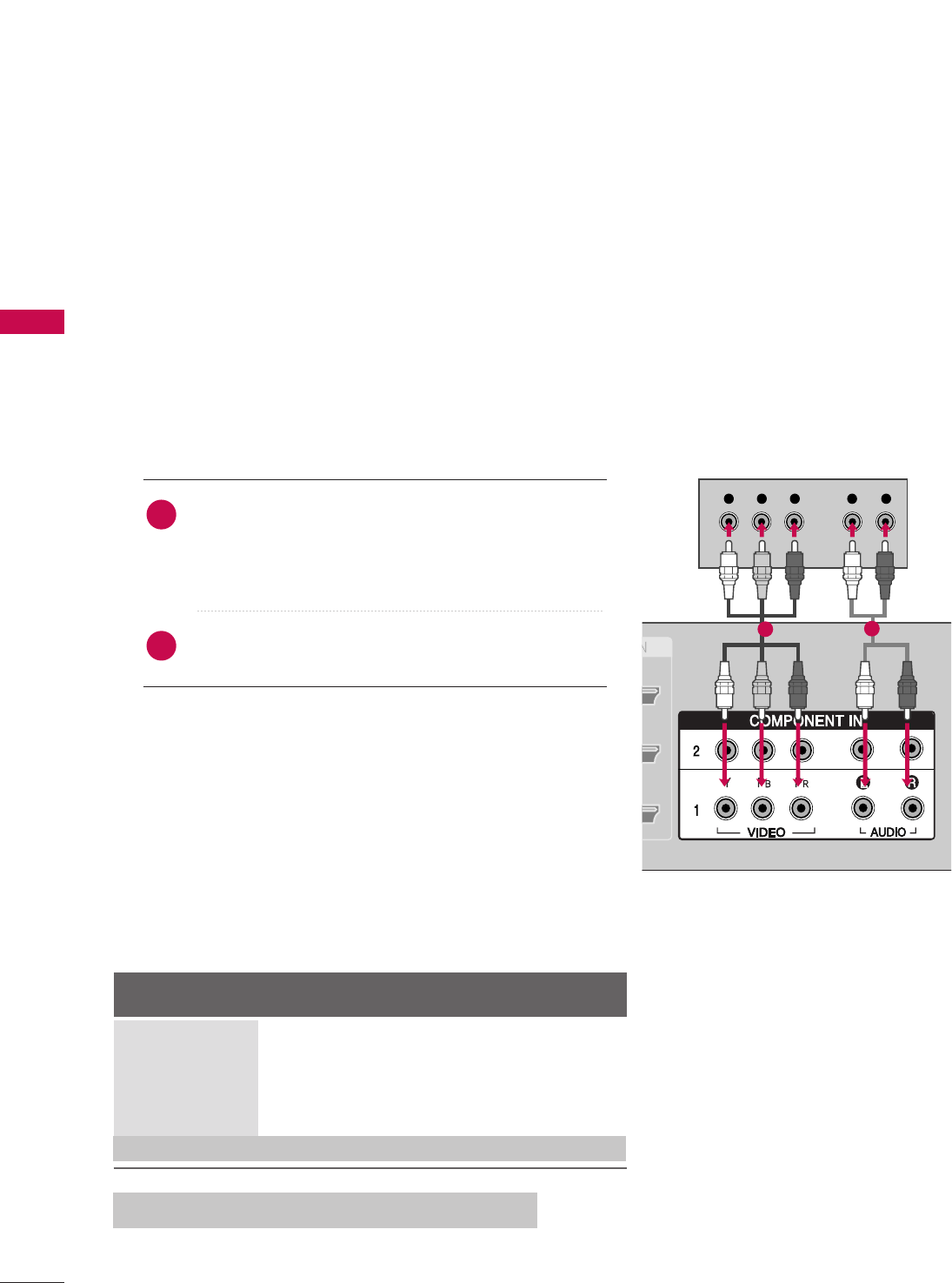
When connecting Component cable
1. How to connect
Connect the video outputs (Y, PB, PR)of the digital set
top box to the CCOOMMPPOONNEENNTT IINN VVIIDDEEOO 11jacks on
the set. Match the jack colors
(Y = green, PB= blue, and PR= red).
Connect the audio output of the digital set-top box to
the CCOOMMPPOONNEENNTT IINN AAUUDDIIOO 11jacks on the set.
2. How to use
■Turn on the digital set-top box.
(Refer to the owner’s manual for the digital set-top box.)
■Select CCOOMMPPOONNEENNTT 11input source with using the IINNPPUUTT
button on the remote control.
■If connected to CCOOMMPPOONNEENNTT IINN 22input, select CCOOMMPPOO--
NNEENNTT 22input source.
Signal Component 1/2
Yes
Yes
Yes
Yes
Yes
HDMI/DVI1, 2 or 3
No
Yes
Yes
Yes
Yes
2
1
EXTERNAL EQUIPMENT SETUP
18
12
480i
480p
720p
108 0 i
108 0 p
108 0 p
* Only 37/42/47LB5D models
EXTERNAL EQUIPMENT SETUP
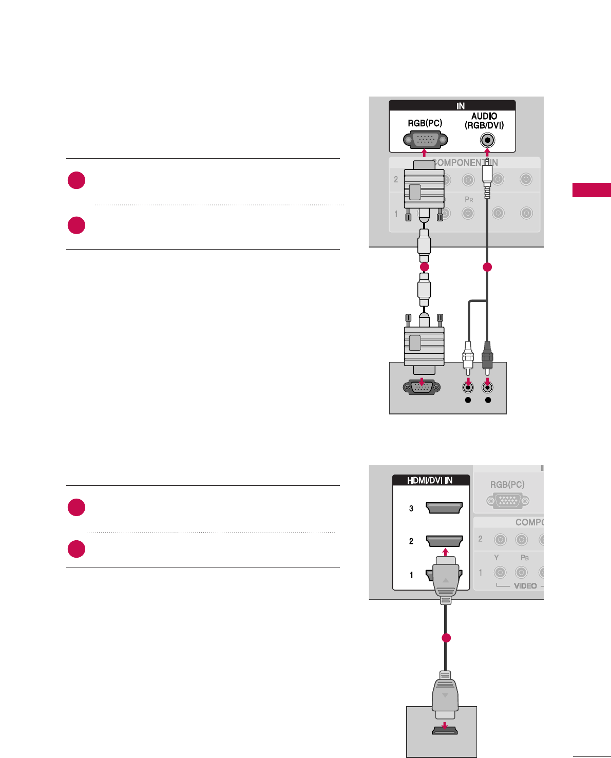
When connecting D-sub 15pin cable
(DVI)
(DVI)
RGB
L R
RGB OUTPUT
(DVI)
(DVI)VI)
HDMI-DTV OUTPUT
RGB
Connect the RGB output of the digital set-top box to
the RRGGBB ((PPCC))jack on the set.
Connect the audio outputs of the set-top box to the
AAUUDDIIOO ((RRGGBB//DDVVII))jack on the set.
1. How to connect
2. How to use
■Turn on the PC and the set.
■Select RRGGBB--PPCCinput source with using the IINNPPUUTTbutton
on the remote control.
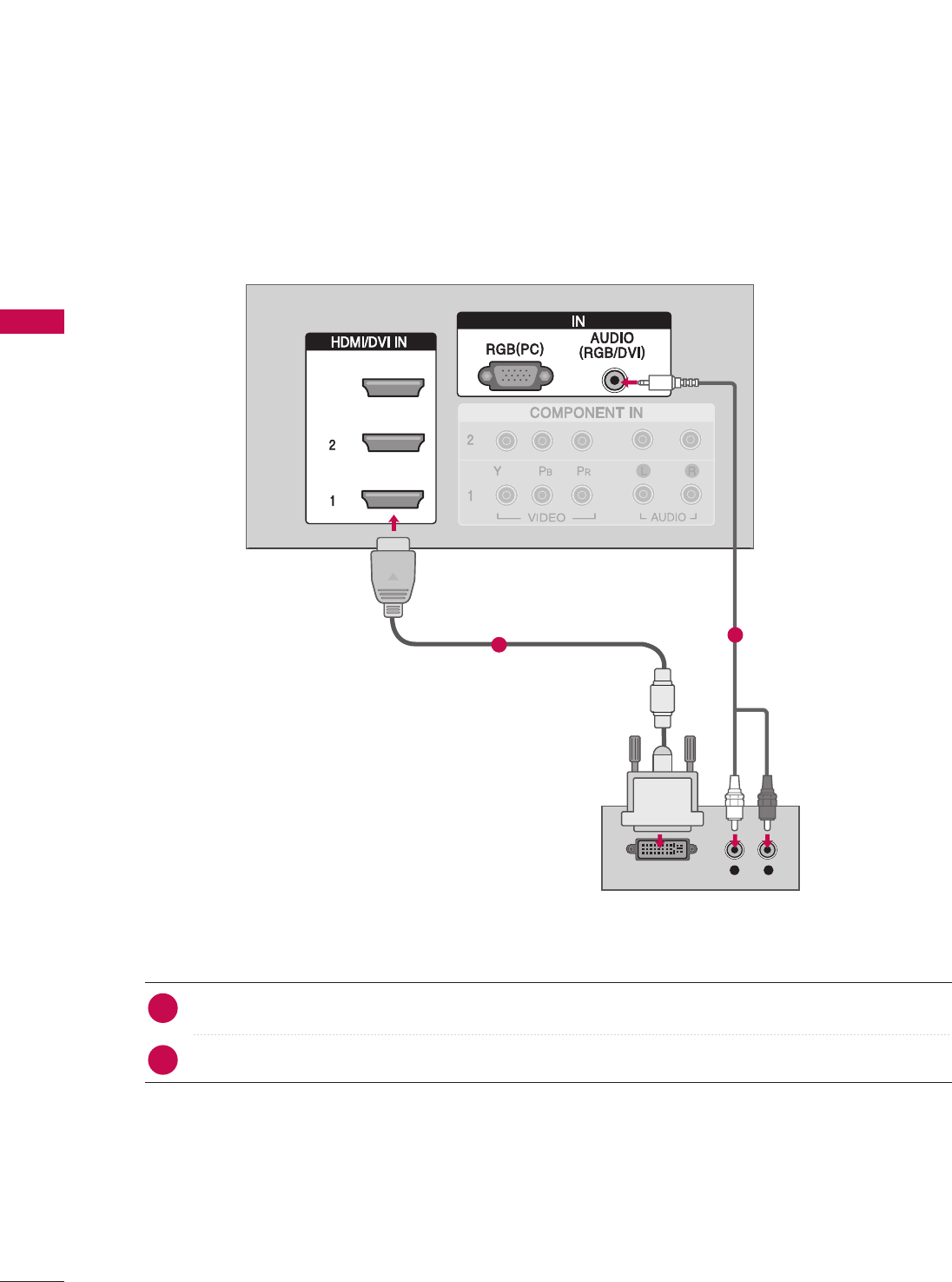
When connecting HDMI cable
Connect the digital set-top box to HHDDMMII//DDVVII IINN11,
22 or 33 jack on the set.
No separated audio connection is necessary.
1. How to connect
2. How to use
■Turn on the digital set-top box.
(Refer to the owner’s manual for the digital set-top box.)
■Select HHDDMMII11,HHDDMMII22 or HHDDMMII33input source with using
the IINNPPUUTTbutton on the remote control.
■If the digital set-top box player does not support Auto HDMI,
you need to set the output resolution appropriately.
2
1
2
1
EXTERNAL EQUIPMENT SETUP
19
12
1
EXTERNAL EQUIPMENT SETUP
20
EXTERNAL EQUIPMENT SETUP
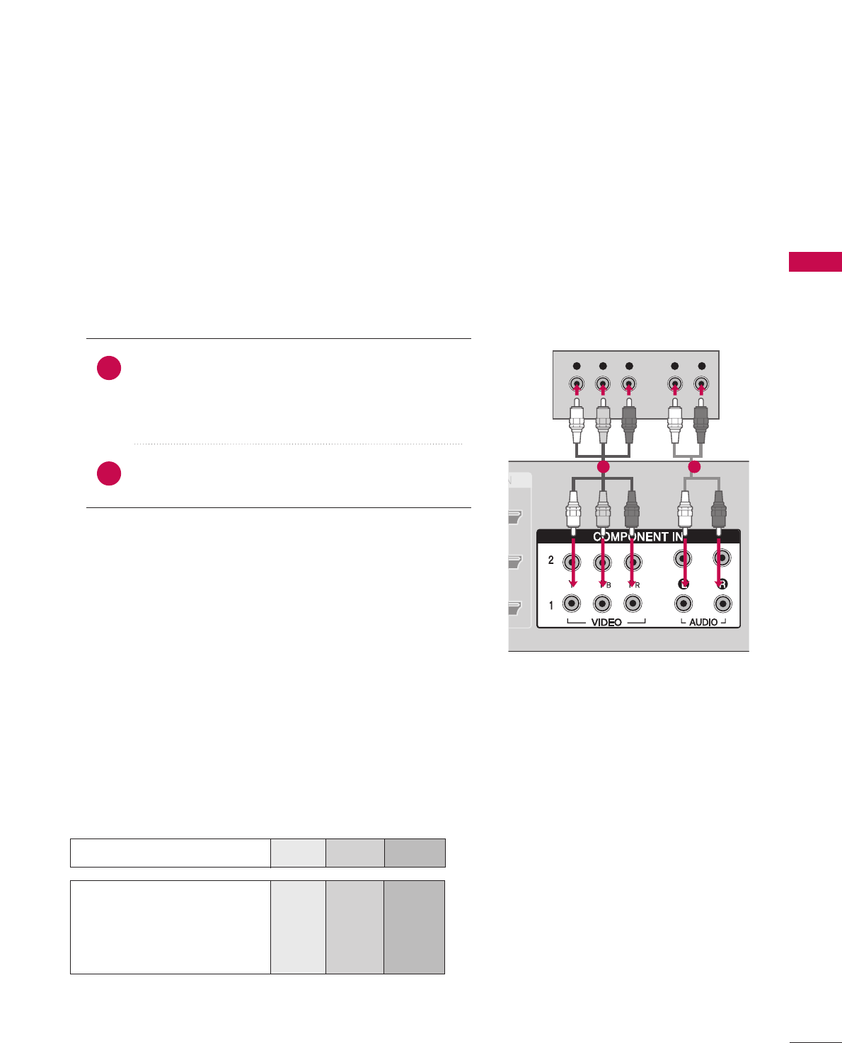
When connecting HDMI to DVI cable
L R
DVI-DTV OUTPUT
RGB
RGB
3
Connect the DVI output of the digital set-top box to the HHDDMMII//DDVVII IINN11, 22 or 33 jack on the set.
Connect the audio output of the digital set-top box to the AAUUDDIIOO((RRGGBB//DDVVII))jack on the set.
1. How to connect
■Turn on the digital set-top box. (Refer to the owner’s manual for the digital set-top box.)
■Select HHDDMMII11,HHDDMMII22 or HHDDMMII33input source with using the IINNPPUUTTbutton on the remote control.
2. How to use
2
1
12
EXTERNAL EQUIPMENT SETUP
21
DVD SETUP
Component Input ports
To get better picture quality, connect a DVD player to the component input ports as shown below.
Component ports on the TV
YP
BPR
Video output ports
on DVD player
Y
Y
Y
Y
PB
Pb
B-Y
Cb
PR
Pr
R-Y
Cr
Y L RPBPR
When connecting Component cable
Connect the video outputs (Y, PB, PR)of the DVD to
the CCOOMMPPOONNEENNTT IINN VVIIDDEEOO11jacks on the set.
Match the jack colors
(Y = green, PB= blue, and PR= red).
Connect the audio outputs of the DVD to the
CCOOMMPPOONNEENNTT IINN AAUUDDIIOO11jacks on the set.
1. How to connect
2. How to use
■Turn on the DVD player, insert a DVD.
■Select CCOOMMPPOONNEENNTT 11input source with using the
IINNPPUUTTbutton on the remote control.
■If connected to CCOOMMPPOONNEENNTT IINN 22input, select CCOOMM--
PPOONNEENNTT 22input source.
■Refer to the DVD player's manual for operating instruc-
tions.
2
1
1 2
When connecting with an S-Video cable
HDMI-DVD OUTPUT
L R
S-VIDEO
AUDIO
Connect the S-VIDEO output of the DVD to the
SS--VVIIDDEEOOinput on the set.
Connect the audio outputs of the DVD to the AAUUDDIIOO
input jacks on the set.
1. How to connect
2. How to use
■Turn on the DVD player, insert a DVD.
■Select AAVV11input source with using the IINNPPUUTTbutton on
the remote control.
■If connected to AAVV IINN 22, select AAVV22input source.
■Refer to the DVD player's manual for operating instructions.
When connecting HDMI cable
Connect the HDMI output of the DVD to the
HHDDMMII//DDVVII IINN11, 22 or 33jack on the set.
No separated audio connection is necessary.
1. How to connect
2. How to use
■Select HHDDMMII11,HHDDMMII22 or HHDDMMII33input source with using
the IINNPPUUTTbutton on the remote control.
■Refer to the DVD player's manual for operating instruc-
tions.
■If the DVD does not support Auto HDMI, you need to set
the output resolution appropriately.
2
1
2
1
22
EXTERNAL EQUIPMENT SETUP
EXTERNAL EQUIPMENT SETUP
EXTERNAL EQUIPMENT SETUP
1 2
1
VCR SETUP
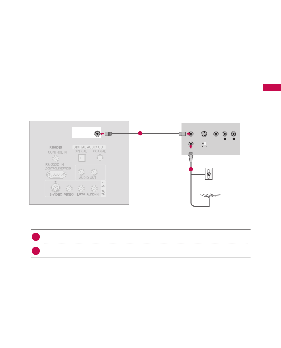
When connecting with an antenna
■To avoid picture noise (interference), leave an adequate distance between the VCR and TV
■Use the ISM feature in the Option menu to avoid having a fixed image remain on the screen for a long pe-
riod of time. If the 4:3 picture format is used; the fixed images on the sides of the screen may remain visible
on the screen.
L R
S-VIDEO VIDEO
OUTPUT
SWITCH
ANT IN
ANT OUT
ANTENNA/ANTENNA/
CABLE INCABLE IN
Wall Jack
Antenna
Connect the RF antenna out socket of the VCR to the AAnntteennnnaasocket on the set.
Connect the antenna cable to the RF antenna in socket of the VCR.
1. How to connect
■Set VCR output switch to 3 or 4 and then tune TV to the same channel number.
■Insert a video tape into the VCR and press PLAY on the VCR. (Refer to the VCR owner’s manual.)
2. How to use
2
1
23
EXTERNAL EQUIPMENT SETUP
1
2
EXTERNAL EQUIPMENT SETUP
24
EXTERNAL EQUIPMENT SETUP
When connecting with a RCA cable
Do not connect to both Video
and S-Video at the same time.
CAUTION
L R S-VIDEOVIDEO
OUTPUT
SWITCH
ANT IN
ANT OUT
ANTENNA/
CABLE IN
L R
S-VIDEO VIDEO
OUTPUT
SWITCH
ANT IN
ANT OUT
ANTENNA/
CABLE IN
Connect the AAUUDDIIOO/VVIIDDEEOOjacks between TV and
VCR. Match the jack colors(Video = yellow, Audio Left =
white,and Audio Right = red)
1. How to connect
2. How to use
■Insert a video tape into the VCR and press PLAY on the
VCR. (Refer to the VCR owner’s manual.)
■Select AAVV11input source with using the IINNPPUUTTbutton on
the remote control.
■If connected to AAVV IINN 22, select AAVV22input source.
If you have a mono VCR, con-
nect the audio cable from the
VCR to the AAUUDDIIOO
LL//MMOONNOOjack of the set.
NOTE
When connecting with an S-Video cable
Connect the S-VIDEO output of the VCR to the SS--
VVIIDDEEOOinput on the set. The picture quality is
improved; compared to normal composite (RCA cable)
input.
Connect the audio outputs of the VCR to the AAUUDDIIOO
input jacks on the set.
1. How to connect
2. How to use
■Insert a video tape into the VCR and press PLAY on the VCR.
(Refer to the VCR owner’s manual.)
■Select AAVV11input source with using the IINNPPUUTTbutton on the
remote control.
■If connected to AAVV IINN 22, select AAVV22input source.
1
2
1
1
12
EXTERNAL EQUIPMENT SETUP
25
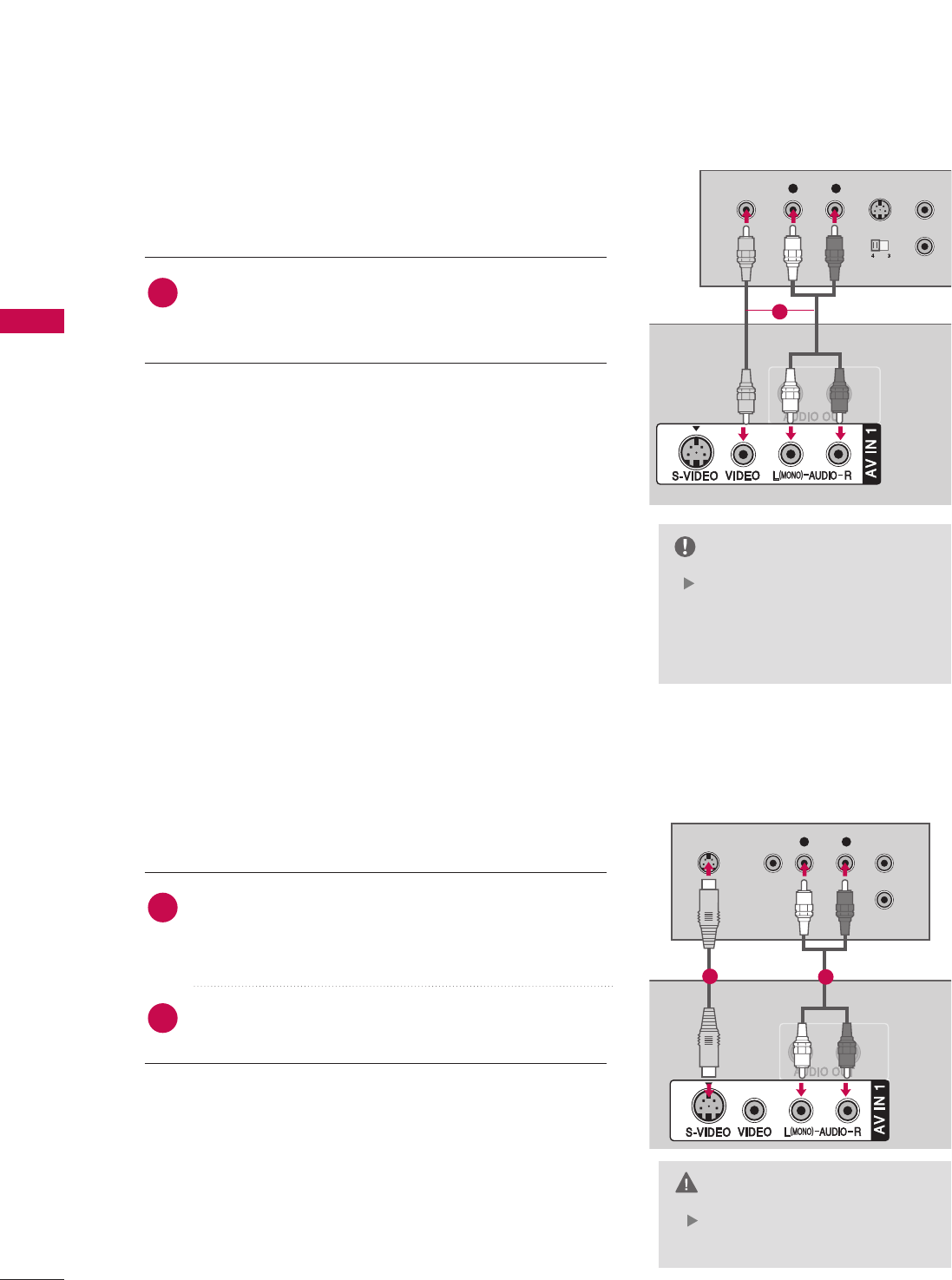
OTHER A/V SOURCE SETUP
Camcorder
Video Game Set
Connect the AAUUDDIIOO/VVIIDDEEOOjacks between TV and
external equipment. Match the jack colors
.
(Video = yellow, Audio Left = white, and Audio Right = red)
1. How to connect
2. How to use
■Select AAVV11input source with using the IINNPPUUTTbutton on
the remote control.
■If connected to AAVV IINN 22input, select AAVV22input source.
■Operate the corresponding external equipment.
1
AV IN 2
L/
MONO
R
AUDIO
A
VIDEO
S-VIDEO
USB IN
L R
VIDEO
AV IN 2
L/
MONO
R
AUDIO
A
VIDEO
USB IN
L R
VIDEO
1
Camcorder
Video Game Set
32 inches 37/42/47 inches
1
EXTERNAL EQUIPMENT SETUP
26
EXTERNAL EQUIPMENT SETUP
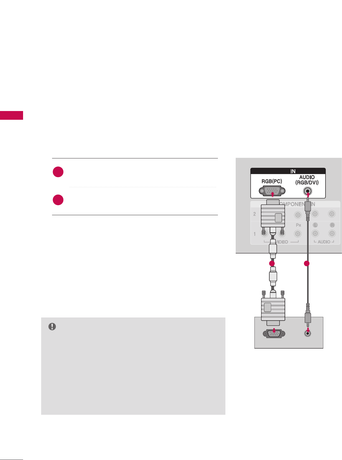
PC SETUP
This TV provides Plug and Play capability, meaning that the PC adjusts automatically to the TV's settings.
GGCheck the image on your TV. There may be noise associated
with the resolution, vertical pattern, contrast or brightness in
PC mode. If noise is present, change the PC output to another
resolution, change the refresh rate to another rate or adjust
the brightness and contrast on the VIDEO menu until the
picture is clear. If the refresh rate of the PC graphic card can
not be changed, change the PC graphic card or consult the
manufacturer of the PC graphic card.
NOTE
RGBRGB
RGB OUTPUT AUDIO
RGB
When connecting D-sub 15 pin cable
Connect the RGB output of the PC to the RRGGBB
((PPCC)) jack on the set.
Connect the PC audio output to the AAUUDDIIOO
((RRGGBB//DDVVII))jack on the set.
1. How to connect
2. How to use
■Turn on the PC and the set.
■Select RRGGBB--PPCCinput source with using the IINNPPUUTTbutton
on the remote control.
2
1
1 2
EXTERNAL EQUIPMENT SETUP
27
When connecting HDMI to DVI cable
GGIf the PC has a DVI output and no HDMI output, a separated audio connection is necessary.
GGIf the PC does not support Auto DVI, you need to set the output resolution appropriately. To get the
best picture quality, adjust the output resolution of PC graphics card's output resolution to 1360x768,
60Hz.(37/42/47LB5D models: 1920x1080, 60Hz)
NOTE
RGB
DVI-PC OUTPUT AUDIO
RGBRGB
Connect the DVI output of the PC to the HHDDMMII//DDVVII IINN11, 22 ou 33 jack on the set.
(Use the HDMI to DVI cable)
Connect the PC audio output to the AAUUDDIIOO((RRGGBB//DDVVII))jack on the set.
1. How to connect
■Turn on the PC and the set
■Select HHDDMMII11,HHDDMMII22 or HHDDMMII33input source with using the IINNPPUUTTbutton on the remote control.
2. How to use
2
1
12

EXTERNAL EQUIPMENT SETUP
28
EXTERNAL EQUIPMENT SETUP
GGDepending on the graphics card, DOS mode may
not work if a HDMI to DVI Cable is in use.
GGCheck the image on your TV. There may be noise
associated with the resolution, vertical pattern,
contrast or brightness in PC mode. If noise is
present, change the PC output to another resolu-
tion, change the refresh rate to another rate or
adjust the brightness and contrast on the PIC-
TURE menu until the picture is clear. If the refresh
rate of the PC graphic card can not be changed,
change the PC graphic card or consult the manu-
facturer of the PC graphic card.
GGAvoid keeping a fixed image on the screen for a
long period of time. The fixed image may become
permanently imprinted on the screen.
GGThe synchronization input form for Horizontal and
Vertical frequencies is separate.
NOTES
EXTERNAL EQUIPMENT SETUP
29
Supported Display Specifications (RGB/HDMI-PC)
Horizontal Vertical
Frequency(KHz)Frequency(Hz)
31.468 70.09
31.469 70.08
31.469 59.94
37.861 72.80
37.500 75.00
35.156 56.25
37.879 60.31
48.077 72.18
46.875 75.00
48.363 60.00
56.476 70.06
60.023 75.02
47.776 59.870
60.289 74.893
47.712 60.015
60.981 60.020
79.976 75.025
75.00 60.00
67.50 60.00
Resolution
720x400
1360x768
640x350
* RGB-PC mode only: 1280x768(H-60.289, V-74.893)
640x480
800x600
1024x768
Supported Display Specifications (HDMI-DTV)
Horizontal Vertical
Frequency(KHz)Frequency(Hz)
31.47 60.00
31.47 59.94
45.00 60.00
44.96 59.94
33.75 60.00
33.72 59.94
67.50 60.00
67.432 59.939
27.00 24.00
26.97 23.94
33.75 30.00
33.71 29.97
Resolution
720x480
1280x720
1920x1080
1280x1024
1600x1200
1920x1080
1280x768
1280x768 Supported Display Specifications (Y, CB /PB,C
R /PR)
Horizontal Vertical
Frequency(KHz)Frequency(Hz)
15.73 60.00
15.73 59.94
31.47 59.94
31.47 60.00
45.00 60.00
44.96 59.94
33.75 60.00
37.72 59.94
67.50 60.00
67.432 59.939
27.00 24.00
26.97 23.94
33.75 30.00
33.71 29.97
Resolution
1280x720
1920x1080
720x480
EXTERNAL EQUIPMENT SETUP
30
EXTERNAL EQUIPMENT SETUP
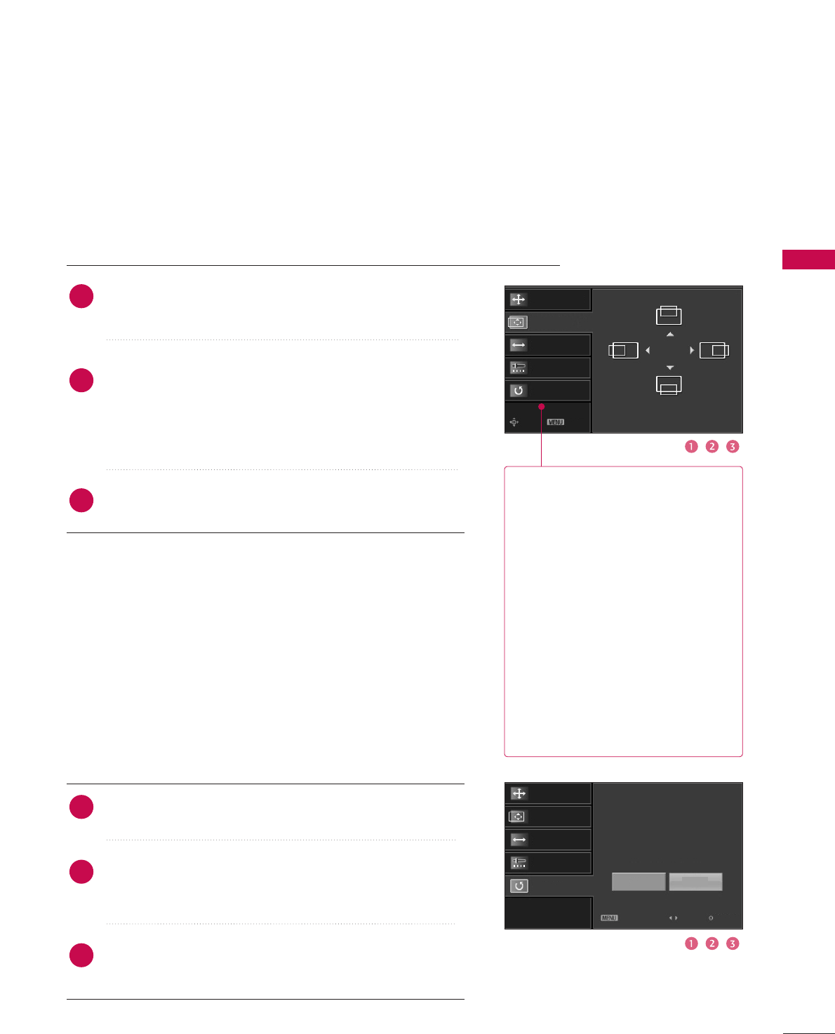
Screen Setup for PC mode
Overview
When the RGB input, of the set is connected to a PC Output, Select
RGB-PC with using the IINNPPUUTTbutton on the remote control.
When you change the resolution, select the proper resolution in
present input to see the best picture appearance.
Picture Mode
Color Temperature
XD
Advanced
Aspect Ratio
Picture Reset
Screen GSelection ( Gor ) leads you to
the screen adjustment menu.
Picture Mode : User1
Color Temperature : Cool
XD
Advanced
Aspect Ratio : 16:9
Picture Reset
Screen
Press the MMEENNUUbutton and then use DDor EEbutton
to select the PPIICCTTUURREEmenu.
Press the GG button and then use DDor EEbutton to
select SSccrreeeenn.
Press the GG button to enter the screen adjustment
menu.
2
3
1
EXTERNAL EQUIPMENT SETUP
31
Resolution
Position GG
Size
Phase
Reset
Move Prev
Resolution
Position
Size
Phase
Reset GG
Initialize Settings.
Yes No
Prev Select OK
RReessoolluuttiioonn XGA(1024, 1280, 1360) isn’t
distinguished because of having
the same H/V Sync Time.
This function is you to select the
Default Sync Time.
PPoossiittiioonnThis function is to adjust picture
to left/right and up/down as you
prefer.
SSiizzeeThis function is to minimize any
vertical bars or stripes visible on
the screen background. And the
horizontal screen size will also
change.
PPhhaasseeThis function allows you to
remove any horizontal noise and
clear or sharpen the image of char-
acters.
Use DDor EEbutton to select RReessoolluuttiioonn, PPoossiittiioonn, SSiizzee,
or PPhhaassee.
Press the EENNTTEERRbutton and then use DD / EEor FF / GG
button to make appropriate adjustments.
■The PPhhaasseeadjustment range is --1166~++1166.
■The SSiizzeeadjustment range is --3300~++3300.
Press the EENNTTEERRbutton.
Adjustment for screen Resolution, Position, Size, Phase, Reset
Use DDor EEbutton to select RReesseett.
Press the EENNTTEERR button and then use FFor GGbutton to
select YYeess.
Press the EENNTTEERRbutton.
Initializing (Reset to original factory values)
2
3
1
2
3
1
To initialize the adjusted values.
EXTERNAL EQUIPMENT SETUP
32
EXTERNAL EQUIPMENT SETUP
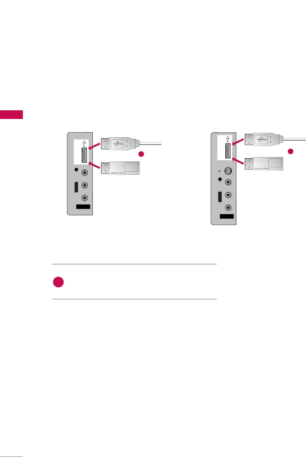
USB IN SETUP
The TV has a special signal output capability which allows you to hook up the second TV or monitor.
AV IN 2V IN 2
L/L/MONOMONO
R
AUDIOAUDIO
VIDEOVIDEO
S-VIDEO
USB INUSB IN
AV IN 2
L/MONO
R
AUDIO
VIDEO
USB IN
Connect the USB device to the UUSSBB IINN jacks on the
side of TV.
1. How to connect
1
2. How to use
■After connecting the UUSSBB IINN jacks, you use the
function. (GGpp..4477)
MEDIAMEDIA
HOST HOST
MEDIAMEDIA
HOST HOST
1
AV IN 2
L/MONO
R
AUDIO
VIDEO
S-VIDEO
USB IN
AV IN 2V IN 2
L/L/MONOMONO
R
AUDIOAUDIO
VIDEOVIDEO
USB INUSB IN
1
32 inches 37/42/47 inches
or or
EXTERNAL EQUIPMENT SETUP
33
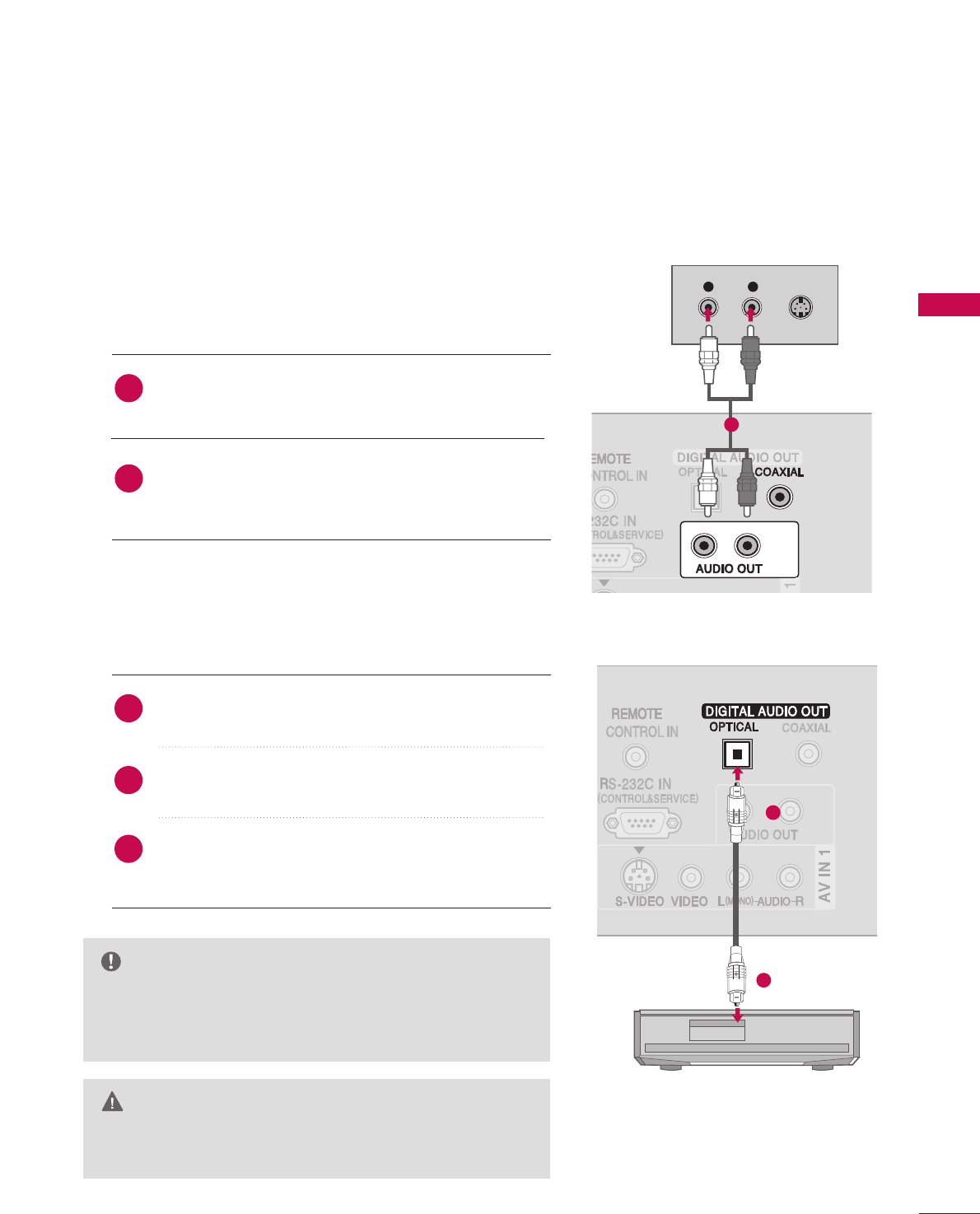
AUDIO OUT SETUP
Send the TV’s audio to external audio equipment via the Audio Output (Optical)port.
GGWhen connecting with external audio equipment, such as
amplifers or speakers, please turn the TV speakers off.
(GGpp..7722)
NOTE
GGDo not look into the optical output port. Looking at the
laser beam may damage your vision.
CAUTION
Connect one end of an optical cable to the TV Digital
Audio (Optical)Output port.
Connect the other end of the optical cable to the digi-
tal audio (optical)input on the audio equipment.
Set the “TV Speaker option - Off” in the AUDIO menu.
(GGpp..7722). See the external audio equipment instruction
manual for operation.
1. How to connect
2
3
1
1
2
L R S-VIDEO
Analog
Digital
Connect audio outputs to the TV’s AAUUDDIIOO OOUUTTor
DDIIGGIITTAALL AAUUDDIIOO OOUUTT CCOOAAXXIIAALLjacks.
Set the “TV Speaker option - Off” in the AUDIO menu.
(GGpp..7722). See the external audio equipment instruction
manual for operation.
2
1
1
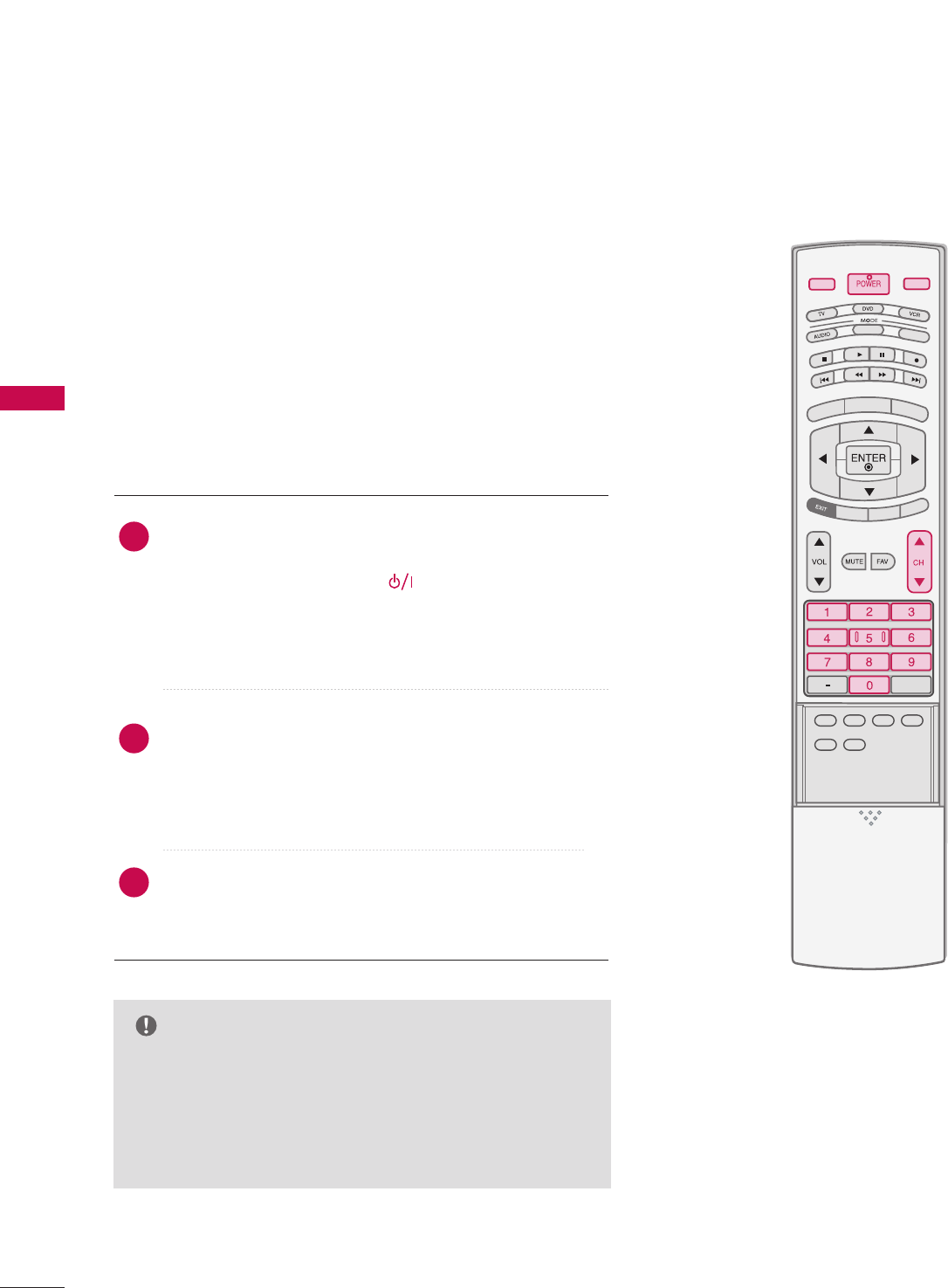
WATCHING TV / CHANNEL CONTROL
34
REMOTE CONTROL FUNCTIONS
When using the remote control, aim it at the remote control sensor on the TV.
APM
CC
AUTO DEMO
M/C EJECT
TV INPUTTV INPUT
STBSTB
MENU
BRIGHT +
BRIGHT -
TIMER
RATIO
SIMPLINK
BACKBACK
TV INPUT
STB
BACK
TV INPUT
STB
BACK
PICTURE SOUND
SAP
CC
MARK USB EJECT
MEDIA HOSTMEDIA HOST
MEDIA HOST
MEDIA HOST
BRIGHT +/-
THUMBSTICK
(Up/Down/Left
Right/ENTER)
EXIT
TIMER
RATIO
SIMPLINK
VOLUME UP
/DOWN
MUTE
FAV
CHANNEL
UP/DOWN
BACK
— (DASH)
■
Controls the mode.
■
Control video cassette recorders or DVD players.
Displays the main menu.
■
Adjust brightness on screen.
■
It turns to the default settings brightness by changing
mode source.
■
Navigate the on-screen menus and adjust the system
settings to your preference.
Clear all on-screen displays and return to TV viewing from
any menu.
Select the amount of time before your TV turns off auto-
matically.GGpp..8822
Change the aspect ratio.GGpp..5544
See a list of AV devices connected to TV.
When you toggle this button, the SimpLink menu appears
at the screen.
Increase/decrease the sound level.
Switch the sound on or off. pp..3388
Scroll through the programmed Favorite channels.
Select available channels.
Tune to the last channel viewed.
Used to enter a program number for multiple
program channels such as 2-1, 2-2, etc.
MEDIAMEDIAHOST HOST
MEDIAMEDIAHOST HOST
mode control
buttons
MEDIAMEDIAMEDIAHOST HOST HOST
MEDIAHOST
NUMBER button
VCR/DVD
buttons
MENU
WATCHING TV /CHANNEL CONTROL
WATCHING TV / CHANNEL CONTROL
35
TV INPUT
STB
BACK
TV INPUT
STB
BACK
TV INPUT
STB
BACK
BACK
PICTURE
PICTURE
SOUND
SOUND
SAP
SAP
CC
CC
MARK
MARK
USB EJECT
USB EJECT
MEDIA HOST
MEDIA HOST
MEDIA HOST
Turns your TV or any other programmed equipment on or off, depending on the mode.
In AV 1-2, Component 1-2, RGB-PC, HDMI1, HDMI2 and HDMI3 input sources, screen returns to
the last TV channel.
External input modes rotate in regular sequence: Antenna, Cable, AV1-2, Component 1-2, RGB-PC,
HDMI1, HDMI2, HDMI3 (Antenna, Cable, AV 1-2, Component 1-2, RGB-PC, HDMI1, HDMI2,
HDMI3 input sources are linked automatically, only if these are connected ).
Select the remote operating mode: TV, DVD, VCR, AUDIO, CABLE or STB.
* If the mode of another product is selected, a button on the remote control which is not used
for the selected product can control the TV.
Enter to the mode.
MEDIAMEDIAHOST HOST
MEDIAMEDIAHOST HOST
Inside the Sliding Cover
PICTURE
SOUND
SAP
CC
MARK
USB EJECT
Adjust the factory preset picture depend
on the viewing environment.
Select the appropriate type of sound for
type of program.
Select MTS sound: Mono, Stereo, and SAP
analog mode. Change the audio language
DTV mode. GGpp.. 7711
Select the Caption On/Off. GGpp..7755
Enter the selected functions. GGpp..4499
Remove the USB device. GGpp..3322
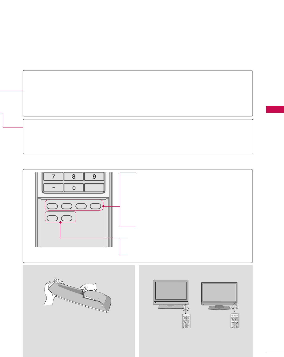
Installing Batteries
■
Open the battery compartment cover on the
back side and install the batteries matching cor-
rect polarity (+with +,-with -).
■
Install two 1.5V AA batteries. Don’t mix old or
used batteries with new ones.
■
Close cover.
R
MODE
DAY -
DAY +
LIVE TV INPUT
MODE
DAY -
DAY +
LIVE TV INPUT
■
Use a remote control up to 7 meters distance and 30
degree (left/right) within the receiving unit scope.
■
Dispose of used batteries in a recycle bin to pre-
serve environment.
Remote control effective range
POWER
TV INPUT
INPUT
MODE
MEDIAMEDIAMEDIAHOST HOST HOST
MEDIAHOST
37/42/47LB5D
32/37/42LB4D
WATCHING TV / CHANNEL CONTROL
36
WATCHING TV /CHANNEL CONTROL
TURNING ON TV
NOTE
GGIf you intend to be away on vacation, disconnect
the power plug from the wall power outlet.
GGWhen the TV is turned on, the indicator will blink
red before the picture is seen.
First, connect power cord correctly.
At this moment, the TV switches to standby mode.
■In standby mode, press the (or ON/OFF), IINNPPUUTT,
CCHH ((DD or EE))button on the TV or press the PPOOWWEERR,
IINNPPUUTT, TTVV IINNPPUUTT, CCHH((DD or EE)), NNuummbbeerr ((00~99))but-
ton on the remote control.
Select the viewing source by using the IINNPPUUTTbutton on
the remote control.
■This TV is programmed to remember which mode it was
last set to, even if you turn the TV off.
When finished using the TV, press the PPOOWWEERRbutton on
the remote control. The TV reverts to standby mode.
TV INPUT
TV INPUT
STB
STB
MENU
BRIGHT +
BRIGHT -
TIMER
RATIO
SIMPLINK
PICTUREPICTURE
PICTURE
SOUND
SOUND
SAP
SAP
CC
CC
MARK
MARK
USB EJECT
USB EJECT
INPUT
BACK
BACK
MEDIA HOST
MEDIA HOST
2
3
1
WATCHING TV / CHANNEL CONTROL
37
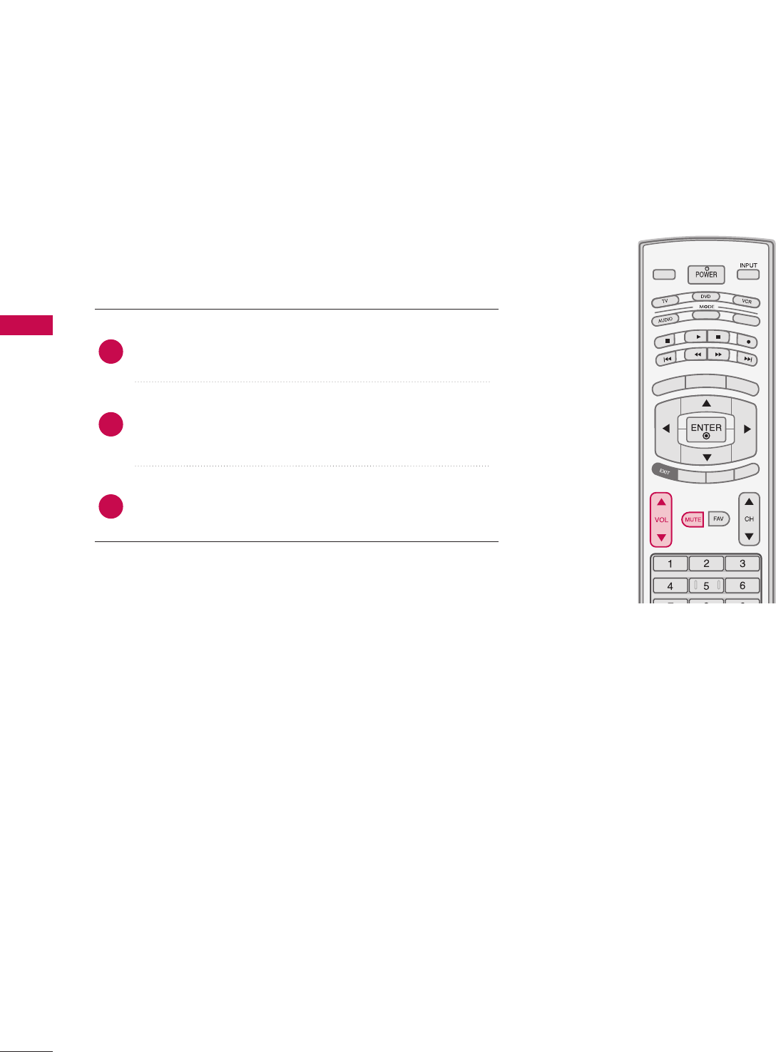
CHANNEL SELECTION
Press the CCHHDDor EE or NNUUMMBBEERRbuttons to select a
channel number.
TV INPUT
STB
TIMER
RATIO
SIMPLINK
PICTUREPICTUREPICTURE SOUNDSOUND
SAPSAP
CCCC
MARKMARK USB EJECTUSB EJECT
BACKBACK
TV INPUT
STB
BACK
PICTURE
SAP
CC
MARK USB EJECT
TV INPUT
STB
BACK
PICTURE SOUND
CC
MARK USB EJECT
TV INPUT
STB
BACK
PICTURE SOUND
SAP
MARK USB EJECT
TV INPUT
STB
BACK
SOUND
SAP
CC
MARK USB EJECT
TV INPUT
STB
BACK
PICTURE SOUND
SAP
CC
MARK USB EJECT
TV INPUT
STB
BACK
PICTURE SOUND
SAP
CC
MARK USB EJECT
TV INPUT
STB
BACK
PICTURE SOUND
SAP
CC
MARK USB EJECT
TV INPUT
STB
BACK
PICTURE SOUND
SAP
CC
MARK USB EJECT
TV INPUT
STB
BACK
PICTURE SOUND
SAP
CC
MARK USB EJECT
MEDIA HOST
MEDIA HOST
MEDIA HOST
MEDIA HOST
MEDIA HOST
MEDIA HOST
MEDIA HOST
MEDIA HOST
MEDIA HOST
MEDIA HOST
1
WATCHING TV / CHANNEL CONTROL
38
WATCHING TV /CHANNEL CONTROLWATCHING TV /CHANNEL CONTROL
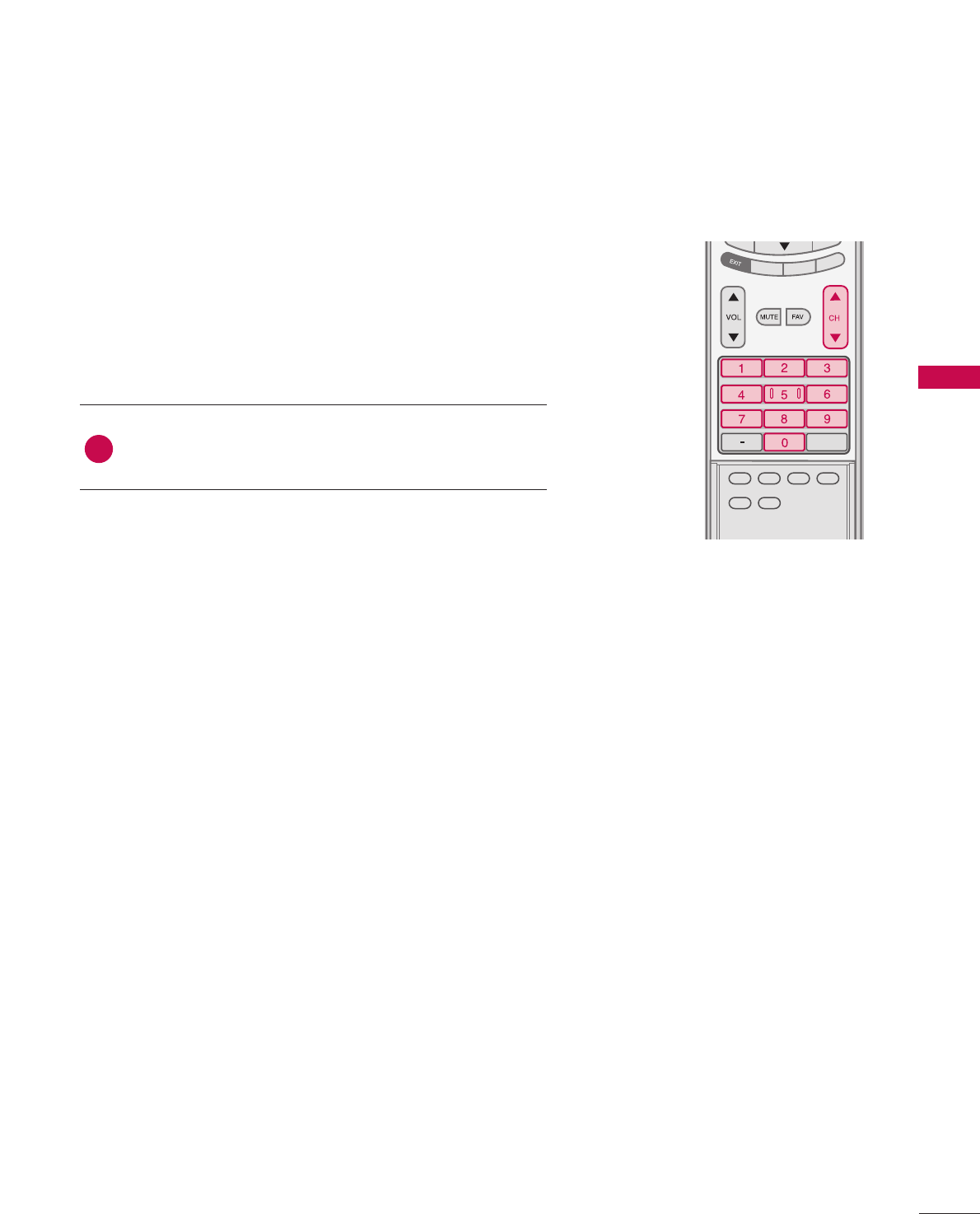
VOLUME ADJUSTMENT
Press the VVOOLLDDor EE button to adjust the volume.
If you want to switch the sound off, press the MMUUTTEEbut-
ton.
You can cancel the Mute function by pressing the MMUUTTEEor
VVOOLLDDor EE button.
Adjust the volume to suit your personal preference.
TV INPUT
STB
PICTURE SOUND
SAP
CC
MARK USB EJECT
BACK
TV INPUTTV INPUT
STBSTB
MENU
BRIGHT +
BRIGHT -
TIMER
RATIO
SIMPLINK
BACK
PICTURE
SAP
CC
MARK USB EJECT
TV INPUT
STB
BACK
PICTURE SOUND
CC
MARK USB EJECT
TV INPUT
STB
BACK
PICTURE SOUND
SAP
MARK USB EJECT
TV INPUT
STB
BACK
SOUND
SAP
CC
MARK USB EJECT
TV INPUT
STB
BACK
PICTURE SOUND
SAP
CC
MARK USB EJECT
TV INPUT
STB
BACK
PICTURE SOUND
SAP
CC
MARK USB EJECT
TV INPUT
STB
BACK
PICTURE SOUND
SAP
CC
MARK USB EJECT
TV INPUT
STB
BACK
PICTURE SOUND
SAP
CC
MARK USB EJECT
TV INPUT
STB
BACK
PICTURE SOUND
SAP
CC
MARK USB EJECT
MEDIA HOST
MEDIA HOST
MEDIA HOST
MEDIA HOST
MEDIA HOST
MEDIA HOST
MEDIA HOST
MEDIA HOST
MEDIA HOST
MEDIA HOST
MEDIA HOST
2
3
1
WATCHING TV / CHANNEL CONTROL
39
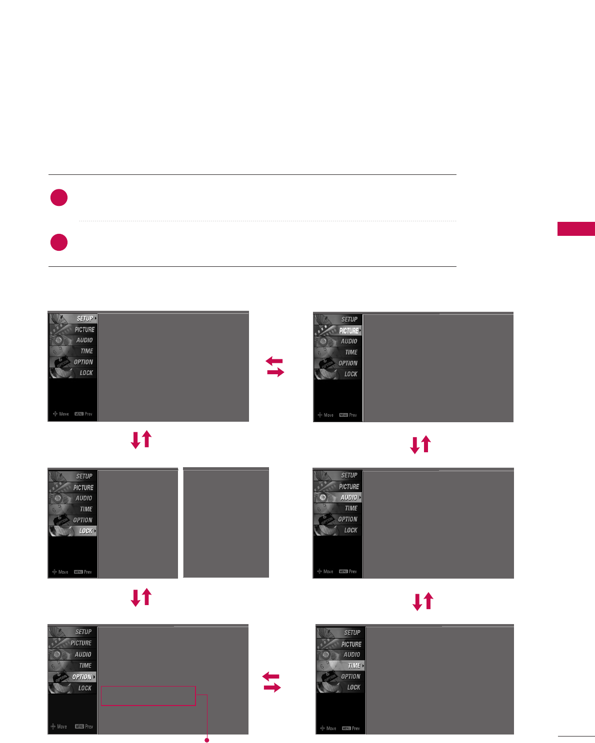
ON-SCREEN MENUS SELECTION
Press the MMEENNUUbutton and then use DDor EEbutton to select each menu.
Press the GG button and then use DDEE FFGG button to display the available menus.
Your TV's OSD (On Screen Display)may differ slightly from what is shown in this manual.
SETUP PICTURE
TIME
Auto Tuning
Manual Tuning
Channel Edit
2
1
AUDIO
Picture Mode : User1
Color Temperature : Cool
XD
Advanced
Aspect Ratio : 16:9
Picture Reset
Screen
Sound Mode : Standard
Auto Volume : On
Balance : 0
TV Speaker : On
Clock : Oct 19, 2006, 03:44 AM
Off Time : Off
On Time : Off
Sleep Time : Off
Auto Sleep : Off
Language : English
Input Label
SimpLink : Off
Key Lock : Off
Caption : Off
ISM Method : Orbiter
Low Power : Off
Set ID : 1
Lock System : Off
Set Password
Block Channel
Movie Rating
TV Rating-Children
TV Rating-General
Input Block
OPTION
LOCK
Only Plasma TV model
Lock System : Off
Set Password
Block Channel
TV Rating-English
TV Rating-French
Input Block
For USA For Canada
WATCHING TV / CHANNEL CONTROL
40
WATCHING TV /CHANNEL CONTROL
Auto Tuning G
Manual Tuning
Channel Edit
Selection ( Gor ) leads you to
the Auto Tuning screen.
TV INPUT
STB
PICTURE SOUND
SAP
CC
MARK USB EJECT
BACK
TV INPUT
STB
BACK
PICTURE
SAP
CC
MARK USB EJECT
TV INPUT
STB
BACK
PICTURE SOUND
CC
MARK USB EJECT
TV INPUT
TV INPUT
STB
STB
BRIGHT +
BRIGHT -
TIMER
RATIO
SIMPLINK
BACK
PICTURE SOUND
SAP
MARK USB EJECT
MENU
TV INPUT
STB
BACK
SOUND
SAP
CC
MARK USB EJECT
TV INPUT
STB
BACK
PICTURE SOUND
SAP
CC
MARK USB EJECT
TV INPUT
STB
BACK
PICTURE SOUND
SAP
CC
MARK USB EJECT
TV INPUT
STB
BACK
PICTURE SOUND
SAP
CC
MARK USB EJECT
TV INPUT
STB
BACK
PICTURE SOUND
SAP
CC
MARK USB EJECT
TV INPUT
STB
BACK
PICTURE SOUND
SAP
CC
MARK USB EJECT
MEDIA HOST
MEDIA HOST
MEDIA HOST
MEDIA HOST
MEDIA HOST
MEDIA HOST
MEDIA HOST
MEDIA HOST
MEDIA HOST
MEDIA HOST
MEDIA HOST
Press the MMEENNUUbutton and then use DDor EEbut-
ton to select the SSEETTUUPPmenu.
Press the GG button and then use DDor EEbutton to
select AAuuttoo TTuunniinngg.
Press the EENNTTEERRbutton to begin the channel
search. Allow AAuuttoo TTuunniinnggto complete the channel
search cycle for AANNTTEENNNNAAand CCAABBLLEE.
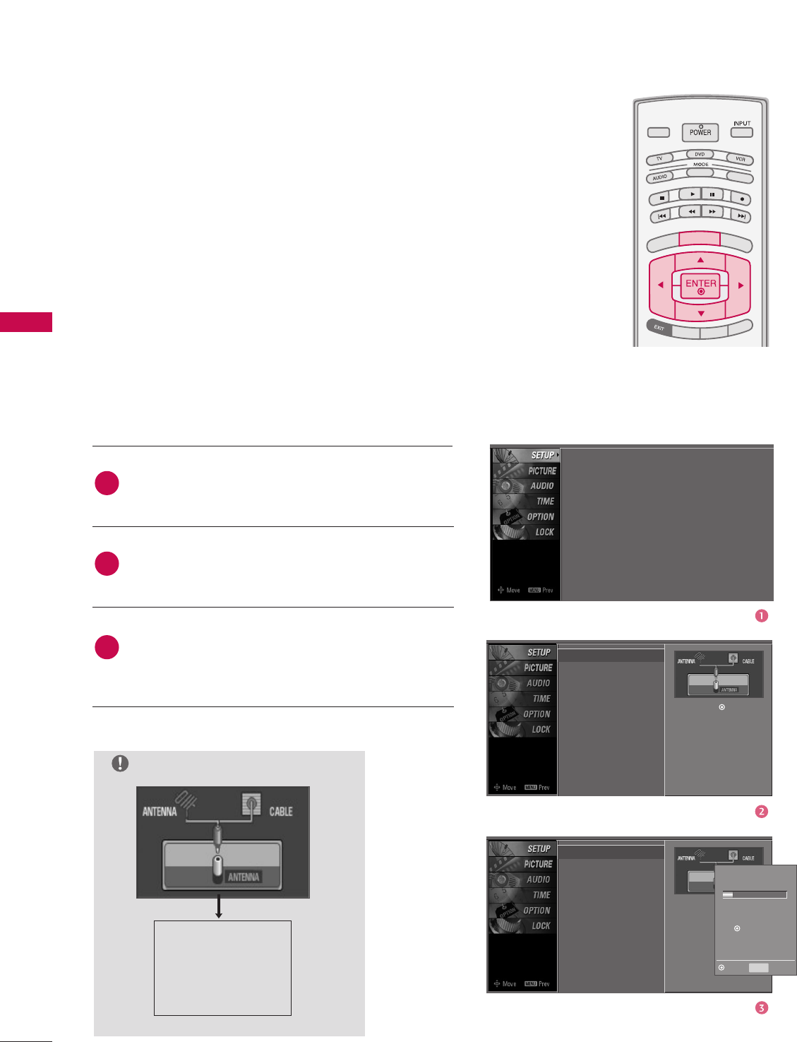
Automatically finds all channels available through antenna or
cable inputs, and stores them in memory on the channel list.
Run Auto Tuning again after any Antenna/Cable connection
changes.
A password is required to gain access to Auto Tuning menu if
the Lock System is turned on.
Auto Tuning
Manual Tuning
Channel Edit
Selection ( Gor ) leads
you to the Auto Tuning
screen.
2
3
1
NOTE
Analog TV antenna
Digital DTV antenna
Analog CATV cable
Digital CADTV cable
Processing Auto Tuning...
DTV Ch.23
Found Channel(s): 16
Press to stop the current
scan and start ANALOG
ANTENNA channel scan.
MENU Prev
Next
Auto Tuning
Manual Tuning
Channel Edit
CHANNEL SETUP
Auto Scan(Auto Tuning)
WATCHING TV / CHANNEL CONTROL
41
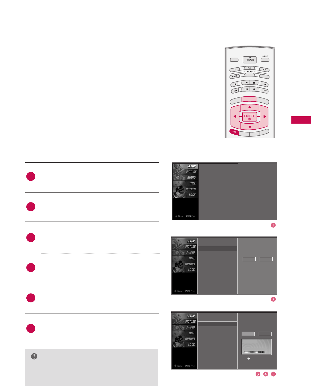
Auto Tuning
Manual Tuning G
Channel Edit
A password is required to gain access to Manual Tuning
menu if the Lock System is turned on.
If selecting DTV or CADTV input signal, you can view the
on-screen signal strength monitor to see the quality of
the signal being received.
Press the MMEENNUUbutton and then use DDor EEbutton
to select the SSEETTUUPPmenu.
Press the GG button and then use DDor EEbutton to
select MMaannuuaall TTuunniinngg.
Press the GG button and then use DDor EEbutton to
select DTV, TV, CADTV, and CATV.
Press the GG button and then use DDor EEbutton to
select channel number you want to add or delete.
Press the EENNTTEERRbutton to add or delete for the
channel number.
Press EEXXIITTbutton to return to TV viewing or press
MMEENNUUbutton to return to the previous menu.
TV INPUT
STB
PICTURE SOUND
SAP
CC
MARK USB EJECT
BACK
TV INPUT
STB
BACK
PICTURE
SAP
CC
MARK USB EJECT
TV INPUTTV INPUT
STBSTB
BRIGHT +
BRIGHT -
TIMER
RATIO
SIMPLINK
BACK
PICTURE SOUND
CC
MARK USB EJECT
MENU
TV INPUT
STB
BACK
PICTURE SOUND
SAP
MARK USB EJECT
TV INPUT
STB
BACK
SOUND
SAP
CC
MARK USB EJECT
TV INPUT
STB
BACK
PICTURE SOUND
SAP
CC
MARK USB EJECT
TV INPUT
STB
BACK
PICTURE SOUND
SAP
CC
MARK USB EJECT
TV INPUT
STB
BACK
PICTURE SOUND
SAP
CC
MARK USB EJECT
TV INPUT
STB
BACK
PICTURE SOUND
SAP
CC
MARK USB EJECT
TV INPUT
STB
BACK
PICTURE SOUND
SAP
CC
MARK USB EJECT
MEDIA HOST
MEDIA HOST
MEDIA HOST
MEDIA HOST
MEDIA HOST
MEDIA HOST
MEDIA HOST
MEDIA HOST
MEDIA HOST
MEDIA HOST
MEDIA HOST
Select channel type and
RF-channel number.
DTV 2
4
5
6
2
3
1
Auto Tuning
Manual Tuning
Channel Edit
Select channel type and
RF-channel number.
DTV GG12
Press to delete the channel.
DTV 12-0
DD
EE
Bad Normal Good
Auto Tuning
Manual Tuning
Channel Edit
Add/Delete Channel(Manual Tuning)
NOTE
GGThis digital channel number is a physical channel
number, which is different from the normal channel
number shown in Channel Edit.
WATCHING TV / CHANNEL CONTROL
42
WATCHING TV /CHANNEL CONTROL
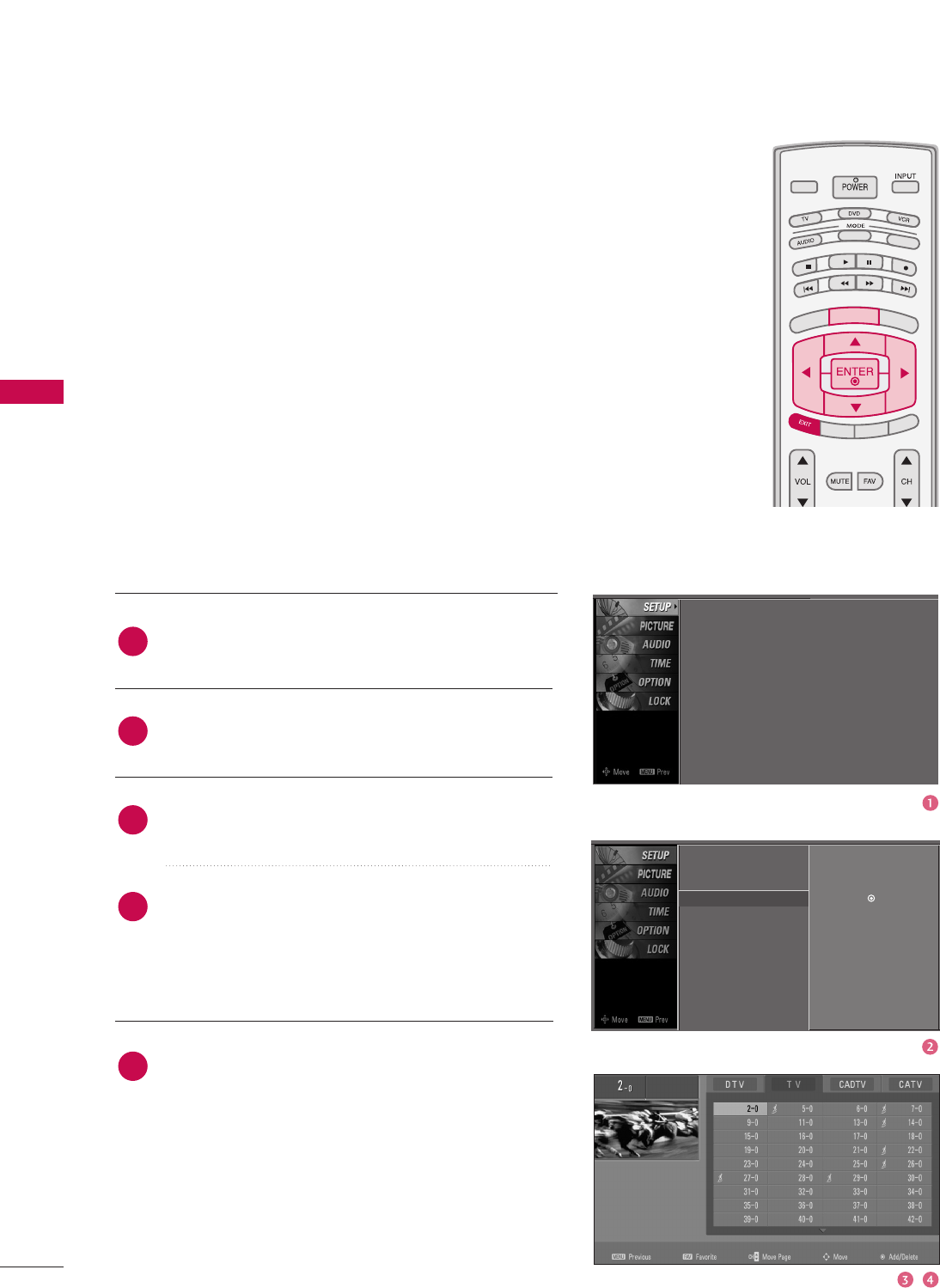
Press the MMEENNUUbutton and then use DDor EEbutton
to select the SSEETTUUPPmenu.
Press the GG button and then use DDor EEbutton to
select CChhaannnneell EEddiitt.
Press the GG button. You will now see a screen filled
with channel numbers and a preview picture.
Use DDEE FFGG button to select a channel and then
use the EENNTTEERRbutton to add or delete it. Press
FFAAVVbutton to add the channel to the Favorite List.
The surfing icon will appear in front of that channel
number.
Press EEXXIITTbutton to return to TV viewing or press
MMEENNUUbutton to return to the previous menu.
TV INPUT
STB
PICTURE SOUND
SAP
CC
MARK USB EJECT
BACK
TV INPUT
STB
BACK
PICTURE
SAP
CC
MARK USB EJECT
TV INPUTTV INPUT
STBSTB
BRIGHT +
BRIGHT -
TIMER
RATIO
SIMPLINK
BACK
PICTURE SOUND
CC
MARK USB EJECT
MENU
TV INPUT
STB
BACK
PICTURE SOUND
SAP
MARK USB EJECT
TV INPUT
STB
BACK
SOUND
SAP
CC
MARK USB EJECT
TV INPUT
STB
BACK
PICTURE SOUND
SAP
CC
MARK USB EJECT
TV INPUT
STB
BACK
PICTURE SOUND
SAP
CC
MARK USB EJECT
TV INPUT
STB
BACK
PICTURE SOUND
SAP
CC
MARK USB EJECT
TV INPUT
STB
BACK
PICTURE SOUND
SAP
CC
MARK USB EJECT
TV INPUT
STB
BACK
PICTURE SOUND
SAP
CC
MARK USB EJECT
MEDIA HOST
MEDIA HOST
MEDIA HOST
MEDIA HOST
MEDIA HOST
MEDIA HOST
MEDIA HOST
MEDIA HOST
MEDIA HOST
MEDIA HOST
MEDIA HOST
From the default channel list created from the Auto Tuning
channel search, you can create two different types of channel
lists in memory: “custom list” and “favorite channel list”.
A custom list can be created by toggling each channel on or off
with ENTER button. The channels in the Custom List are dis-
played in black and the channels deleted from the Custom List
are displayed in gray. Once a channel is highlighted you can add
or delete the channel by referring to the small window at the
top-left corner of the screen.
You can create your own Favorite List. Use the FFAAVVbutton on
the remote control when a channel is highlighted and then add
or delete the channel to/from your Favorite List.
Auto Tuning
Manual Tuning
Channel Edit GSelection ( Gor ) leads you to the
channel edit screen.
4
5
2
3
1
Auto Tuning
Manual Tuning
Channel Edit
Channel Editing
WATCHING TV / CHANNEL CONTROL
43
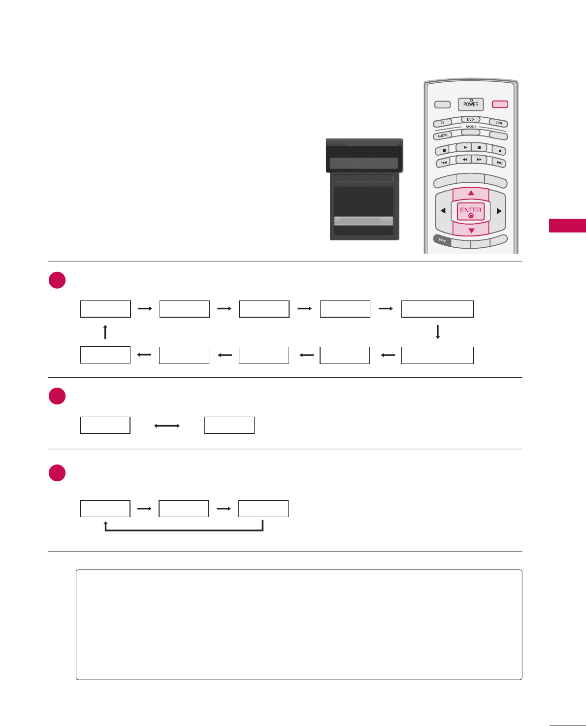
INPUT LIST
AAnntteennnnaa: Select it when watching the DTV/TV.
CCaabbllee: Select it when watching the CADTV/CATV.
AAVV 11,, AAVV 22: Select it when watching the VCR or external equipment.
CCoommppoonneenntt 11--22: Select it when using the DVD or the Digital set-top box depend on connector.
RRGGBB--PPCC: Select it when using PC depend on connector.
HHDDMMII,, HHDDMMII22,, HHDDMMII33: Select it when using DVD, PC or Digital set-top box depend on connector.
Antenna
Cable
AV 1
AV 2
Component1
EE
Input List
AV 2
Press theIINNPPUUTTbutton to display external device that is
connected to the unit, on screen.
Press the EENNTTEERRbutton to change the input to the active
external device. Use the DDor EE button to select the
input source.
TV INPUT
STBSTB
MENU
BRIGHT +
BRIGHT -
TIMER
RATIO
SIMPLINK
PICTURE SOUND
SAP
CC
MARK USB EJECT
INPUT
MEDIA HOST
MEDIA HOST
AAnntteennnnaaCCaabbllee
If all external input sources are connected:
If no external input sources are not connected:
If there is any external input source connected:
(ex: When connected only to AV 2)
AAnntteennnnaaCCaabbllee
AAVV11
AAnntteennnnaaCCaabblleeAAVV22
AAVV22CCoommppoonneenntt11
HHDDMMII22HHDDMMII11RRGGBB--PPCCCCoommppoonneenntt22
2
3
1
HHDDMMII33
WATCHING TV / CHANNEL CONTROL
44
WATCHING TV /CHANNEL CONTROLWATCHING TV /CHANNEL CONTROL
This operates only for the devices with the
logo. Please check the logo.
This allows you to control and play other AV devices
connected to the display through HDMI cable without
additional cables and settings.
TV INPUTTV INPUT
STBSTB
MENU
BRIGHT +
BRIGHT -
TIMER
RATIO
SIMPLINK
BACK
PICTURE SOUND
SAP
CC
MARK USB EJECT
MEDIA HOST
MEDIA HOST
TV INPUT
STB
BACK
PICTURE SOUND
SAP
CC
MARK USB EJECT
MEDIA HOST
MENU
Connect the HDMI/DVI IN 1, 2 or 3 terminal of the
TV to the rear terminal (HDMI output) of the
SimpLink device with the HDMI cable.
After connecting the HDMI jack for the home theater
with simpLink function in the above method, connect
the DIGITAL AUDIO OUT OPTICAL on the back of
the TV to the DIGITAL AUDIO OUT terminal on the
back of the simpLink device with the Optical cable.
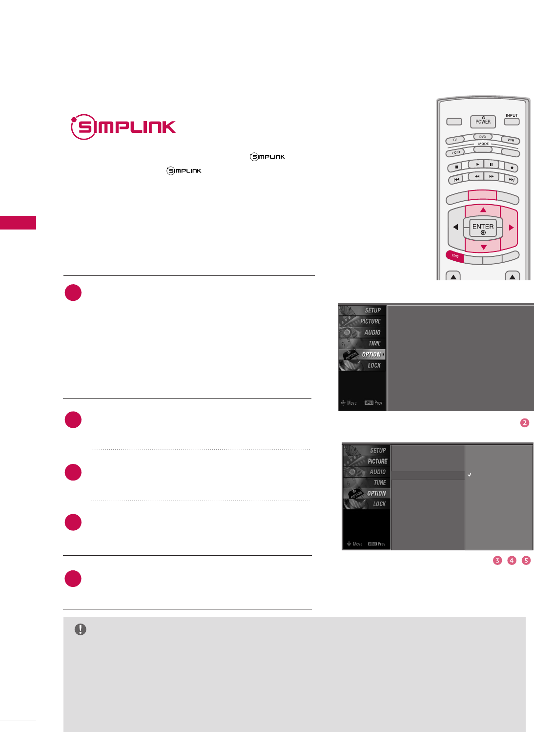
Press the MMEENNUUbutton and then use DDor EEbutton
to select the OOPPTTIIOONNmenu.
Press the GG button and then use DDor EEbutton to
select SSiimmppLLiinnkk.
Press the GG button and then use DDor EEbutton to
select OOnn.
Press EEXXIITTbutton to return to TV viewing or press
MMEENNUUbutton to return to the previous menu.
4
2
3
1
Language : English
Input label
SimpLink : Off
Key Lock : Off
Caption : Off
ISM Method : Orbiter
Low Power : Off
Set ID : 1
Language
Input label
SimpLink G
Key Lock
Caption
ISM Method
Low Power
Set ID
Off
On
NOTE
GGWhen operating the external device with SimpLink, press the TV button among the MODE button on
the remote control.
GGWhen you switch the Input source with the INPUT button on the remote control, you can stop the
operation of device worked by SimpLƒink.
GGWhen you select or operate the media device with home theater function, the speaker automatically
switches to home theater speaker (HT speaker).
GGWhen you execute ‘Photo List, Music List ’function during DVD playback included in home theater sup-
ported the SimpLink stops and the applicable function is executed after switching the input to TV.
SimpLink Preparations
5
WATCHING TV / CHANNEL CONTROL
45
SimpLink Functions
DDiirreecctt PPllaayy
After connecting AV devices to TV, you can directly control the devices and play media
without additional settings.
SSeelleecctt AAVV ddeevviiccee
Enables you to select one of AV devices connected to TV and play it.
DDiisscc ppllaayybbaacckk
Control connected AV devices by pressing the , , , , , , ,
DDEEFF GG, EENNTTEERRbuttons and buttons for play, pause, stop, fast reverse, fast forward,
chapter skip.
PPoowweerr ooffff aallll ddeevviicceess
When you power off TV, all connected devices are turned off.
SSwwiittcchh aauuddiioo--oouutt
Offers an easy way to switch audio-out.
(A device, which is connected to TV through HDMI cable but does not support
Simplink, does not provide this function)
SimpLink Menu
DDIISSCC ppllaayybbaacckk: Select and play discs.
When multiple discs are available, the
titles of the discs are conveniently dis-
played at the bottom of the screen.
VVCCRR ppllaayybbaacckk: Play and control the
connected VCR.
HHDDDD RReeccoorrddiinnggss ppllaayybbaacckk: Play and
control recordings stored in HDD.
AAuuddiioo OOuutt ttoo HHTT ssppeeaakkeerr//AAuuddiioo
OOuutt ttoo TTVV: Select HT speaker or TV
speaker for Audio Out.
TTVV vviieewwiinngg : Switch to the previous TV
channel regardless of the current mode.
GGSelected Device
GGWhen no device is
connected (displayed in gray)
GGWhen a device is
connected (displayed in
bright color)
1
2
3
4
5
TV INPUT
STB
BACK
PICTURE SOUND
SAP
CC
MARK USB EJECT
MEDIA HOST
TV INPUTTV INPUT
STBSTB
MENU
BRIGHT +
BRIGHT -
TIMER
RATIO
SIMPLINK
BACK
PICTURE SOUND
SAP
CC
MARK USB EJECT
MEDIA HOST
MEDIA HOST
SIMPLINKSIMPLINK
After selecting the TTVVbutton of the MODE on the remote control,
press the SSIIMMPPLLIINNKKbutton.
Use DDEE FFGG button to select the desired device and then press
the EENNTTEERRbutton.
Control connected AV devices by pressing the , , ,
,,,, DDEEFF GG, EENNTTEERRbuttons.
2
1
3
1
2
3
4
5
WATCHING TV / CHANNEL CONTROL
46
WATCHING TV /CHANNEL CONTROLWATCHING TV /CHANNEL CONTROL
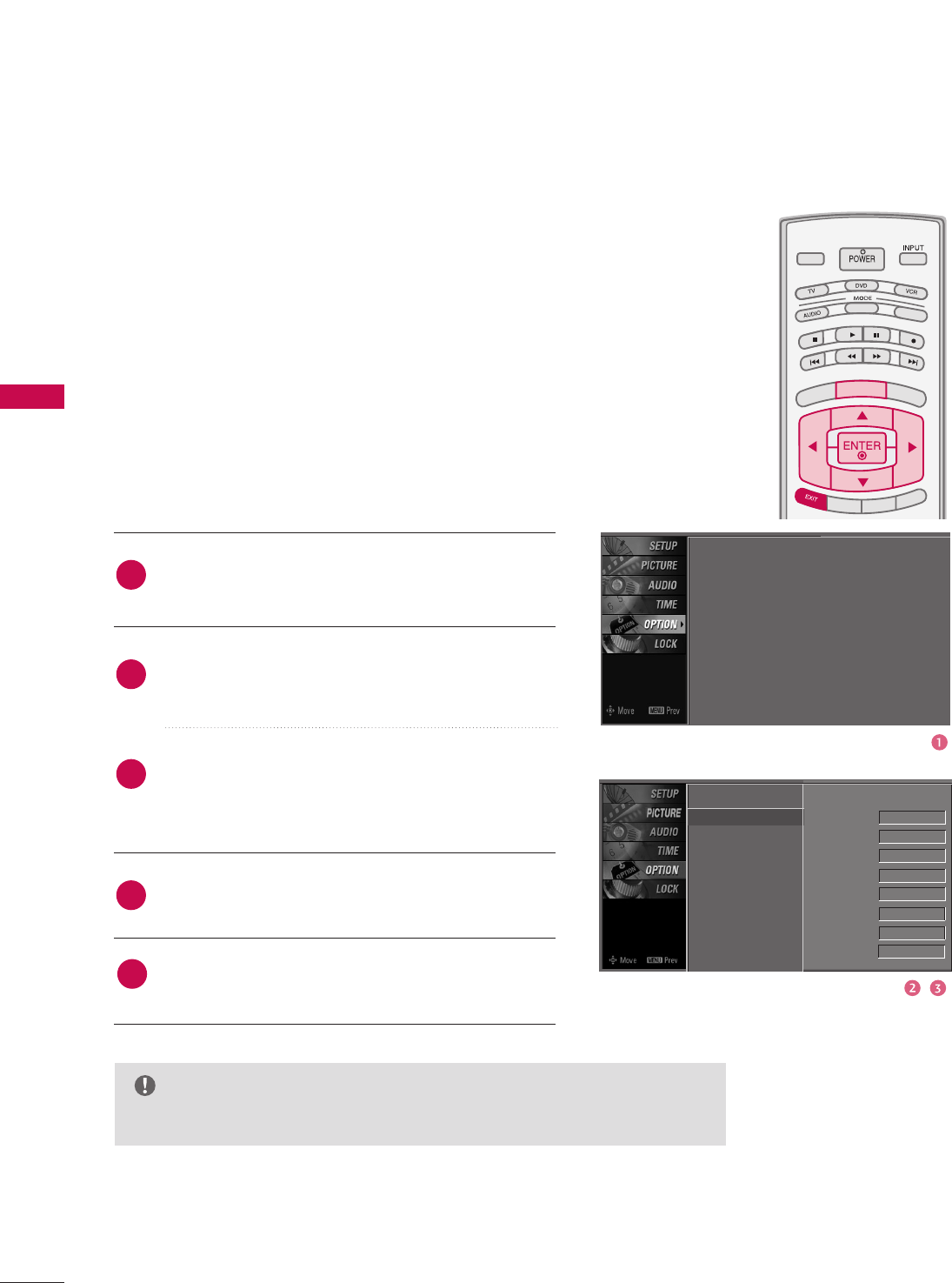
INPUT LABEL
Sets a label to each input source which is not in use when you
press INPUT button.
Press the MMEENNUUbutton and then use DDor EEbut-
ton to select the OOPPTTIIOONNmenu.
Press the GG button and then use DDor EEbutton to
select IInnppuutt LLaabbeell.
Press the GG button and then use DDor EEbutton to
select the source: AV1, AV2, Component1,
Component2, RGB-PC, HDMI1, HDMI2 or HDMI3.
Press the FFor GGbutton to select the label.
Press EEXXIITTbutton to return to TV viewing or press
MMEENNUUbutton to return to the previous menu.
TV INPUT
STB
PICTURE SOUND
SAP
CC
MARK USB EJECT
BACK
TV INPUT
STB
BACK
PICTURE
SAP
CC
MARK USB EJECT
TV INPUTTV INPUT
STBSTB
BRIGHT +
BRIGHT -
TIMER
RATIO
SIMPLINK
BACK
PICTURE SOUND
CC
MARK USB EJECT
MENU
TV INPUT
STB
BACK
PICTURE SOUND
SAP
MARK USB EJECT
TV INPUT
STB
BACK
SOUND
SAP
CC
MARK USB EJECT
TV INPUT
STB
BACK
PICTURE SOUND
SAP
CC
MARK USB EJECT
TV INPUT
STB
BACK
PICTURE SOUND
SAP
CC
MARK USB EJECT
TV INPUT
STB
BACK
PICTURE SOUND
SAP
CC
MARK USB EJECT
TV INPUT
STB
BACK
PICTURE SOUND
SAP
CC
MARK USB EJECT
TV INPUT
STB
BACK
PICTURE SOUND
SAP
CC
MARK USB EJECT
MEDIA HOST
MEDIA HOST
MEDIA HOST
MEDIA HOST
MEDIA HOST
MEDIA HOST
MEDIA HOST
MEDIA HOST
MEDIA HOST
MEDIA HOST
MEDIA HOST
Language
Input label G
SimpLink
Key Lock
Caption
ISM Method
Low Power
Set ID
AV1 Cable Box
AV2 VCR
Component1 DVD
Component2 Set Top Box
RGB-PC VCR
HDMI1 Game
HDMI2 Satellite
HDMI3 Cable Box
2
3
4
1
5
Language : English
Input label
SimpLink : Off
Key Lock : Off
Caption : Off
ISM Method : Orbiter
Low Power : Off
Set ID : 1
NOTE
GGWhen selecting the PC of HDMI mode, the picture is changed to full screen.
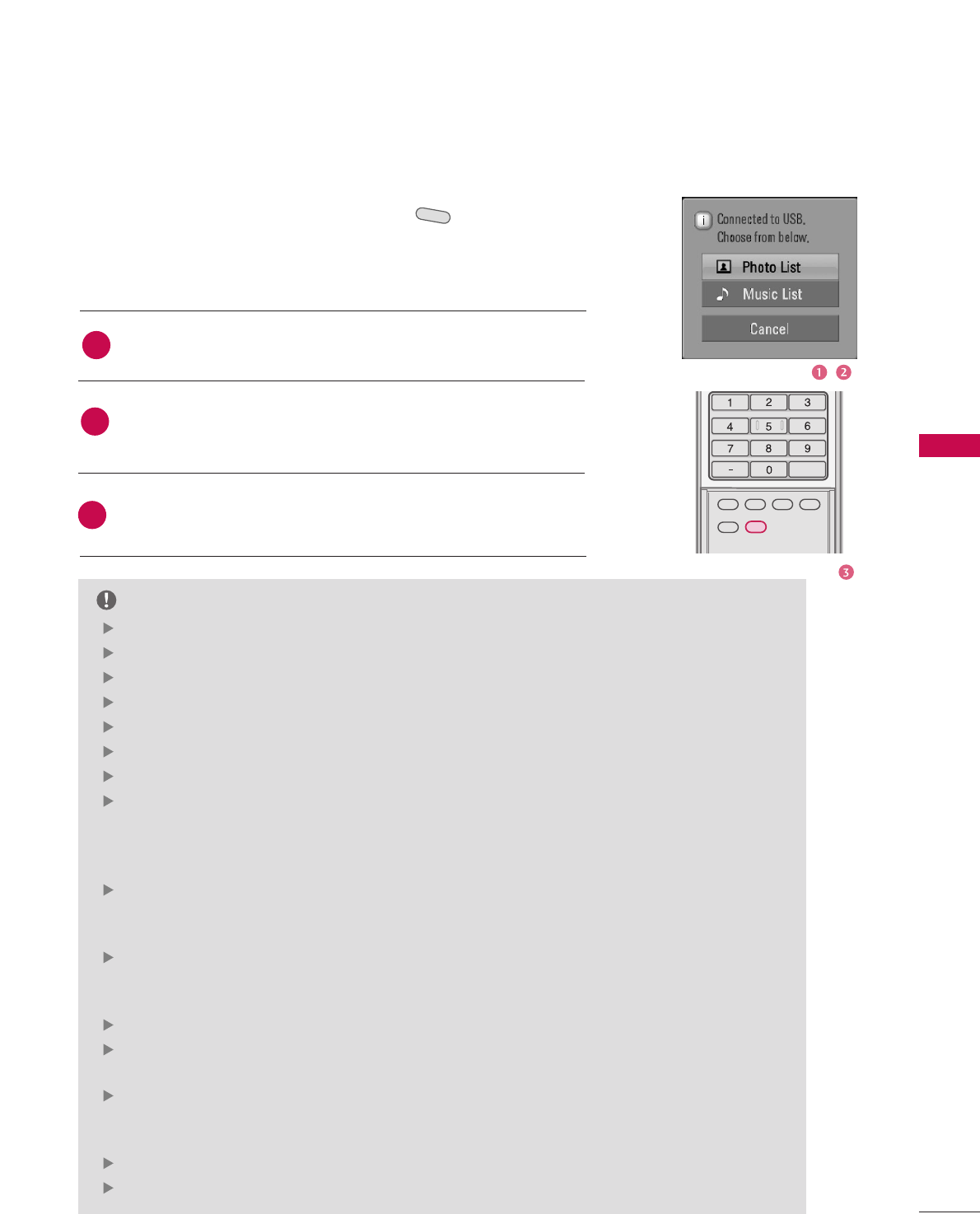
MEDIA HOST
47
MEDIAMEDIAMEDIAHOST HOST HOST
MEDIAHOST
When you connect a USB device or press the button, this screen is
displayed, automatically.
In USB device, you can not add a new folder or delete the existing folder.
MEDIA HOST
MEDIA HOST
ENTRY MODES
Press the DD or EEbutton to select the desired item.
Press the EENNTTEERRbutton to move to PPhhoottoo LLiisstt or MMuussiicc LLiisstt of
USB device.
Press the UUSSBB EEJJEECCTTbutton of remote control before removing
the USB device.
1
2
NOTE
3
BACKBACK
PICTUREPICTURE SOUNDSOUND
SAPSAP
MARKMARK
USB EJECTUSB EJECT
CCCC
[Media Host Menu]
Press the UUSSBB EEJJEECCTTbutton of remote control before removing the USB device.
Only a USB storage device is recognizable.
If the USB storage device is connected through a USB hub, the device is not recognizable.
A USB storage device using an automatic recognition program may not be recognized.
A USB storage device which uses its own driver may not be recognized.
In case of a card reader, up to four memory cards are concurrently recognizable.
The recognition speed of a USB storage device may depend on each device.
Please do not turn off the TV or unplug the USB device when the connected USB storage
device is working. When such device is suddenly separated or unplugged, the stored files or
the USB storage device may be damaged. To unplug the USB storage device, please press the
UUSSBB EEJJEECCTTbutton on the remote control, and then unplug it safely.
Please do not connect the USB storage device which was artificially maneuvered on the PC.
The device may cause the product to malfunction or fail to be played. Never forget to use only
a USB storage device which has normal music files or image files.
Please use only a USB storage device which was formatted as a FAT or a NTFS file system pro-
vided with the Windows operating system. In case of a storage device formatted as a different
utility program which is not supported by Windows, it may not be recognized.
In case of a hard disk drive (HDD) formatted as NTFS, writing and deletion are not allowable.
Please connect power to a USB storage device which requires an external power supply. If not,
the device may not be recognized.
Please connect a USB storage device with cable is offered by USB maker. If connected with
cable is not offered by USB maker or an excessively long cable, the device may not be recog-
nized.
Some USB storage devices may not be supported or operated smoothly.
If the name of a folder or file is too long, it will not be displayed or recognized.
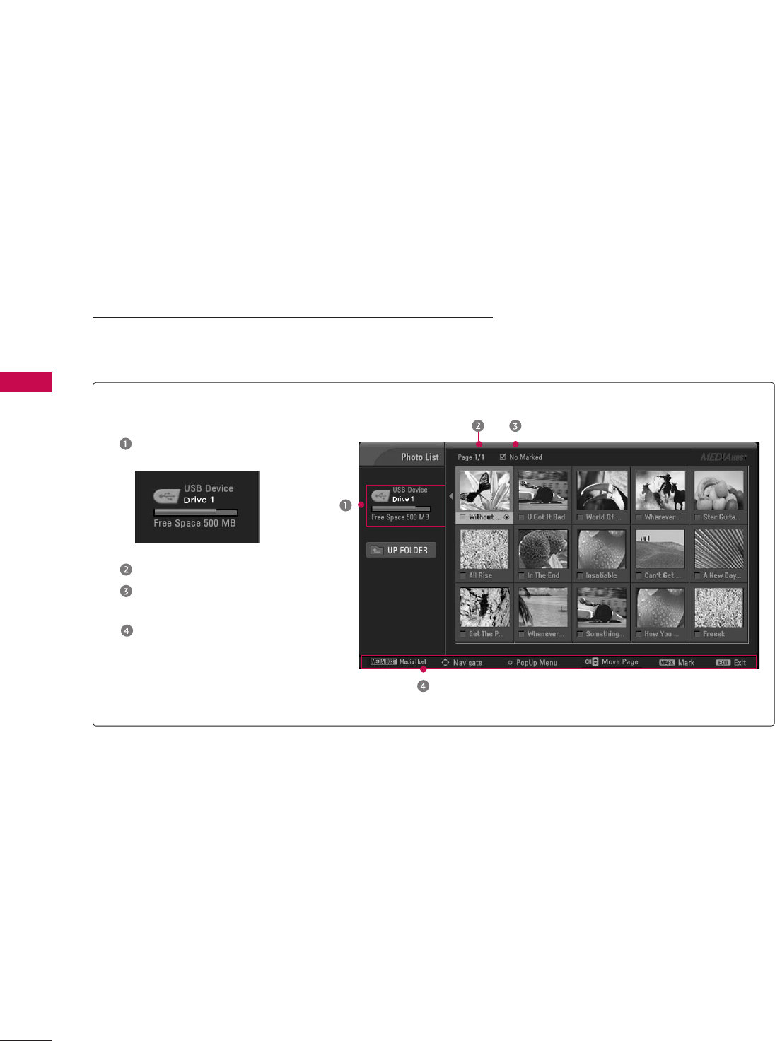
MEDIA HOST
48
MEDIAMEDIAHOST HOST
MEDIAMEDIAHOST HOST
Screen Components
Current page/Total pages
Total number of marked
thumbnail photos
Corresponding buttons
on the remote control
Usable USB memory
It’s available to playback the photo file(*.jpg) in the USB device.
The On Screen Display may be different from your set. Images
are an example to assist with the TV operation.
PHOTO LIST