LG Electronics USA 42LG30DCUA LCD TV/MONITOR User Manual SAC307080 Edit1 en 6
LG Electronics USA LCD TV/MONITOR SAC307080 Edit1 en 6
Contents
- 1. User manual 1 of 2
- 2. User manual 2 of 2
User manual 1 of 2
Please read this manual carefully before operating
your set.
Retain it for future reference.
Record model number and serial number of the set.
See the label attached on the back cover and quote
this information to your dealer
when you require service.
LCD TV PLASMA TV
OWNER’S MANUAL
LCD TV MODELS
32LG30DC
37LG30DC
42LG30DC
47LG50DC
52LG50DC
PLASMA TV MODELS
42PG60C
P/NO : SAC307080? (0805-REV00)
www.lgcommercial.com
As an ENERGY STAR Partner
LG Electronics USA, Inc.
has determined that this
product meets the ENERGY
STAR guidelines for energy
efficiency.
ENERGY STAR is a set of power-saving
guidelines issued by the U.S.
Environmental Protection Agency (EPA).
2
WARNING / CAUTION
WARNING / CAUTION
To prevent fire or shock hazards, do not expose
this product to rain or moisture.
FCC NOTICE
Class B digital device
This equipment has been tested and found to comply
with the limits for a Class B digital device, pursuant to
Part 15 of the FCC Rules. These limits are designed
to provide reasonable protection against harmful
interference in a residential installation. This equipment
generates, uses and can radiate radio frequency energy
and, if not installed and used in accordance with the
instructions, may cause harmful interference to radio
communications. However, there is no guarantee that
interference will not occur in a particular installation.
If this equipment does cause harmful interference to
radio or television reception, which can be determined
by turning the equipment off and on, the user is
encouraged to try to correct the interference by one
or more of the following measures:
- Reorient or relocate the receiving antenna.
- Increase the separation between the equipment and
receiver.
- Connect the equipment to an outlet on a circuit
different from that to which the receiver is connected.
- Consult the dealer or an experienced radio/TV
technician for help.
Any changes or modifications not expressly approved
by the party responsible for compliance could void
the user’s authority to operate the equipment.
CAUTION
Do not attempt to modify this product in any way
without written authorization from LG Electronics.
Unauthorized modification could void the user’s
authority to operate this product
The lightning flash with arrowhead
symbol, within an equilateral triangle, is
intended to alert the user to the presence
of uninsulated “dangerous voltage” within the
product’s enclosure that may be of sufficient
magnitude to constitute a risk of electric shock to
persons.
The exclamation point within an equilateral
triangle is intended to alert the user to
the presence of important operating and
maintenance (servicing) instructions in the litera-
ture accompanying the appliance.
TO REDUCE THE RISK OF ELECTRIC SHOCK
DO NOT REMOVE COVER (OR BACK). NO
USER SERVICEABLE PARTS INSIDE. REFER TO
QUALIFIED SERVICE PERSONNEL.
WARNING/CAUTION
TO REDUCE THE RISK OF FIRE AND ELECTRIC
SHOCK, DO NOT EXPOSE THIS PRODUCT TO
RAIN OR MOISTURE.
NOTE TO CABLE/TV INSTALLER
This reminder is provided to call the CATV system
installer’s attention to Article 820-40 of the National
Electric Code (U.S.A.). The code provides guidelines for
proper grounding and, in particular, specifies that the
cable ground shall be connected to the grounding system
of the building, as close to the point of the cable entry
as practical.
3
IMPORTANT SAFETY INSTRUCTIONS
SAFETY INSTRUCTIONS
Read these instructions.
Keep these instructions.
Heed all warnings.
Follow all instructions.
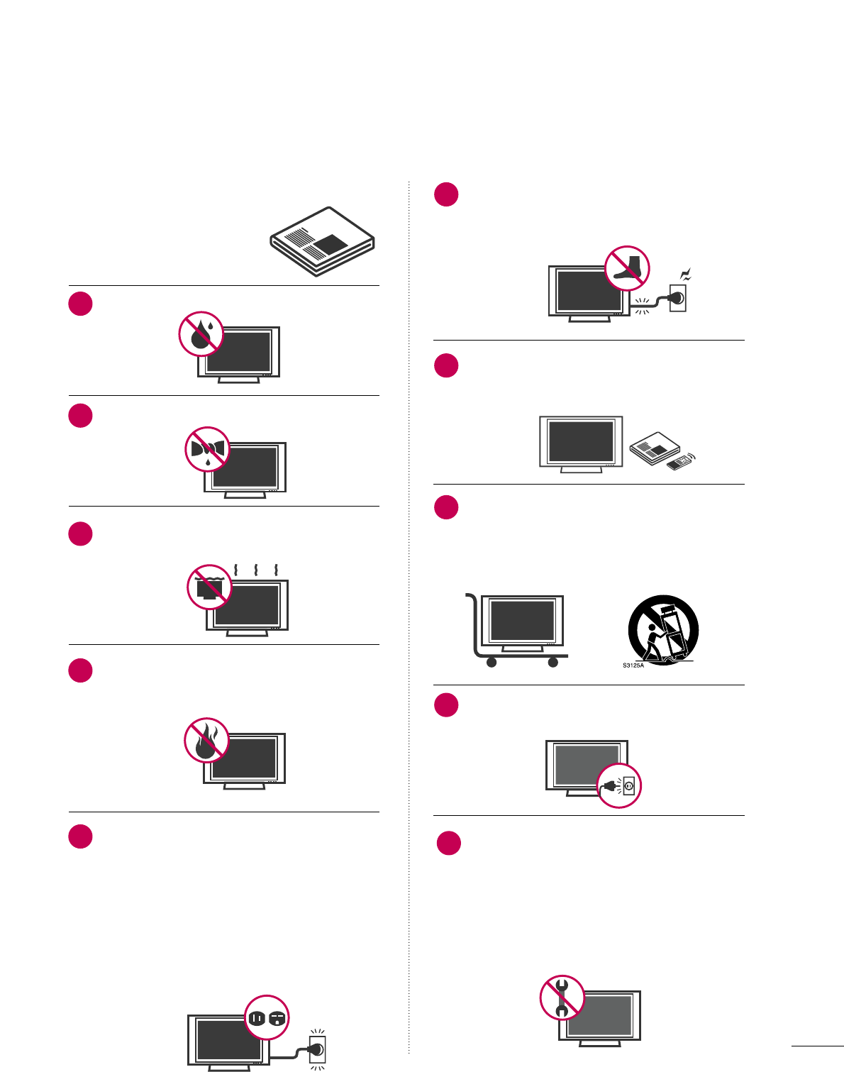
Do not use this apparatus near water.
Clean only with dry cloth.
Do not block any ventilation openings. Install in
accordance with the manufacturer’s instructions.
Do not install near any heat sources such as
radiators, heat registers, stoves, or other
apparatus (including amplifiers)that produce
heat.
Do not defeat the safety purpose of the polarized
or grounding-type plug. A polarized plug has
two blades with one wider than the other. A
grounding type plug has two blades and a
third grounding prong, The wide blade or the
third prong are provided for your safety. If the
provided plug does not fit into your outlet,
consult an electrician for replacement of the
obsolete outlet.
Protect the power cord from being walked on
or pinched particularly at plugs, convenience
receptacles, and the point where they exit from
the apparatus.
Only use attachments/accessories specified by
the manufacturer.
Use only with the cart, stand, tripod, bracket,
or table specified by the manufacturer, or sold
with the apparatus. When a cart is used, use
caution when moving the cart/apparatus com-
bination to avoid injury from tip-over.
Unplug this apparatus during lighting storms
or when unused for long periods of time.
Refer all servicing to qualified service personnel.
Servicing is required when the apparatus has
been damaged in any way, such as power-
supply cord or plug is damaged, liquid has
been spilled or objects have fallen into the
apparatus, the apparatus has been exposed to
rain or moisture, does not operate normally, or
has been dropped.
1
2
3
4
5
7
6
8
9
10
4
SAFETY INSTRUCTIONS
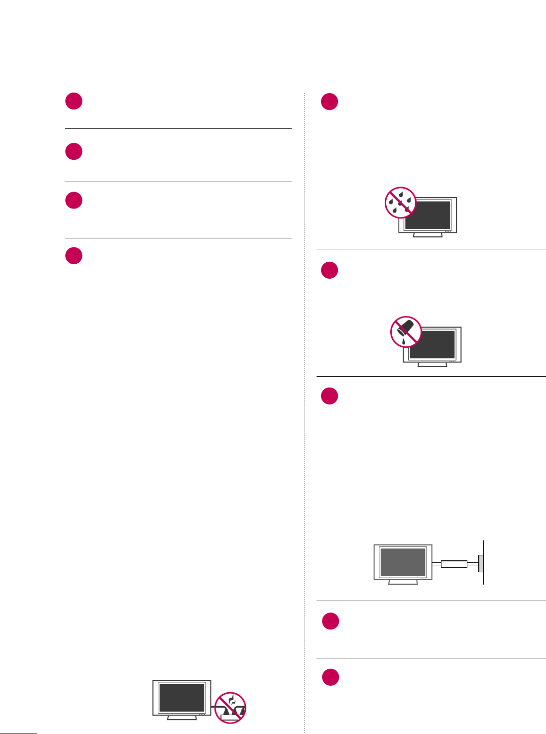
Never touch this apparatus or antenna during
a thunder or lighting storm.
When mounting a TV on the wall, make sure
not to install the TV by the hanging power and
signal cables on the back of the TV.
Do not allow an impact shock or any objects to
fall into the product, and do not drop onto the
screen with something.
CAUTION concerning the Power Cord:
It is recommend that appliances be placed
upon a dedicated circuit; that is, a single
outlet circuit which powers only that appliance
and has no additional outlets or branch
circuits. Check the specification page of this
owner's manual to be certain.
Do not connect too many appliances to the
same AC power outlet as this could result in
fire or electric shock.
Do not overload wall outlets. Overloaded wall
outlets, loose or damaged wall outlets, extension
cords, frayed power cords, or damaged or
cracked wire insulation are dangerous. Any of
these conditions could result in electric shock
or fire. Periodically examine the cord of your
appliance, and if its appearance indicates damage
or deterioration, unplug it, discontinue use of
the appliance, and have the cord replaced with
an exact replacement part by an authorized
servicer. Protect the power cord from physical
or mechanical abuse, such as being twisted,
kinked, pinched, closed in a door, or walked
upon. Pay particular attention to plugs, wall
outlets, and the point where the cord exits the
appliance.
Do not make the TV with the power cord
plugged in. Do not use a damaged or loose
power cord. Be sure do grasp the plug when
unplugging the power cord. Do not pull on the
power cord to unplug the TV.
WARNING - To reduce the risk of fire or electrical
shock, do not expose this product to rain,
moisture or other liquids. Do not touch the TV
with wet hands. Do not install this product
near flammable objects such as gasoline or
candles or expose the TV to direct air
conditioning.
Do not expose to dripping or splashing and do
not place objects filled with liquids, such as
vases, cups, etc. on or over the apparatus (e.g.
on shelves above the unit).
GGRROOUUNNDDIINNGG
Ensure that you connect the earth ground wire
to prevent possible electric shock. (i.e. a TV
with a three-prong grounded AC plug must be
connected to a three-prong grounded AC
outlet) If grounding methods are not possible,
have a qualified electrician install a separate
circuit breaker.
Do not try to ground the unit by connecting it
to telephone wires, lightening rods, or gas
pipes.
DDIISSCCOONNNNEECCTTIINNGG DDEEVVIICCEE FFRROOMM MMAAIINNSS
Mains plug is the disconnecting device. The
plug must remain readily operable.
Keep the product away from direct sunlight.
12
11
14
13
16
17
18
19
Power
Supply
Short-circuit
Breaker
15
5
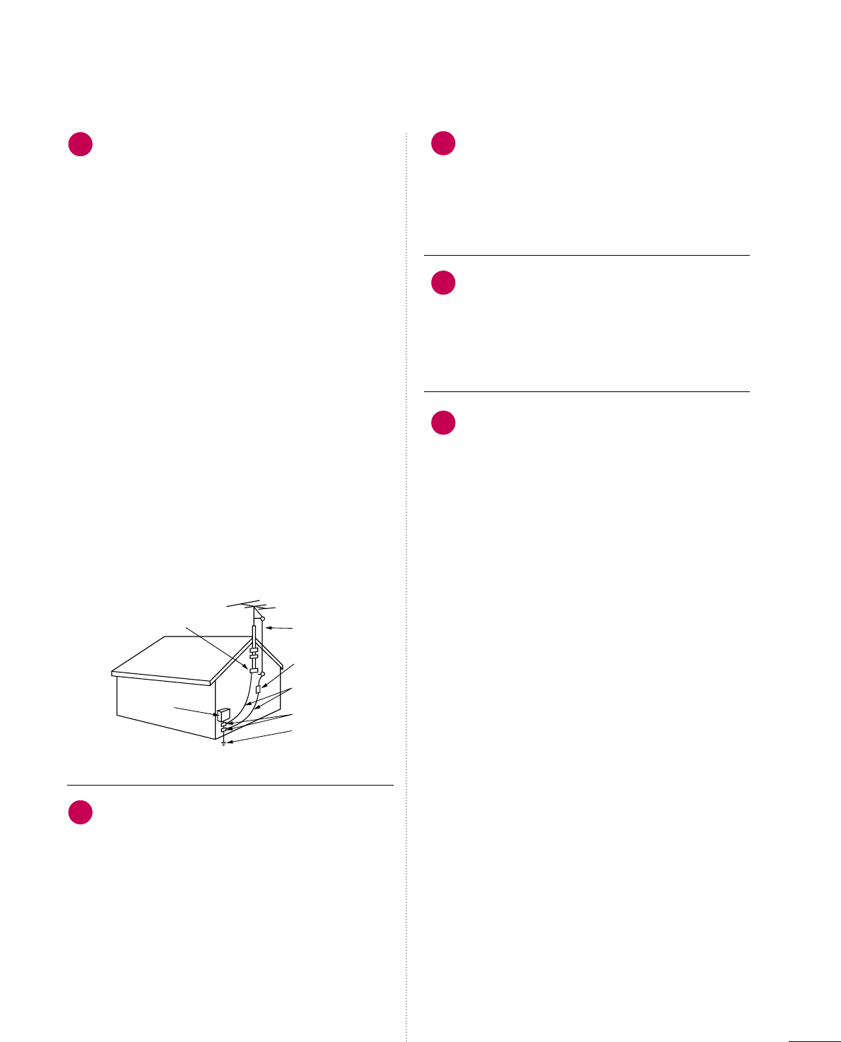
AANNTTEENNNNAASS
OOuuttddoooorr aanntteennnnaa ggrroouunnddiinngg
If an outdoor antenna is installed, follow the
precautions below. An outdoor antenna system
should not be located in the vicinity of
overhead power lines or other electric light or
power circuits, or where it can come in contact
with such power lines or circuits as death or
serious injury can occur.
Be sure the antenna system is grounded so as
to provide some protection against voltage
surges and built-up static charges.
Section 810 of the National Electrical Code
(NEC) in the U.S.A. provides information with
respect to proper grounding of the mast and
supporting structure, grounding of the lead-in
wire to an antenna discharge unit, size of
grounding conductors, location of antenna
discharge unit, connection to grounding
electrodes and requirements for the grounding
electrode.
AAnntteennnnaa ggrroouunnddiinngg aaccccoorrddiinngg ttoo tthhee
NNaattiioonnaall EElleeccttrriiccaall CCooddee,, AANNSSII//NNFFPPAA 7700
CClleeaanniinngg
When cleaning, unplug the power cord and
scrub gently with a soft cloth to prevent
scratching. Do not spray water or other liquids
directly on the TV as electric shock may occur.
Do not clean with chemicals such as alcohol,
thinners or benzene.
MMoovviinngg
Make sure the product is turned off,
unplugged and all cables have been removed. It
may take 2 or more people to carry larger TVs.
Do not press against or put stress on the front
panel of the TV.
VVeennttiillaattiioonn
Install your TV where there is proper ventilation.
Do not install in a confined space such as a
bookcase. Do not cover the product with cloth
or other materials (e.g.) plastic while plugged
in. Do not install in excessively dusty places.
If you smell smoke or other odors coming from
the TV or hear strange sounds, unplug the
power cord contact an authorized service center.
22
20
23
24
20
Antenna Lead in Wire
Antenna Discharge Unit
(NEC Section 810-20)
Grounding Conductor
(NEC Section 810-21)
Ground Clamps
Power Service Grounding
Electrode System (NEC
Art 250, Part H)
Ground Clamp
Electric Service
Equipment
NEC: National Electrical Code

6
CONTENTS
WARNING / CAUTION
. . . . . . . . . . . . . . . . . . . . . . . . . . . . 2
SAFETY INSTRUCTIONS
. . . . . . . . . . . . . . . . . . . . . . . . . . 3
FEATURE OF THIS TV
. . . . . . . . . . . . . . . . . . . . . . . . . . . . . . . 8
PREPARATION
Accessories . . . . . . . . . . . . . . . . . . . . . . . . . . . . . . . . . . . . . . . . . . . . . . . . . . . . . . 9
Front Panel Information . . . . . . . . . . . . . . . . . . . . . . . . . . . . . . . . . . . 10
Back Panel Information . . . . . . . . . . . . . . . . . . . . . . . . . . . . . . . . . . . . 12
Stand Instruction . . . . . . . . . . . . . . . . . . . . . . . . . . . . . . . . . . . . . . . . . . . . . 14
VESA Wall Mounting . . . . . . . . . . . . . . . . . . . . . . . . . . . . . . . . . . . . . . . . 18
Desktop Pedestal Installation . . . . . . . . . . . . . . . . . . . . . . . . . . . 19
Swivel Stand . . . . . . . . . . . . . . . . . . . . . . . . . . . . . . . . . . . . . . . . . . . . . . . . . . . . 19
Cable Management . . . . . . . . . . . . . . . . . . . . . . . . . . . . . . . . . . . . . . . . . 20
Attaching the TV to a Desk . . . . . . . . . . . . . . . . . . . . . . . . . . . . . . 22
Securing the TV to the wall to prevent falling when
the TV is used on a stand . . . . . . . . . . . . . . . . . . . . . . . . . . . . . . . . 23
Antenna or Cable Connection . . . . . . . . . . . . . . . . . . . . . . . . . . 24
EXTERNAL EQUIPMENT SETUP
HD Receiver Setup . . . . . . . . . . . . . . . . . . . . . . . . . . . . . . . . . . . . . . . . . 25
DVD Setup . . . . . . . . . . . . . . . . . . . . . . . . . . . . . . . . . . . . . . . . . . . . . . . . . . . . . 28
VCR Setup . . . . . . . . . . . . . . . . . . . . . . . . . . . . . . . . . . . . . . . . . . . . . . . . . . . . . 31
Other A/V Source Setup . . . . . . . . . . . . . . . . . . . . . . . . . . . . . . . . . 34
PC Setup . . . . . . . . . . . . . . . . . . . . . . . . . . . . . . . . . . . . . . . . . . . . . . . . . . . . . . . . 35
USB Connection . . . . . . . . . . . . . . . . . . . . . . . . . . . . . . . . . . . . . . . . . . . . . 42
Audio Out Connection . . . . . . . . . . . . . . . . . . . . . . . . . . . . . . . . . . . 43
WATCHING TV / CHANNEL CONTROL
Remote Control Functions . . . . . . . . . . . . . . . . . . . . . . . . . . . . . . . 44
Turning On the TV . . . . . . . . . . . . . . . . . . . . . . . . . . . . . . . . . . . . . . . . . . 46
Channel Selection . . . . . . . . . . . . . . . . . . . . . . . . . . . . . . . . . . . . . . . . . . . 46
Volume Adjustment . . . . . . . . . . . . . . . . . . . . . . . . . . . . . . . . . . . . . . . . . 46
Quick Menu . . . . . . . . . . . . . . . . . . . . . . . . . . . . . . . . . . . . . . . . . . . . . . . . . . . . 47
Initial Setting . . . . . . . . . . . . . . . . . . . . . . . . . . . . . . . . . . . . . . . . . . . . . . . . . . 48
On-Screen Menus Selection . . . . . . . . . . . . . . . . . . . . . . . . . . . . 50
Channel Setup
- Auto Scan (Auto Tuning) . . . . . . . . . . . . . . . . . . . . . . . . . . . 52
- Add / Delete Channel (Manual Tuning) . . . . . . 53
- Channel Editing . . . . . . . . . . . . . . . . . . . . . . . . . . . . . . . . . . . . . . . . 54
Input List . . . . . . . . . . . . . . . . . . . . . . . . . . . . . . . . . . . . . . . . . . . . . . . . . . . . . . . . 55
Input Label . . . . . . . . . . . . . . . . . . . . . . . . . . . . . . . . . . . . . . . . . . . . . . . . . . . . . 56
AV Mode . . . . . . . . . . . . . . . . . . . . . . . . . . . . . . . . . . . . . . . . . . . . . . . . . . . . . . . . 57
SIMPLINK . . . . . . . . . . . . . . . . . . . . . . . . . . . . . . . . . . . . . . . . . . . . . . . . . . . . . . . 58
USB
Entry Modes . . . . . . . . . . . . . . . . . . . . . . . . . . . . . . . . . . . . . . . . . . . . . . . . . . . 60
Photo List . . . . . . . . . . . . . . . . . . . . . . . . . . . . . . . . . . . . . . . . . . . . . . . . . . . . . . . 61
Music List . . . . . . . . . . . . . . . . . . . . . . . . . . . . . . . . . . . . . . . . . . . . . . . . . . . . . . . 65
PICTURE CONTROL
Picture Size (Aspect Ratio) Control . . . . . . . . . . . . . . . . . . 68
Preset Picture Settings
- Picture Mode - Preset . . . . . . . . . . . . . . . . . . . . . . . . . . . . . . . 70
- Color Tone - Preset . . . . . . . . . . . . . . . . . . . . . . . . . . . . . . . . . . . 71
Manual Picture Adjustment
- Picture Mode - User Mode . . . . . . . . . . . . . . . . . . . . . . . . 72
- Picture Mode - Expert Control . . . . . . . . . . . . . . . . . . 73
Picture Improvement Technology . . . . . . . . . . . . . . . . . . . . . 74
Advanced Control - Black (Darkness) Level . . . . . . . 75
Advanced Control - Eye Care . . . . . . . . . . . . . . . . . . . . . . . . . . . 76
Advanced Control - Real Cinema/Film Mode . . . . . 77
Picture Reset . . . . . . . . . . . . . . . . . . . . . . . . . . . . . . . . . . . . . . . . . . . . . . . . . . 78
Power Indicator . . . . . . . . . . . . . . . . . . . . . . . . . . . . . . . . . . . . . . . . . . . . . . 79
Image Sticking Minimization (ISM) Method . . . . . . 80
Power Saving Picture Mode . . . . . . . . . . . . . . . . . . . . . . . . . . . . . . 81

7
SOUND & LANGUAGE CONTROL
Auto Volume Leveler (Auto Volume) . . . . . . . . . . . . . . . . . 82
Preset Sound Settings (Sound Mode) . . . . . . . . . . . . . . 83
Sound Setting Adjustment - User Mode . . . . . . . . . . . 84
Clear Voice . . . . . . . . . . . . . . . . . . . . . . . . . . . . . . . . . . . . . . . . . . . . . . . . . . . . . 85
Balance . . . . . . . . . . . . . . . . . . . . . . . . . . . . . . . . . . . . . . . . . . . . . . . . . . . . . . . . . . 86
TV Speakers On/Off Setup . . . . . . . . . . . . . . . . . . . . . . . . . . . . . . 87
Audio Reset . . . . . . . . . . . . . . . . . . . . . . . . . . . . . . . . . . . . . . . . . . . . . . . . . . . 88
Stereo/SAP Broadcast Setup . . . . . . . . . . . . . . . . . . . . . . . . . . . 89
Audio Language . . . . . . . . . . . . . . . . . . . . . . . . . . . . . . . . . . . . . . . . . . . . . . 90
On-Screen Menus Language Selection . . . . . . . . . . . . . . 91
Caption Mode
- Analog Broadcasting System Captions . . . . . . . 92
- Digital Broadcasting System Captions . . . . . . . . 93
- Caption Option . . . . . . . . . . . . . . . . . . . . . . . . . . . . . . . . . . . . . . . 94
TIME SETTING
Clock Setting
- Auto Clock Setup . . . . . . . . . . . . . . . . . . . . . . . . . . . . . . . . . . . . 95
- Manual Clock Setup . . . . . . . . . . . . . . . . . . . . . . . . . . . . . . . . . 96
Auto On/Off Time Setting . . . . . . . . . . . . . . . . . . . . . . . . . . . . . . 97
Sleep Timer Setting . . . . . . . . . . . . . . . . . . . . . . . . . . . . . . . . . . . . . . . . . 98
Auto Shut-off Setting . . . . . . . . . . . . . . . . . . . . . . . . . . . . . . . . . . . . . . 99
PARENTAL CONTROL / RATINGS
Set Password & Lock System . . . . . . . . . . . . . . . . . . . . . . . . . 10 0
Channel Blocking . . . . . . . . . . . . . . . . . . . . . . . . . . . . . . . . . . . . . . . . . . . 103
Movie & TV Rating . . . . . . . . . . . . . . . . . . . . . . . . . . . . . . . . . . . . . . . . 10 4
Downloadable Rating . . . . . . . . . . . . . . . . . . . . . . . . . . . . . . . . . . . . . 10 9
External Input Blocking . . . . . . . . . . . . . . . . . . . . . . . . . . . . . . . . . . . 110
Key lock . . . . . . . . . . . . . . . . . . . . . . . . . . . . . . . . . . . . . . . . . . . . . . . . . . . . . . . . . 111
APPENDIX
Troubleshooting . . . . . . . . . . . . . . . . . . . . . . . . . . . . . . . . . . . . . . . . . . . . . 112
Maintenance . . . . . . . . . . . . . . . . . . . . . . . . . . . . . . . . . . . . . . . . . . . . . . . . . . 114
Product Specifications . . . . . . . . . . . . . . . . . . . . . . . . . . . . . . . . . . . . 115
Programming the Remote Control . . . . . . . . . . . . . . . . . . 116
IR Codes . . . . . . . . . . . . . . . . . . . . . . . . . . . . . . . . . . . . . . . . . . . . . . . . . . . . . .119
External Control Through RS-232C . . . . . . . . . . . . . . . . .121

8
FEATURE OF THIS TV
is a trademark of SRS Labs, Inc.
TruSurround XT technology is incorporated under
license from SRS Labs, Inc.
Manufactured under license from Dolby Laboratories.
“
Dolby
“and the double-D symbol are trademarks of
Dolby Laboratories.
FOR LCD TV
■
If the TV feels cold to the touch, there may be a small “flicker” when it is turned on. This is normal, there is
nothing wrong with TV.
■
Some minute dot defects may be visible on the screen, appearing as tiny red, green, or blue spots. However, they
have no adverse effect on the monitor's performance.
■
Avoid touching the LCD screen or holding your finger(s) against it for long periods of time. Doing so may produce
some temporary distortion effects on the screen.
On Disposal (Only Hg lamp used LCD TV)
The fluorescent lamp used in this product contains a small amount of mercury. Do not dispose of this product with
general household waste. Disposal of this product must be carried out in accordance to the regulations of your local
authority.
PREPARATION
9
PREPARATION
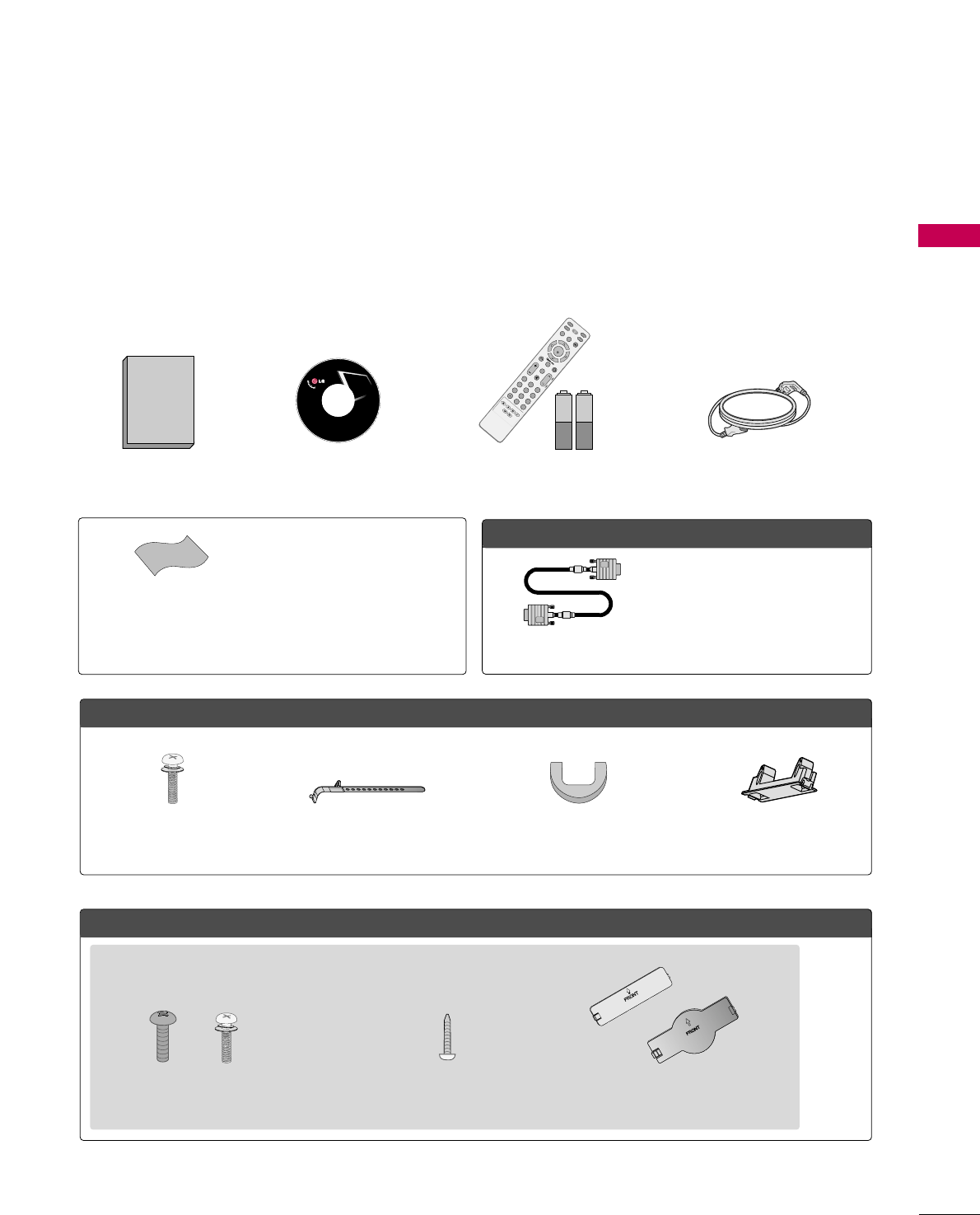
ACCESSORIES
Ensure that the following accessories are included with your TV. If an accessory is missing, please contact the
dealer where you purchased the TV.
The accessories included may differ from the images below.
OOppttiioonn EExxttrraass
FFoorr LLCCDD TTVV mmooddeellss
FFoorr PPllaassmmaa TTVV mmooddeellss
* Wipe spots on the exterior only with
the polishing cloth.
* Do not wipe roughly when removing
stain. Excessive pressure may cause
scratch or discoloration.
Polishing Cloth
(This feature is not available
for all models.)
Copyright© 2007 LGE,
All Rights Reserved.
D-sub 15 pin Cable
1.5V 1.5V
Owner’s Manual Power Cord
Remote Control,
Batteries
INPUT
FAV
MUTE
TV
STB
POWER
Q. MENUMENU
AV MODE
RETURN
ENTER
VOLCH
123
456
78
0
9
FLASHBK
P
A
G
E
DVD
VCR
CD Manual
When using the VGA (D-sub 15 pin
cable) PC connection, the user
must use shielded signal interface
cables with ferrite cores to maintain
standards compliance.
Bolts for stand assembly
(Refer to P.16)
(Only 32/37/42LG30DC)
Protection Cover
Screw for stand fixing
(Refer to P.22)
(Only 32LG30DC)
x 4 x 4
Cable Management Clip Protection Cover
or
Cable Holder
Bolts for stand assembly
(Refer to P.14)
x 4
PREPARATION
10
PREPARATION
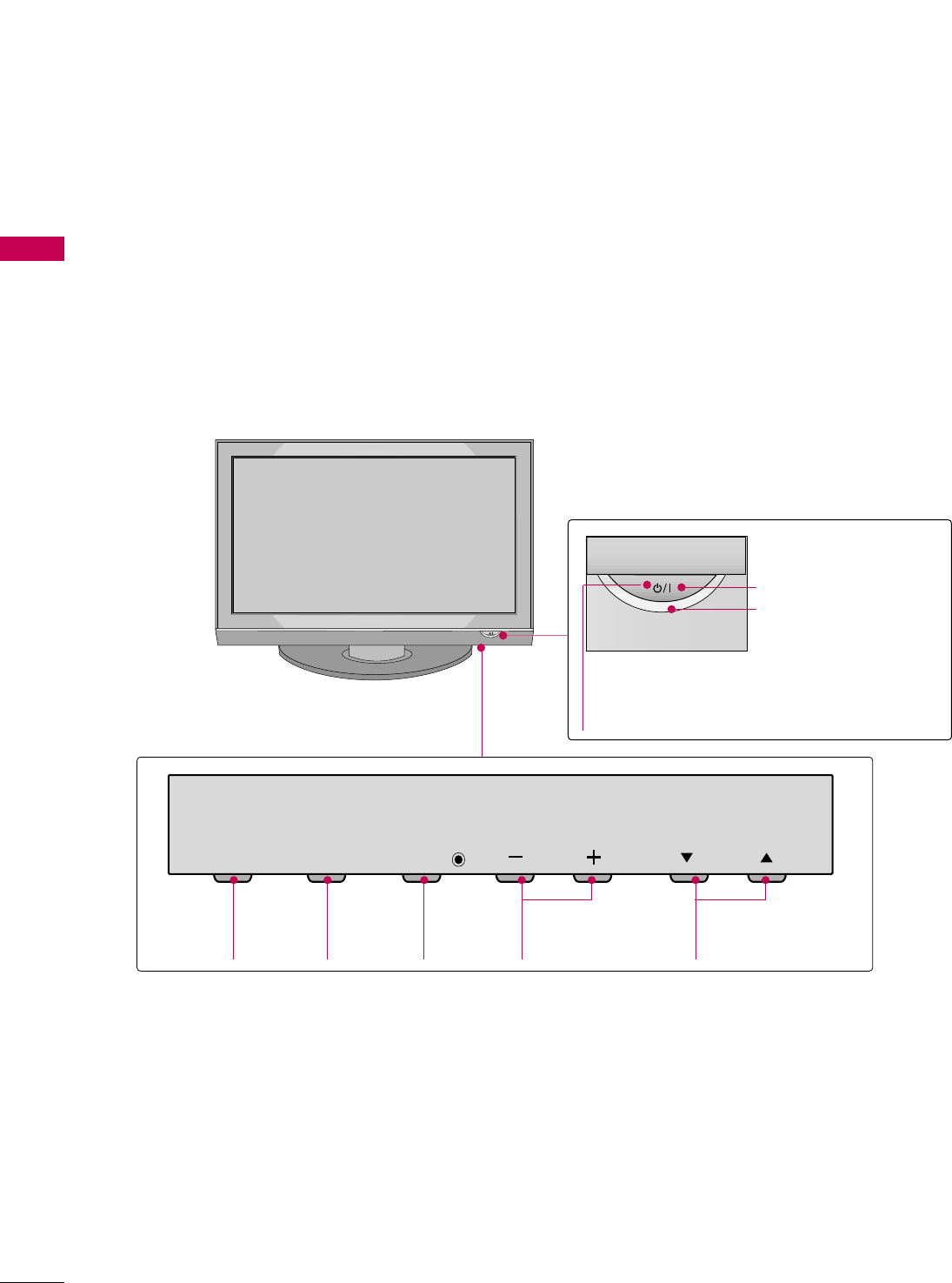
FRONT PANEL INFORMATION
■
Image shown may differ from your TV.
■
NOTE: If your TV has a protection tape attached, remove the tape.
And then wipe the TV with a cloth (If a polishing cloth is included with your TV, use it).
Plasma TV Models
CH
VOL
MENU
INPUT ENTER
CH
VOL
MENU
INPUT ENTER
INPUT
Button
MENU
Button
ENTER
Button
VOLUME
(-, +) Buttons
CHANNEL
(EE,DD)Buttons
CH
VOL
MENU
INPUT ENTER
Remote Control Sensor
POWER Button
Power/Standby Indicator
Illuminates red in standby mode.
Illuminates blue when the TV is switched on.
PREPARATION
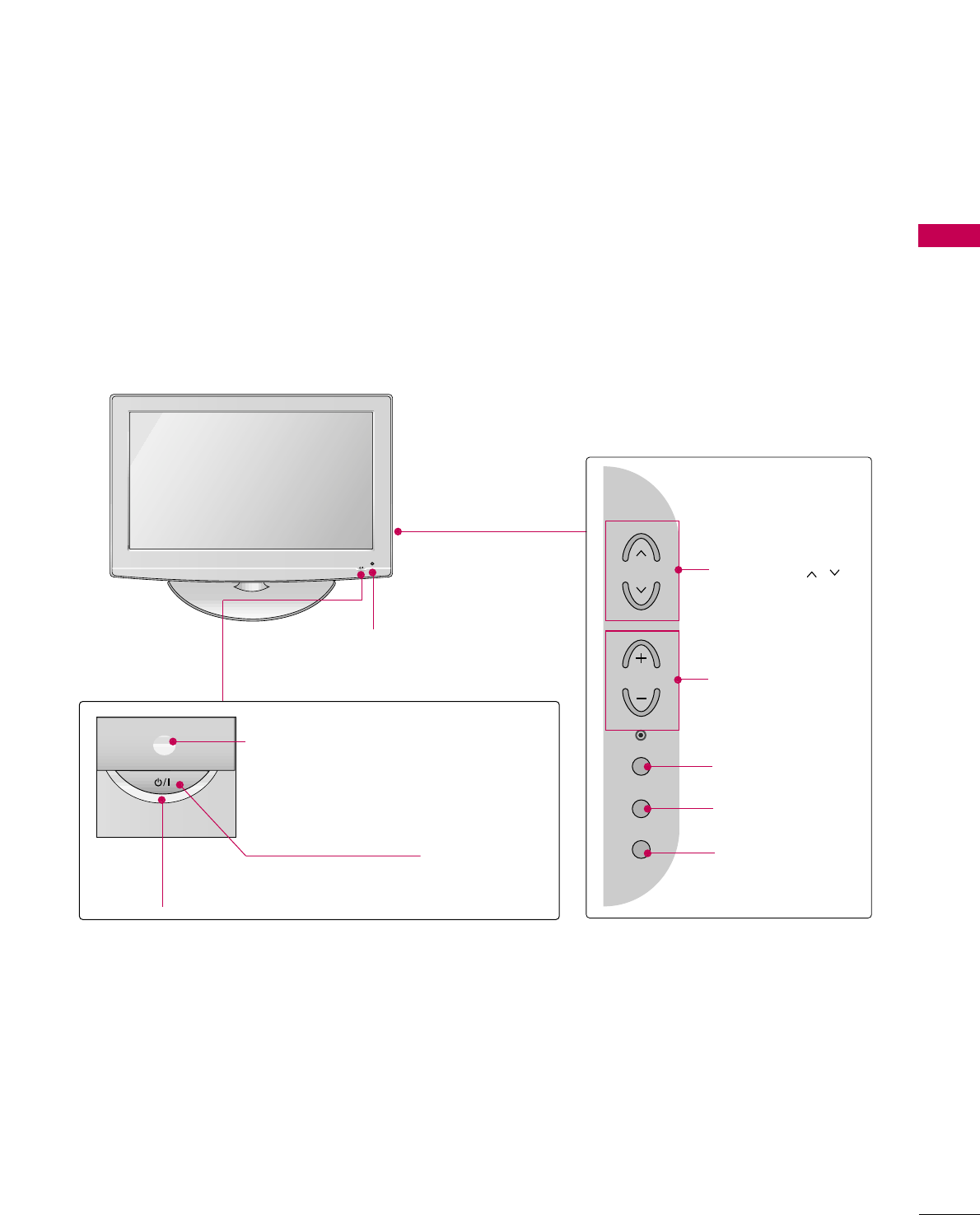
11
LCD TV Models
POWER Button
Power/Standby Indicator
Illuminates red in standby mode.
Illuminates blue when the set is switched on.
(Can be adjusted using PPoowweerr IInnddiiccaattoorrin
the OPTION menu. GGpp..7799)
CH
VOL
MENU
INPUT
ENTER
CHANNEL ( , )
Buttons
VOLUME (+, -)
Buttons
ENTER Button
MENU Button
INPUT Button
Intelligent Sensor (Except 32/37/42LG30DC)
Adjusts picture according to the surrounding
conditions
Remote Control Sensor
PREPARATION
12
PREPARATION
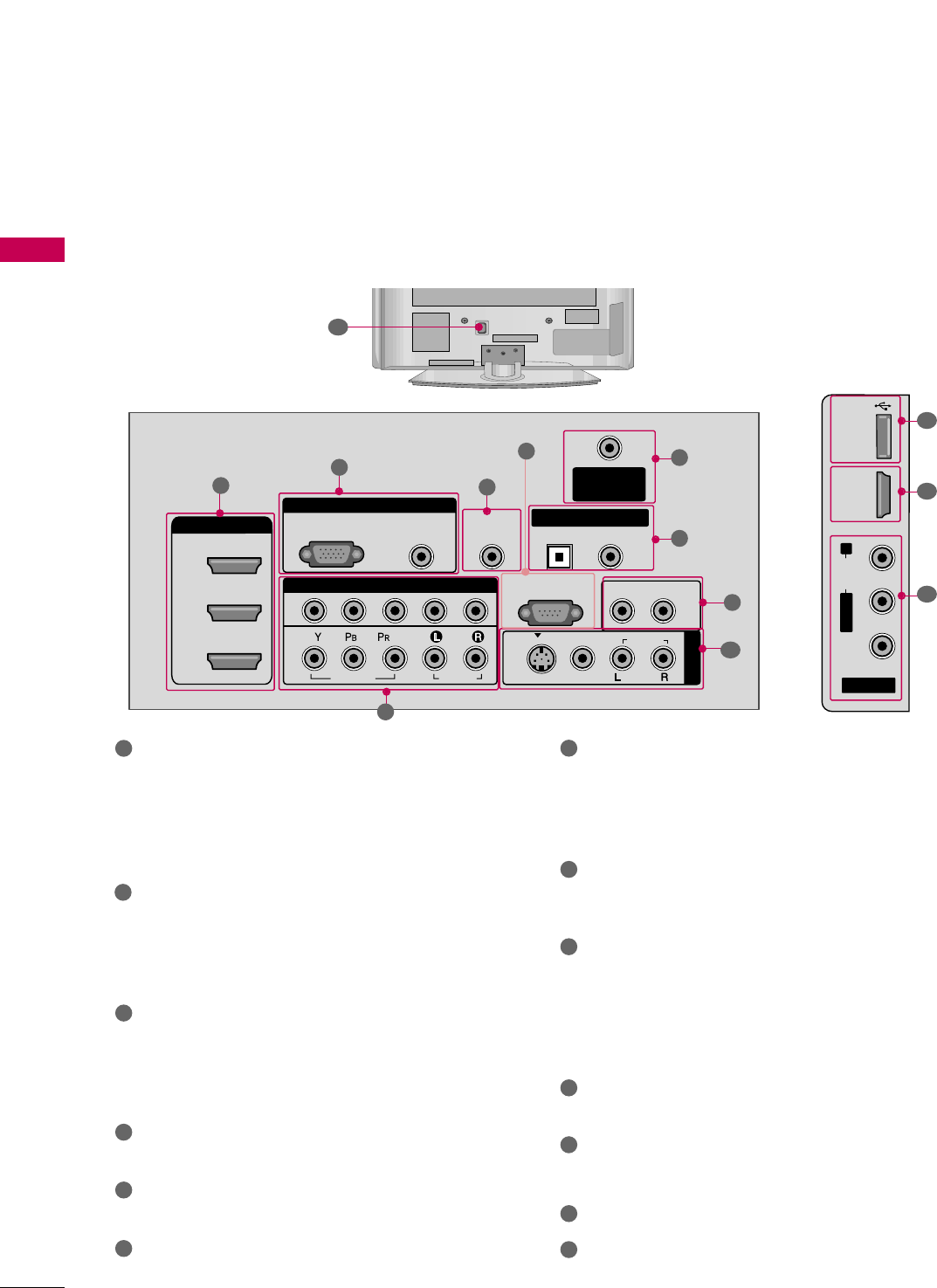
BACK PANEL INFORMATION
Plasma TV Models
■
Image shown may differ from your TV.
R
( )
13
AV IN 2
L/MONO
R
AUDIO
VIDEO
USB IN
HDMI IN 4
( )
9
10
1
R
RGB IN
COMPONENT IN
AUDIO
(RGB/DVI)
RGB(PC)
ANTENNA/
CABLE IN
1
2
RS-232C IN
(CONTROL & SERVICE)
VIDEO
AUDIO
VIDEO
AUDIO OUT
OPTICAL COAXIAL
MONO
( )
AUDIO
S-VIDEO
DIGITAL AUDIO OUT
AV IN 1
HDMI/DVI IN
3
2
1
REMOTE
CONTROL IN
1
3
4
6
7
8
2
9
5
HDMI/DVI IN, HDMI IN
Digital Connection.
Supports HD video and Digital audio. Doesn’t
support 480i.
Accepts DVI video using an adapter or HDMI to
DVI cable (not included).
COMPONENT IN
Analog Connection.
Supports HD.
Uses a red, green, and blue cable for video & red
and white for audio.
RGB (PC)
Analog PC Connection. Uses a D-sub 15 pin cable
(VGA cable).
AUDIO (RGB/DVI)
1/8” headphone jack for analog PC audio input.
REMOTE CONTROL IN PORT
For a wired remote control.
RS-232C IN (CONTROL & SERVICE) PORT
Used by third party devices.
ANTENNA/CABLE IN
Connect over-the air signals to this jack.
Connect cable signals to this jack.
DIGITAL AUDIO OUT
Digital audio output for use with amps and home
theater systems.
Includes an optical and/or coaxial connection.
Note: In standby mode, these ports do not work.
AUDIO OUT
Analog audio output for use with amps and home
theater systems.
AV (Audio/Video) IN
Analog composite connection. Supports standard
definition video only (480i).
S-VIDEO
Better quality than standard composition.
Supports standard definition video only (480i).
USB INPUT
Used for viewing photos and listening to MP3s.
USB SERVICE ONLY or RS-232C IN (SERVICE
ONLY)
Used for software updates.
RJP INTERFACE
Power Cord Socket
For operation with AC power.
Caution: Never attempt to operate the TV on DC
power.
1
2
3
4
5
6
9
10
11
12
13
7
8
PREPARATION
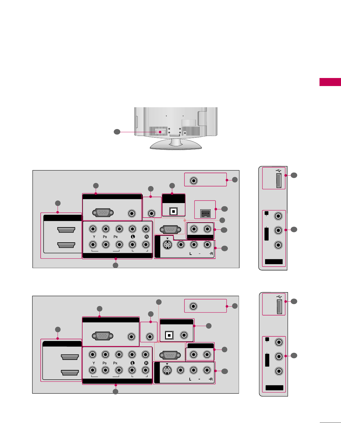
13
LCD TV Models
AV IN 2
L/MONO
R
AUDIO
VIDEO
USB IN
( )
RGB IN
COMPONENT IN
AUDIO
(RGB/DVI)
RGB(PC)
REMOTE
CONTROL IN
ANTENNA/
CABLE IN
1
2
RS-232C IN
(CONTROL & SERVICE)
VIDEO
AUDIO
OPTICAL COAXIAL
DIGITAL AUDIO OUT
AUDIO OUT
AV IN 1
R
HDMI/DVI IN
2
1
VIDEO
MONO
( )
AUDIO
S-VIDEO
1
3
4
6
7
8
2
9
9
5
RGB IN
COMPONENT IN
AUDIO
(RGB/DVI)
RGB(PC)
REMOTE
CONTROL IN
RJP
INTERFACE
ANTENNA/
CABLE IN
1
2
RS-232C IN
(CONTROL & SERVICE)
VIDEO
AUDIO
OPTICAL
AUDIO OUT
AV IN 1
R
VIDEO
MONO
( )
AUDIO
S-VIDEO
2
1
HDMI/DVI IN
DIGITAL
AUDIO OUT
1
347
6
2
8
5
10
AV IN 2
L/MONO
R
AUDIO
VIDEO
USB
SERVUCE ONLY
( )
9
11
12
47/52LG50DC
32/37/42LG30DC
R
( )
13
9
PREPARATION
14
PREPARATION
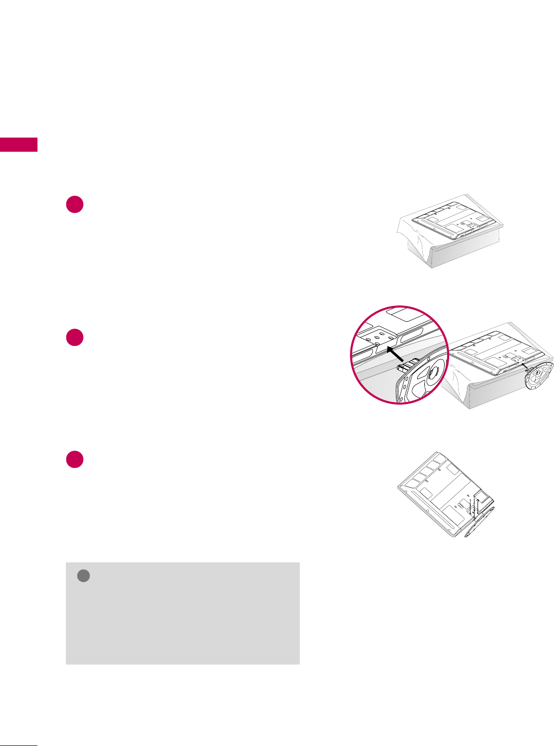
STAND INSTRUCTION
■
Image shown may differ from your TV.
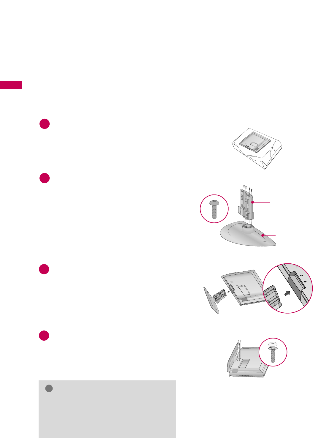
Carefully place the TV screen side down on a
cushioned surface to protect the screen from
damage.
Assemble the TV as shown.
Fix the 4 bolts securely using the holes in the
back of the TV.
1
2
3
INSTALLATION
Plasma TV models
GGWhen assembling the desk type stand, make sure
the bolt is fully tightened. (If not tightened fully,
the TV can tilt forward after the product installa-
tion). Do not over tighten.
NOTE
!
PREPARATION
15
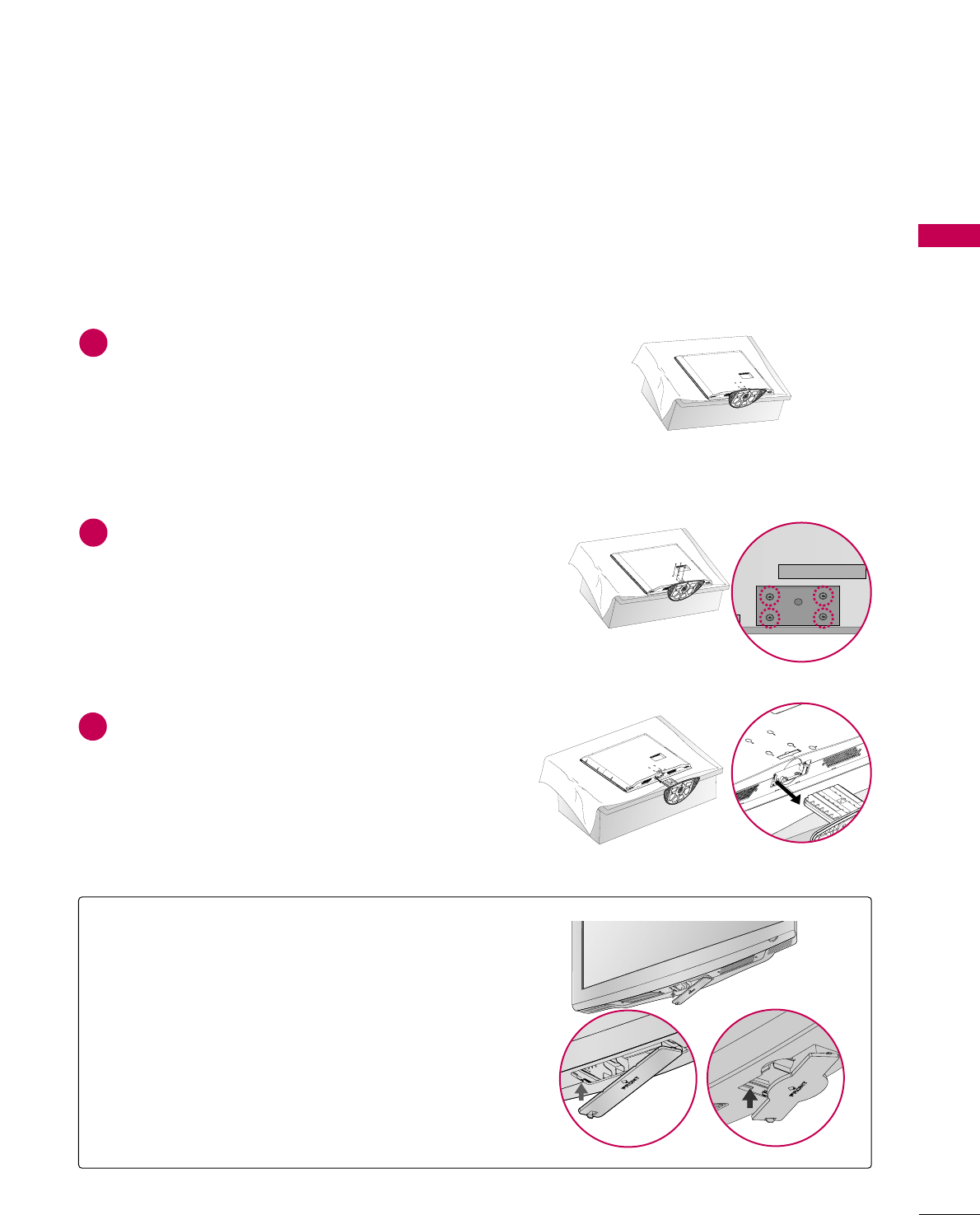
DETACHMENT
Carefully place the TV screen side down on a
cushioned surface to protect the screen from
damage.
1
Loose the bolts from TV.
2
Detach the stand from TV.
3
PROTECTION COVER
After removing the stand, install the included
pprrootteeccttiioonn ccoovveerrover the hole for the stand.
Press the PPRROOTTEECCTTIIOONN CCOOVVEERRinto the TV
until you hear it click.
PREPARATION
16
PREPARATION
■
Image shown may differ from your TV.
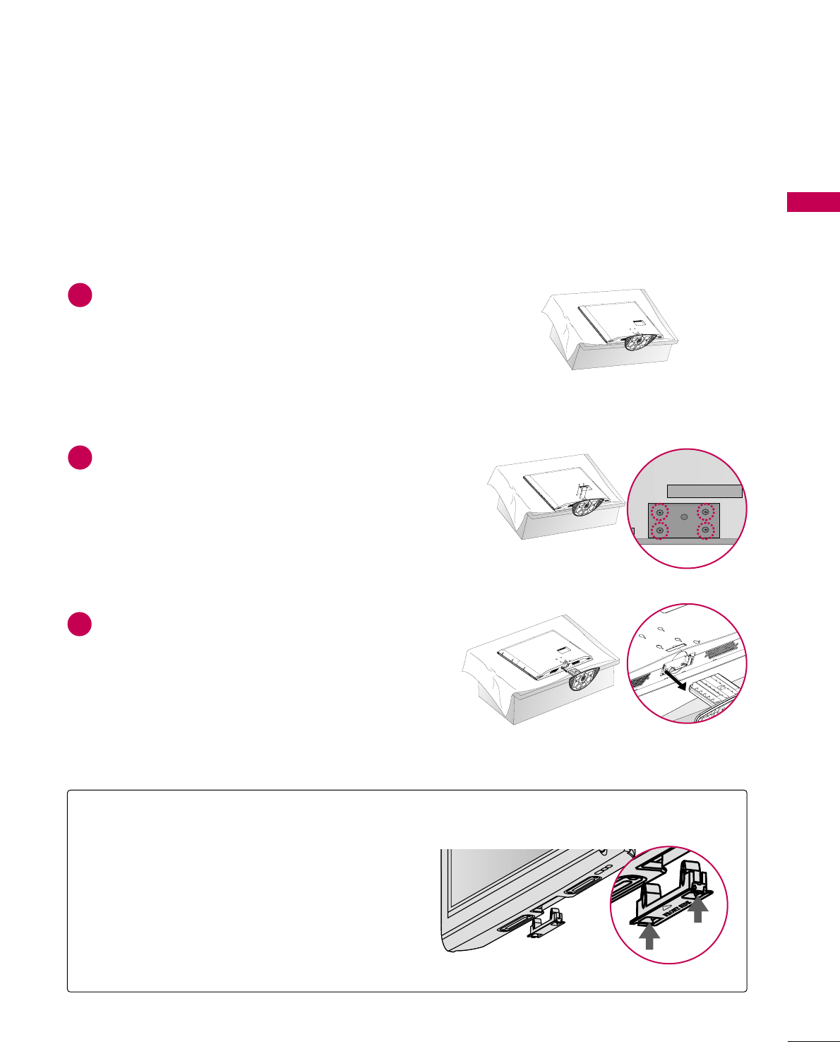
LCD TV models
Assemble the parts of the SSTTAANNDD BBOODDYY
with CCOOVVEERR BBAASSEEof the TV.
2
Assemble the TV as shown.
3
Fix the 4 bolts securely using the holes in the
back of the TV.
4
SSTTAANNDD BBOODDYY
CCOOVVEERR BBAASSEE
Carefully place the TV screen side down on a
cushioned surface to protect the screen from
damage.
1
INSTALLATION (
Except 47/52LG50DC)
GGWhen assembling the desk type stand, make sure
the bolt is fully tightened. (If not tightened fully,
the TV can tilt forward after the product installa-
tion). Do not over tighten.
NOTE
!
PREPARATION
17
DETACHMENT
Carefully place the TV screen side down on a
cushioned surface to protect the screen from
damage.
1
Loose the bolts from TV.
2
Detach the stand from TV.
3
After removing the stand, install the included
pprrootteeccttiioonn ccoovveerrover the hole for the stand.
Press the PPRROOTTEECCTTIIOONN CCOOVVEERRinto the TV
until you hear it click.
PROTECTION COVER
PREPARATION
18
PREPARATION
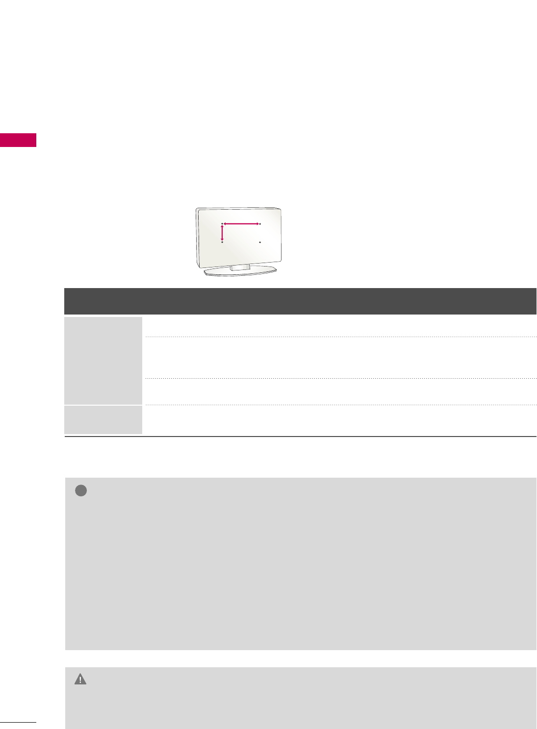
VESA WALL MOUNTING
Install your wall mount on a solid wall perpendicular to the floor. When attaching to other building materials, please
contact your nearest dealer.
If installed on a ceiling or slanted wall, it may fall and result in severe personal injury.
We recommend that you use an LG brand wall mount when mounting the TV to a wall.
LG recommends that wall mounting be performed by a qualified professional installer.
GGDo not install your wall mount kit while your TV is turned on. It may result in personal injury due to electric
shock.
CAUTION
GGScrew length needed depends on the wall mount
used. For further information, refer to the instruc-
tions included with the mount.
GGStandard dimensions for wall mount kits are shown
in the table.
GGWhen purchasing our wall mount kit, a detailed
installation manual and all parts necessary for
assembly are provided.
GGDo not use screws longer then the standard dimen-
sion, as they may cause damage to the inside to
the TV.
GGFor wall mounts that do not comply with the VESA
standard screw specifications, the length of the
screws may differ depending on their specifica-
tions.
GGDo not use screws that do not comply with the
VESA standard screw specifications.
Do not use fasten the screws too strongly, this may
damage the TV or cause the TV to a fall, leading to
personal injury. LG is not liable for these kinds of
accidents.
GGLG is not liable for TV damage or personal injury
when a non-VESA or non specified wall mount is
used or the consumer fails to follow the TV installa-
tion instructions.
NOTE
!
AA
BB
Product Model VESA
(A *B) Standard Screw Quantity
32LG30DC
37LG30DC
42LG30DC
47LG50DC
52LG50DC
42PG60C
200 * 10 0
200 * 200
800 * 400
400 * 400
M4
M6
M6
M6
4
4
4
4
LCD TV
PLASMA TV
PREPARATION
19
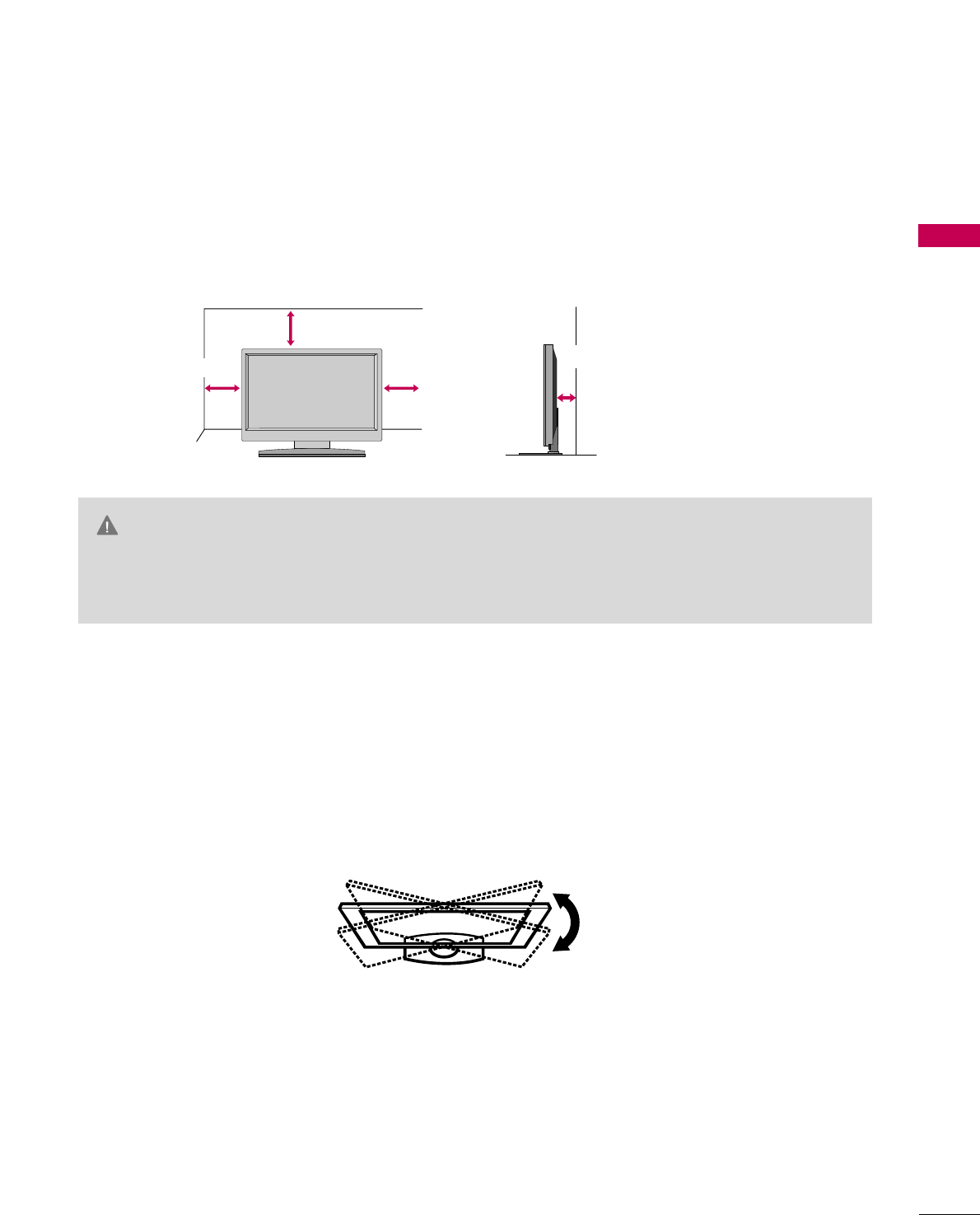
DESKTOP PEDESTAL INSTALLATION
For proper ventilation, allow a clearance of 4 inches on all four sides from the wall.
■
Image shown may differ from your TV.
4 inches
4 inches
4 inches 4 inches
SWIVEL STAND
After installing the TV, you can adjust the TV set manually to the left or right direction by 20 degrees to suit
your viewing position.
GGEnsure adequate ventilation by following the clearance recommendations.
GGDo not mount near or above any type of heat source.
CAUTION
PREPARATION
20
PREPARATION
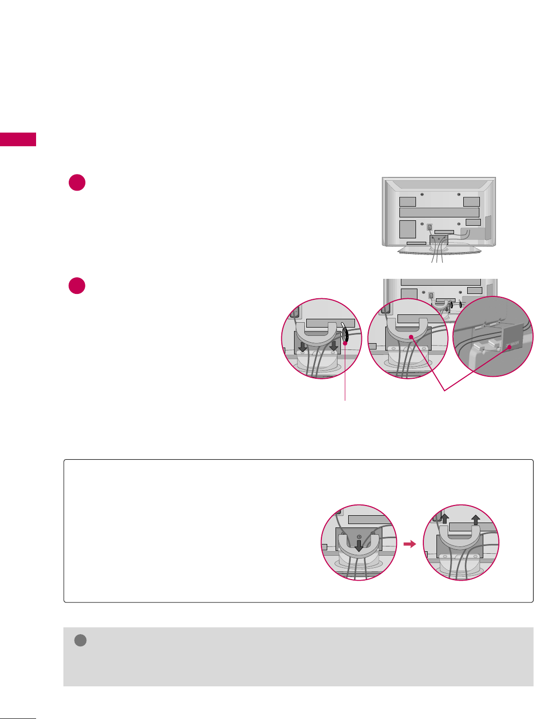
CABLE MANAGEMENT
■
Image shown may differ from your TV.
Plasma TV Model
Connect the cables as necessary.
To connect additional equipment, see the
EXTERNAL EQUIPMENT SETUP section.
Install the CABLE MANAGEMENT CLIP as
shown.
If your TV has the CABLE HOLDER, install it
as shown and bundle the cables.
1
2
GGDo not hold the CABLE MANAGEMENT CLIP when moving the TV.
- If the TV is dropped, you may be injured or the product may be broken.
NOTE
!
How to remove the CABLE MANAGEMENT CLIP
GGFirst, press the cable management. Hold the
CCAABBLLEE MMAANNAAGGEEMMEENNTT CCLLIIPPwith both
hands and pull it upward.
CABLE MANAGEMENT CLIP
CABLE HOLDER
PREPARATION
21
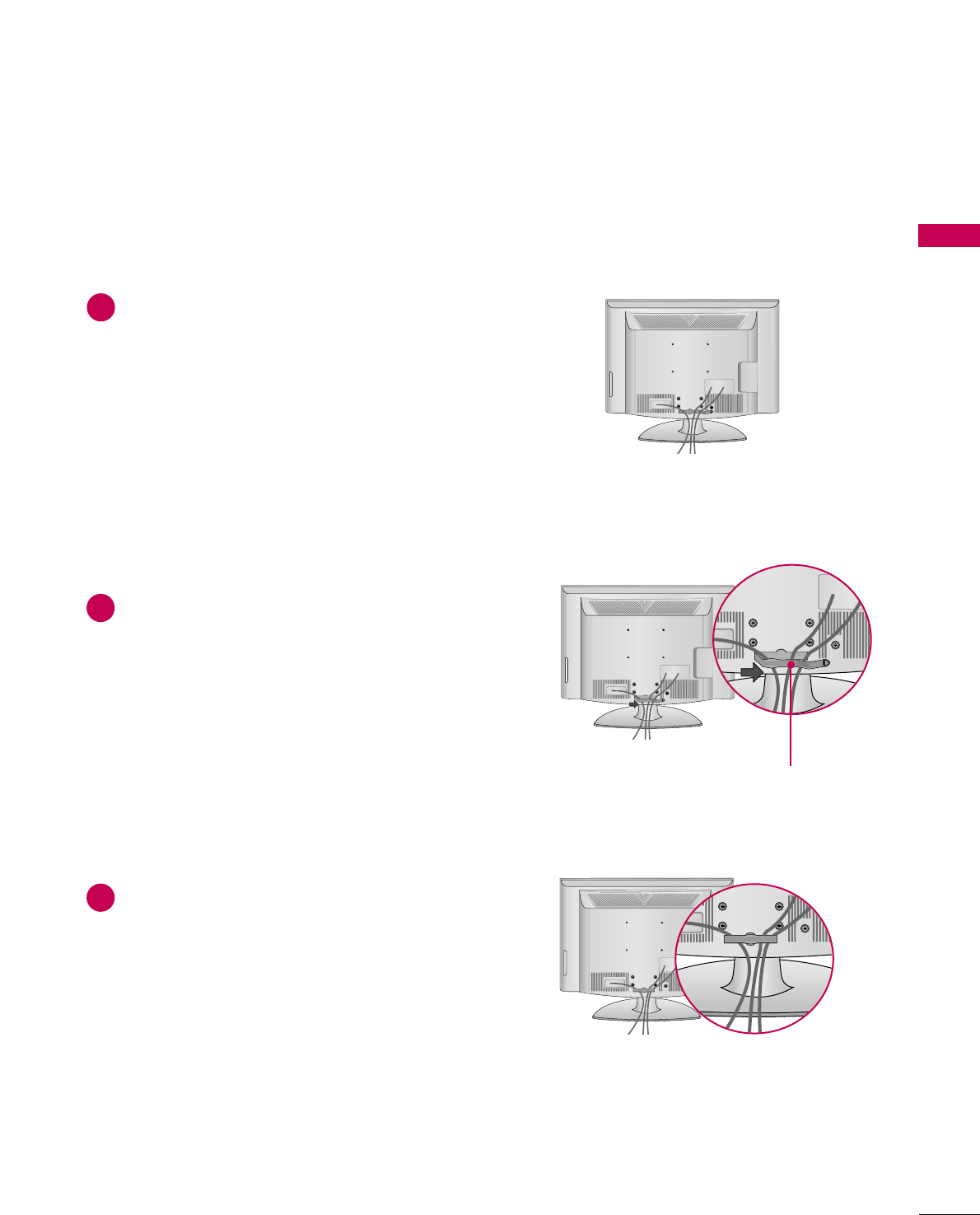
LCD TV Models
Connect the cables as necessary.
To connect additional equipment, see the
EXTERNAL EQUIPMENT SETUP section.
Install the CABLE MANAGEMENT CLIP as
shown.
Put the cables inside the CABLE MANAGE-
MENT CLIP and snap it closed.
CABLE MANAGEMENT CLIP
1
2
3
PREPARATION
22
PREPARATION
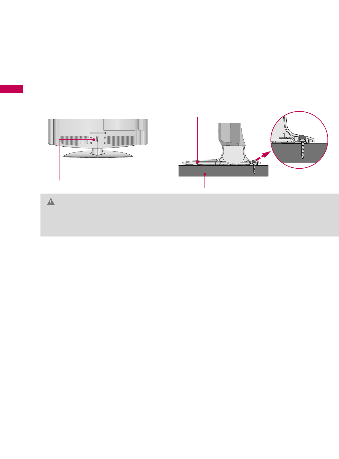
ATTACHING THE TV TO A DESK (Only 32/42LG30)
The TV must be attached to a desk so it cannot be pulled in a forward/backward direction, potentially causing
injury or damaging the product.
GGTo prevent TV from falling over, the TV should be securely attached to the floor/wall per installation
instructions. Tipping, shaking, or rocking the machine may cause injury.
WARNING
1-Screw
(provided as parts of the product)
Desk
Stand
PREPARATION
23
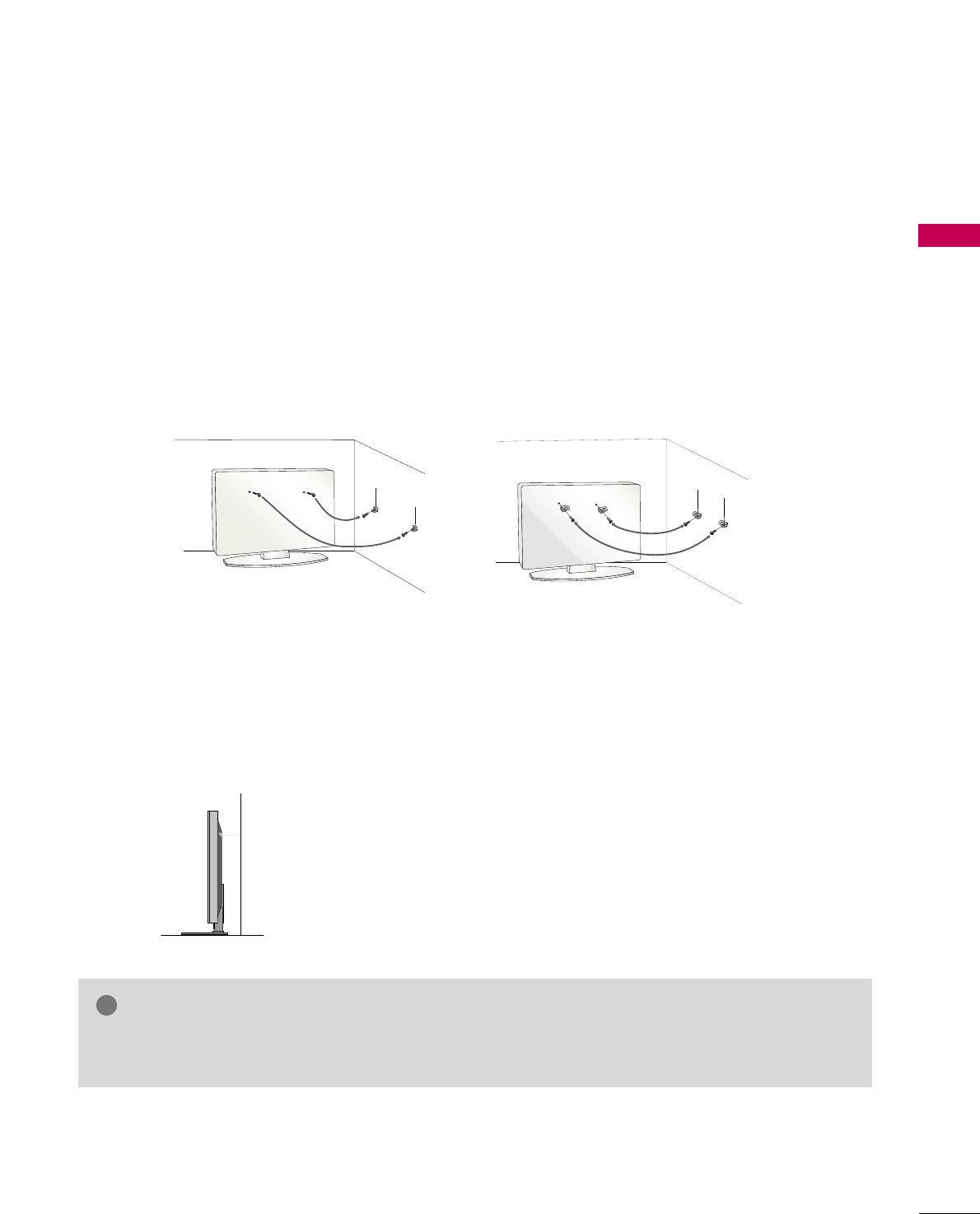
SECURING THE TV TO THE WALL TO PREVENT FALLING
WHEN THE TV IS USED ON A STAND
We recommend that you set up the TV close to a wall so it cannot fall over if pushed backwards.
Additionally, we recommend that the TV be attached to a wall so it cannot be pulled in a forward direction,
potentially causing injury or damaging the product.
Caution: Please make sure that children don’t climb on or hang from the TV.
■Insert the eye-bolts (or TV brackets and bolts) to tighten the product to the wall as shown in the picture.
*If your product has the bolts in the eye-bolts position before inserting the eye-bolts, loosen the bolts.
* Insert the eye-bolts or TV brackets/bolts and tighten them securely in the upper holes.
Secure the wall brackets with the bolts (sold separately) to the wall. Match the height of the bracket that is
mounted on the wall to the holes in the product.
Ensure the eye-bolts or brackets are tightened securely.
■Use a sturdy rope or cord (sold separately) to tie the product. It is
safer to tie the rope so it becomes horizontal between the wall and the
product.
■
You should purchase necessary components to prevent TV from falling off of the stand.
■
Image shown may differ from your TV.
GGUse a platform or cabinet strong enough and large enough to support the size and weight of the TV.
GGTo use the TV safely make sure that the height of the bracket on the wall and the one on the TV are the same.
NOTE
!
PREPARATION
24
PREPARATION
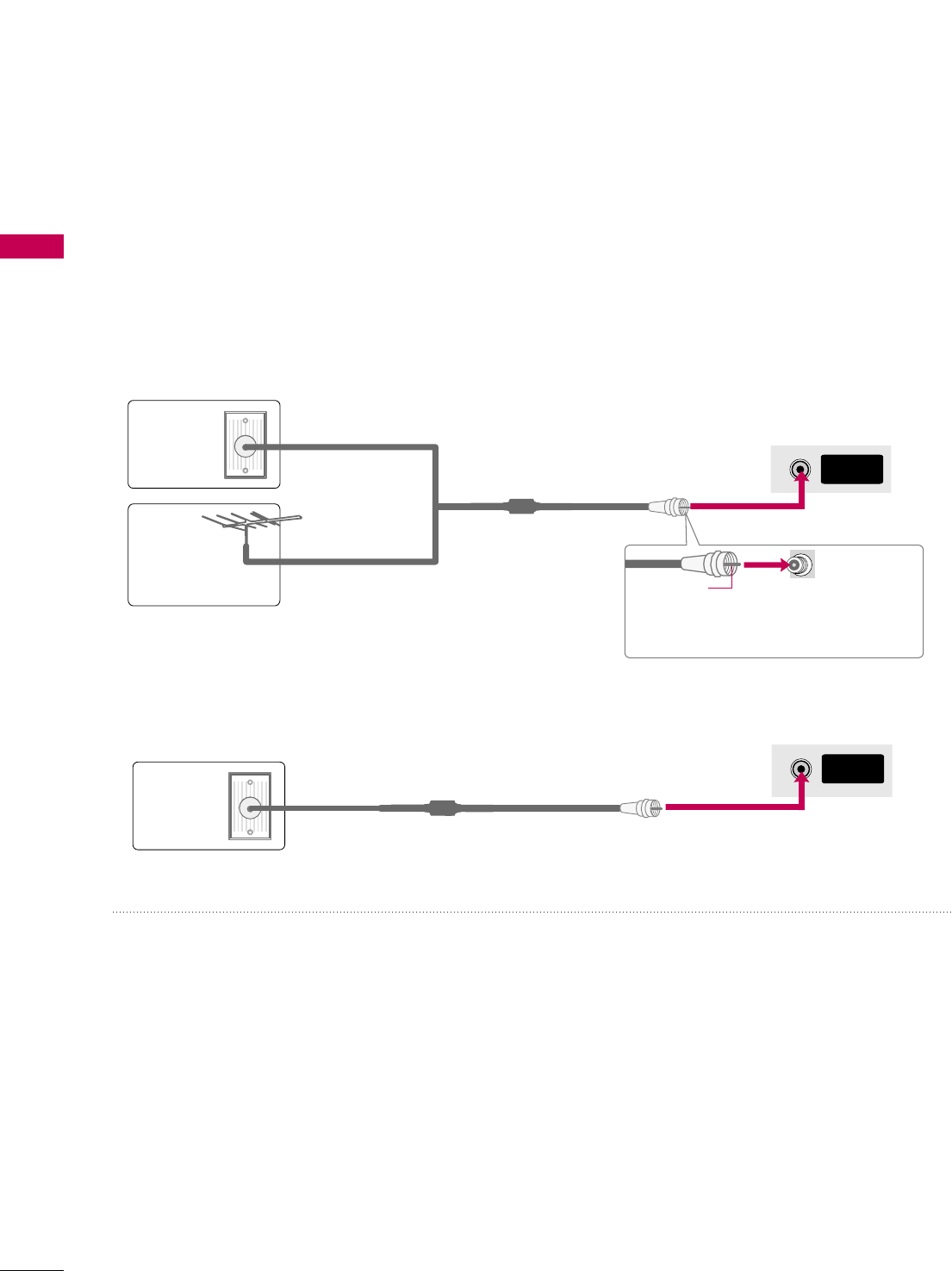
ANTENNA OR CABLE CONNECTION
1. Antenna (Analog or Digital)
Wall Antenna Socket or Outdoor Antenna without a Cable Box
Connection.
For optimum picture quality, adjust the antenna direction if needed.
2. Cable
Wall
Antenna
Socket
Outdoor
Antenna
(VHF, UHF)
Cable TV
Wall Jack
Multi-family Dwellings/Apartments
(Connect to wall antenna socket)
RF Coaxial Wire (75 ohm)
RF Coaxial Wire (75 ohm)
Single-family Dwellings /Houses
(Connect to wall jack for outdoor antenna)
Be careful not to bend the copper wire
when connecting the antenna.
Copper Wire
■To improve the picture quality in a poor signal area, please purchase a signal amplifier and install properly.
■If the antenna needs to be split for two TV’s, install a 2-Way Signal Splitter.
■If the antenna is not installed properly, contact your dealer for assistance.
ANTENNA/
CABLE IN
( )
R
ANTENNA/
CABLE IN
( )
R
■To prevent damage do not connect to the power outlet until all connections are made between the devices.
EXTERNAL EQUIPMENT SETUP
25
EXTERNAL EQUIPMENT SETUP
HD RECEIVER SETUP
This TV can receive digital over-the-air/digital cable signals without an external digital set-top box. However, if
you do receive digital signals from a digital set-top box or other digital external device.
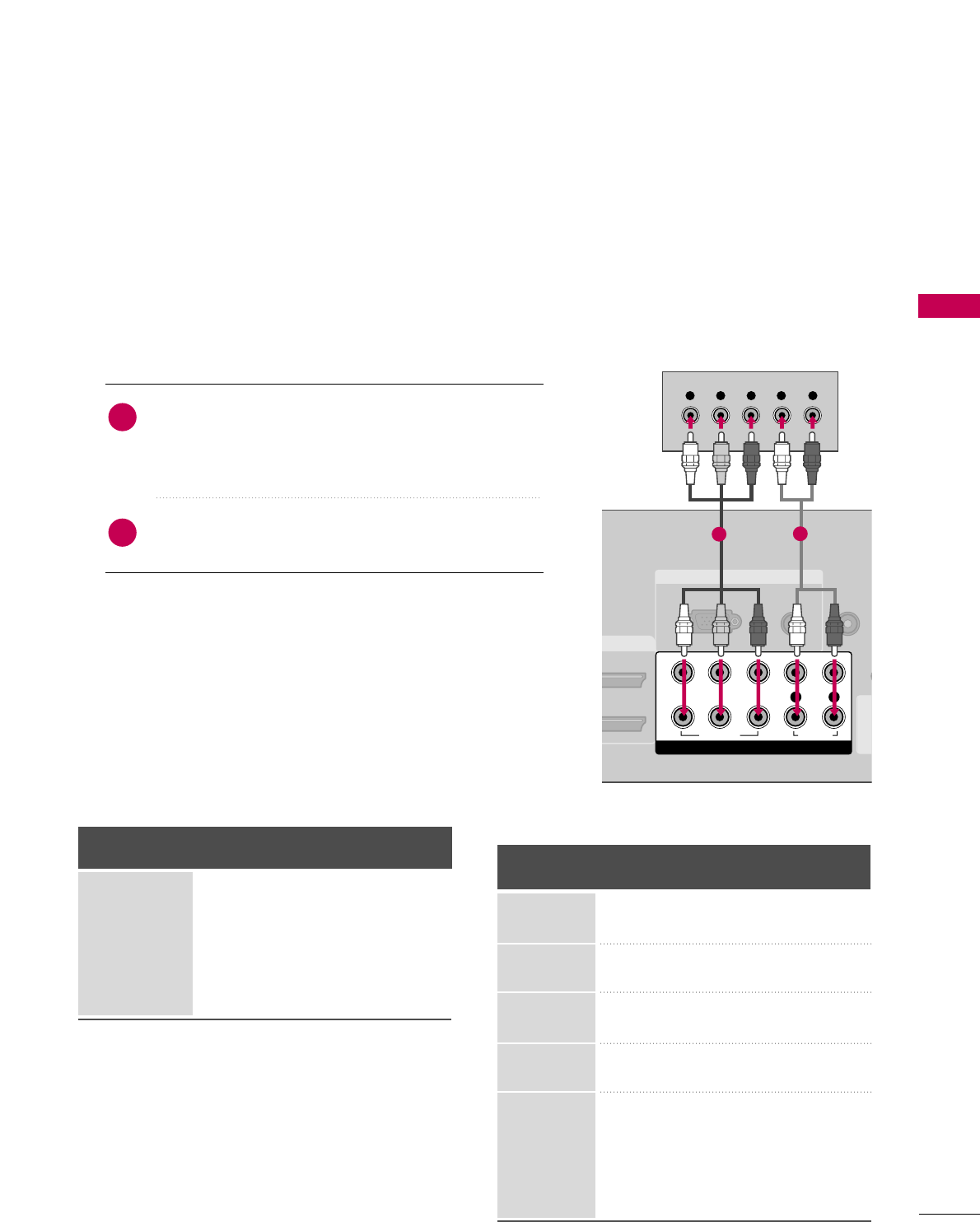
Component Connection
1. How to connect
Connect the video outputs (Y, PB, PR)of the digital set-
top box to the CCOOMMPPOONNEENNTT IINN VVIIDDEEOO 11jacks on
the TV. Match the jack colors (Y = green, PB= blue, and
PR= red).
Connect the audio output of the digital set-top box to
the CCOOMMPPOONNEENNTT IINN AAUUDDIIOO 11jacks on the TV.
2
1
2. How to use
■Turn on the digital set-top box.
(Refer to the owner’s manual for the digital set-top box. operation)
■Select the CCoommppoonneenntt11input source on the TV using
the IINNPPUUTTbutton on the remote control.
■If connected to CCOOMMPPOONNEENNTT IINN22input, select the
CCoommppoonneenntt 22input source on the TV.
■To prevent the equipment damage, never plug in any power cords until you have finished connecting all equipment.
■
Image shown may differ from your TV.
Y, CB/PB, CR/PR
Supported Resolutions
Horizontal Vertical
Frequency(KHz)Frequency(Hz)
15.73 59.94
15.73 60.00
31.47 59.94
31.50 60.00
44.96 59.94
45.00 60.00
33.72 59.94
33.75 60.00
26.97 23.976
27.00 24.00
33.71 29.97
33.75 30.00
67.432 59.94
67.50 60.00
Resolution
720x480i
720x480p
1280x720p
1920x1080i
1920x1080p
Signal
480i
480p
720p
108 0 i
108 0 p
Component
Yes
Yes
Yes
Yes
Yes
HDMI
No
Yes
Yes
Yes
Yes
RGB IN
AUDIO
(RGB/DVI)
RGB(PC)
REMOTE
CONTROL IN
(CO
AV IN 1
DVI IN
COMPONENT IN
1
2
VIDEO
LYP
BPRR
AUDIO
Y L RPBPR
12
EXTERNAL EQUIPMENT SETUP
26
EXTERNAL EQUIPMENT SETUP
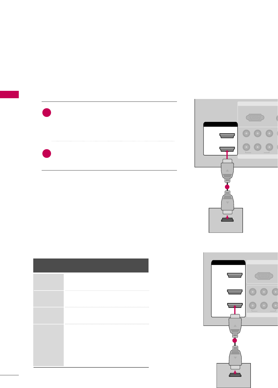
HDMI Connection
LCD TV: Connect the digital set-top box to
HHDDMMII//DDVVII IINN11or 22jack on the TV.
Plasma TV: Connect the digital set-top box to
HHDDMMII//DDVVII IINN11, 22, 33, or 44 jack on the TV.
No separate audio connection is necessary.
HDMI supports both audio and video.
1. How to connect
2. How to use
■Turn on the digital set-top box.
(Refer to the owner’s manual for the digital set-top box.)
■LCD TV: Select the HHDDMMII11or HHDDMMII22 input source on the
TV using the IINNPPUUTTbutton on the remote control.
Plasma TV: Select the HHDDMMII11, HHDDMMII22, HHDDMMII33, or HHDDMMII44
input source on the TV using the IINNPPUUTTbutton on the
remote control.
2
1
HDMI-DTV
Horizontal Vertical
Frequency(KHz)Frequency(Hz)
31.47 59.94
31.50 60.00
44.96 59.94
45.00 60.00
33.72 59.94
33.75 60.00
26.97 23.976
27.00 24.00
33.71 29.97
33.75 30.00
67.432 59.939
67.50 60.00
Resolution
720x480p
1280x720p
1920x1080i
1920x1080p
RGB IN
COMPONENT
A
(RG
RGB(PC)
1
2
VIDEO
YP
BPR
HDMI/DVI IN
2
1
HDMI-DTV OUTPUT
LCD TV
RGB IN
COMPON
RGB(PC)
VIDEO
YP
BPR
2
3
( )
HDMI/DVI IN
1
HDMI-DTV OUTPUT
( )
1
1
Plasma TV
EXTERNAL EQUIPMENT SETUP
27
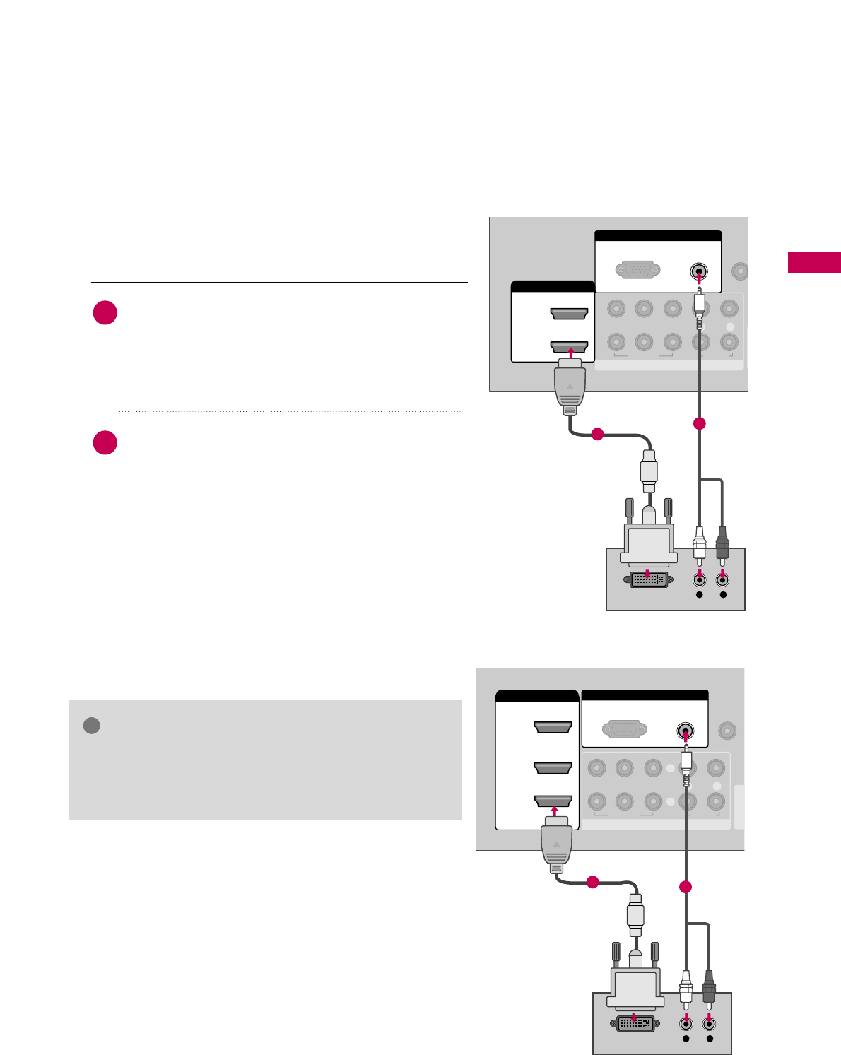
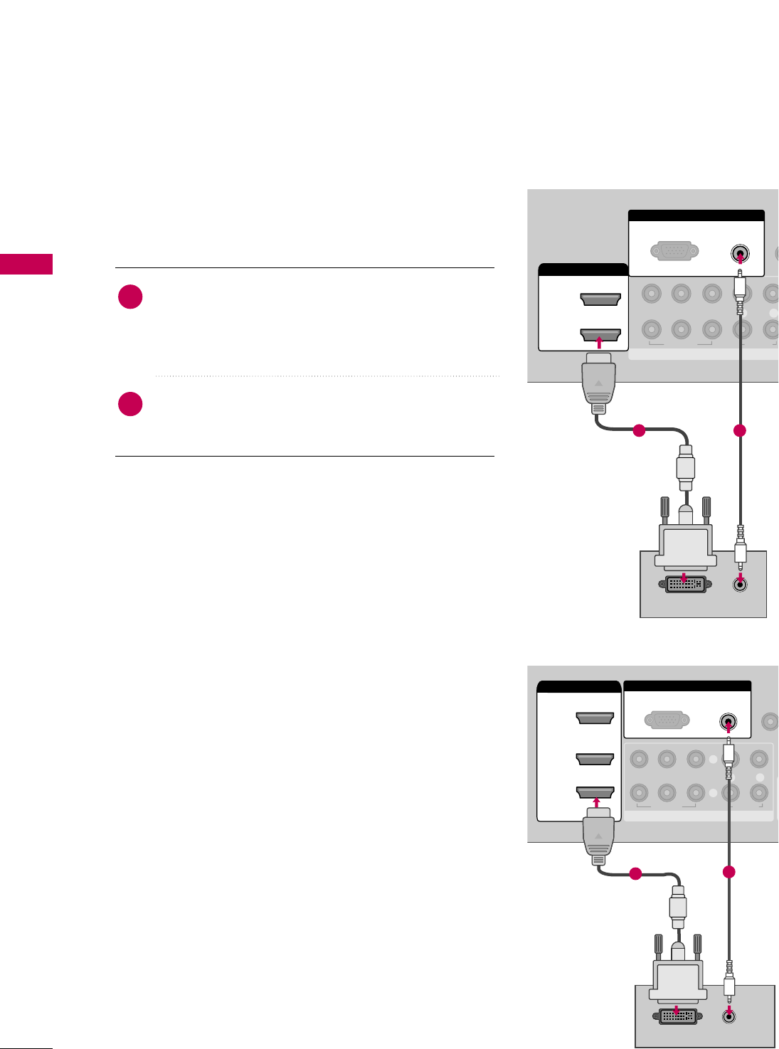
DVI to HDMI Connection
1. How to connect
2. How to use
■Turn on the digital set-top box. (Refer to the owner’s manu-
al for the digital set-top box.)
■LCD TV: Select the HHDDMMII11or HHDDMMII22input source on the TV
using the IINNPPUUTTbutton on the remote control.
Plasma TV: Select the HHDDMMII11,HHDDMMII22,orHHDDMMII33input
source on the TV using the IINNPPUUTTbutton on the remote
control.
2
1LCD TV: Connect the DVI output of the digital set-top
box to the HHDDMMII//DDVVII IINN 11or 22jack on the TV.
Plasma TV: Connect the DVI output of the digital set-
top box to the HHDDMMII//DDVVII IINN 11, 22, or 33jack on the
TV.
Connect the PC audio output to the AAUUDDIIOO
((RRGGBB//DDVVII))jack on the TV.
GGA DVI to HDMI cable or adapter is required for this con-
nection. DVI doesn't support audio, so a separate audio
connection is necessary.
NOTE
!
RGB IN
COMPONENT IN
AUDIO
(RGB/DVI)
RGB(PC)
REMO
CONTRO
1
2
VIDEO
LYP
BPRR
AUDIO
HDMI/DVI IN
2
1
L R
DVI-DTV OUTPUT
1
2
LCD TV
( )
RGB IN
COMPONENT IN
AUDIO
(RGB/DVI)
RGB(PC)
REMOTE
CONTROL IN
(CO
VIDEO
LYP
BPRR
AUDIO
AV IN 1
2
3
2
1
( )
HDMI/DVI IN
1
L R
DVI-DTV OUTPUT
1
Plasma TV
2
EXTERNAL EQUIPMENT SETUP
28
EXTERNAL EQUIPMENT SETUP
DVD SETUP
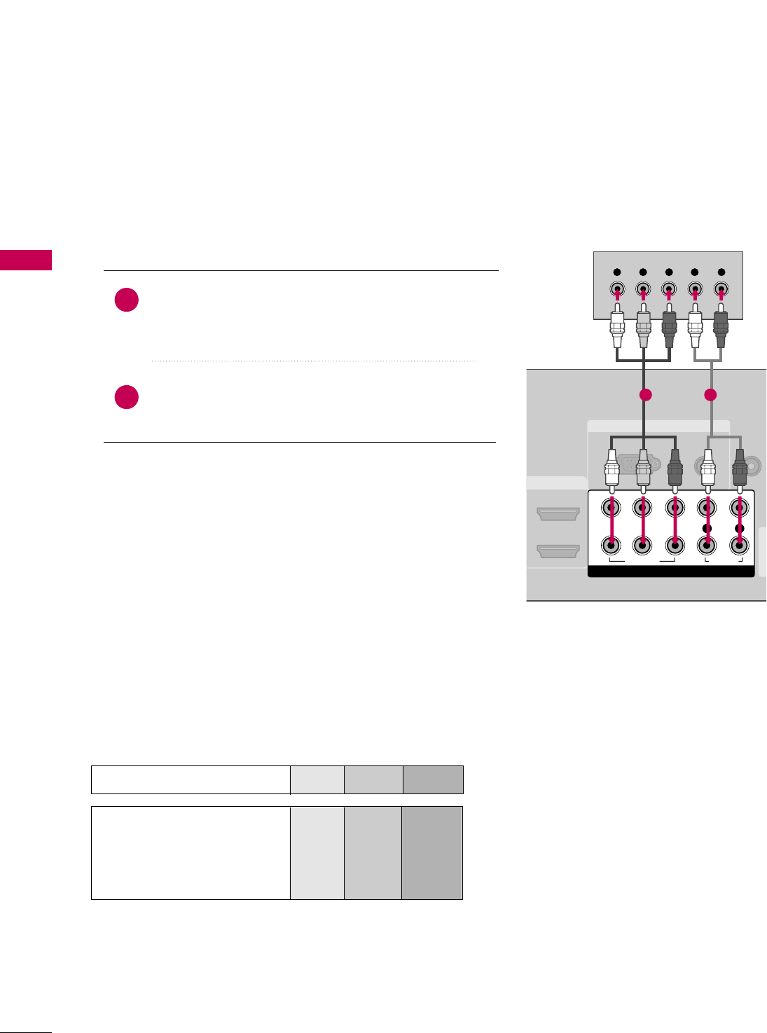
Component Connection
Component Input ports
To get better picture quality, connect a DVD player to the component input ports as shown below.
Component ports on the TV
YP
BPR
Video output ports
on DVD player
Y
Y
Y
Y
PB
B-Y
Cb
Pb
PR
R-Y
Cr
Pr
Connect the video outputs (Y, PB, PR)of the DVD to the
CCOOMMPPOONNEENNTT IINN VVIIDDEEOO11jacks on the TV.
Match the jack colors (Y = green, PB= blue, and PR= red).
Connect the audio outputs of the DVD to the
CCOOMMPPOONNEENNTT IINN AAUUDDIIOO11jacks on the TV.
1. How to connect
2. How to use
■Turn on the DVD player, insert a DVD.
■Select the CCoommppoonneenntt11input source on the TV using
the IINNPPUUTTbutton on the remote control.
■If connected to CCOOMMPPOONNEENNTT IINN 22input, select the
CCoommppoonneenntt 22input source on the TV.
■Refer to the DVD player's manual for operating instructions.
2
1
RGB IN
AUDIO
(RGB/DVI)
RGB(PC)
REMOTE
CONTROL
(C
AV IN 1
DMI/DVI IN
COMPONENT IN
1
2
VIDEO
LYP
BPRR
AUDIO
Y L RPBPR
1 2
EXTERNAL EQUIPMENT SETUP
29
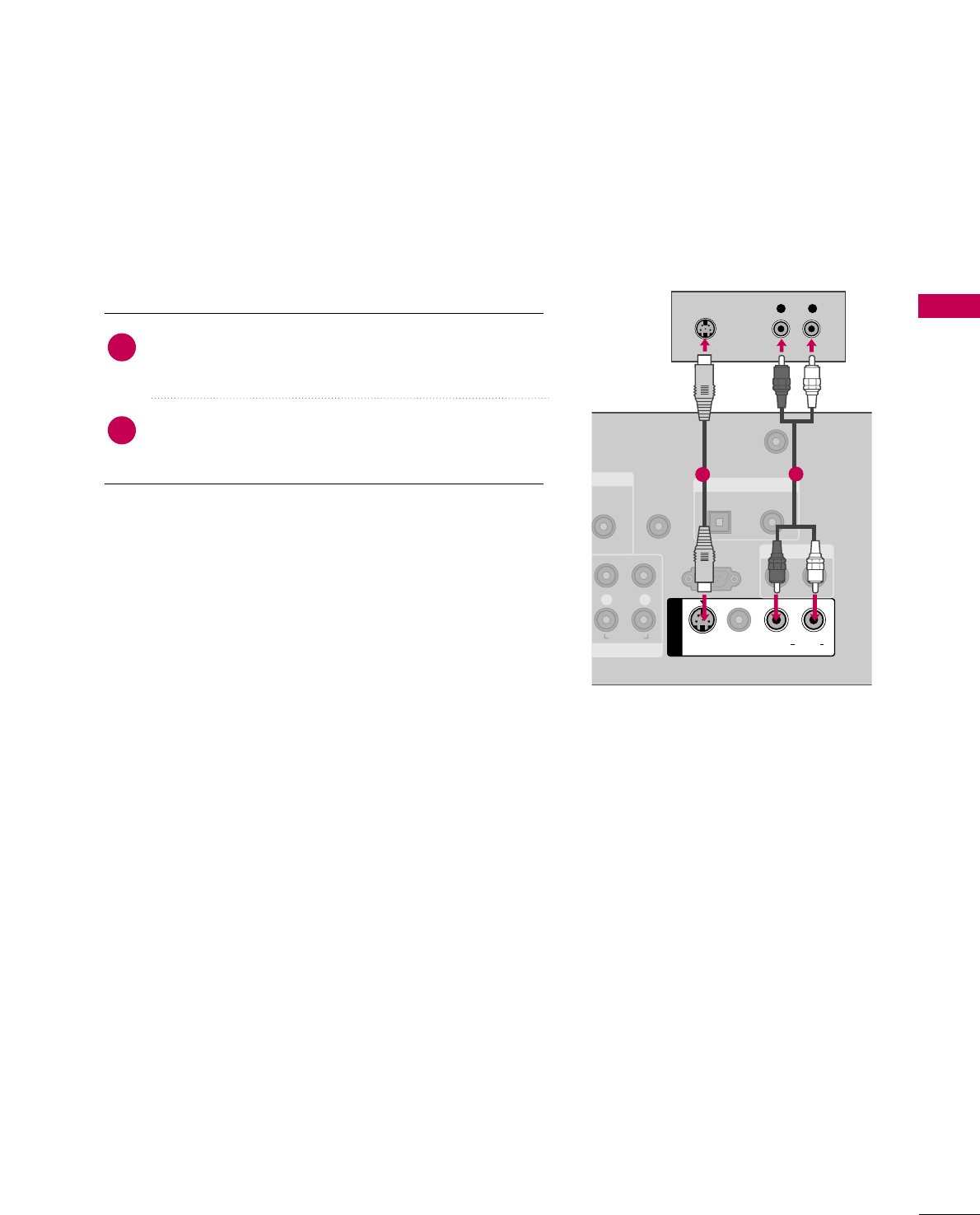
S-Video Connection
T IN
AUDIO
GB/DVI)
REMOTE
CONTROL IN
ANTENNA/
CABLE IN
RS-232C IN
(CONTROL & SERVICE)
L R
AUDIO
OPTICAL COAXIAL
DIGITAL AUDIO OUT
AUDIO OUT
AV IN 1
VIDEO LR
(MONO)
AUDIO
S-VIDEO
L R
S-VIDEO
AUDIO
12
Connect the S-VIDEO output of the DVD to the
SS--VVIIDDEEOOinput on the TV.
Connect the audio outputs of the DVD to the AAUUDDIIOO
input jacks on the TV.
1. How to connect
2. How to use
■Turn on the DVD player, insert a DVD.
■Select the AAVV11input source on the TV using the IINNPPUUTT
button on the remote control.
■Refer to the DVD player's manual for operating instructions.
2
1
EXTERNAL EQUIPMENT SETUP
30
EXTERNAL EQUIPMENT SETUP
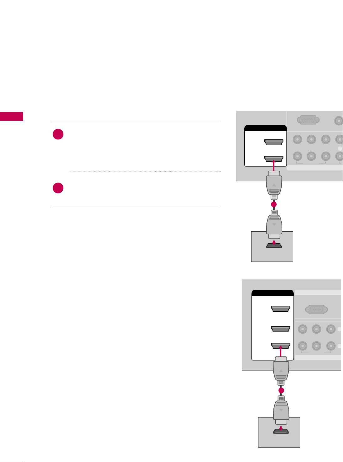
HDMI Connection
LCD TV: Connect the HDMI output of the DVD to the
HHDDMMII//DDVVII IINN11or 22jack on the TV.
Plasma TV: Connect the HDMI output of the DVD to
the HHDDMMII//DDVVII IINN11, 22, 33, or 44jack on the TV.
No separate audio connection is necessary.
HDMI supports both audio and video.
1. How to connect
2. How to use
■LCD TV: Select the HHDDMMII11or HHDDMMII22input source on the
TV using the IINNPPUUTTbutton on the remote control.
Plasma TV: Select the HHDDMMII11, HHDDMMII22, HHDDMMII33, or HHDDMMII44
input source on the TV using the IINNPPUUTTbutton on the
remote control.
■Refer to the DVD player's manual for operating instructions.
2
1
COMPONENT IN
AUDI
(RGB/D
RGB(PC)
1
2
VIDEO
LYP
BPR
A
HDMI/DVI IN
2
1
HDMI-DVD OUTPUT
1
LCD TV
RGB IN
COMPONENT
(R
RGB(PC)
VIDEO
YP
BPR
2
3
2
1
( )
HDMI/DVI IN
1
HDMI-DVD OUTPUT
1
Plasma TV
EXTERNAL EQUIPMENT SETUP
31
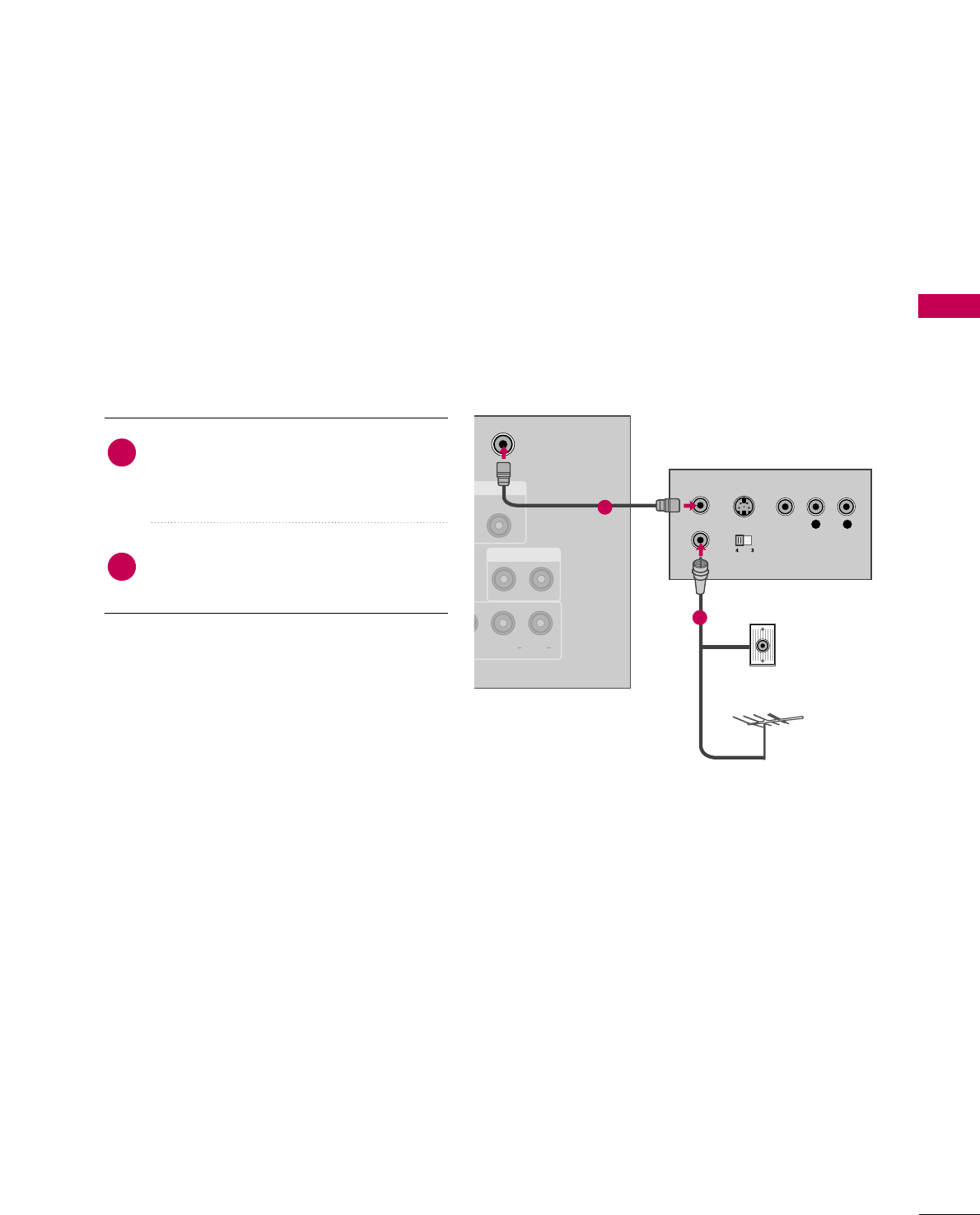
VCR SETUP
Antenna Connection
■To avoid picture noise (interference), leave an adequate distance between the VCR and TV.
■Use the ISM feature in the Option menu to avoid having a fixed image remain on the screen for a long period
of time
(
Plasma TV models
only)
. If the 4:3 picture format is used; the fixed images on the sides of the screen
may remain visible on the screen. This phenomenon is common to all TVs and is not covered by warranty.
ANTENNA/
CABLE IN
E)
COAXIAL
UDIO OUT
AUDIO OUT
EO L R
(MONO)
AUDIO
L R
S-VIDEO VIDEO
OUTPUT
SWITCH
ANT IN
ANT OUT
Wall Jack
Antenna
1
2
Connect the RF antenna out socket of the
VCR to the AANNTTEENNNNAA//CCAABBLLEE IINNsock-
et on the TV.
Connect the antenna cable to the RF
antenna in socket of the VCR.
1. How to connect
2. How to use
■Set VCR output switch to 3 or 4 and then
tune TV to the same channel number.
■Insert a video tape into the VCR and press
PLAY on the VCR. (Refer to the VCR owner’s
manual.)
2
1
EXTERNAL EQUIPMENT SETUP
32
EXTERNAL EQUIPMENT SETUP
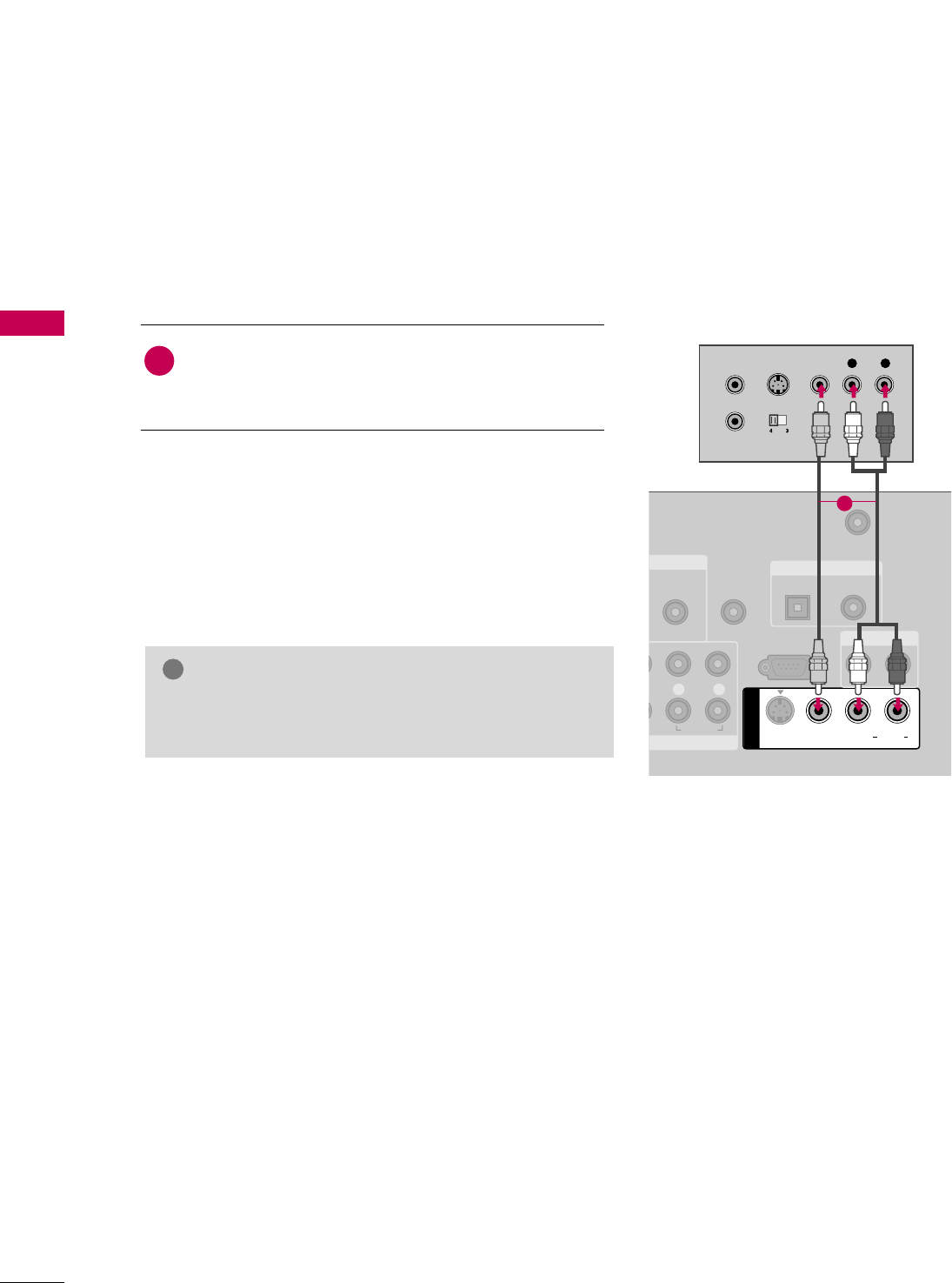
Composite (RCA) Connection
GGIf you have a mono VCR, connect the audio cable from
the VCR to the AAUUDDIIOO LL//MMOONNOOjack of the TV.
NOTE
!
NT IN
AUDIO
(RGB/DVI)
REMOTE
CONTROL IN
ANTENNA/
CABLE IN
RS-232C IN
(CONTROL & SERVICE)
L R
AUDIO
OPTICAL COAXIAL
DIGITAL AUDIO OUT
AUDIO OUT
AV IN 1
VIDEO L R
(MONO)
AUDIO
S-VIDEO
L R
S-VIDEO VIDEO
OUTPUT
SWITCH
ANT IN
ANT OUT
1
Connect the AAUUDDIIOO/VVIIDDEEOOjacks between TV and
VCR. Match the jack colors (Video = yellow, Audio Left
= white, and Audio Right = red)
1. How to connect
2. How to use
■Insert a video tape into the VCR and press PLAY on the VCR.
(Refer to the VCR owner’s manual.)
■Select the AAVV11input source on the TV using the IINNPPUUTT
button on the remote control.
■If connected to AAVV IINN22, select AAVV22input source on the TV.
1
EXTERNAL EQUIPMENT SETUP
33
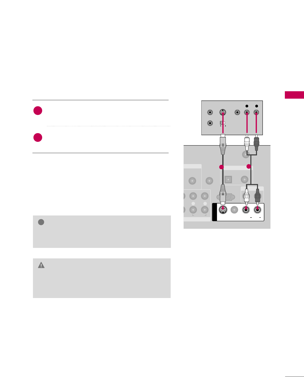
GGDo not connect to both Video and S-Video at the same
time. In the event that you connect both Video and the
S-Video cables, only the S-Video will work.
CAUTION
GGS-Video provides better quality than composite. Use it
when available.
NOTE
!
S-Video Connection
ENT IN
AUDIO
(RGB/DVI)
REMOTE
CONTROL IN
ANTENNA
CABLE IN
RS-232C IN
(CONTROL & SERVICE)
LRR
AUDIO
OPTICAL COAXIAL
DIGITAL AUDIO OUT
AUDIO OUT
AV IN 1
VIDEO LR
(MONO)
AUDIO
S-VIDEO
L R
S-VIDEO VIDEO
OUTPUT
SWITCH
ANT IN
ANT OUT
12
Connect the S-VIDEO output of the VCR to the
SS--VVIIDDEEOO input on the TV.
Connect the audio outputs of the VCR to the AAUUDDIIOO
input jacks on the TV.
1. How to connect
2. How to use
■Insert a video tape into the VCR and press PLAY on the VCR.
(Refer to the VCR owner’s manual.)
■Select the AAVV11input source on the TV using the IINNPPUUTT
button on the remote control.
2
1
EXTERNAL EQUIPMENT SETUP
34
EXTERNAL EQUIPMENT SETUP
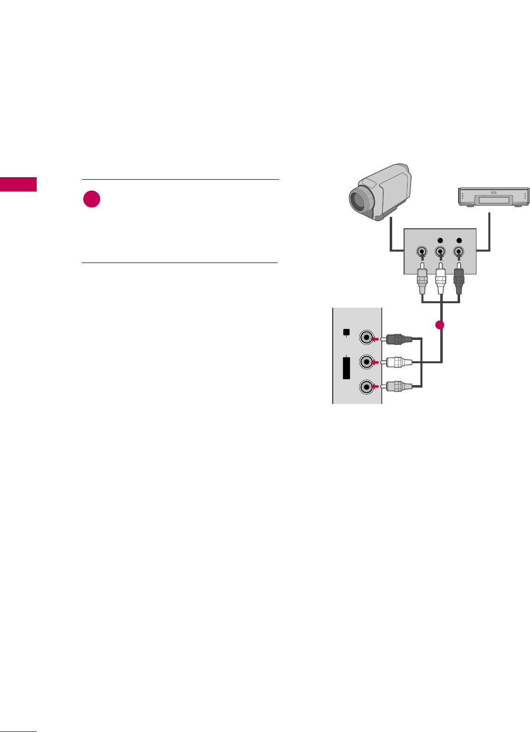
OTHER A/V SOURCE SETUP
L/MONO
R
AUDIO
VIDEO
USB IN
L R
VIDEO
Camcorder
Video Game Set
Connect the AAUUDDIIOO/VVIIDDEEOOjacks
between TV and external equipment.
Match the jack colors
.
(Video = yellow, Audio Left = white, and
Audio Right = red)
1. How to connect
2. How to use
■Select the AAVV22input source on the TV using
the IINNPPUUTTbutton on the remote control.
■If connected to AAVV IINN11input, select the AAVV11
input source on the TV.
■Operate the corresponding external equipment.
1
1
EXTERNAL EQUIPMENT SETUP
35
PC SETUP
This TV provides Plug and Play capability, meaning that the PC adjusts automatically to the TV's settings.
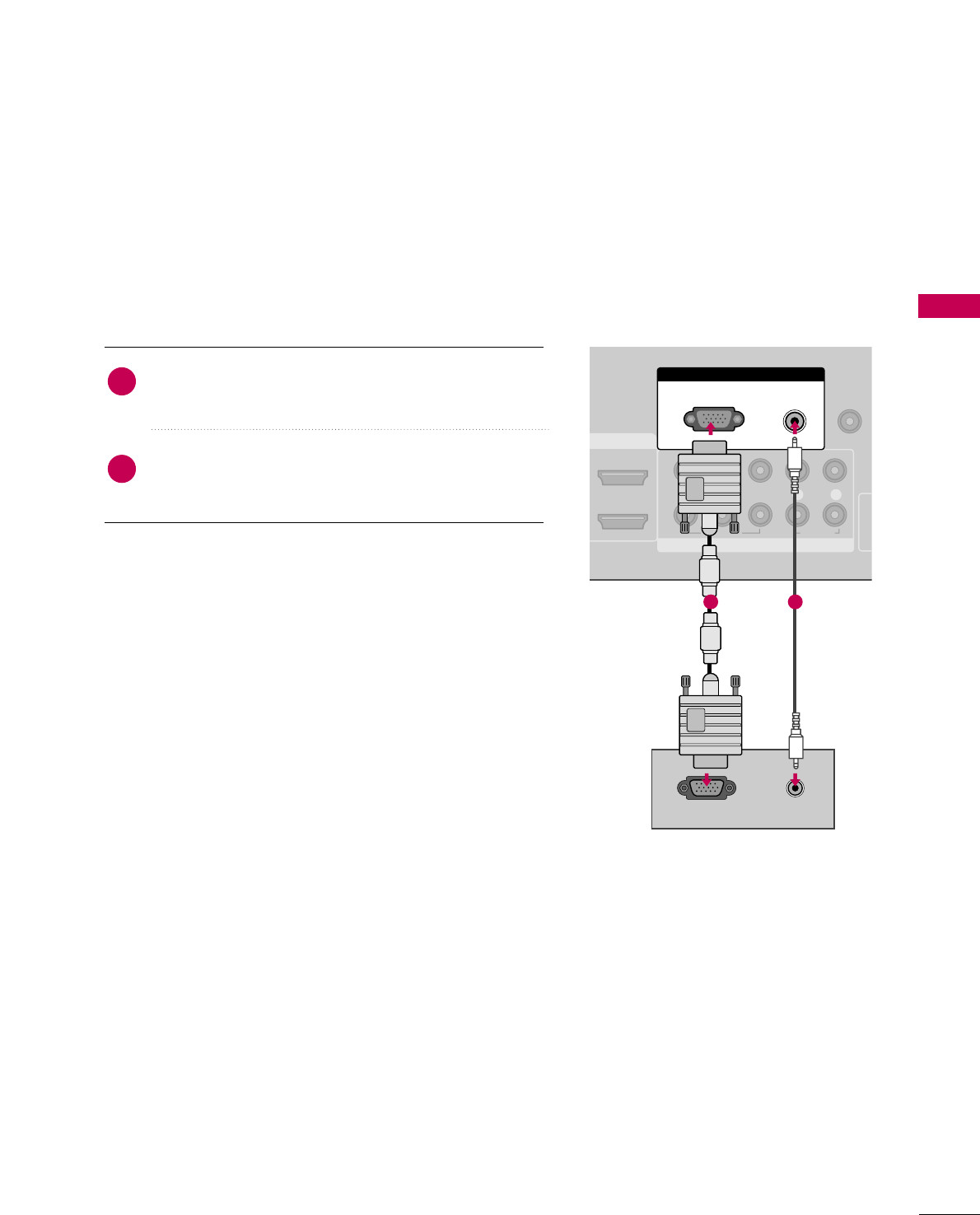
VGA (D-Sub 15 pin) Connection
Connect the VGA output of the PC to the RRGGBB
((PPCC)) jack on the TV.
Connect the PC audio output to the AAUUDDIIOO
((RRGGBB//DDVVII))jack on the TV.
1. How to connect
2. How to use
■Turn on the PC and the TV.
■Select the RRGGBB--PPCCinput source on the TV using the
IINNPPUUTTbutton on the remote control.
2
1
COMPONENT IN
REMOTE
CONTROL I
1
2
(CO
VIDEO
LYP
BPRR
AUDIO
MI/DVI IN
RGB IN
AUDIO
(RGB/DVI)
RGB(PC)
RGB OUTPUT AUDIO
1 2
EXTERNAL EQUIPMENT SETUP
36
EXTERNAL EQUIPMENT SETUP
LCD TV
Plasma TV
DVI to HDMI Connection
LCD TV: Connect the DVI output of the PC to the
HHDDMMII//DDVVII IINN 11or 22 jack on the TV.
Plasma TV: Connect the DVI output of the PC to the
HHDDMMII//DDVVII IINN 11, 22, or 33 jack on the TV.
Connect the PC audio output to the AAUUDDIIOO
((RRGGBB//DDVVII)) jack on the TV.
1. How to connect
2. How to use
■Turn on the PC and the TV.
■LCD TV: Select the HHDDMMII11or HHDDMMII22 input source on the TV
using the IINNPPUUTTbutton on the remote control.
Plasma TV: Select the HHDDMMII11,HHDDMMII22,orHHDDMMII33input source
on the TV using the IINNPPUUTTbutton on the remote control.
2
1
COMPONENT IN
RE
CON
1
2
VIDEO
LYP
BPRR
AUDIO
HDMI/DVI IN
2
1
RGB IN
AUDIO
(RGB/DVI)
RGB(PC)
DVI-PC OUTPUT AUDIO
1 2
RGB IN
COMPONENT IN
AUDIO
(RGB/DVI)
RGB(PC)
REMOT
CONTRO
VIDEO
LYP
BPRR
AUDIO
2
3
2
1
( )
HDMI/DVI IN
1
DVI-PC OUTPUT AUDIO
12
EXTERNAL EQUIPMENT SETUP
37
GG32/37/42LG30DC, 42PG60C: To get the the
best picture quality, adjust the PC graphics card to
1360x768.
GG47/52LG50DC: To get the the best picture quali-
ty, adjust the PC graphics card to 1920x1080.
GGDepending on the graphics card, DOS mode may
not work if a HDMI to DVI Cable is in use.
GGIn PC mode, there may be noise associated with
the resolution, vertical pattern, contrast or bright-
ness. If noise is present, change the PC output to
another resolution, change the refresh rate to
another rate or adjust the brightness and contrast
on the PICTURE menu until the picture is clear.
GGAvoid keeping a fixed image on the screen for a
long period of time. The fixed image could become
permanently imprinted on the screen.
GGThe synchronization input form for Horizontal and
Vertical frequencies is separate.
GGDepending on the graphics card, some resolution
settings may not allow the image to be positioned
on the screen properly.
GGIf there are overscan in HDMI-PC 1920x1080,
change aspect ratio to JJuusstt ssccaann.
NOTES
!
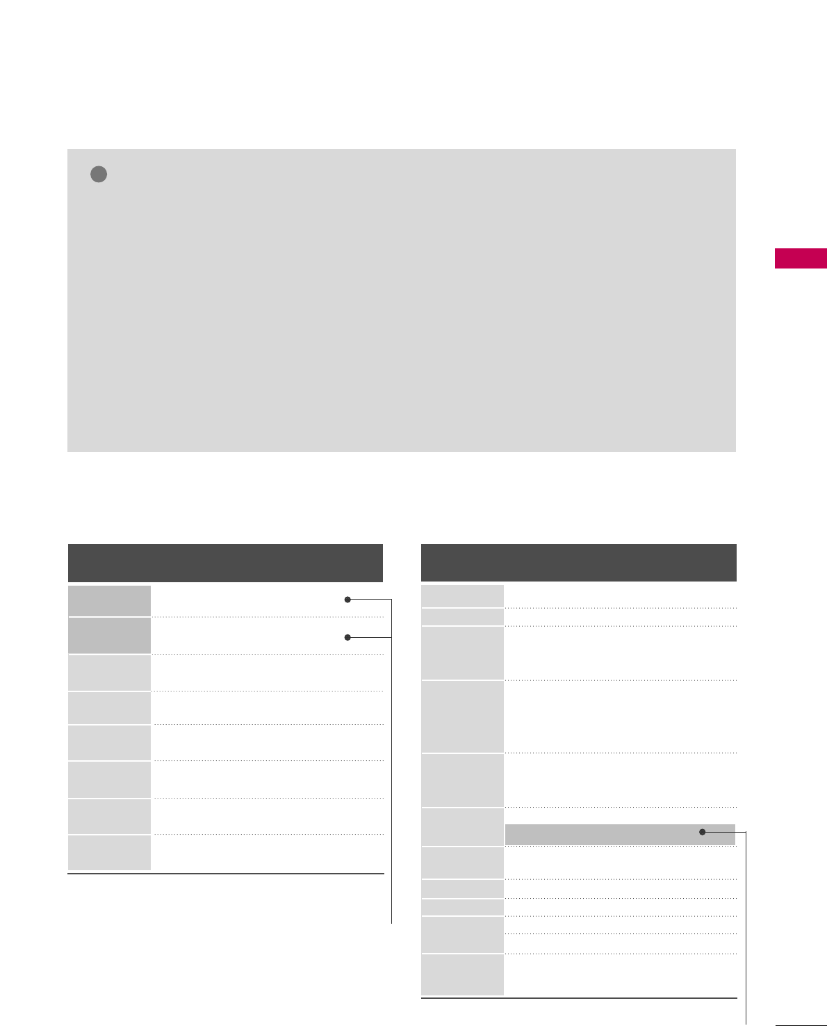
Supported Display Specifications (RGB-PC, HDMI-PC)
Horizontal Vertical
Frequency(KHz)Frequency(Hz)
31.469 70.08
31.469 70.08
31.469 59.94
37.879 60.31
48.363 60.00
47.776 59.87
47.720 59.799
47.130 59.65
Resolution
720x400
1360x768
640x350
640x480
800x600
1024x768
1280x768
1366x768
For 32/37/42LG30DC
For 47/52LG50DC, Plasma TV
* Only RGB-PC mode
Resolution
640x350
Horizontal Vertical
Frequency(KHz)Frequency(Hz)
31.468 70.09
31.469 70.08
31.469 59.94
37.500 75.00
37.861 72.80
35.156 56.25
37.879 60.31
46.875 75.00
48.077 72.18
48.363 60.00
56.476 70.06
60.023 75.02
47.776 59.87
60.289 74.893
63.981 60.02
79.976 75.025
47.712 60.015
75.00 60.00
66.587 59.934
67.5 60.00
66.587 59.934
* Only RGB-PC mode
720x400
1360x768
640x480
800x600
1024x768
1280x1024
1600x1200
LCD TV
1920x1080
Plasma TV
1920x1080
RGB-PC
HDMI-PC
1280x768
EXTERNAL EQUIPMENT SETUP
38
EXTERNAL EQUIPMENT SETUP
Screen Setup for PC mode
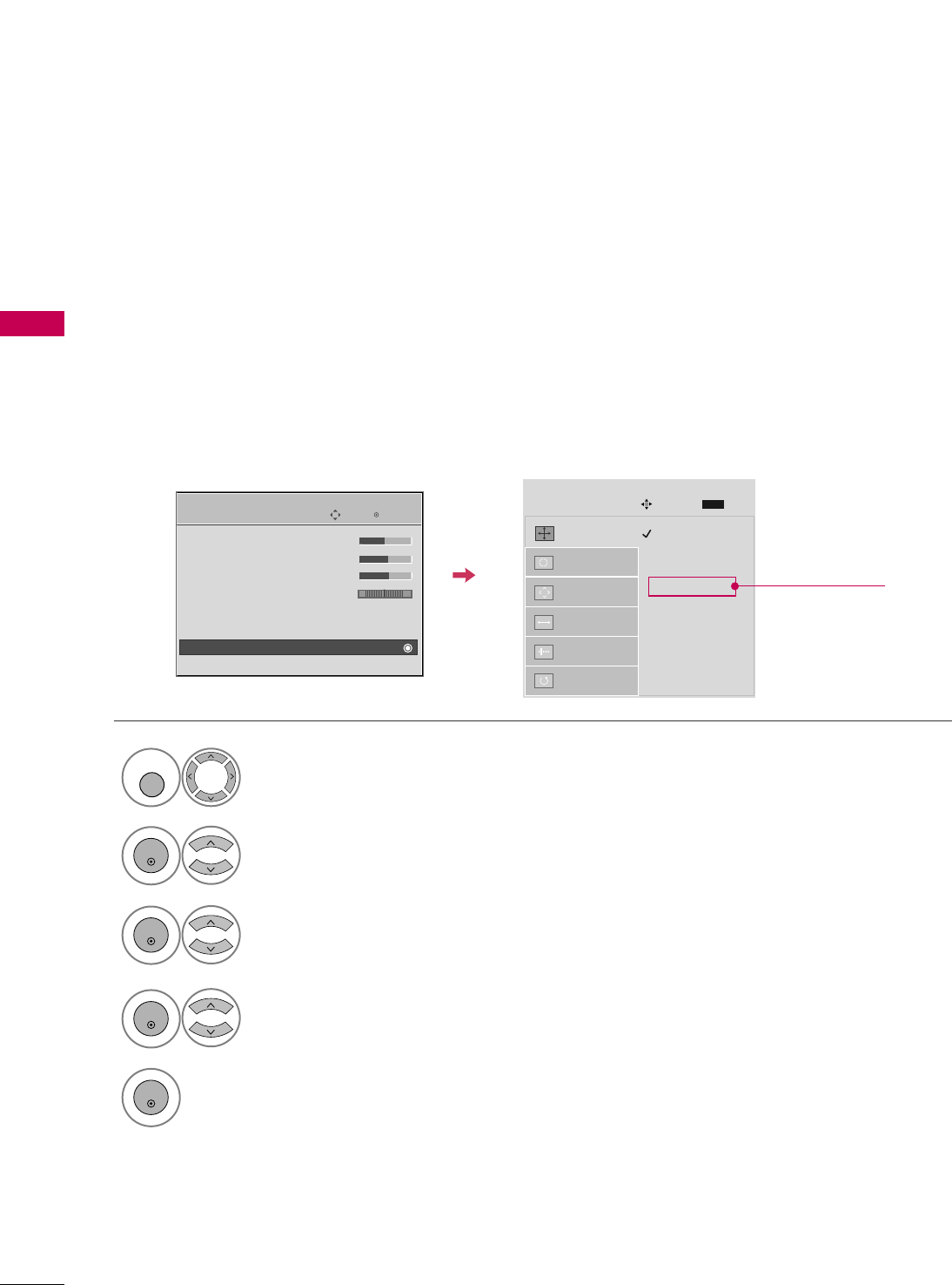
Selecting Resolution
You can choose the resolution in RGB-PC mode.
The PPoossiittiioonn, PPhhaassee, and SSiizzeecan also be adjusted.
Select PPIICCTTUURREE.
Select SSccrreeeenn ((RRGGBB--PPCC)).
Select RReessoolluuttiioonn.
Select the desired resolution.
1024 x 768
1280 x 768
1360 x 768
1366 x 768
Auto config.
Resolution
G
Position
Size
Phase
Reset
SCREEN
Move
Prev.
MENU
1
MENU
3
4
2
ENTER
ENTER
ENTER
5
ENTER
Enter
Move
PICTURE
E
• Brightness 50
• Sharpness 60
• Color 60
• Tint 0
• Advanced Control
• Reset
Screen (RGB-PC)
TruMotion Demo
RG Only for
32/37/42LG30DC
EXTERNAL EQUIPMENT SETUP
39
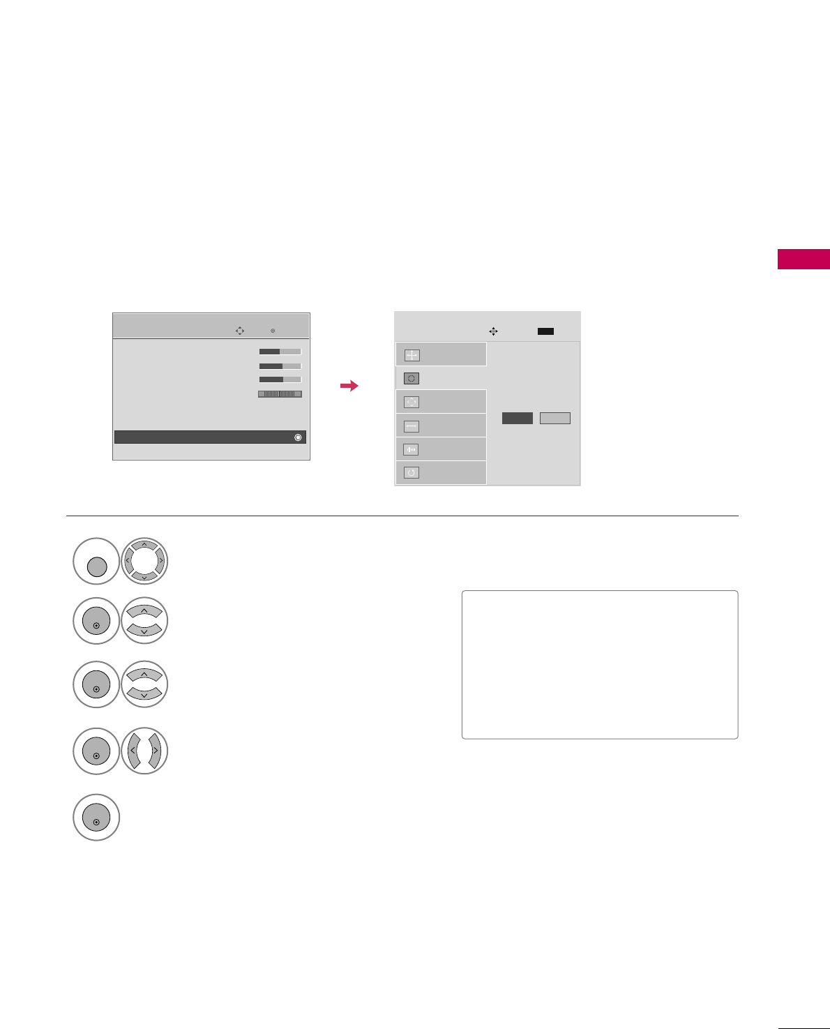
Auto Configure
Automatically adjusts picture position and minimizes image instability. After adjustment, if the image is still
not correct, try using the manual settings or a different resolution or refresh rate on the PC.
Select SSccrreeeenn ((RRGGBB--PPCC)).
Select AAuuttoo ccoonnffiigg...
Auto config. G
Resolution
Position
Size
Phase
Reset
SCREEN
Move
Prev.
MENU
To Set
3
2
ENTER
ENTER
Select YYeess.
4
ENTER
Start Auto Configuration.
5
ENTER
Select PPIICCTTUURREE.
1
MENU
• If the position of the image is still not
correct, try Auto adjustment again.
• If picture needs to be adjusted again
after Auto adjustment in RGB-PC, you
can adjust the PPoossiittiioonn, SSiizzee or
PPhhaassee.
Enter
Move
PICTURE
E
• Brightness 50
• Sharpness 60
• Color 60
• Tint 0
• Advanced Control
• Reset
Screen (RGB-PC)
TruMotion Demo
RG
Yes No
EXTERNAL EQUIPMENT SETUP
40
EXTERNAL EQUIPMENT SETUP
Adjustment for screen Position, Size, and Phase
If the picture is not clear after auto adjustment and especially if characters are still trembling, adjust the picture
phase manually.
This feature operates only in RGB-PC mode.
Select PPoossiittiioonn, SSiizzee, or PPhhaassee.
Make appropriate adjustments.
Auto config.
Resolution
Position
G
Size
Phase
Reset
GF
D
E
SCREEN
Move
Prev.
MENU
3
ENTER
4
ENTER
■PPoossiittiioonn: This function is to adjust pic-
ture to left/right and up/down as you
prefer.
■SSiizzee: This function is to minimize any
vertical bars or stripes visible on the
screen background. And the horizontal
screen size will also change.
■PPhhaassee: This function allows you to
remove any horizontal noise and clear or
sharpen the image of characters.
Select PPIICCTTUURREE.
Select SSccrreeeenn ((RRGGBB--PPCC)).
1
MENU
2
ENTER
5
ENTER
Enter
Move
PICTURE
E
• Brightness 50
• Sharpness 60
• Color 60
• Tint 0
• Advanced Control
• Reset
Screen (RGB-PC)
TruMotion Demo
RG
EXTERNAL EQUIPMENT SETUP
41
Screen Reset (Reset to original factory values)
Returns PPoossiittiioonn, SSiizzee, and PPhhaasseeto the default factory settings.
This feature operates only in RGB-PC mode.
Auto config.
Position
Resolution
Size
Phase
Reset
G
SCREEN
Move
Prev.
MENU
To Set
Select RReesseett.
3
ENTER
Select PPIICCTTUURREE.
Select SSccrreeeenn ((RRGGBB--PPCC)).
1
MENU
2
ENTER
Select YYeess.
4
ENTER
5
ENTER
Enter
Move
PICTURE
E
• Brightness 50
• Sharpness 60
• Color 60
• Tint 0
• Advanced Control
• Reset
Screen (RGB-PC)
TruMotion Demo
RG
Yes No
EXTERNAL EQUIPMENT SETUP
42
EXTERNAL EQUIPMENT SETUP
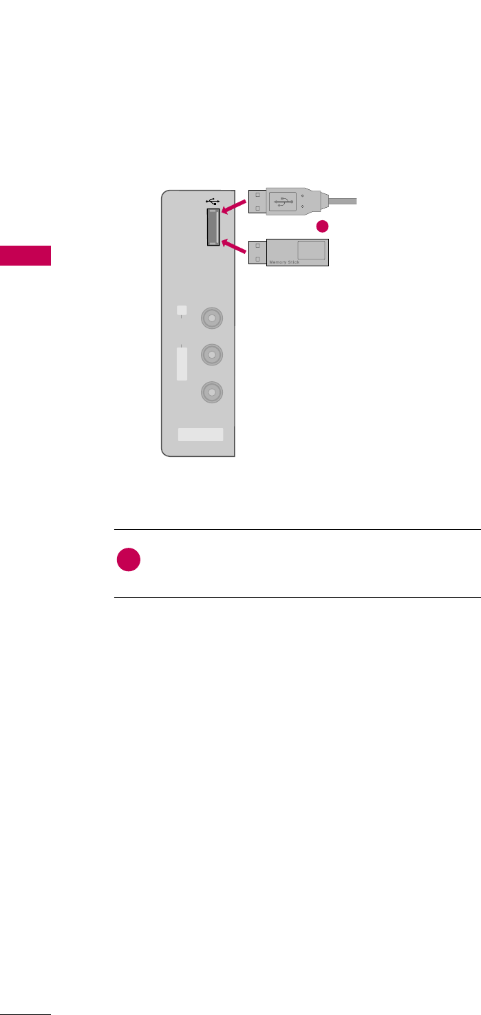
USB CONNECTION
(Except 32/37/42LG30DC)
AV IN 2
L/MONO
R
AUDIO
VIDEO
USB IN
Connect the USB device to the UUSSBB IINNjack on the side
of TV.
1. How to connect
1
2. How to use
■After connecting the UUSSBB IINNjack, you use the USB func-
tion. (GGpp..6600)
1
or
i.e)
EXTERNAL EQUIPMENT SETUP
43
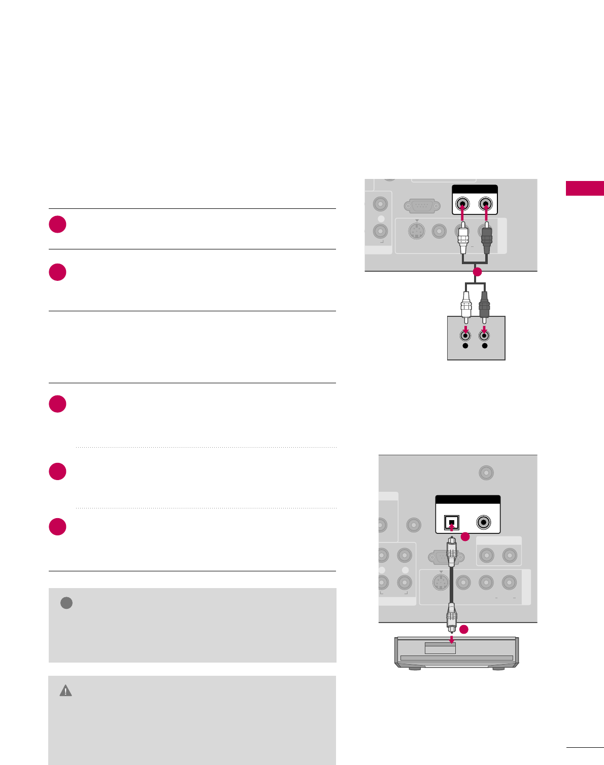
AUDIO OUT CONNECTION
Send the TV’s audio to external audio equipment via the Audio Output port.
RS-232C IN
(CONTROL & SERVICE)
R
AUDIO
AUDIO OUT
AV IN 1
VIDEO L R
(MONO)
AUDIO
S-VIDEO
L R
AUDIO
1
N
UDIO
B/DVI)
REMOTE
CONTROL IN
ANTENNA/
CABLE IN
RS-232C IN
(CONTROL & SERVICE)
L R
AUDIO
OPTICAL COAXIAL
DIGITAL AUDIO OUT
AUDIO OUT
AV IN 1
VIDEO L R
(MONO)
AUDIO
S-VIDEO
1
2
GGWhen connecting with external audio equipments, such as
amplifiers or speakers, you can turn the TV speakers off in
the menu. (GG pp..8877)
NOTE
!
GDo not look into the optical output port. Looking at the
laser beam may damage your vision.
GGBlock the SPDIF out (optical/coaxial) about the contents
with ACP(Audio Copy Protection) function.
CAUTION
Connect one end of the optical or coaxial cable to the
TV’s OOPPTTIICCAALL or CCOOAAXXIIAALL(Except 32/37/42LG30DC)
port of DDIIGGIITTAALL AAUUDDIIOO OOUUTT.
Connect the other end of the optical or coaxial cable to
the digital audio input on the audio equipment.
Set the “TV Speaker option - Off” in the AUDIO menu. (GG
pp..8877). See the external audio equipment instruction manu-
al for operation.
1. How to connect
2
3
1
Connect audio outputs to the TV’s AAUUDDIIOO OOUUTTjacks.
Set the “TV Speaker option - Off” in the AUDIO menu.
(GGpp..8877). See the external audio equipment instruction
manual for operation.
1. How to connect
2
1
Analog
Digital
WATCHING TV / CHANNEL CONTROL
44
REMOTE CONTROL FUNCTIONS
WATCHING TV / CHANNEL CONTROL
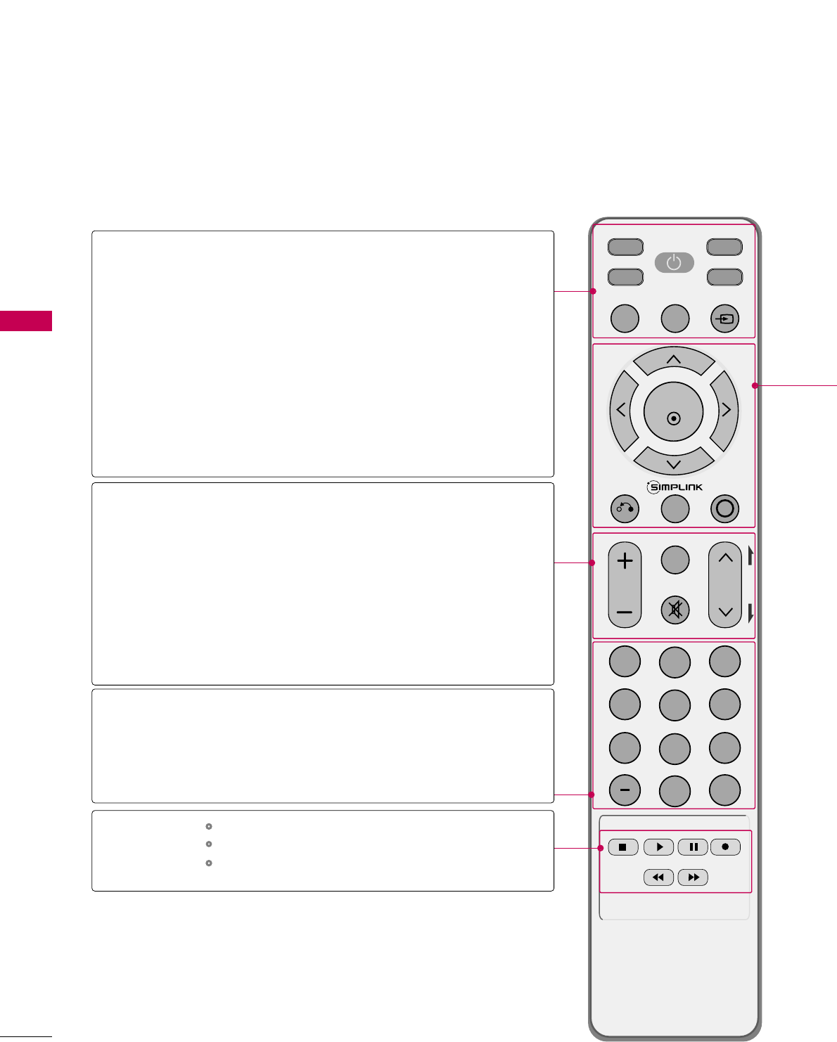
When using the remote control, aim it at the remote control sensor on the TV.
INPUT
FAV
MUTE
TV
STB
POWER
Q. MENU MENU
AV MODERETURN
ENTER
VOL CH
123
456
78
0
9
FLASHBK
P
A
G
E
DVD
VCR
TV/STB/DVD/VCR
POWER
Q.MENU
MENU
INPUT
VOLUME UP
/DOWN
FAV
MUTE
CHANNEL
UP/DOWN
PAGE
UP/DOWN
— (DASH)
FLASHBK
Select the remote operating mode: TV, STB, DVD, or VCR.
Turns your TV or any other programmed equipment on or
off, depending on the mode.
Select the desired quick menu source. GGpp..4477
Displays the main menu.
Clear all on-screen displays and return to TV viewing from
any menu.
External input modes rotate in regular sequence.
Increase/decrease the sound level.
Scroll through the programmed Favorite channels. GGpp..4477
Switch the sound on or off. GGpp..4466
Select available channels.
Move from one full set of screen information to the next one.
Used to enter a program number for multiple
program channels such as 2-1, 2-2, etc.
Tune to the last channel viewed.
Control video cassette recorders or DVD players.
Control USB menu (PHOTO LIST and MUSIC LIST.)
Control the SIMPLINK compatible devices.
NUMBER button
VCR/DVD, USB,
SIMPLINK
Control buttons
WATCHING TV / CHANNEL CONTROL
45
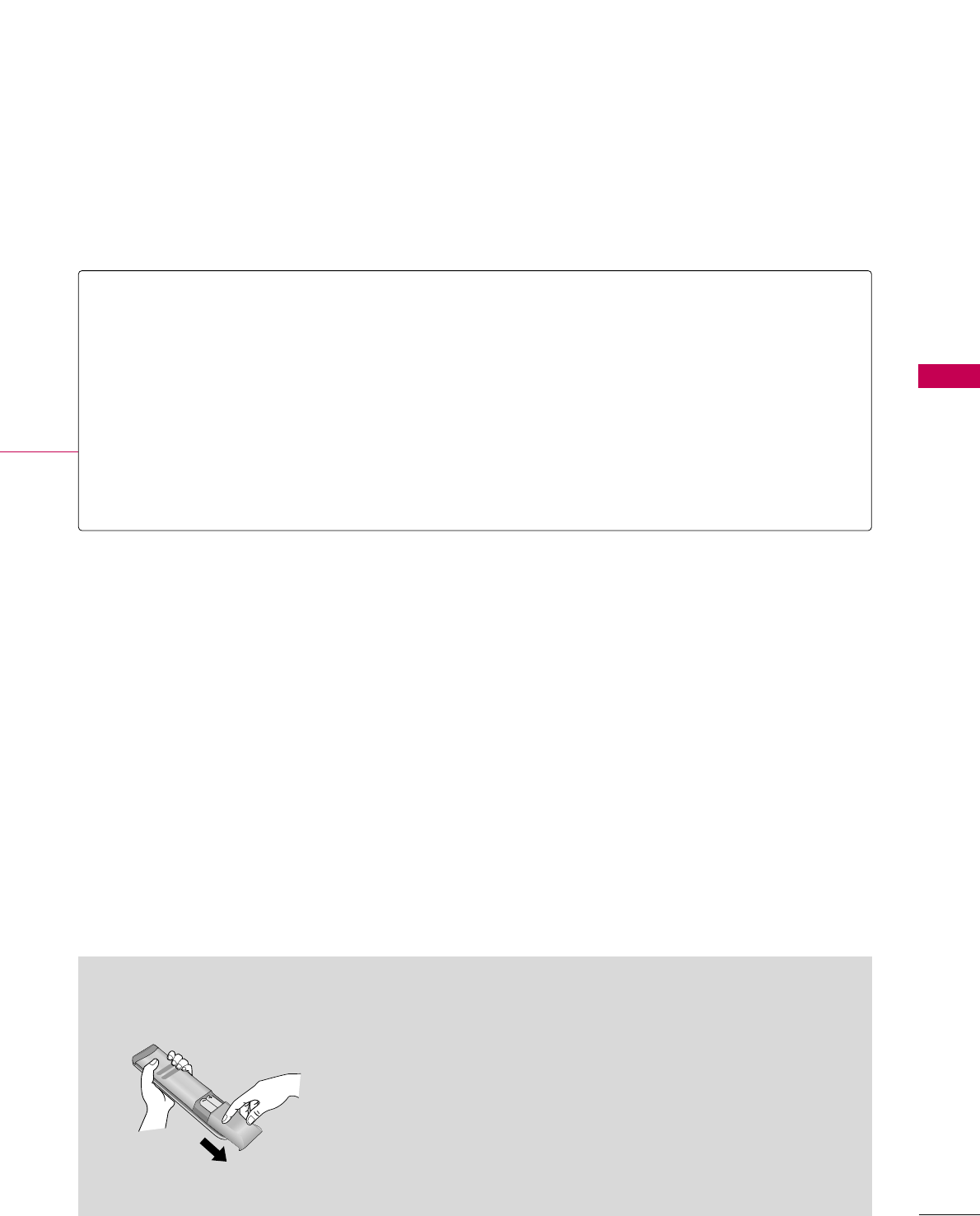
Installing Batteries
■
Open the battery compartment cover on the back side and install
the batteries matching correct polarity (+with +,-with -).
■
Install two 1.5V AAA batteries. Don’t mix old or used batteries with
new ones.
■
Close cover.
THUMBSTICK
(Up/Down/Left
Right/ENTER)
RETURN
SIMPLINK
AV MODE
Navigate the on-screen menus and adjust the system settings to your preference.
Allows the user to move return one step in an interactive application or other user interaction
function.
See a list of AV devices connected to TV.
When you toggle this button, the SIMPLINK menu appears at the screen. GGpp..5588--5599
It helps you select and set images and sounds. GGpp..5577
WATCHING TV / CHANNEL CONTROL
46
WATCHING TV / CHANNEL CONTROL
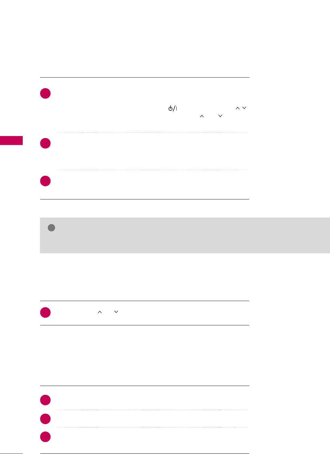
TURNING ON THE TV
NOTE
!
GGIf you intend to be away on vacation, disconnect the power plug from the wall power outlet.
First, connect power cord correctly.
At this moment, the TV switches to standby mode.
■In standby mode to turn TV on, press the , IINNPPUUTT,CCHH ((DDEEor ))
button on the TV or press the PPOOWWEERR, IINNPPUUTT, CCHH((or )), NNuummbbeerr
((00~99))button on the remote control.
Select the viewing source by using the IINNPPUUTTbutton on the remote control.
■This TV is programmed to remember which power state it was last set to,
even if the power cord is out.
When finished using the TV, press the PPOOWWEERRbutton on the remote control.
The TV reverts to standby mode.
1
2
3
Press the CCHH((or ))or NNUUMMBBEERRbuttons to select a channel number.
1
VOLUME ADJUSTMENT
CHANNEL SELECTION
Press the VVOOLL((++ or --))button to adjust the volume.
If you want to switch the sound off, press the MMUUTTEEbutton.
You can cancel the Mute function by pressing the MMUUTTEEor VVOOLL((++ or --))
button.
Adjust the volume to suit your personal preference.
1
2
3
WATCHING TV / CHANNEL CONTROL
47
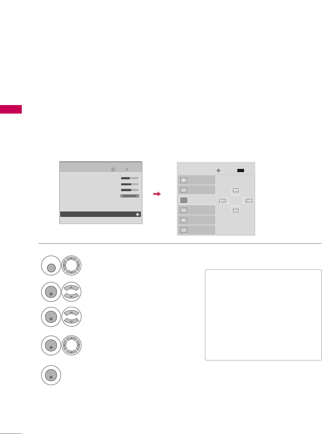
QUICK MENU
Display each menu.
Make appropriate adjustments.
■AAssppeecctt RRaattiioo: Selects your desired picture format.
■PPoowweerr SSaavviinngg (Plasma TV Only): Adjusts screen
brightness to reduce the power consumption of the
TV.
■BBaacckklliigghhtt (LCD TV Only): Adjust the brightness
of LCD panel to control the brightness of the screen.
■CClleeaarr VVooiiccee: By differentiating the human sound
range from others, it helps make human voices
sound better.
■PPiiccttuurree MMooddee: Selects the factory preset picture
depend on the viewing environment.
■SSoouunndd MMooddee: Selects the factory preset sound for
type of program.
■CCaappttiioonn: Select on or off.
■MMuullttii AAuuddiioo: Changes the audio language (Digital
signal).
SSAAPP: Selects MTS sound (Analog signal).
■SSlleeeepp TTiimmeerr: Select the amount of time before
your TV turns off automatically.
■DDeell//AAdddd//FFaavv: Select channel you want to add/delete
or add the channel to the Favorite List.
■UUSSBB EEjjeecctt: Select “USB Eject” in order to eject
USB device.
Your TV's OSD (On Screen Display) may differ slightly from what is shown in this manual.
Q.Menu (Quick Menu) is a menu of features which users might use frequently.
1
Q. MENU
2
LCD TV
Q.Menu
3
FF16:9 GG
Vivid
Off
Standard
Off
English
Off
Add
Eject
Aspect Ratio
Backlight
Clear Voice
Picture Mode
Sound Mode
Caption
Multi Audio
Sleep Timer
Del/Add/Fav
USB Eject
CH
Plasma TV
Q.Menu
Close Close
3
FF16:9 GG
Vivid
Off
Standard
Off
English
Off
Add
Eject
Aspect Ratio
Power Saving
Clear Voice
Picture Mode
Sound Mode
Caption
Multi Audio
Sleep Timer
Del/Add/Fav
USB Eject
CH
3
Q. MENU
Return to TV viewing.
Except 32/37/42LG30DC
WATCHING TV / CHANNEL CONTROL
48
WATCHING TV / CHANNEL CONTROL
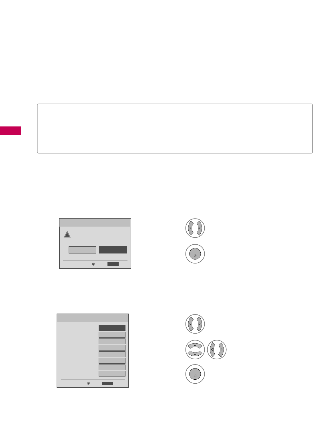
INITIAL SETTING
This Function guides the user to easily set the essential items for viewing the TV for the first time when pur-
chasing the TV. If will be displayed on the screen when turning the TV on for the first time. It can also be acti-
vated from the user menus.
Select HHoommeeMode.
1
2
ENTER
Select AAuuttooor MMaannuuaall.
Select desired time option.
1
3
ENTER
2
Year
Current Time Setting
2007
Month 11
Date 15
Hour 5 PM
Minute 52
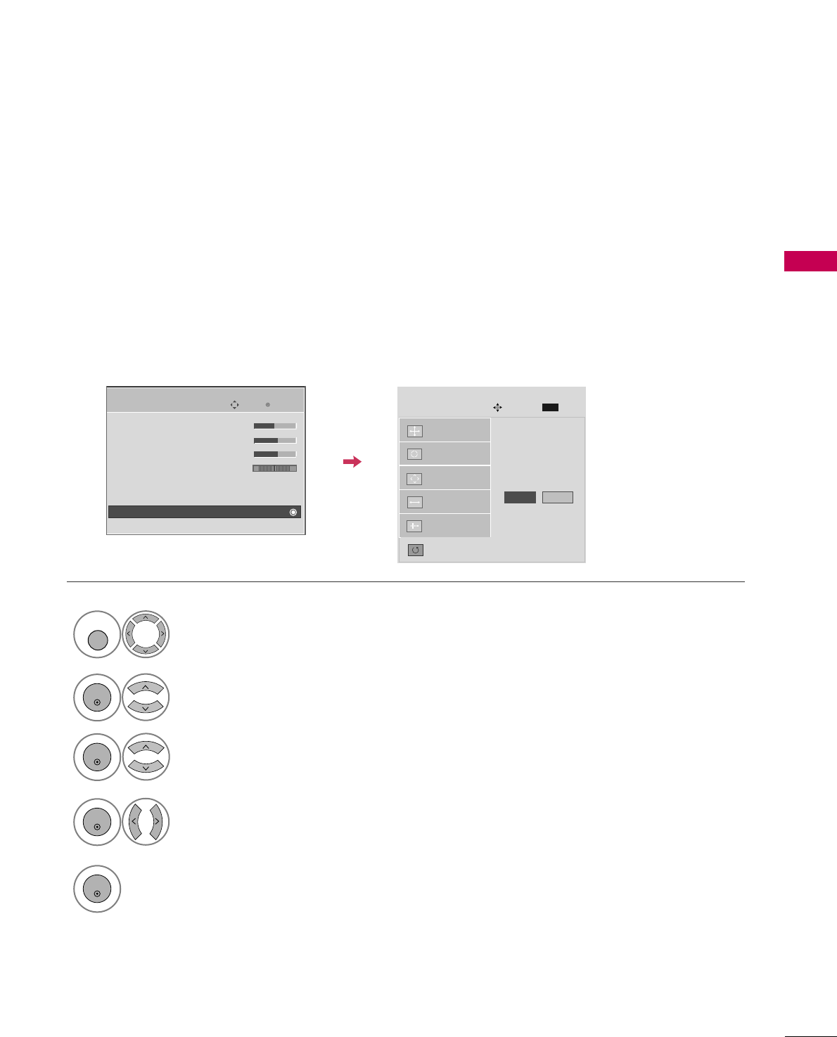
Time Zone Eastern
Daylight Saving
Off
FF Auto GG
ExitEnter
RETURN
Step2. Time Setting
Selecting the environment.
Choose the setting mode you want.
In Store
Home
ExitEnter
RETURN
Step1. Mode Setting
Step1. Mode setting
Step2. Time setting
■Default selection is “HHoommee”. We recommend setting the TV to “HHoommee” mode for the best picture in your
home environment.
■“IInn--ssttoorree” Mode is only intended for use in retail environments. Customers can adjust the “PPiiccttuurreemenu -
PPiiccttuurree mmooddee” manually while inspecting the TV, but the TV will automatically return to preset in-store
mode after 5 minutes.
!
WATCHING TV / CHANNEL CONTROL
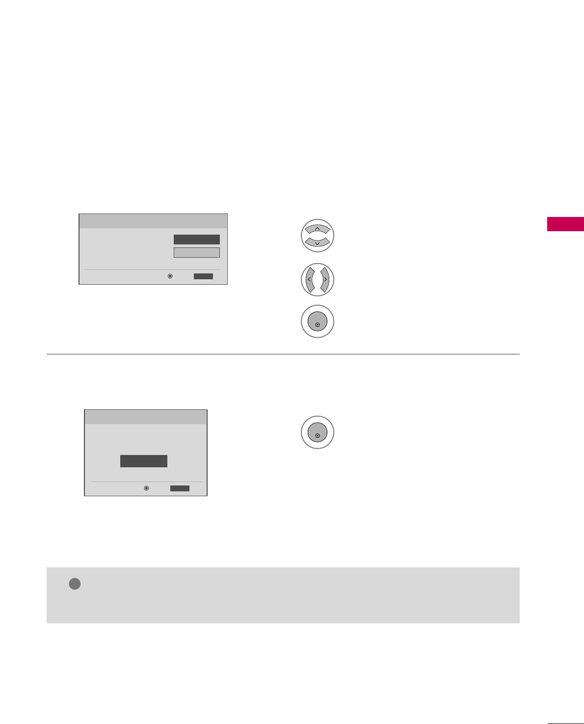
49
Select OOSSDD LLaanngguuaaggee SSeettttiinnggor
AAuuddiioo LLaanngguuaaggee SSeettttiinngg.
Start AAuuttoo TTuunniinngg.
Select your desired language.
1
3
ENTER
1
ENTER
2
Auto Tuning can change channel map.
Do you want to start Auto Tuning?
Enter
Exit
Enter
RETURN
Step4. Auto Tuning
ExitEnter
RETURN
Step3. Option Setting
1. OSD Language Setting
FFEnglish GG
2. Audio Language Setting French
Step3. Option setting
Step4. Auto Tuning
■ You can also adjust IInniittiiaall SSeettttiinnggin the OOPPTTIIOONN menu.
NOTE
!
WATCHING TV / CHANNEL CONTROL
50
WATCHING TV / CHANNEL CONTROL
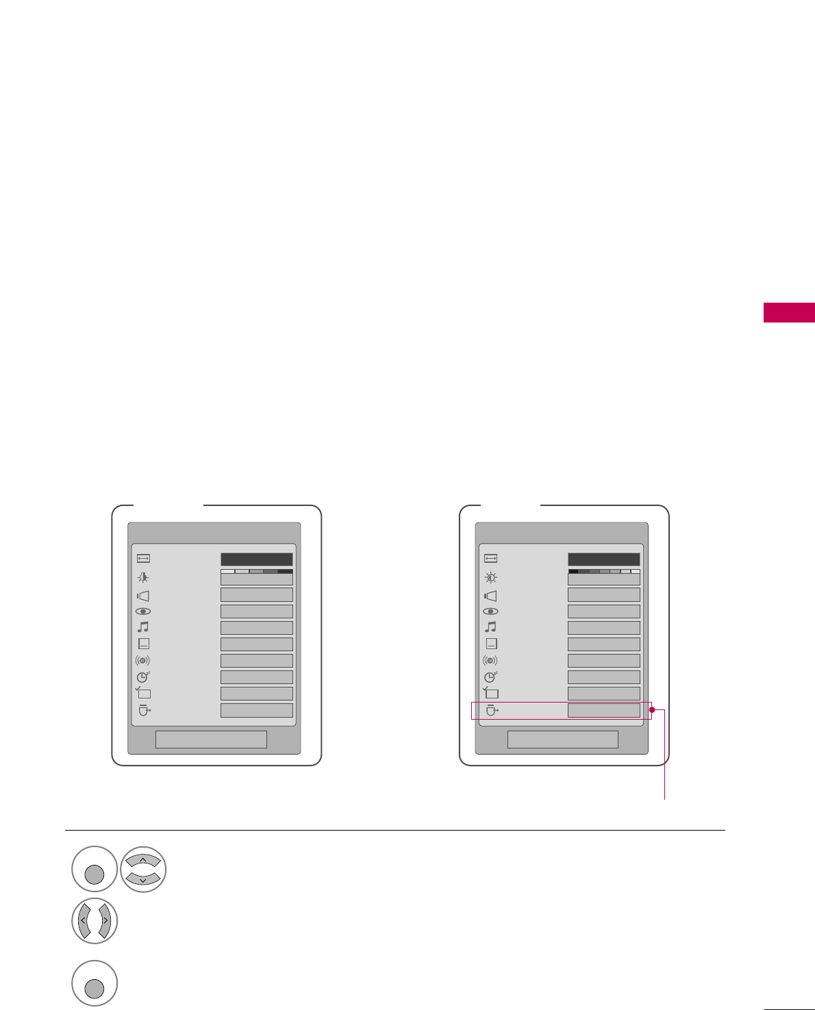
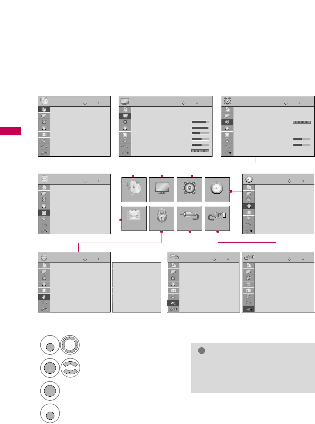
ON-SCREEN MENUS SELECTION
Your TV's OSD (On Screen Display) may differ slightly from that shown in this manual.
NOTE
!
GGIISSMM MMeetthhoodd, PPoowweerr SSaavviinngg: Only
PPllaassmmaa TTVV.
GGBBaacckklliigghhtt,, PPoowweerr IInnddiiccaattoorr: Only
LLCCDD TTVV.
Display each menu.
Select a menu item.
Enter to the pop up menu.
1
MENU
3
2
ENTER
ENTER
Return to TV viewing.
4
MENU
Enter
Move
Auto Tuning
Manual Tuning
Channel Edit
CHANNEL
CHANNEL
OPTION
PICTURE
LOCK
AUDIO
INPUT
TIME
USB
Enter
Move
Aspect Ratio : 16:9
Picture Mode : Standard
• Backlight 80
• Contrast 90
• Brightness 50
• Sharpness 60
• Color 60
• Tint 0
PICTURE
E
Enter
Move
Auto Volume : Off
Clear Voice : On
Balance 0
Sound Mode : Standard
•
SRS TruSurround XT:
Off
• Treble 50
• Bass 50
• Reset
AUDIO
E
LR
Enter
Move
Clock :
Feb/21/2008 2:10 AM
Off Time : Off
On Time : Off
Sleep Timer : Off
Auto Sleep : Off
TIME
Enter
Move
PHOTO LIST
MUSIC LIST
USB
Enter
Move
Antenna
Cable
AV1
AV2
Component1
Component2
RGB-PC
HDMI1
INPUT
E
Enter
Move
Lock System : Off
Set Password
Block Channel
Movie Rating
TV Rating-Children
TV Rating-General
Downloadable Rating
Input Block
LOCK
Lock System : Off
Set Password
Block Channel
TV Rating-English
TV Rating-French
Downloadable Rating
Input Block
Enter
Move
Language : English
Input Label
SIMPLINK : On
Key Lock : Off
Caption : Off
ISM Method : Normal
Power Saving : Level 0
Set ID : 1
OPTION
For USA For Canada
E
All models (Except 32/37/42LG30DC)
RG
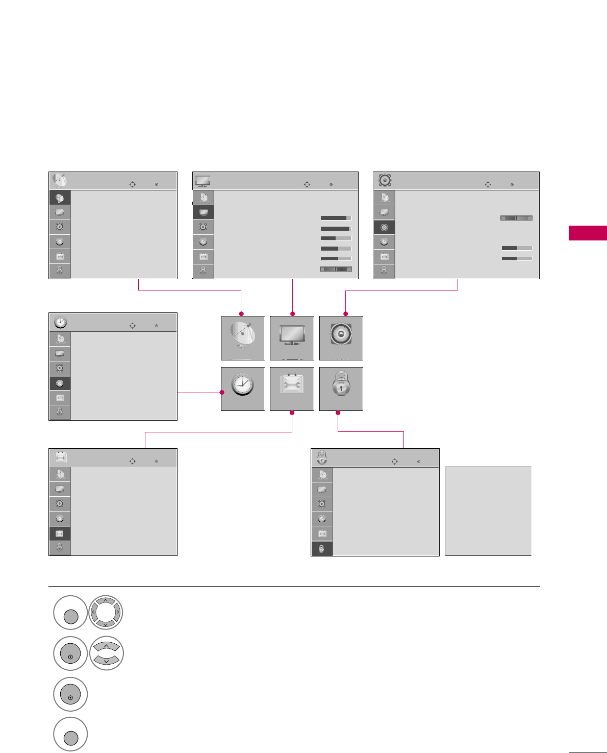
WATCHING TV / CHANNEL CONTROL
51
Only for 32/37/42LG30DC
Display each menu.
Select a menu item.
Enter to the pop up menu.
1
MENU
3
2
ENTER
ENTER
Return to TV viewing.
4
MENU
Enter
Move
Auto Tuning
Manual Tuning
Channel Edit
CHANNEL
CHANNEL
TIME
PICTURE
OPTION
AUDIO
LOCK
Enter
Move
Aspect Ratio : 16:9
Picture Mode : Standard
• Backlight 80
• Contrast 90
• Brightness 50
• Sharpness 60
• Color 60
• Tint 0
PICTURE
E
Enter
Move
Auto Volume : Off
Clear Voice : On
Balance 0
Sound Mode : Standard
•
SRS TruSurround XT:
Off
• Treble 50
• Bass 50
• Reset
AUDIO
E
LR
Enter
Move
Clock :
Feb/21/2008 2:10 AM
Off Time : Off
On Time : Off
Sleep Timer : Off
Auto Sleep : Off
TIME
Enter
Move
Lock System : Off
Set Password
Block Channel
Movie Rating
TV Rating-Children
TV Rating-General
Downloadable Rating
Input Block
LOCK
Enter
Move
Language : English
Input Label
SIMPLINK : On
Key Lock : Off
Caption : Off
Set ID : 1
Power Indicator
Initial Setting : Home
OPTION
Lock System : Off
Set Password
Block Channel
TV Rating-English
TV Rating-French
Downloadable Rating
Input Block
For USA For Canada
RG
WATCHING TV / CHANNEL CONTROL
52
WATCHING TV / CHANNEL CONTROL
CHANNEL SETUP
Auto Scan (Auto Tuning)
Automatically finds all channels available through antenna or cable inputs, and stores them in memory on the
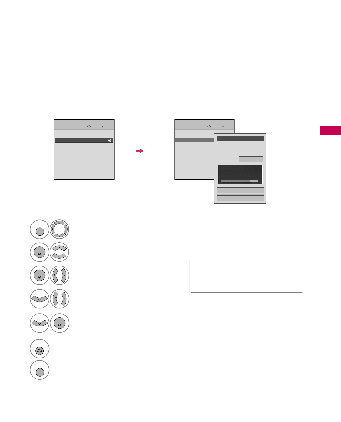
channel list.
Run Auto Tuning again after any Antenna/Cable connection changes.
Select CCHHAANNNNEELL.
Select AAuuttoo TTuunniinngg.
Select YYeess.
Run AAuuttoo ttuunniinngg.
Enter
Move
CHANNEL
Enter
Move
CHANNEL
1
MENU
3
2
ENTER
ENTER
4
ENTER
Auto Tuning
Manual Tuning
Channel Edit
Auto Tuning
Manual Tuning
Channel Edit
Press ‘Yes’ button to begin
auto tuning.
Yes
No
■A password is required to gain access to
Auto Tuning menu if the Lock System is
turned on.
5
RETURN
Return to the previous menu.
MENU
Return to TV viewing.
WATCHING TV / CHANNEL CONTROL
53
Select CCHHAANNNNEELL.
1
MENU
2
ENTER
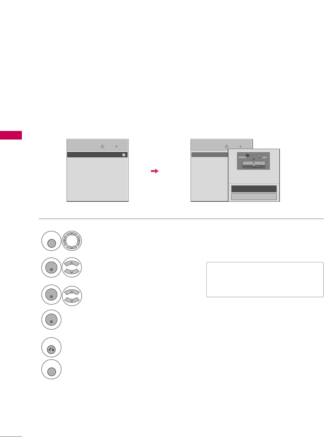
If selecting DTV or CADTV input signal, you can view the on-screen signal strength monitor to see the quality
of the signal being received.
Add/Delete Channel (Manual Tuning)
Enter
Move
CHANNEL
Enter
Move
CHANNEL
Channel
Select channel type and
RF-channel number.
FF
DTV
GG
2
Close
Delete
Auto Tuning
Manual Tuning
Channel Edit
DTV 2-1
Bad Normal Good
Select MMaannuuaall TTuunniinngg.
Select DDTTVV, TTVV, CCAADDTTVV, or CCAATTVV.
Select channel you want to add
or delete.
3
ENTER
4
Select AAdddd or DDeelleettee.
5
ENTER
Auto Tuning
Manual Tuning
Channel Edit
■A password is required to gain access to
Manual Tuning menu if the Lock System
is turned on.
6
RETURN
Return to the previous menu.
MENU
Return to TV viewing.
WATCHING TV / CHANNEL CONTROL
54
WATCHING TV / CHANNEL CONTROL
CHANNEL SETUP
Select a channel.
Select channel you want to add or
delete.
3
ENTER
4
ENTER
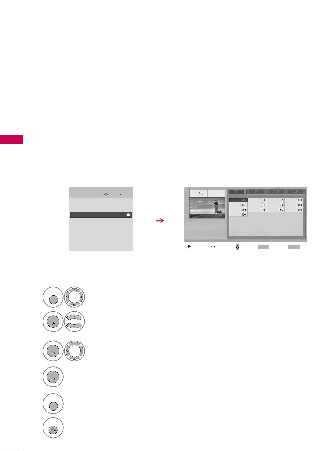
A custom list can be created by toggling each channel on or off with ENTER button. The channels in the Custom
List are displayed in black and the channels deleted from the Custom List are displayed in gray.
Once a channel is highlighted you can add or delete the channel by referring to the small window at the top-
right corner of the screen.
Channel Editing
Enter
Move
CHANNEL
Auto Tuning
Manual Tuning
Channel Edit
Select CCHHAANNNNEELL.
1
MENU
2
ENTER
Select CChhaannnneell EEddiitt.
RETURN
Return to TV viewing.
Return to the previous menu.
5
MENU
Add/Delete Move Page
CH
Move Previous
MENU Exit
RETURN
WATCHING TV / CHANNEL CONTROL
55
INPUT LIST
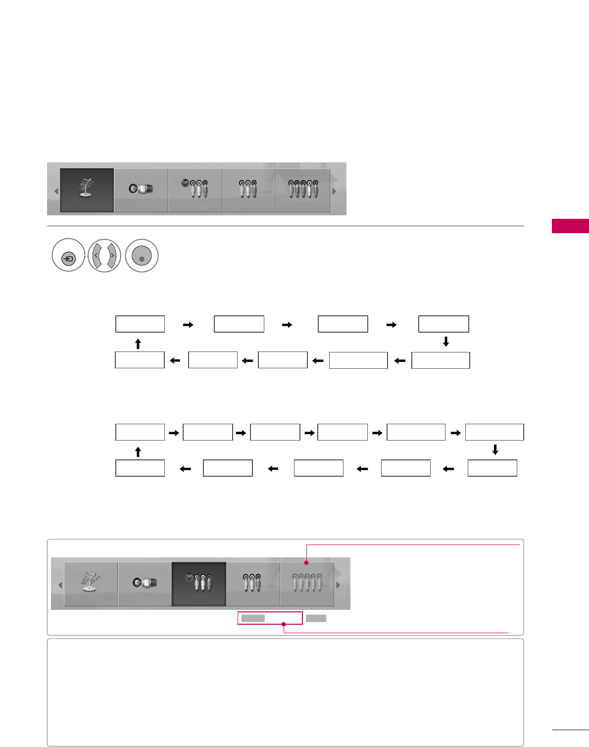
Only these input signals which are connected to a TV can be activated and selected.
Select the desired input source.
■You can also select the desired input source in the IINNPPUUTT menu
(Except 32/37/42LG30DC).
1
INPUT
Antenna Cable AV1 AV2
HDMI2 HDMI1 RGB-PC Component2 Component1
Antenna Cable AV1 AV2 Component1
ENTER
■AAnntteennnnaa: Select it to watch over-the-air broadcasts.
■CCaabbllee: Select it to watch cable and digital cable.
■AAVV: Select them to watch a VCR or other external equipment.
■CCoommppoonneenntt: Select them to watch DVD or a Digital set-top box.
■RRGGBB--PPCC: Select it to view PC input.
■HHDDMMII: Select them to watch high definition devices.
Antenna Cable AV1 AV2 Component1
Input Label
Q.MENU Exit
RETURN
Select a desired input source (except
AAnntteennnnaaor CCaabbllee). Then, you can select
your desired Input Label with using Q. MENU
button. GGpp..6600
Disconnected inputs are inactive (grayed out)
ie)
LCD TV
Antenna Cable AV1 AV2 Component1
HDMI4 HDMI3 HDMI2 HDMI1 RGB-PC
Component2
Plasma TV
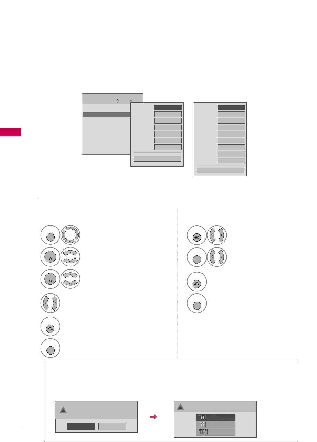
WATCHING TV / CHANNEL CONTROL
56
WATCHING TV / CHANNEL CONTROL
INPUT LABEL
You can set a label for each input source when it's not in use.
Enter
Move
OPTION
Language : English
Input Label
SIMPLINK : On
Key Lock : Off
Caption : Off
ISM Method : Normal
Power Saving : Level 0
Set ID : 1
EE
Select OOPPTTIIOONN.
Select IInnppuutt LLaabbeell.
Select the label.
1
MENU
2
ENTER
Select the source.
3
ENTER
4
5
RETURN
Return to the previous menu.
MENU
Return to TV viewing.
With using OPTION menu
Select the source.
Select the label.
1
INPUT
2
Q. MENU
3
RETURN
Return to the previous menu.
MENU
Return to TV viewing.
With using INPUT button
■When new external device is connected, this popup menu is displayed automatically.
If selecting YYeess, you can select input source that you want to appreciate.
■But, when selecting “SSIIMMPPLLIINNKK- OOnn”, popup menu for HDMI input will not be displayed.
No
Yes
!New external device is connected.
Do you want to enjoy this?
!
Select input source that you want to appreciate.
AV1
AV2
Component1
AV1 FFGG
AV2
Component1
HDMI1
RGB-PC
Component2
HDMI2
Close
AV1 FFGG
AV2
Component1
HDMI1
RGB-PC
Component2
HDMI2
HDMI3
HDMI4
Close
Plasma TV
LCD TV
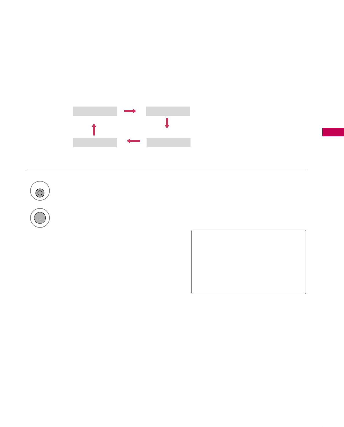
WATCHING TV / CHANNEL CONTROL
57
AV MODE
You can select the optimal images and sounds.
1
AV MODE
2
Off Cinema
Game Sport
Press the AAVV MMOODDEEbutton repeatedly to select the desired source.
ENTER
■If you select “CCiinneemmaa” in AV mode,
CCiinneemmaa will be selected both for “PIC-
TURE menu - Picture Mode” and “AUDIO
menu - Sound Mode” respectively.
■If you select “OOffff” in AV mode, the
“PPiiccttuurree MMooddee” and “SSoouunndd MMooddee”
return to previous selected value.
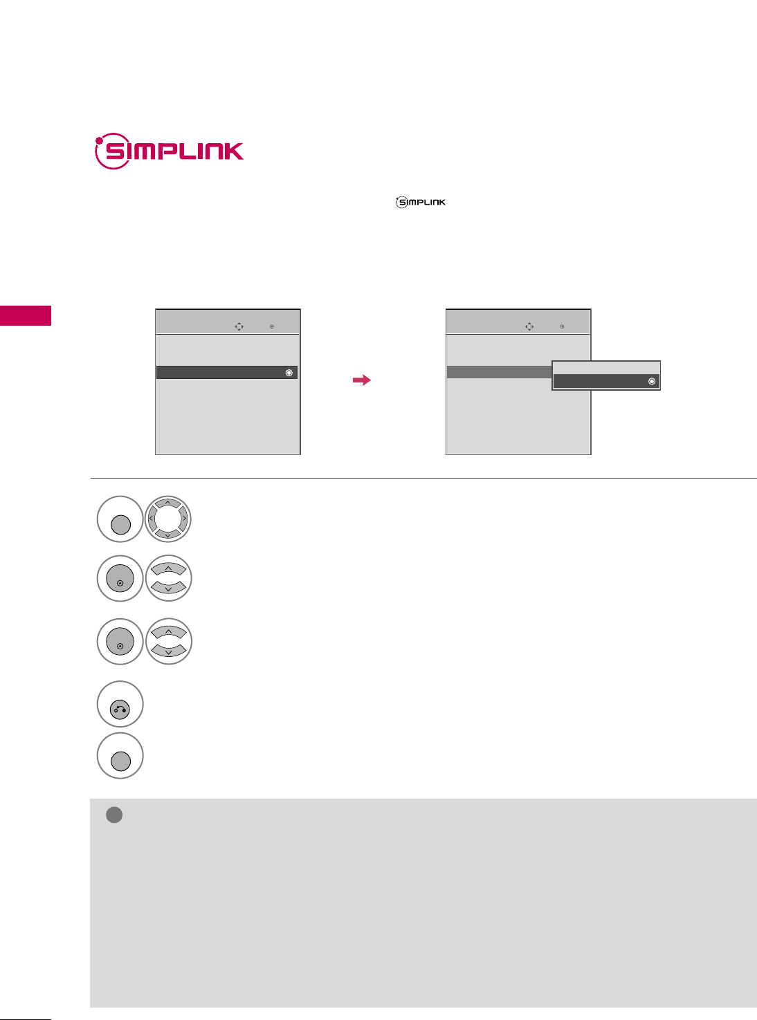
WATCHING TV / CHANNEL CONTROL
58
WATCHING TV / CHANNEL CONTROL
This function operates only with devices with the logo.
The TV might not function properly when using it with other products with HDMI-CEC function.
This allows you to control and play other AV devices connected with HDMI cable without additional cables and
settings.
To start using SIMPLINK, turn it on in the user menus.
Enter
Move
OPTION
Select OOPPTTIIOONN.
Select SSIIMMPPLLIINNKK.
Select OOnn or OOffff.
Enter
Move
OPTION
E
1
MENU
3
2
ENTER
ENTER
Language : English
Input Label
SIMPLINK : On
Key Lock : Off
Caption : Off
ISM Method : Normal
Power Saving : Level 0
Set ID : 1
Language : English
Input Label
SIMPLINK : On
Key Lock : Off
Caption : Off
ISM Method : Normal
Power Saving : Level 0
Set ID : 1
Off
On
NOTE
!
GGConnect the HDMI/DVI IN or HDMI IN terminal of the TV to the rear terminal (HDMI terminal) of the
SIMPLINK device with the HDMI cable.
GGWhen you switch the Input source with the INPUT button on the remote control, the SIMPLINK device
will stop.
GGWhen you select a device with home theater functionality, the sound output automatically switches to
the home theater speakers.
GGIf a connected SIMPLINK home theater system doesn't play the audio from the TV, connect the DIGITAL
AUDIO OUT terminal on the back of the TV to the DIGITAL AUDIO IN terminal on the back of the SIM-
PLINK device with an OPTICAL cable.
E
4
RETURN
Return to the previous menu.
MENU
Return to TV viewing.
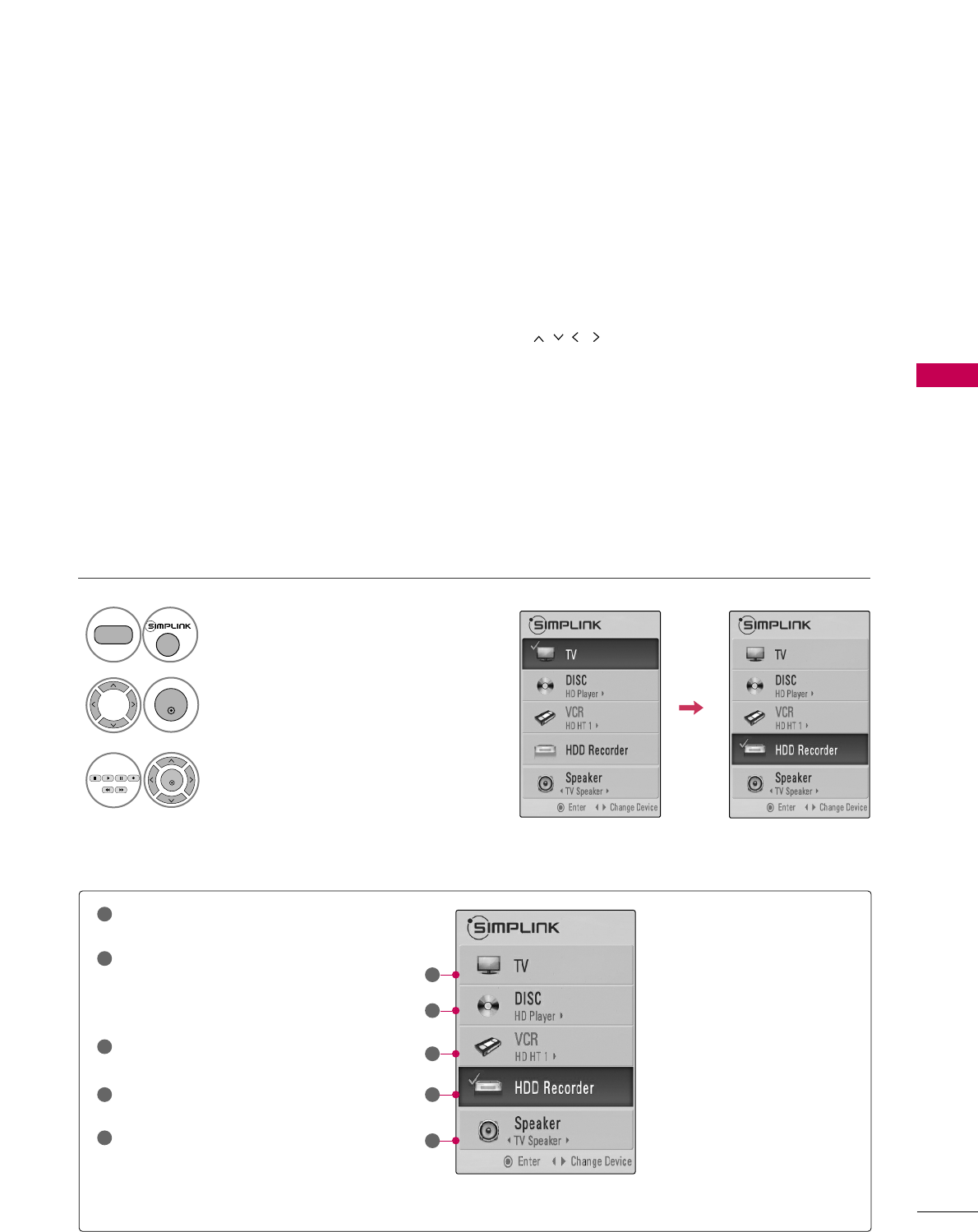
WATCHING TV / CHANNEL CONTROL
59
■DDiirreecctt PPllaayy:: After connecting AV devices to the TV, you can directly control the devices and play media with-
out additional settings.
■SSeelleecctt AAVV ddeevviiccee:: Enables you to select one of the AV devices connected to TV.
■DDiisscc ppllaayybbaacckk:: Control connected AV devices by pressing the ,
ENTER,
G
,
A
, ll ll
,
FF and GG buttons.
■PPoowweerr ooffff aallll ddeevviicceess:: When you power off the TV, all connected devices are turned off.
■SSwwiittcchh aauuddiioo--oouutt:: Offers an easy way to switch audio-out.
■SSyynncc PPoowweerr oonn:: When you play the connected AV device, TV will automatically turn on.
(A device, which is connected to the TV through a HDMI cable but does not support SIMPLINK, does not provide
this function)
Note: To operate SIMPLINK, an HDMI cable over Version 1.2 with *CEC function should be used. (*CEC: Consumer
Electronics Control).
SIMPLINK Menu
TTVV vviieewwiinngg: Switch to the previous TV
channel regardless of the current mode.
DDIISSCC ppllaayybbaacckk: Select and play discs.
When multiple discs are available, the titles
of discs are conveniently displayed at the
bottom of the screen.
VVCCRR ppllaayybbaacckk: Control the connected
VCR.
HHDDDD RReeccoorrddiinnggss ppllaayybbaacckk: Control
recordings stored in HDD.
AAuuddiioo OOuutt ttoo HHoommee TThheeaatteerr ssppeeaakk--
eerr//AAuuddiioo OOuutt ttoo TTVV: Select Home
Theater speaker or TV speaker for Audio
Out.
SIMPLINK Functions
1
2
3
4
5
GG
When no device is connected
(displayed in gray)
GG
Selected Device
GG
When a device is connected
(displayed in bright color)
1
2
3
4
5
Display SSIIMMPPLLIINNKK menu.
Select the desired device.
Control connected AV devices.
1
TV
3
2
ENTER
ENTER
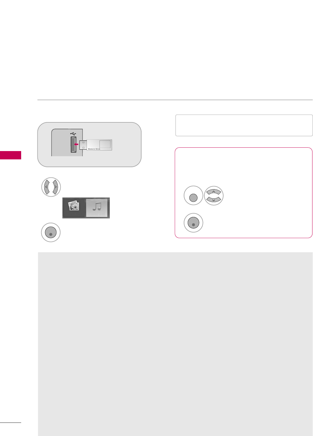
USB
60
USB
ENTRY MODES
When you connect a USB device, this screen is displayed automatically.
In USB device, you can not add a new folder or delete the existing folder.
Precautions when using the USB device
GGOnly a USB storage device is recognizable.
GGIf the USB storage device is connected through a
USB hub, the device is not recognizable.
GGA USB storage device using an automatic recogni-
tion program may not be recognized.
GGA USB storage device which uses its own driver
may not be recognized.
GGIn case of a card reader, up to four memory cards
are concurrently recognizable.
GGThe recognition speed of a USB storage device
may depend on each device.
GGPlease do not turn off the TV or unplug the USB
device when the connected USB storage device is
working. When such device is suddenly separated
or unplugged, the stored files or the USB storage
device may be damaged.
GGPlease do not connect the USB storage device
which was artificially maneuvered on the PC. The
device may cause the product to malfunction or
fail to be played. Never forget to use only a USB
storage device which has normal music files or
image files.
GGPlease use only a USB storage device which was
formatted as a FAT or NTFS file system provided
with the Windows operating system. In case of a
storage device formatted as a different utility pro-
gram which is not supported by Windows, it may
not be recognized.
GGPlease connect power to a USB storage device
which requires an external power supply. If not,
the device may not be recognized.
GGPlease connect a USB storage device with cable is
offered by USB maker. If connected with cable is
not offered by USB maker or an excessively long
cable, the device may not be recognized.
GGSome USB storage devices may not be supported
or operated smoothly.
GGFile alignment method of USB storage device is
similar to Window XP and filename can recognize
up to 100 English characters.
GGPlease backup important files because data on
USB device may be damaged. Data management is
consumer's responsibility and as a result, the man-
ufacturer does not cover data damage.
When removing the USB device
Connect the USB device to the UUSSBB IINN
jacks on the side of TV.
3
Select PPHHOOTTOO LLIISSTT or MMUUSSIICCLLIISSTT
1
USB IN
PHOTO LIST MUSIC LIST
Select UUSSBB EEjjeecctt.
Select the UUSSBB EEjjeeccttmenu before removing the
USB device.
2
ENTER
1
Q. MENU
2
ENTER
* Except 32/37/42LG30DC
■It doesn’t support USB HDD
■This TV supports JPG and MP3.