LG Electronics USA 42LG50UA LCD TV MONITOR User Manual User s Manual H ok
LG Electronics USA LCD TV MONITOR User s Manual H ok
USERS MANUAL

EUT Type: LCD TV/Monitor
FCC ID: BEJ42LG50UA
Test Report No.: GETEC-E3-07-089
FCC Class B Certification
APPENDIX H
: USER’S MANUAL
Please read this manual carefully before operating
your set.
Retain it for future reference.
Record model number and serial number of the set.
See the label attached on the back cover and quote
this information to your dealer
when you require service.
LCD TV PLASMA TV
OWNER’S MANUAL
LCD TV MODEL
26LG30 37LG50
32LG30 42LG50
37LG30 47LG50
42LG30 52LG50
32LG60 32LG70
37LG60 42LG70
42LG60 47LG70
47LG60 52LG70
52LG60
PLASMA TV MODELS
42PG10 50PG60F
50PG10 60PG60F
42PG20 42PG20C
50PG20 50PG20C
P/NO : SAC30708020 (0711-REV00)
www.lgusa.com / www.lg.ca / www.lgcommercial.com
As an ENERGY STAR
Partner LGE U. S. A.,Inc.
has determined that this
product meets the
ENERGY STAR guidelines
for energy efficiency.
ENERGY STAR is a set of power-saving
guidelines issued by the U.S.
Environmental Protection Agency(EPA).
1
WARNING / CAUTION
WARNING / CAUTION
To prevent fire or shock hazards, do not expose
this product to rain or moisture.
FCC NOTICE
Class B digital device
This equipment has been tested and found to comply
with the limits for a Class B digital device, pursuant to
Part 15 of the FCC Rules. These limits are designed
to provide reasonable protection against harmful
interference in a residential installation. This equipment
generates, uses and can radiate radio frequency energy
and, if not installed and used in accordance with the
instructions, may cause harmful interference to radio
communications. However, there is no guarantee that
interference will not occur in a particular installation.
If this equipment does cause harmful interference to
radio or television reception, which can be determined
by turning the equipment off and on, the user is
encouraged to try to correct the interference by one
or more of the following measures:
- Reorient or relocate the receiving antenna.
- Increase the separation between the equipment and
receiver.
- Connect the equipment to an outlet on a circuit
different from that to which the receiver is connected.
- Consult the dealer or an experienced radio/TV
technician for help.
Any changes or modifications not expressly approved
by the party responsible for compliance could void
the user’s authority to operate the equipment.
CAUTION
Do not attempt to modify this product in any way
without written authorization from LG Electronics.
Unauthorized modification could void the user’s
authority to operate this product
The lightning flash with arrowhead
symbol, within an equilateral triangle, is
intended to alert the user to the presence
of uninsulated “dangerous voltage” within the
product’s enclosure that may be of sufficient
magnitude to constitute a risk of electric shock to
persons.
The exclamation point within an equilateral
triangle is intended to alert the user to
the presence of important operating and
maintenance (servicing) instructions in the litera-
ture accompanying the appliance.
TO REDUCE THE RISK OF ELECTRIC SHOCK
DO NOT REMOVE COVER (OR BACK). NO
USER SERVICEABLE PARTS INSIDE. REFER TO
QUALIFIED SERVICE PERSONNEL.
WARNING/CAUTION
TO REDUCE THE RISK OF FIRE AND ELECTRIC
SHOCK, DO NOT EXPOSE THIS PRODUCT TO
RAIN OR MOISTURE.
NOTE TO CABLE/TV INSTALLER
This reminder is provided to call the CATV system
installer’s attention to Article 820-40 of the National
Electric Code (U.S.A.). The code provides guidelines for
proper grounding and, in particular, specifies that the
cable ground shall be connected to the grounding system
of the building, as close to the point of the cable entry
as practical.
2
IMPORTANT SAFETY INSTRUCTIONS
SAFETY INSTRUCTIONS
Important safety instructions shall be provided with each apparatus. This information shall be given in a separate
booklet or sheet, or be located before any operating instructions in an instruction for installation for use and
supplied with the apparatus.
This information shall be given in a language acceptable to the country where the apparatus is intended to be used.
The important safety instructions shall be entitled “Important Safety Instructions”. The following safety
instructions shall be included where applicable, and, when used, shall be verbatim as follows. Additional safety
information may be included by adding statements after the end of the following safety instruction list. At the
manufacturer’s option, a picture or drawing that illustrates the intent of a specific safety instruction may be
placed immediately adjacent to that safety instruction:
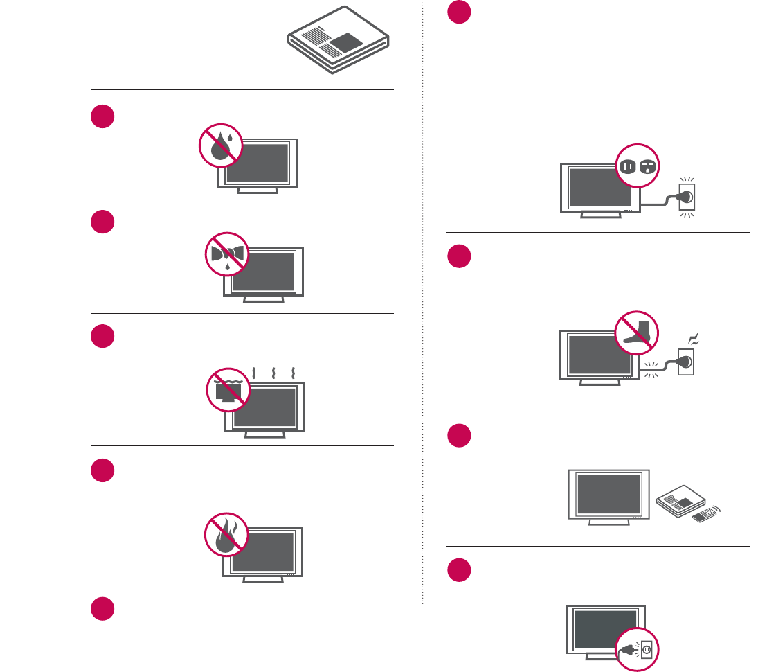
Read these instructions.
Keep these instructions.
Heed all warnings.
Follow all instructions.
Do not use this apparatus near water.
Clean only with dry cloth.
Do not block any ventilation openings. Install in
accordance with the manufacturer’s instructions.
Do not install near any heat sources such as
radiators, heat registers, stoves, or other apparatus
(including amplifiers)that produce heat.
When mounting a TV it on the wall, make sure
not to install TV by hanging power and signal
cables on the back of the TV.
Do not defeat the safety purpose of the polarized
or grounding-type plug. A polarized plug has
two blades with one wider than the other. A
grounding type plug has two blades and a third
grounding prong, The wide blade or the third
prong are provided for your safety. If the provided
plug does not fit into your outlet, consult an
electrician for replacement of the obsolete outlet.
Protect the power cord from being walked on
or pinched particularly at plugs, convenience
receptacles, and the point where they exit from
the apparatus.
Only use attachments/accessories specified by
the manufacturer.
Unplug this apparatus when unused for long
periods of time.
1
2
3
4
5
6
7
8
9
3
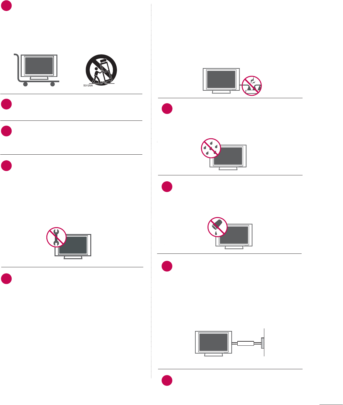
Use only with the cart, stand, tripod, bracket,
or table specified by the manufacturer, or sold
with the apparatus. When a cart is used, use
caution when moving the cart/apparatus
combination to avoid injury from tip-over.
Never touch this apparatus or antenna during
a thunder or lighting storm.
Do not allow a impact shock or any objects to
fall into the product, and do not drop onto the
screen with something.
Refer all servicing to qualified service personnel.
Servicing is required when the apparatus has
been damaged in any way, such as power-supply
cord or plug is damaged, liquid has been
spilled or objects have fallen into the apparatus,
the apparatus has exposed to rain or moisture,
does not operate normally, or has been
dropped.
CAUTION concerning the Power Cord :
Most appliances recommend they be placed
upon a dedicated circuit; that is, a single outlet
circuit which powers only that appliance and
has no additional outlets or branch circuits.
Check the specification page of this owner's
manual to be certain.
Do not overload wall outlets. Overloaded wall
outlets, loose or damaged wall outlets, extension
cords, frayed power cords, or damaged or
cracked wire insulation are dangerous. Any of
these conditions could result in electric shock
or fire. Periodically examine the cord of your
appliance, and if its appearance indicates dam-
age or deterioration, unplug it, discontinue use
of the appliance, and have the cord replaced
with an exact replacement part by an authorized
servicer. Protect the power cord from physical
or mechanical abuse, such as being twisted,
kinked, pinched, closed in a door, or walked
upon. Pay particular attention to plugs, wall
outlets, and the point where the cord exits the
appliance.
Outdoor use marking :
WARNING - To reduce the risk of fire or elec-
tric shock, do not expose this appliance to rain
or moisture.
Wet Location Marking : Apparatus shall not be
exposed to dripping or splashing and no
objects filled with liquids, such as vases, shall
be placed on or over apparatus.
GROUNDING
Ensure that you connect the earth ground wire
to prevent possible electric shock. If grounding
methods are not possible, have a qualified
electrician install a separate circuit breaker.
Do not try to ground the unit by connecting it
to telephone wires, lightening rods, or gas pipes.
DISCONNECTING D
D
EVICE F
F
ROM M
M
AINS
Mains plug is the disconnecting device. The
plug must remain readily operable.
12
10
11
14
13
15
16
17
18
Power
Supply
Short-circuit
Breaker

4
CONTENTS
WARNING / CAUTION
. . . . . . . . . . . . . . . . . . . . . . . . . . . . 1
SAFETY INSTRUCTIONS
. . . . . . . . . . . . . . . . . . . . . . . . . . 2
FEATURE OF THIS TV
. . . . . . . . . . . . . . . . . . . . . . . . . . . . . . . 6
PREPARATION
Accessories . . . . . . . . . . . . . . . . . . . . . . . . . . . . . . . . . . . . . . . . . . . . . . . . . . . . . . 7
Front Panel Information . . . . . . . . . . . . . . . . . . . . . . . . . . . . . . . . . . . . . 8
Back Panel Information . . . . . . . . . . . . . . . . . . . . . . . . . . . . . . . . . . . . 10
Stand Installation . . . . . . . . . . . . . . . . . . . . . . . . . . . . . . . . . . . . . . . . . . . . 14
Back Cover for Wire Arrangement . . . . . . . . . . . . . . . . . . . . . 16
Desktop Pedestal Installation . . . . . . . . . . . . . . . . . . . . . . . . . . . . 18
VESA Wall Mounting . . . . . . . . . . . . . . . . . . . . . . . . . . . . . . . . . . . . . . . . 18
Swivel Stand . . . . . . . . . . . . . . . . . . . . . . . . . . . . . . . . . . . . . . . . . . . . . . . . . . . . 19
Not Using the Desk-Type Stand . . . . . . . . . . . . . . . . . . . . . . . . 19
Attaching the TV to a Desk . . . . . . . . . . . . . . . . . . . . . . . . . . . . . . 19
How to join the TV Assemble to the wall to protect
the TV tumbling . . . . . . . . . . . . . . . . . . . . . . . . . . . . . . . . . . . . . . . . . . . . . . 20
Antenna or Cable Connection . . . . . . . . . . . . . . . . . . . . . . . . . . 21
EXTERNAL EQUIPMENT SETUP
HD Receiver Setup . . . . . . . . . . . . . . . . . . . . . . . . . . . . . . . . . . . . . . . . . 22
DVD Setup . . . . . . . . . . . . . . . . . . . . . . . . . . . . . . . . . . . . . . . . . . . . . . . . . . . . . 25
VCR Setup . . . . . . . . . . . . . . . . . . . . . . . . . . . . . . . . . . . . . . . . . . . . . . . . . . . . . 27
Other A/V Source Setup . . . . . . . . . . . . . . . . . . . . . . . . . . . . . . . . . 29
PC Setup . . . . . . . . . . . . . . . . . . . . . . . . . . . . . . . . . . . . . . . . . . . . . . . . . . . . . . . . 30
USB In Setup . . . . . . . . . . . . . . . . . . . . . . . . . . . . . . . . . . . . . . . . . . . . . . . . . 38
Audio Out Setup . . . . . . . . . . . . . . . . . . . . . . . . . . . . . . . . . . . . . . . . . . . . 39
WATCHING TV / CHANNEL CONTROL
Remote Control Functions . . . . . . . . . . . . . . . . . . . . . . . . . . . . . . . 40
Turning On TV . . . . . . . . . . . . . . . . . . . . . . . . . . . . . . . . . . . . . . . . . . . . . . . . 42
Channel Selection . . . . . . . . . . . . . . . . . . . . . . . . . . . . . . . . . . . . . . . . . . . 42
Volume Adjustment . . . . . . . . . . . . . . . . . . . . . . . . . . . . . . . . . . . . . . . . . 42
Quick Menu . . . . . . . . . . . . . . . . . . . . . . . . . . . . . . . . . . . . . . . . . . . . . . . . . . . . 43
Installation Guide . . . . . . . . . . . . . . . . . . . . . . . . . . . . . . . . . . . . . . . . . . . . 44
On-Screen Menus Selection . . . . . . . . . . . . . . . . . . . . . . . . . . . . 46
Channel Setup
- Auto Scan (Auto Tuning) . . . . . . . . . . . . . . . . . . . . . . . . . . . 48
- Add / Delete Channel (Manual Tuning) . . . . . . 49
- Channel Editing . . . . . . . . . . . . . . . . . . . . . . . . . . . . . . . . . . . . . . . . 50
Input List . . . . . . . . . . . . . . . . . . . . . . . . . . . . . . . . . . . . . . . . . . . . . . . . . . . . . . . . 51
Input Label . . . . . . . . . . . . . . . . . . . . . . . . . . . . . . . . . . . . . . . . . . . . . . . . . . . . . 52
AV Mode . . . . . . . . . . . . . . . . . . . . . . . . . . . . . . . . . . . . . . . . . . . . . . . . . . . . . . . . 53
SimpLink . . . . . . . . . . . . . . . . . . . . . . . . . . . . . . . . . . . . . . . . . . . . . . . . . . . . . . . . . 54
USB
Entry Modes . . . . . . . . . . . . . . . . . . . . . . . . . . . . . . . . . . . . . . . . . . . . . . . . . . . 56
Photo List . . . . . . . . . . . . . . . . . . . . . . . . . . . . . . . . . . . . . . . . . . . . . . . . . . . . . . . 57
Music List . . . . . . . . . . . . . . . . . . . . . . . . . . . . . . . . . . . . . . . . . . . . . . . . . . . . . . . 61
PICTURE CONTROL
Picture Size (Aspect Ratio) Control . . . . . . . . . . . . . . . . . . 64
Preset Picture Settings
- Picture Mode - Preset . . . . . . . . . . . . . . . . . . . . . . . . . . . . . . . 66
- Color Tone - Preset . . . . . . . . . . . . . . . . . . . . . . . . . . . . . . . . . . . 67
Manual Picture Adjustment
- Picture Mode - User Mode . . . . . . . . . . . . . . . . . . . . . . . . 68
- Color Tone - User Mode . . . . . . . . . . . . . . . . . . . . . . . . . . . 69
Picture Improvement Technology . . . . . . . . . . . . . . . . . . . . . 70
Advanced - Black (Darkness) Level . . . . . . . . . . . . . . . . . . . 71
Advanced - Eye Care . . . . . . . . . . . . . . . . . . . . . . . . . . . . . . . . . . . . . . . 72
Advanced - Film Mode . . . . . . . . . . . . . . . . . . . . . . . . . . . . . . . . . . . . . 73
Advanced - TruMotion . . . . . . . . . . . . . . . . . . . . . . . . . . . . . . . . . . . . . 74
TruMotion Demo . . . . . . . . . . . . . . . . . . . . . . . . . . . . . . . . . . . . . . . . . . . . . 75
Picture Reset . . . . . . . . . . . . . . . . . . . . . . . . . . . . . . . . . . . . . . . . . . . . . . . . . . 76
Power Indicator . . . . . . . . . . . . . . . . . . . . . . . . . . . . . . . . . . . . . . . . . . . . . . 77
Image Sticking Minimization (ISM) Method . . . . . . . 78
Power Saving Picture Mode . . . . . . . . . . . . . . . . . . . . . . . . . . . . . . 76

5
SOUND & LANGUAGE CONTROL
Auto Volume Leveller (Auto Volume) . . . . . . . . . . . . . . . . 80
Preset Sound Setting (Sound Mode) . . . . . . . . . . . . . . . . 81
Sound Setting Adjustment - User Mode . . . . . . . . . . . 82
Clear Voice . . . . . . . . . . . . . . . . . . . . . . . . . . . . . . . . . . . . . . . . . . . . . . . . . . . . . 83
Balance . . . . . . . . . . . . . . . . . . . . . . . . . . . . . . . . . . . . . . . . . . . . . . . . . . . . . . . . . . 84
TV Speakers On/Off Setup . . . . . . . . . . . . . . . . . . . . . . . . . . . . . . 85
Audio Reset . . . . . . . . . . . . . . . . . . . . . . . . . . . . . . . . . . . . . . . . . . . . . . . . . . . 86
Stereo/SAP Broadcasts Setup . . . . . . . . . . . . . . . . . . . . . . . . . . 87
Audio Language . . . . . . . . . . . . . . . . . . . . . . . . . . . . . . . . . . . . . . . . . . . . . . 88
On-Screen Menus Language Selection . . . . . . . . . . . . . 89
Caption Mode
- Analog Broadcasting System Captions . . . . . . . 90
- Digital Broadcasting System Captions . . . . . . . . 91
- Caption Option . . . . . . . . . . . . . . . . . . . . . . . . . . . . . . . . . . . . . . . 92
TIME SETTING
Clock Setting
- Auto Clock Setup . . . . . . . . . . . . . . . . . . . . . . . . . . . . . . . . . . . . 93
- Manual Clock Setup . . . . . . . . . . . . . . . . . . . . . . . . . . . . . . . . . 94
Auto On/Off Timer Setting . . . . . . . . . . . . . . . . . . . . . . . . . . . . . 95
Sleep Timer Setting . . . . . . . . . . . . . . . . . . . . . . . . . . . . . . . . . . . . . . . . . 96
Auto Shut-off Setting . . . . . . . . . . . . . . . . . . . . . . . . . . . . . . . . . . . . . . . 97
PARENTAL CONTROL / RATINGS
Set Password & Lock System . . . . . . . . . . . . . . . . . . . . . . . . . . . 98
Channel Blocking . . . . . . . . . . . . . . . . . . . . . . . . . . . . . . . . . . . . . . . . . . . 101
Movie & TV Rating . . . . . . . . . . . . . . . . . . . . . . . . . . . . . . . . . . . . . . . . 102
Downloadable Rating . . . . . . . . . . . . . . . . . . . . . . . . . . . . . . . . . . . . . 107
External Input Blocking . . . . . . . . . . . . . . . . . . . . . . . . . . . . . . . . . . 108
Key lock . . . . . . . . . . . . . . . . . . . . . . . . . . . . . . . . . . . . . . . . . . . . . . . . . . . . . . . . 109
APPENDIX
Troubleshooting . . . . . . . . . . . . . . . . . . . . . . . . . . . . . . . . . . . . . . . . . . . . . 110
Maintenance . . . . . . . . . . . . . . . . . . . . . . . . . . . . . . . . . . . . . . . . . . . . . . . . . . 112
Product Specifications . . . . . . . . . . . . . . . . . . . . . . . . . . . . . . . . . . . . 113
Programming the Remote Control . . . . . . . . . . . . . . . . . . 116
IR Codes . . . . . . . . . . . . . . . . . . . . . . . . . . . . . . . . . . . . . . . . . . . . . . . . . . . . . .119
External Control Through RS-232C . . . . . . . . . . . . . . . . .121
6
FEATURE OF THIS TV
is a trademark of SRS Labs, Inc.
TruSurround XT technology is incorporated under
license from SRS Labs, Inc.
LG TV with this logo can play MP3 music from a MP3
player, such as iPOD, and JPEG images from a digital
camera through the USB device.
With HDMI CEC support of LG’s audio/video device
connected to the HDMI (high-definition multimedia
interface), LG TV with this logo works easily with one
remote control.
It has three HDMI ports that connect audio and video
devices with one cable and produces the highest qual-
ity digital images and sound.
It has 2 HDMI ports that connect audio and video
devices with one cable and produces the highest
quality digital images and sound.
Manufactured under license from Dolby Laboratories.
“
Dolby
“and the double-D symbol are trademarks of
Dolby Laboratories.
High-definition television. High-resolution digital tele-
vision broadcast and playback system composed of
roughly a million or more pixels, 16:9 aspect-ratio
screens, and AC3 digital audio. A subset of digital
television, HDTV formats include 1080i and 720p res-
olutions.
LG's own special digital image generator, consisting of
a full digital image processor, six different main picture
quality factors.
FOR LCD TV
■
If the TV feels cold to the touch, there may be a small “flicker” when it is turned on. This is normal, there is
nothing wrong with TV.
■
Some minute dot defects may be visible on the screen, appearing as tiny red, green, or blue spots. However, they
have no adverse effect on the monitor's performance.
■
Avoid touching the LCD screen or holding your finger(s) against it for long periods of time. Doing so may produce
some temporary distortion effects on the screen.
On Disposal
a. The fluorescent lamp used in this product contains a small amount of mercury.
b. Do not dispose of this product with general household waste.
c. Disposal of this product must be carried out in accordance to the regulations of your local authority.
PREPARATION
7
PREPARATION
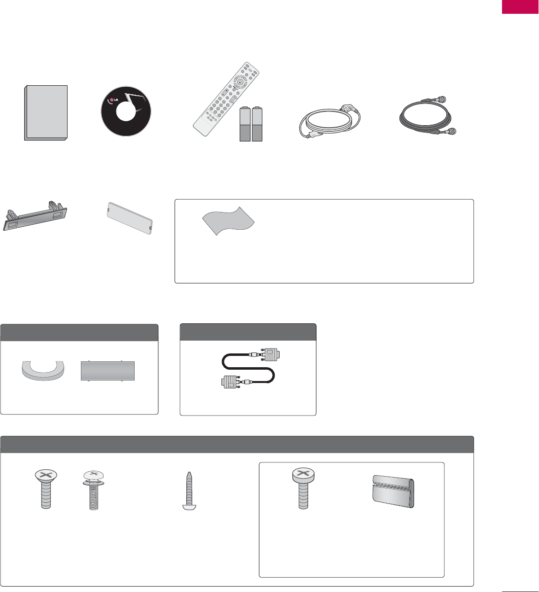
ACCESSORIES
Ensure that the following accessories are included with your product. If an accessory is missing, please contact
the dealer where you purchased the product.
User must use shielded signal interface cables (D-sub 15 pin cable) with ferrite cores to maintain standard
compliance for the product.
The accessories can be different from the figures shown here.
Option E
E
xtras
For L
L
CD T
T
V m
m
odels
Cable Management
Clip
For P
P
lasma T
T
V m
m
odels
Cable Management Clip
Protection Cover
(Refer to P.19)
(This accessories can be different from the figures
shown here depending on your models.)
* Slightly wipe stained spot on the exterior only with the
polishing cloth for the product exterior if there is stain or
fingerprint on surface of the exterior.
* Do not wipe roughly when removing stain. Please be cau-
tions of that excessive pressure may cause scratch or dis-
coloration.
Polishing Cloth
(This feature is not available
for all models.)
Copyright© 2007 LGE,
All Rights Reserved.
D-sub 15 pin Cable
1.5V 1.5V
Owner’s Manual Power Cord 75ohm Round Cable
Remote Control,
Batteries
INPUT
FAV
MUTE
TV
STB
POWER
Q.MENUMENU
AVMODE
RETURN
ENTER
VOLCH
123
456
78
0
9
FLASHBK
P
A
G
E
DVD
VCR
CD Manual
(Only 26/32/37/42LG30,
37/42LG50)
(Only 32/37/42/47/52LG60)(Only 26/32LG30,
32LG50)
Bolts for stand
assembly
(Refer to P.15)
7-Bolts for stand
assembly
(Refer to P.15)
Screw for stand
fixing
(Refer to P.19)
x 4 x 4
or
PREPARATION
8
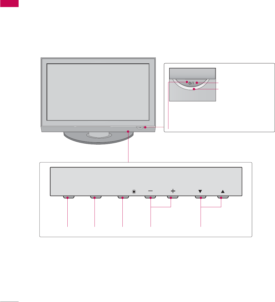
FRONT PANEL INFORMATION
PREPARATION
■
Image shown may differ from your TV
■
NOTE: If your product has a protection tape attached, remove the tape.
And then wipe the product with a cloth (If a polishing cloth is included with your product, use it).
Plasma TV Model
CH
VOL
MENU
INPUT ENTER
INPUT
Button
MENU
Button
ENTER
Button
VOLUME
(-, +) Buttons
CHANNEL
(E,D)Buttons
Remote Control Sensor
POWER Button
Power/Standby Indicator
Illuminates red in standby mode.
Illuminates green when the set is
switched on.
PREPARATION
9
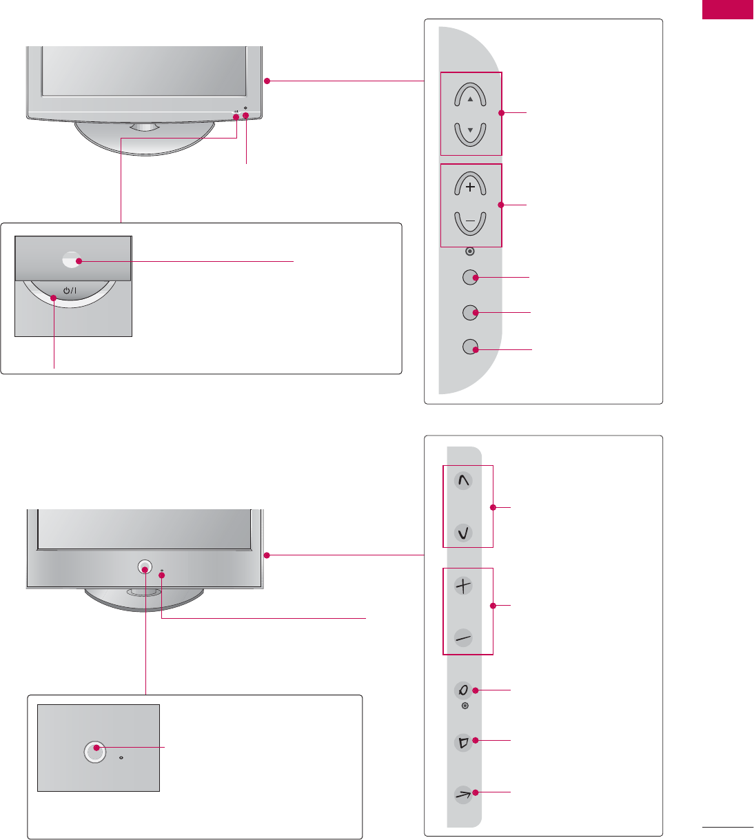
LCD TV Model
POWER Button
Power/Standby Indicator
Illuminates red in standby mode.
Illuminates blue when the set is switched on.
CH
VOL
MENU
INPUT
ENTER
CHANNEL (D,E)
Buttons
VOLUME (+, -)
Buttons
ENTER Button
MENU Button
INPUT Button
Intelligent Eye
Adjusts picture according to the
surrounding conditions
Intelligent Eye (Except **LG30)
Adjusts picture according to the
surrounding conditions
ENTER
CH
VOL
MENU
INPUT
CHANNEL (D,E)
Buttons
VOLUME (+, -)
Buttons
ENTER Button
MENU Button
INPUT Button
26/32/37/42/47/52LG30/50/70
32/37/42/47/52LG60
Remote Control Sensor
Power/Standby Indicator
Illuminates red in standby mode.
Illuminates white when the TV is
switched on.
Note: You can adjust Power
Indicator in the OPTION menu.
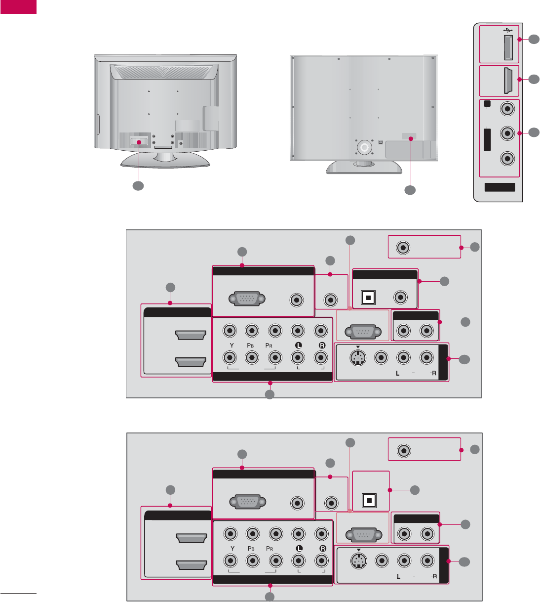
PREPARATION
10
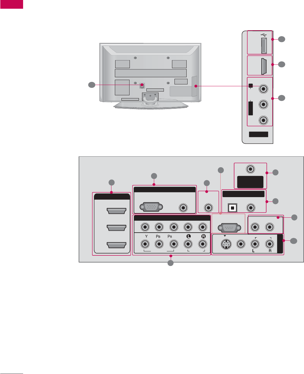
BACK PANEL INFORMATION
PREPARATION
Plasma TV Model
■
Image shown may differ from your TV
AV IN 2
L/MONO
R
AUDIO
VIDEO
USB IN
HDMI IN 4
RGB IN
COMPONENT IN
AUDIO
(RGB/DVI)
RGB(PC)
ANTENNA/
CABLE IN
1
2
RS-232C IN
(CONTROL & SERVICE)
VIDEO
AUDIO
VIDEO
AUDIO OUT
OPTICAL COAXIAL
MONO
( )
AUDIO
S-VIDEO
DIGITAL AUDIO OUT
AV IN 1
HDMI/DVI IN
3
2
1
REMOTE
CONTROL IN
1
3
4
6
7
8
2
11
9
9
5
10
1

PREPARATION
11
HDMI/DVI IN, HDMI IN
Connect a HDMI signal to HDMI port.
Or DVI (VIDEO) signal to the HDMI port with a
DVI to HDMI cable.
COMPONENT IN
Connect a component video/audio device to these
jacks.
RGB (PC)
Connect the output from a PC.
AUDIO (RGB/DVI)
Connect the audio from a PC.
REMOTE CONTROL PORT
Connect your wired remote control.
RS-232C IN (CONTROL & SERVICE) PORT
Connect to the RS-232C port on a PC.
ANTENNA/CABLE IN
Connect over-the air signals to this jack.
Connect cable signals to this jack.
DIGITAL AUDIO OUT
Connect digital audio to various types of equipment.
Note: In standby mode, these ports do not work.
AUDIO OUT
Connect analog audio to various types of equipment.
AV (Audio/Video) IN
Connect audio/video output from an external
device to these jacks.
S-VIDEO
Connect S-Video out from an S-VIDEO device.
USB INPUT
Power Cord Socket
For operation with AC power.
Caution: Never attempt to operate the TV on DC
power.
1
2
3
4
5
6
7
8
9
10
11
PREPARATION
12
PREPARATION
LCD TV Model
AV IN 2
L/MONO
R
AUDIO
VIDEO
USB
SERVUCE ONLY
HDMI IN 3
RGB IN
COMPONENT IN
AUDIO
(RGB/DVI)
RGB(PC)
REMOTE
CONTROL IN
ANTENNA/
CABLE IN
1
2
RS-232C IN
(CONTROL & SERVICE)
VIDEO
AUDIO
OPTICAL COAXIAL
DIGITAL AUDIO OUT
AUDIO OUT
AV IN 1
HDMI/DVI IN
2
1 (DVI)
VIDEO
MONO
( )
AUDIO
S-VIDEO
1
3
4
6
7
8
2
11 11
9
9
5
RGB IN
COMPONENT IN
AUDIO
(RGB/DVI)
RGB(PC)
REMOTE
CONTROL IN
ANTENNA/
CABLE IN
1
2
RS-232C IN
(CONTROL & SERVICE)
VIDEO
AUDIO
DIGITAL
AUDIO OUT
OPTICAL
AUDIO OUT
AV IN 1
HDMI/DVI IN
2
1 (DVI)
VIDEO
MONO
( )
AUDIO
S-VIDEO
1
3
4
6
7
8
2
9
5
10
1
■
Image shown may differ from your TV
32/37/42/47/52LG6026/32/37/42/47/52LG30/50
37/42/47/52LG50
26/32/37/42LG30
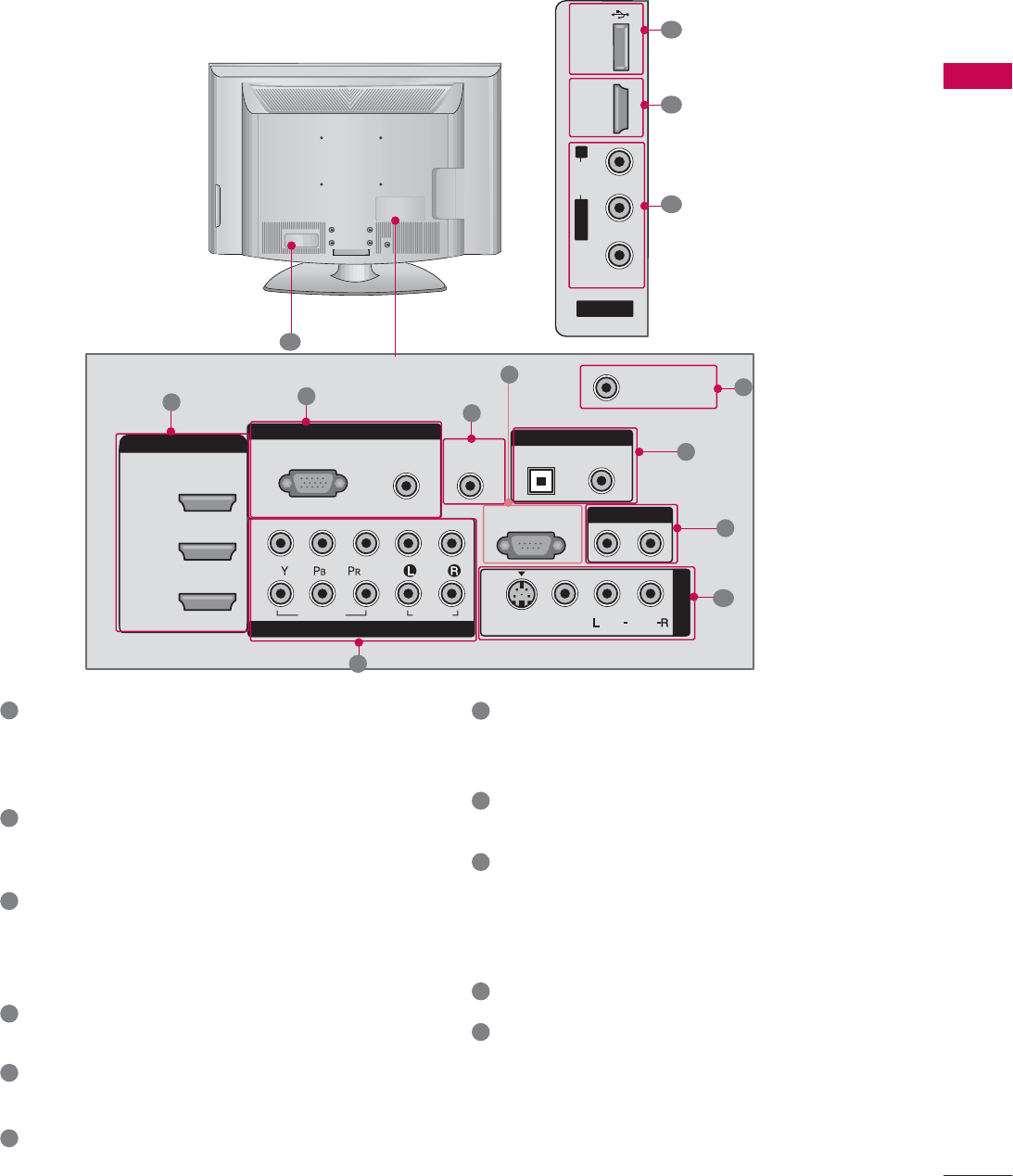
PREPARATION
13
HDMI/DVI IN, HDMI IN
Connect a HDMI signal to HDMI port.
Or DVI (VIDEO) signal to the HDMI port with a
DVI to HDMI cable.
COMPONENT IN
Connect a component video/audio device to these
jacks.
RGB (PC)
Connect the output from a PC.
AUDIO (RGB/DVI)
Connect the audio from a PC.
REMOTE CONTROL PORT
Connect your wired remote control.
RS-232C IN (CONTROL & SERVICE) PORT
Connect to the RS-232C port on a PC.
ANTENNA/CABLE IN
Connect over-the air signals to this jack.
Connect cable signals to this jack.
DIGITAL AUDIO OUT
Connect digital audio to various types of equipment.
Note: In standby mode, these ports do not work.
AUDIO OUT
Connect analog audio to various types of equipment.
AV (Audio/Video) IN
Connect audio/video output from an external
device to these jacks.
S-VIDEO
Connect S-Video out from an S-VIDEO device.
USB INPUT
Power Cord Socket
For operation with AC power.
Caution: Never attempt to operate the TV on DC
power.
1
2
3
4
5
6
7
8
9
10
11
AV IN 2
L/MONO
R
AUDIO
VIDEO
USB
SERVUCE ONLY
HDMI IN 4
RGB IN
COMPONENT IN
AUDIO
(RGB/DVI)
RGB(PC)
REMOTE
CONTROL IN
ANTENNA/
CABLE IN
1
2
RS-232C IN
(CONTROL & SERVICE)
VIDEO
AUDIO
OPTICAL COAXIAL
DIGITAL AUDIO OUT
AUDIO OUT
AV IN 1
HDMI/DVI IN
2
3
1 (DVI)
VIDEO
MONO
( )
AUDIO
S-VIDEO
13
4
6
7
8
2
11
9
9
5
10
1
32/42/47/52LG70
PREPARATION
14
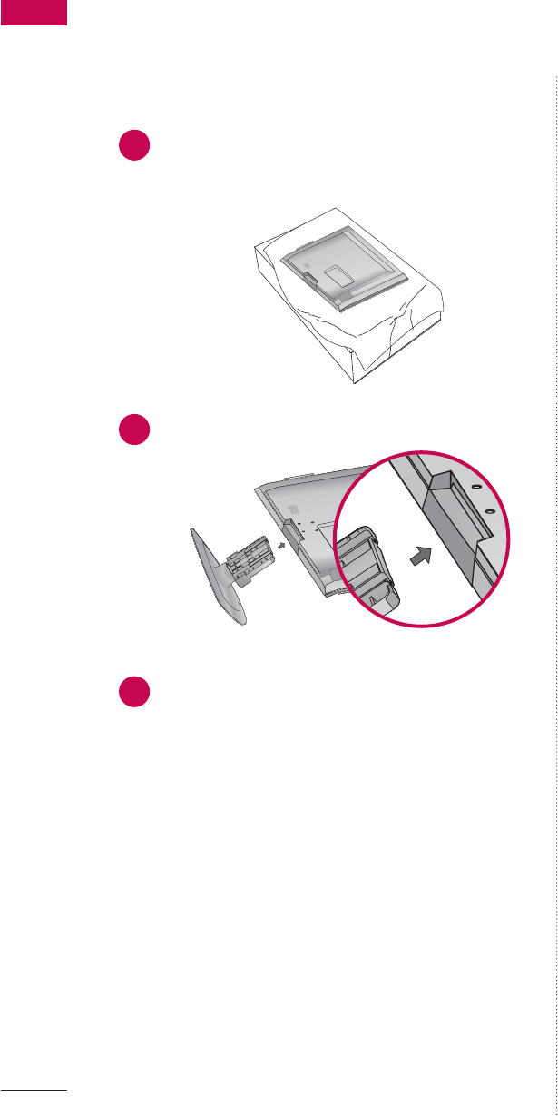
PREPARATION
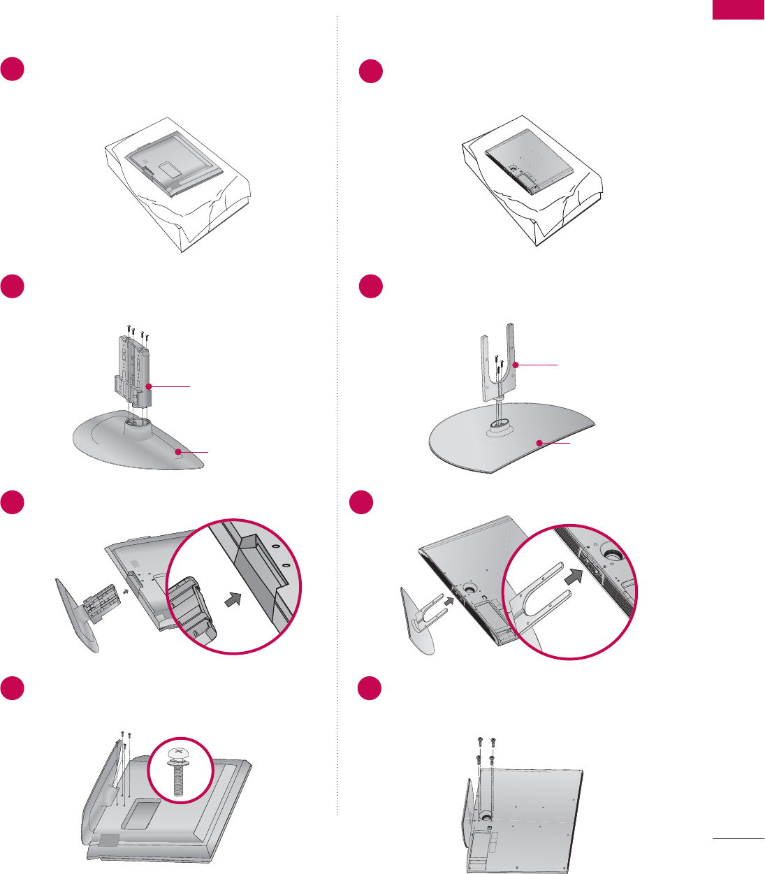
STAND INSTALLATION
■
Image shown may differ from your TV
Carefully place the TV screen side down on a
cushioned surface to protect the screen from
damage.
Assemble the TV as shown.
1
2
Fix the 4 bolts securely using the holes in the
back of the TV
3
42PG10/20
Plasma TV Model
?
PREPARATION
15
Carefully place the TV screen side down on a
cushioned surface to protect the screen from
damage.
Assemble the parts of the STAND B
B
ODY
with COVER B
B
ASE of the TV.
Assemble the TV as shown.
1
2Assemble the parts of the STAND B
B
ODY
with COVER B
B
ASE of the TV.
2
3Assemble the TV as shown.
3
Fix the 4 bolts securely using the holes in the
back of the TV
4Fix the 4 bolts securely using the holes in the
back of the TV
4
Only 26/32/37/42LG30, 37/42LG50 32/37/42/47/52LG60
STAND B
B
ODY
COVER B
B
ASE
STAND B
B
ODY
COVER B
B
ASE
Carefully place the TV screen side down on a
cushioned surface to protect the screen from
damage.
1
LCD TV Model
PREPARATION
16
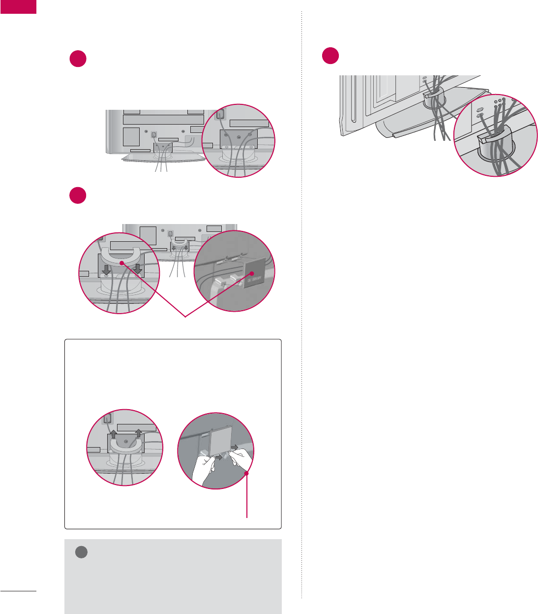
BACK COVER FOR WIRE ARRANGEMENT
PREPARATION
■
Image shown may differ from your TV.
CABLE MANAGEMENT CLIP
How to remove the
CABLE MANAGEMENT CLIP
GHold the CABLE MANAGEMENT CLIP with
both hands and pull it backward.
GDo not hold the CABLE MANAGEMENT
CLIP when moving the TV.
- If the TV is dropped, you may be injured
or the product may be broken.
NOTE
!
Arrange the cables as shown.
1
42/50PG10/20
Plasma TV Model
Connect the cables as necessary.
To connect an additional equipment, see the
EXTERNAL EQUIPMENT SETUP section.
Install the CABLE MANAGEMENT CLIP as
shown and manage the cable.
1
2
50/60PG60F
Separate CABLE MANAGEMENT CLIP
from TV by pressing two latches.
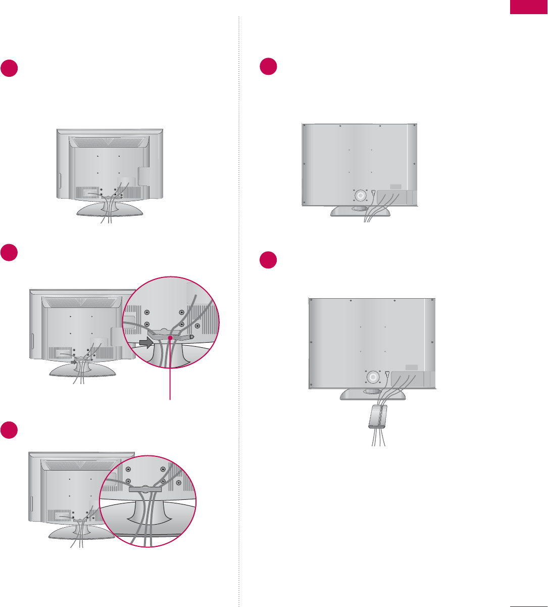
PREPARATION
17
LCD TV Model
Connect the cables as necessary.
To connect an additional equipment, see the
EXTERNAL EQUIPMENT SETUP section.
Install the CABLE MANAGEMENT CLIP as
shown and manage the cable.
CABLE MANAGEMENT CLIP
1
2
Connect the cables as necessary.
To connect an additional equipment, see the
EXTERNAL EQUIPMENT SETUP section of
the manual.
Bundle the cables together using the sup-
plied CABLE MANAGEMENT CLIP.
1
2
Fit the CABLE MANAGEMENT CLIP as shown.
3
32/37/42/47/52LG6026/32/37/42/47/52LG30/50/70
PREPARATION
18
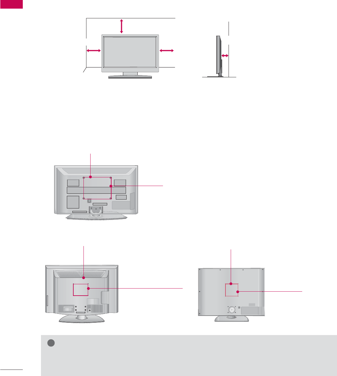
DESKTOP PEDESTAL INSTALLATION
PREPARATION
For proper ventilation, allow a clearance of 4 inches on all four sides from the wall.
■
Image shown may differ from your TV.
4 inches
4 inches
4 inches 4 inches
VESA WALL MOUNTING
This product accepts a VESA-compliant mounting interface pad. (optional)
There 4 threaded holes are available for attaching the bracket.
GScrew length needed depends on the wall mount used. For further information, refer to the VESA
Wall Mounting Instruction Guide.
NOTE
!
Plasma TV Model
LCD TV Model
600 mm
400 mm
200 mm
(Only 52 inches: 800 mm)
200 mm
(Only 52 inches: 400 mm)
600 mm
400 mm
PREPARATION
19
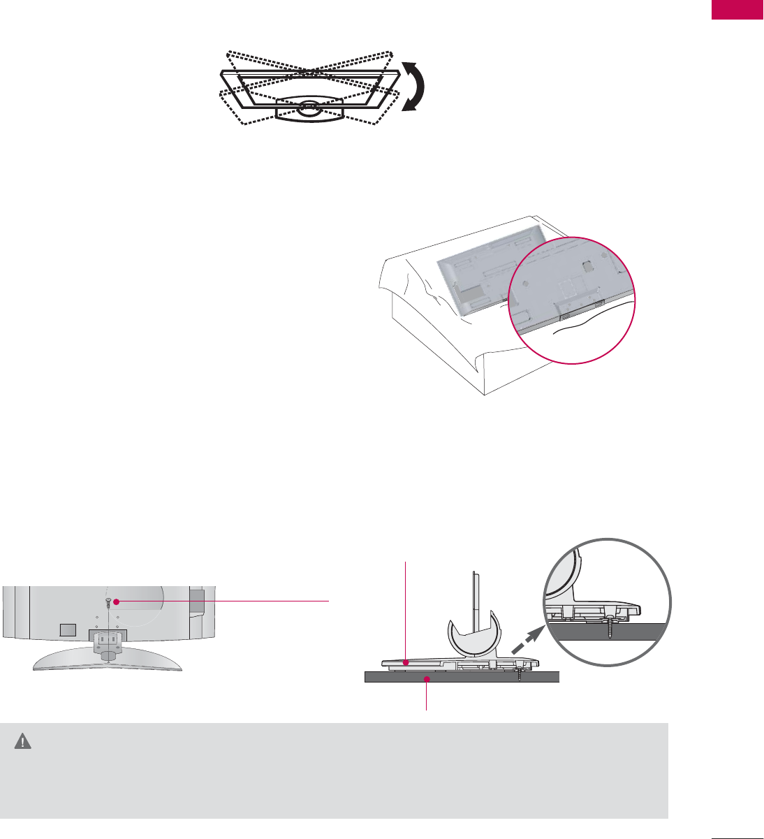
SWIVEL STAND
NOT USING THE DESK-TYPE STAND
After installing the TV, you can adjust the TV set manually to the left or right direction by 20 degrees to suit
your viewing position.
When installing the wall-mounted unit, use the protection
cover for desk-type stand installation.
ATTACHING THE TV TO A DESK
(Only 26/32LG30, 32LG50)
The TV must be attached to a desk so it cannot be pulled in a forward/backward direction, potentially causing
injury or damaging the product.
GThis apparatus must be securely attached to the floor/wall per installation instructions. Tipping, shak-
ing, or rocking the machine may cause injury/death.
WARNING
1-Screw
(provided as parts
of the product)
Desk
Stand
?
PREPARATION
20
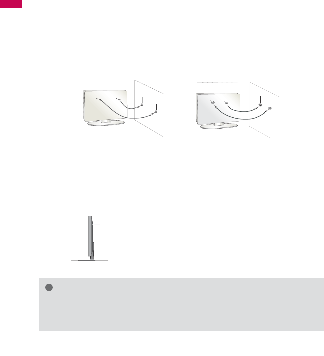
PLEASE SET IT UP CAREFULLY SO THE PRODUCT DOESN’T
FALL OVER.
PREPARATION
We recommend that you set up the TV close to a wall so it cannot fall over if pushed backwards.
Additionally, we recommend that the TV be attached to a wall so it cannot be pulled in a forward direction,
potentially causing injury or damaging the product.
Caution: Please make sure that children don’t climb on or hang from the TV.
■Insert the eye-bolts (or TV brackets and bolts) to tighten the product to the wall as shown in the picture.
*If your product has the bolts in the eye-bolts position before inserting the eye-bolts, loosen the bolts.
* Insert the eye-bolts or TV brackets/bolts and tighten them securely in the upper holes.
Secure the wall brackets with the bolts (not provided as parts of the product, must purchase separately) to
the wall. Match the height of the bracket that is mounted on the wall to the holes in the product.
Ensure the eye-bolts or brackets are tightened securely.
■Use a sturdy rope (not provided as parts of the product, must pur-
chase separately) to tie the product. It is safer to tie the rope so it
becomes horizontal between the wall and the product.
■
You should purchase necessary components to prevent TV from falling off of the stand.
■
Image shown may differ from your TV.
GWhen moving the TV, undo the cords first.
GUse a platform or cabinet strong and large enough to support the size and weight of the TV
GTo use the TV safely make sure that the height of the bracket on the wall and on the TV is the same.
NOTE
!
PREPARATION
21
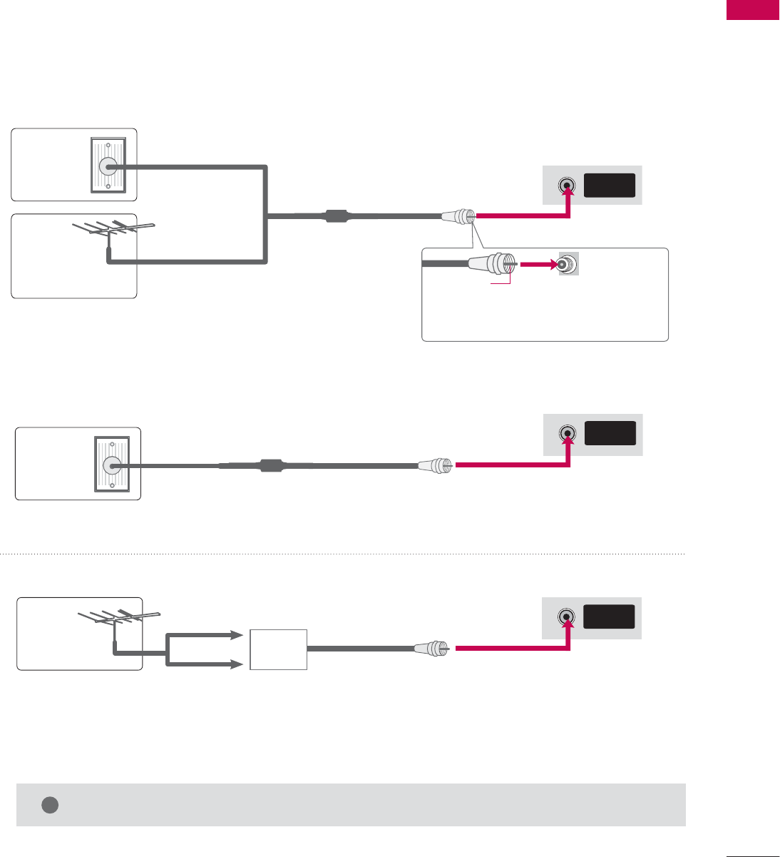
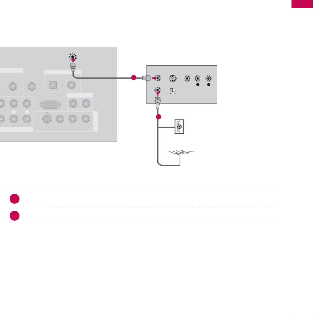
ANTENNA OR CABLE CONNECTION
1. Antenna (Analog or Digital)
Wall Antenna Socket or Outdoor Antenna without a Cable Box
Connections.
For optimum picture quality, adjust antenna direction if needed.
2. Cable
Wall
Antenna
Socket
Outdoor
Antenna
(VHF, UHF)
Cable TV
Wall Jack
Multi-family Dwellings/Apartments
(Connect to wall antenna socket)
RF Coaxial Wire (75 ohm)
RF Coaxial Wire (75 ohm)
Single-family Dwellings /Houses
(Connect to wall jack for outdoor antenna)
Be careful not to bend the bronze wire
when connecting the antenna.
Copper Wire
GThe TV will let you know when the analog, cable, and digital channel scans are complete.
NOTE
!
■To improve the picture quality in a poor signal area, please purchase a signal amplifier and install properly.
■If the antenna needs to be split for two TV’s, install a 2-Way Signal Splitter.
■If the antenna is not installed properly, contact your dealer for assistance.
Antenna
UHF
Signal
Amplifier
VHF
ANTENNA/
CABLE IN
ANTENNA/
CABLE IN
ANTENNA/
CABLE IN
■
Image shown may differ from your TV.
EXTERNAL EQUIPMENT SETUP
22
EXTERNAL EQUIPMENT SETUP
HD RECEIVER SETUP
This TV can receive Digital Over-the-air/Cable signals without an external digital set-top box. However, if you do
receive digital signals from a digital set-top box or other digital external device, refer to the figure as shown below.
When connecting Component cable
1. How to connect
Connect the video outputs (Y, PB, PR)of the digital set
top box to the COMPONENT I
I
N V
V
IDEO 1
1
jacks on
the set. Match the jack colors (Y = green, PB= blue, and
PR= red).
Connect the audio output of the digital set-top box to
the COMPONENT I
I
N A
A
UDIO 1
1
jacks on the set.
2
1
2. How to use
■Turn on the digital set-top box.
(Refer to the owner’s manual for the digital set-top box. operation)
■Select Component 1 input source by using the INPUT
button on the remote control.
■If connected to COMPONENT I
I
N2 input, select
Component 2
2
input source.
■To prevent the equipment damage, never plug in any power cords until you have finished connecting all equipment.
■This part of EXTERNAL EQUIPMENT SETUP mainly use picture for 37/42/47/52LG50 models.
RGB IN
AUDIO
(RGB/DVI)
RGB(PC)
REMOTE
CONTROL IN
RS
(CONTR
D
I/DVI IN
S-V
COMPONENT IN
1
2
VIDEO
LYP
BPRR
AUDIO
Y L RP
B
P
R
12
Y, CB/PB, CR/PR
Horizontal Vertical
Frequency(KHz)Frequency(Hz)
15.73 59.94
15.73 60.00
31.47 59.94
31.50 60.00
44.96 59.94
45.00 60.00
33.72 59.94
33.75 60.00
26.97 23.976
27.00 24.00
33.71 29.97
33.75 30.00
67.432 59.94
67.50 60.00
Resolution
720x480i
720x480p
1280x720p
1920x1080i
1920x1080p
Signal
480i
480p
720p
1080 i
1080 p
Component
Yes
Yes
Yes
Yes
Yes
HDMI
No
Yes
Yes
Yes
Yes
EXTERNAL EQUIPMENT SETUP
23
RGB IN
COMPONENT
A
(RG
RGB(PC)
1
2
VIDEO
YP
BPR
HDMI/DVI IN
2
1 (DVI)
HDMI-DTV OUTPUT
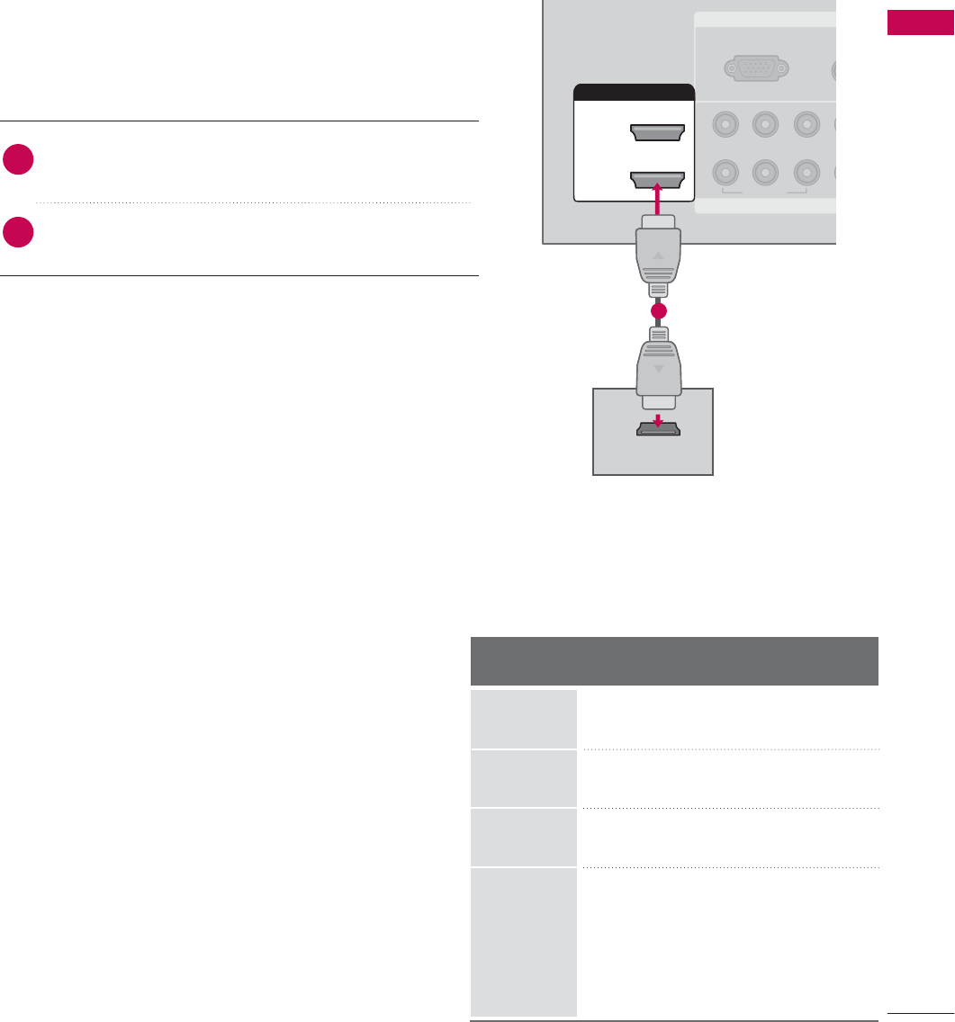
When connecting HDMI cable
Connect the digital set-top box to HDMI/DVI I
I
N1,
2, 3 or 4 jack on the set.
No separated audio connection is necessary.
HDMI supports both audio and video.
1. How to connect
2. How to use
■Turn on the digital set-top box.
(Refer to the owner’s manual for the digital set-top box.)
■Select HDMI1, HDMI2, HDMI3, or HDMI4 input source
with using the INPUT button on the remote control.
2
1
1
HDMI-DTV
Horizontal Vertical
Frequency(KHz)Frequency(Hz)
31.47 59.94
31.50 60.00
44.96 59.94
45.00 60.00
33.72 59.94
33.75 60.00
26.97 23.976
27.00 24.00
33.71 29.97
33.75 30.00
67.432 59.939
67.50 60.00
Resolution
720x480p
1280x720p
1920x1080i
1920x1080p
EXTERNAL EQUIPMENT SETUP
24
EXTERNAL EQUIPMENT SETUP
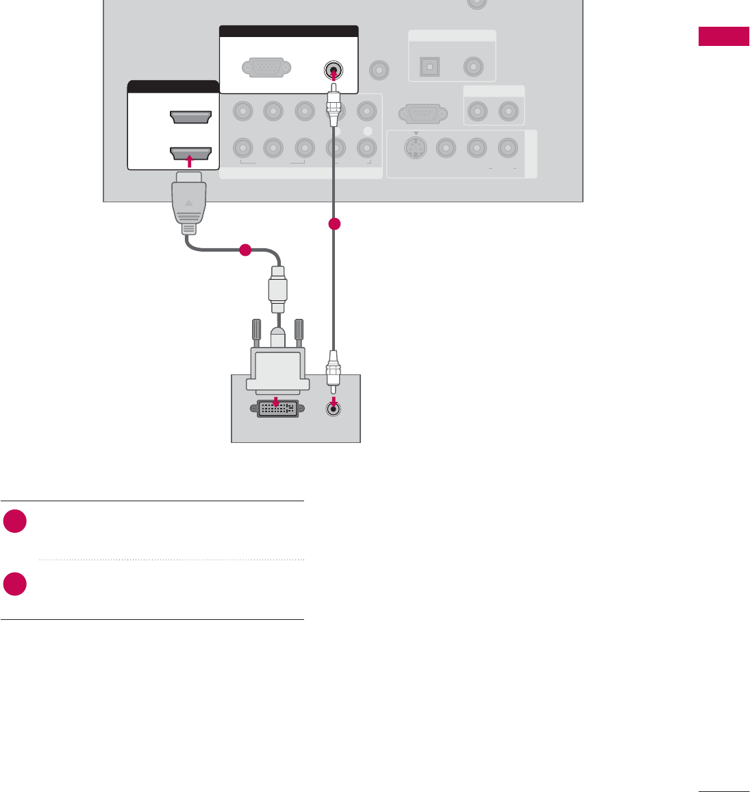
When connecting HDMI to DVI cable
RGB IN
COMPONENT IN
AUDIO
(RGB/DVI)
RGB(PC)
REMOTE
CONTROL IN
ANTENNA/
CABLE IN
1
2
RS-232C IN
(CONTROL & SERVICE)
VIDEO
LYP
B
P
R
R
AUDIO
OPTICAL COAXIAL
DIGITAL AUDIO OUT
AUDIO OUT
AV IN 1
HDMI/DVI IN
2
1 (DVI)
VIDEO L R
(MONO)
AUDIO
S-VIDEO
L R
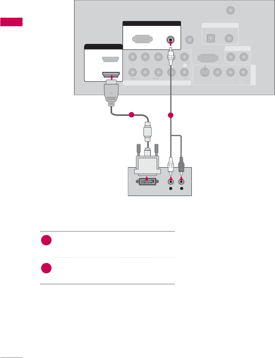
DVI-DTV OUTPUT
Connect the DVI output of the digital set-top box
to the HDMI/DVI I
I
N1(DVI) jack on the set.
Connect the audio output of the digital set-top
box to the AUDIO (RGB/DVI)jack on the set.
1. How to connect
■Turn on the digital set-top box. (Refer to the
owner’s manual for the digital set-top box.)
■Select HDMI1 input source with using the INPUT
button on the remote control.
2. How to use
2
1
12
EXTERNAL EQUIPMENT SETUP
25
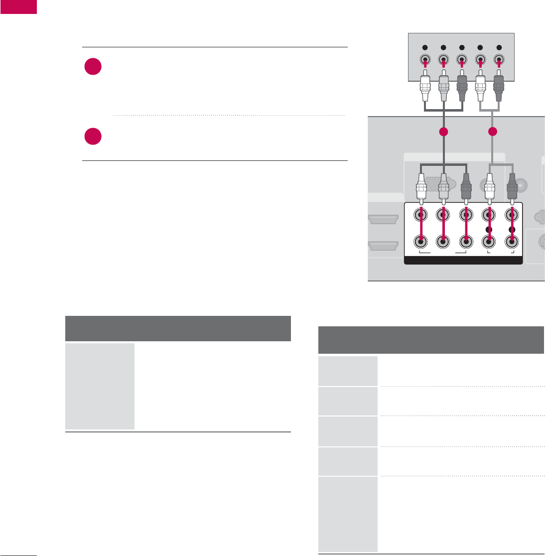
DVD SETUP
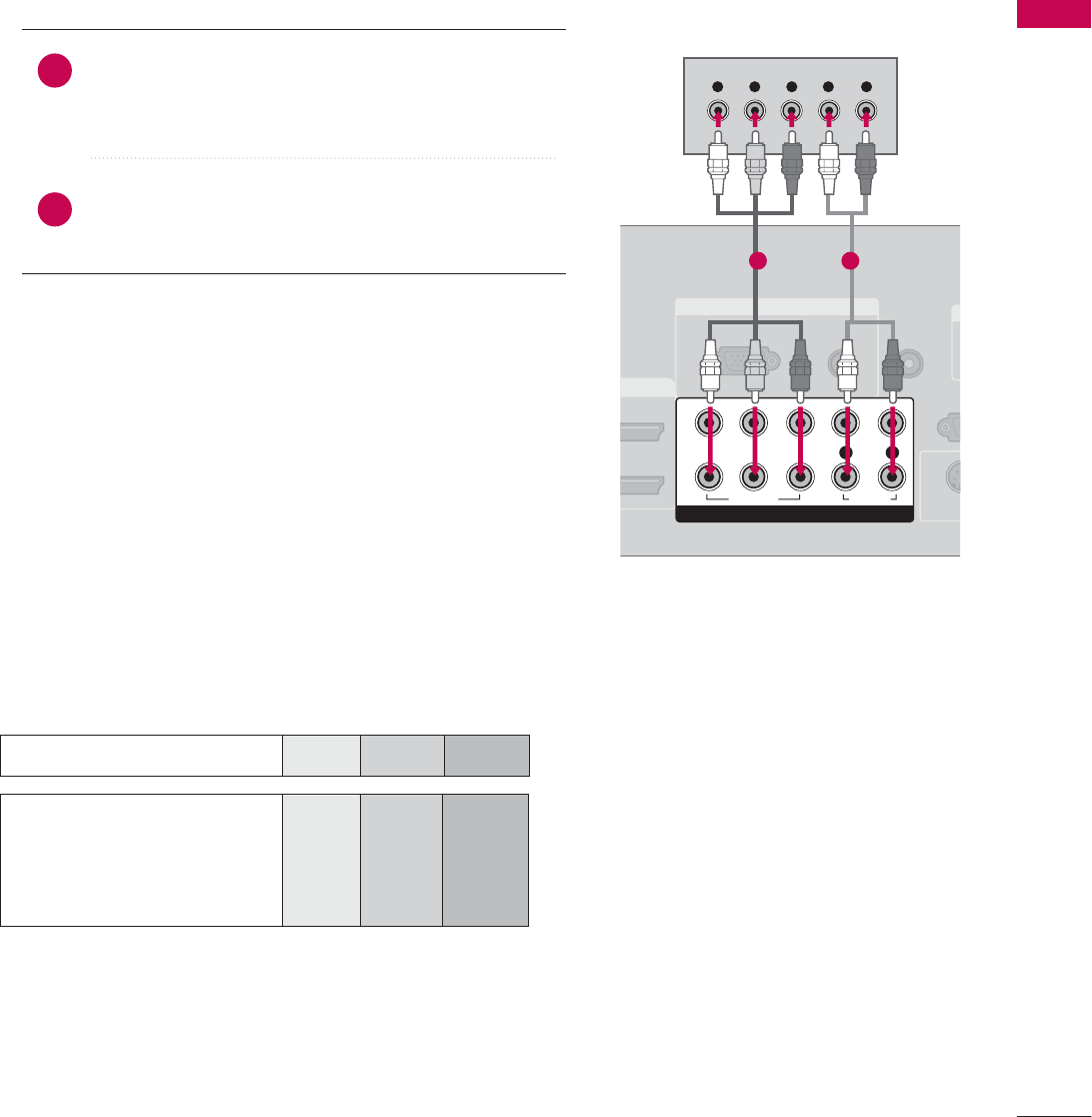
When connecting Component cable
Component Input ports
To get better picture quality, connect a DVD player to the component input ports as shown below.
Component ports on the TV
YP
BPR
Video output ports
on DVD player
Y
Y
Y
Y
PB
B-Y
Cb
Pb
PR
R-Y
Cr
Pr
Connect the video outputs (Y, PB, PR)of the DVD to the
COMPONENT I
I
N V
V
IDEO1 jacks on the set.
Match the jack colors (Y = green, PB= blue, and PR= red).
Connect the audio outputs of the DVD to the
COMPONENT I
I
N A
A
UDIO1 jacks on the set.
1. How to connect
2. How to use
■Turn on the DVD player, insert a DVD.
■Select Component 1 input source by using the INPUT
button on the remote control.
■If connected to COMPONENT I
I
N 2
2
input, select
Component 2
2
input source.
■Refer to the DVD player's manual for operating instructions.
2
1
RGB IN
AUDIO
(RGB/DVI)
RGB(PC)
REMOTE
CONTROL IN
RS-
(CONTRO
O
D
VI IN
S-V
COMPONENT IN
1
2
VIDEO
LYP
BPRR
AUDIO
Y L RP
B
P
R
1 2
EXTERNAL EQUIPMENT SETUP
26
EXTERNAL EQUIPMENT SETUP
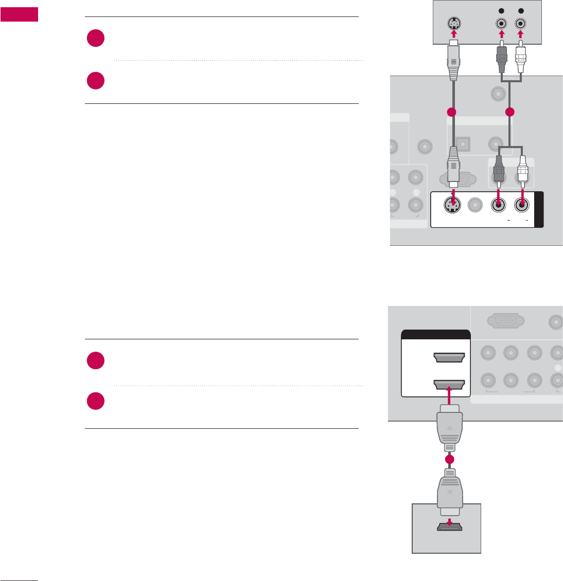
When connecting with an S-Video cable
Connect the S-VIDEO output of the DVD to the
S-VIDEO input on the set.
Connect the audio outputs of the DVD to the AUDIO
input jacks on the set.
1. How to connect
2. How to use
■Turn on the DVD player, insert a DVD.
■Select AV1 input source by using the INPUT button on the
remote control.
■Refer to the DVD player's manual for operating instructions.
When connecting HDMI cable
Connect the HDMI output of the DVD to the
HDMI/DVI I
I
N1, 2, 3 or 4jack on the set.
No separated audio connection is necessary.
HDMI supports both audio and video.
1. How to connect
2. How to use
■Select HDMI1, HDMI2, HDMI3, or HDMI4 input source
by using the INPUT button on the remote control.
■Refer to the DVD player's manual for operating instructions.
2
1
2
1
N
UDIO
B/DVI)
REMOTE
CONTROL IN
ANTENNA/
CABLE IN
RS-232C IN
(CONTROL & SERVICE)
LR
AUDIO
OPTICAL COAXIAL
DIGITAL AUDIO OUT
AUDIO OUT
AV IN 1
VIDEO LR
(MONO)
AUDIO
S-VIDEO
L R
S-VIDEO
AUDIO
12
COMPONENT IN
UO
(RGB/D
RGB(PC)
1
2
VIDEO
LYP
BPR
A
HDMI/DVI IN
2
1 (DVI)
HDMI-DVD OUTPUT
1
EXTERNAL EQUIPMENT SETUP
27
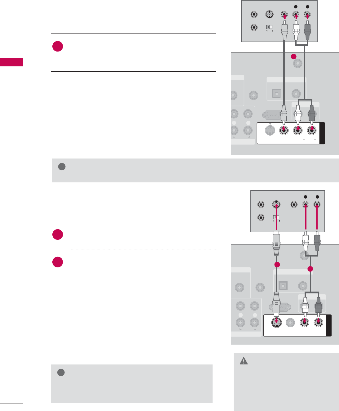
VCR SETUP
When connecting with an antenna
■To avoid picture noise (interference), leave an adequate distance between the VCR and TV.
■Use the ISM feature in the Option menu to avoid having a fixed image remain on the screen for a long period
of time
(Only
Plasma TV model
)
. If the 4:3 picture format is used; the fixed images on the sides of the screen
may remain visible on the screen. This phenomenon is common to all manufactures and in consequence the
manufactures warranty does not cover the product bearing this phenomenon.
Connect the RF antenna out socket of the VCR to the ANTENNA/CABLE I
I
Nsocket on the set.
Connect the antenna cable to the RF antenna in socket of the VCR.
1. How to connect
■Set VCR output switch to 3 or 4 and then tune TV to the same channel number.
■Insert a video tape into the VCR and press PLAY on the VCR. (Refer to the VCR owner’s manual.)
2. How to use
2
1
NENT IN
AUDIO
(RGB/DVI)
REMOTE
CONTROL IN
ANTENNA/
CABLE IN
RS-232C IN
(CONTROL & SERVICE)
LPRR
AUDIO
OPTICAL COAXIAL
DIGITAL AUDIO OUT
AUDIO OUT
AV IN 1
VIDEO L R
(MONO)
AUDIO
S-VIDEO
L R
S-VIDEO VIDEO
OUTPUT
SWITCH
ANT IN
ANT OUT
Wall Jack
Antenna
1
2
EXTERNAL EQUIPMENT SETUP
28
EXTERNAL EQUIPMENT SETUP
GDo not connect to both Video
and S-Video at the same time. In
the event that you connect both
Video and the S-Video cables,
only the S-Video will work.
CAUTION
When connecting with a RCA cable
GThe picture quality is improved: compared to normal
composite (RCA cable) input.
NOTE
!
Connect the AUDIO/VIDEO jacks between TV and
VCR. Match the jack colors (Video = yellow, Audio Left
= white, and Audio Right = red)
1. How to connect
2. How to use
■Insert a video tape into the VCR and press PLAY on the
VCR. (Refer to the VCR owner’s manual.)
■Select AV1 input source by using the INPUT button on
the remote control.
■If connected to AV I
I
N2, select AV2 input source.
When connecting with an S-Video cable
Connect the S-VIDEO output of the VCR to the
S-VIDEO input on the set.
Connect the audio outputs of the VCR to the AUDIO
input jacks on the set.
1. How to connect
2. How to use
■Insert a video tape into the VCR and press PLAY on the VCR.
(Refer to the VCR owner’s manual.)
■Select AV1 input source by using the INPUT button on the
remote control.
1
2
1
GIf you have a mono VCR, connect the audio cable from the VCR to the AUDIO
L/MONO jack of the set.
NOTE
!
N
UDIO
B/DVI)
REMOTE
CONTROL IN
ANTENNA/
CABLE IN
RS-232C IN
(CONTROL & SERVICE)
LR
AUDIO
OPTICAL COAXIAL
DIGITAL AUDIO OUT
AUDIO OUT
AV IN 1
VIDEO L R
(MONO)
AUDIO
S-VIDEO
L R
S-VIDEO VIDEO
OUTPUT
SWITCH
ANT IN
ANT OUT
1
NT IN
AUDIO
(RGB/DVI)
REMOTE
CONTROL IN
ANTENNA/
CABLE IN
RS-232C IN
(CONTROL & SERVICE)
LR
AUDIO
OPTICAL COAXIAL
DIGITAL AUDIO OUT
AUDIO OUT
AV IN 1
VIDEO LR
(MONO)
AUDIO
S-VIDEO
L R
S-VIDEO VIDEO
OUTPUT
SWITCH
ANT IN
ANT OUT
1
2
EXTERNAL EQUIPMENT SETUP
29
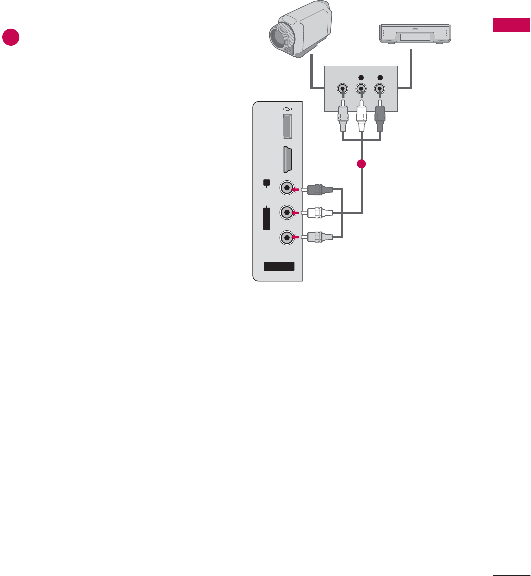
OTHER A/V SOURCE SETUP
AV IN 2
L/MONO
R
AUDIO
VIDEO
USB
SERVUCE ONLY
HDMI IN 3
L R
VIDEO
Camcorder
Video Game Set
Connect the AUDIO/VIDEO jacks
between TV and external equipment.
Match the jack colors
.
(Video = yellow, Audio Left = white, and
Audio Right = red)
1. How to connect
2. How to use
■Select AV2 input source by using the INPUT
button on the remote control.
■If connected to AV I
I
N1 input, select AV1
input source.
■Operate the corresponding external equipment.
1
1
EXTERNAL EQUIPMENT SETUP
30
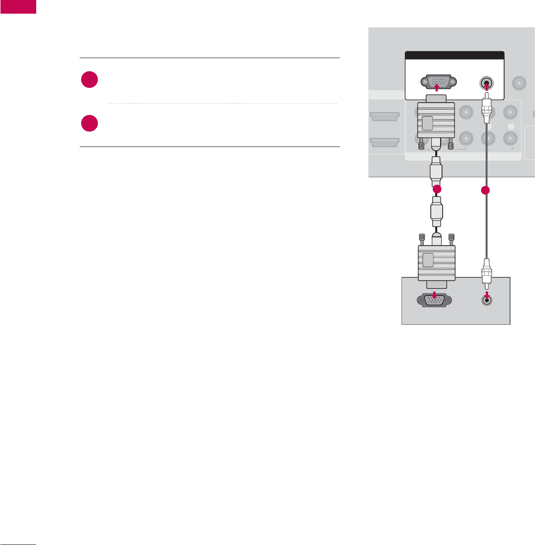
PC SETUP
EXTERNAL EQUIPMENT SETUP
This TV provides Plug and Play capability, meaning that the PC adjusts automatically to the TV's settings.
When connecting D-sub 15 pin cable
Connect the RGB output of the PC to the RGB (P C)
jack on the set.
Connect the PC audio output to the AUDIO
(RGB/DVI)jack on the set.
1. How to connect
2. How to use
■Turn on the PC and the TV.
■Select RGB-PC input source by using the INPUT button
on the remote control.
2
1
AUDIO
COMPONENT IN
REMOTE
CONTROL IN
1
2
(CO
VIDEO
LYP
BPRR
AUDIO
MI/DVI IN
RGB IN
AUDIO
(RGB/DVI)
RGB(PC)
RGB OUTPUT
12
EXTERNAL EQUIPMENT SETUP
31
When connecting HDMI to DVI cable
COMPONENT IN
REMOTE
CONTROL IN
CABLE IN
1
2
RS-232C IN
(CONTROL & SERVICE)
VIDEO
LYP
BPRR
AUDIO
OPTICAL COAXIAL
DIGITAL AUDIO OUT
AUDIO OUT
AV IN 1
HDMI/DVI IN
2
1 (DVI)
VIDEO L R
(MONO)
AUDIO
S-VIDEO
RGB IN
AUDIO
(RGB/DVI)
RGB(PC)
DVI-PC OUTPUT AUDIO
1
2
Connect the DVI output of the PC to the
HDMI/DVI I
I
N1(DVI) jack on the set.
Connect the PC audio output to the AUDIO
(RGB/DVI) jack on the set.
1. How to connect
■Turn on the PC and the TV.
■Select HDMI1 input source with using the
INPUT button on the remote control.
2. How to use
2
1
EXTERNAL EQUIPMENT SETUP
32
EXTERNAL EQUIPMENT SETUP
GFor LCD TV: To get the the best picture quality,
adjust the PC graphics card to 1366x768.
GFor Plasma TV: To get the the best picture quality,
adjust the PC graphics card to 1360x768.
GDepending on the graphics card, DOS mode may
not work if a HDMI to DVI Cable is in use.
GCheck the image on your TV. There may be noise
associated with the resolution, vertical pattern,
contrast or brightness in PC mode. If noise is
present, change the PC output to another resolu-
tion, change the refresh rate to another rate or
adjust the brightness and contrast on the
PICTURE menu until the picture is clear. If the
refresh rate of the PC graphic card can not be
changed, change the PC graphic card or consult
the manufacturer of the PC graphic card.
GAvoid keeping a fixed image on the screen for a
long period of time. The fixed image may become
permanently imprinted on the screen.
GThe synchronization input form for Horizontal and
Vertical frequencies is separate.
NOTES
!
Horizontal Vertical
Frequency(KHz)Frequency(Hz)
31.469 70.08
31.469 70.08
31.469 59.94
37.879 60.31
48.363 60.00
47.776 59.87
47.720 59.799
47.130 59.65
Resolution
720x400
1360x768
640x350
640x480
800x600
1024x768
1280x768
1366x768
Supported Display Specifications
For 26/32/37/42LG30, 42/50PG10, 42/50PG20
RGB-PC, HDMI-PC
* Only RGB-PC mode
* Only LCD TV
EXTERNAL EQUIPMENT SETUP
33
Supported Display Specifications
GDepending on graphic card and signal status, there can be some shaking to find best picture in a little time.
NOTE
!
RGB-PC, HDMI-PC
Resolution
720x400
1360x768
640x350
640x480
800x600
1024x768
1280x1024
1600x1200
1920x1080
1280x768
* RGB-PC mode only
Horizontal Vertical
Frequency(KHz)Frequency(Hz)
31.468 70.09
31.469 70.08
31.469 59.94
37.500 75.00
37.861 72.80
35.156 56.25
37.879 60.31
46.875 75.00
48.077 72.18
48.363 60.00
56.476 70.06
60.023 75.02
47.776 59.87
60.289 74.893
63.981 60.02
79.976 75.025
47.712 60.015
75.00 60.00
66.587 59.934
For 37/42/47/52LG50, 32/37/42/47/52LG60
32/42/47/52LG70, 50/60PG60F
EXTERNAL EQUIPMENT SETUP
34
EXTERNAL EQUIPMENT SETUP
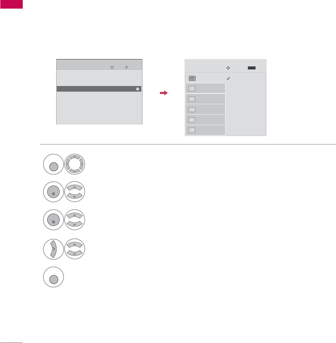
Screen Setup for PC mode
Selecting Resolution
When you change the resolution, select the proper resolution in present input to see the best picture appearance.
XGA (1024, 1280, 1360) isn’t distinguished because of having the same H/V Sync Time. This function is you
to select the Default Sync Time.
This feature operates only in RGB-PC mode.
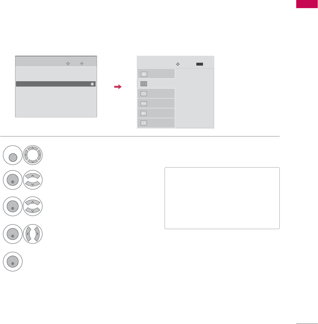
Select PICTURE.
Select SCREEN.
Select Resolution.
Select the desired resolution.
1024 x 768
1280 x 768
1360 x 768
Auto Config.
Resolution
G
Position
Size
Phase
Reset
SCREEN
Move
Prev.
MENU
1
MENU
3
4
2
ENTER
ENTER
Enter
Move
PICTURE
E
• Advanced Control
• Picture Reset
Screen
TruMotion Demo
Return to the previous menu.
5
MENU
EXTERNAL EQUIPMENT SETUP
35
Auto Configure
Automatically adjusts picture position and minimizes image instability. After adjustment, if the image is still
not correct, your TV is functioning properly but needs further adjustment.
Auto c
c
onfigure
This function is for automatic adjustment of the screen position, clock, and phase The displayed image will
be unstable for a few seconds while the auto configuration is in progress.
Select SCREEN.
Select Auto C
C
onfig..
Auto Config.
G
Resolution
Position
Size
Phase
Reset
SCREEN
Move
Prev.
MENU
Auto config.
3
2
ENTER
ENTER
Select Yes.
4
ENTER
Start Auto Configuration.
5
ENTER
Enter
Move
PICTURE
E
• Advanced Control
• Picture Reset
Screen
TruMotion Demo
Select PICTURE.
1
MENU
• If the position of the image is still not
correct, try Auto adjustment again.
• If picture needs to be adjusted again
after Auto adjustment in RGB-PC, you
can adjust the Position, Size or
Phase.
PREPARATION
36
PREPARATION
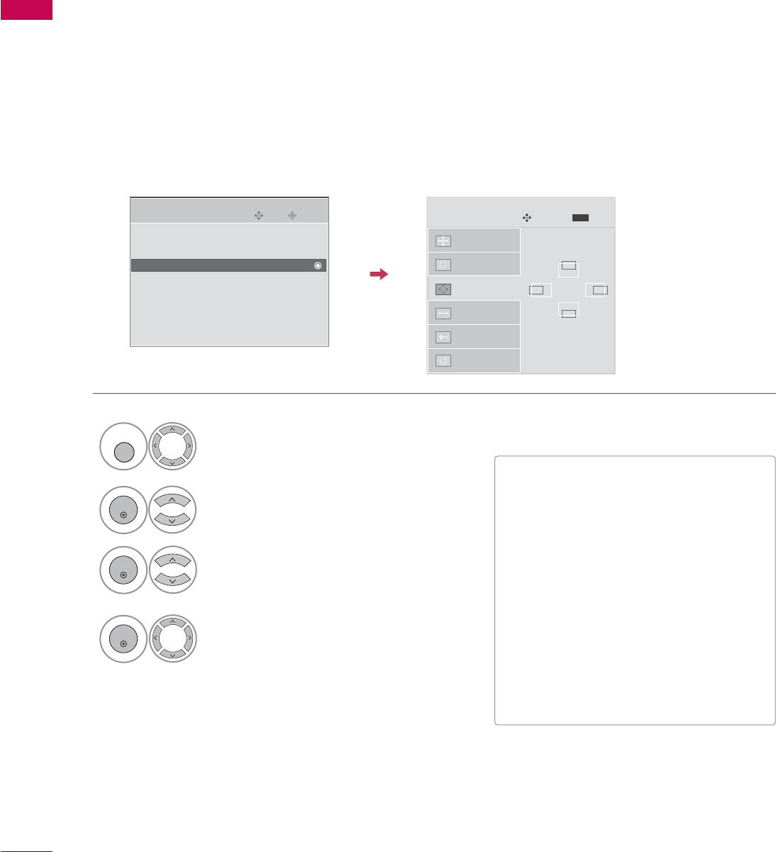
Adjustment for screen Position, Size, and Phase
If the picture is not clear after auto adjustment and especially if characters are still trembling, adjust the picture
phase manually.
This feature operates only in RGB-PC mode.
Select Position, Size, or Phase.
Make appropriate adjustments.
Auto Config.
Resolution
Position
G
Size
Phase
Reset
GF
D
E
SCREEN
Move
Prev.
MENU
3
ENTER
4
ENTER
• Position: This function is to adjust pic-
ture to left/right and up/down as you
prefer.
• Size: This function is to minimize any
vertical bars or stripes visible on the
screen background. And the horizontal
screen size will also change. The Size
adjustment range is -30 ~+30.
• Phase: This function allows you to
remove any horizontal noise and clear or
sharpen the image of characters. The
Phase adjustment range is -16 ~+16.
Select PICTURE.
Select SCREEN.
1
MENU
2
ENTER
Enter
Move
PICTURE
E
• Advanced Control
• Picture Reset
Screen
TruMotion Demo
PREPARATION
37
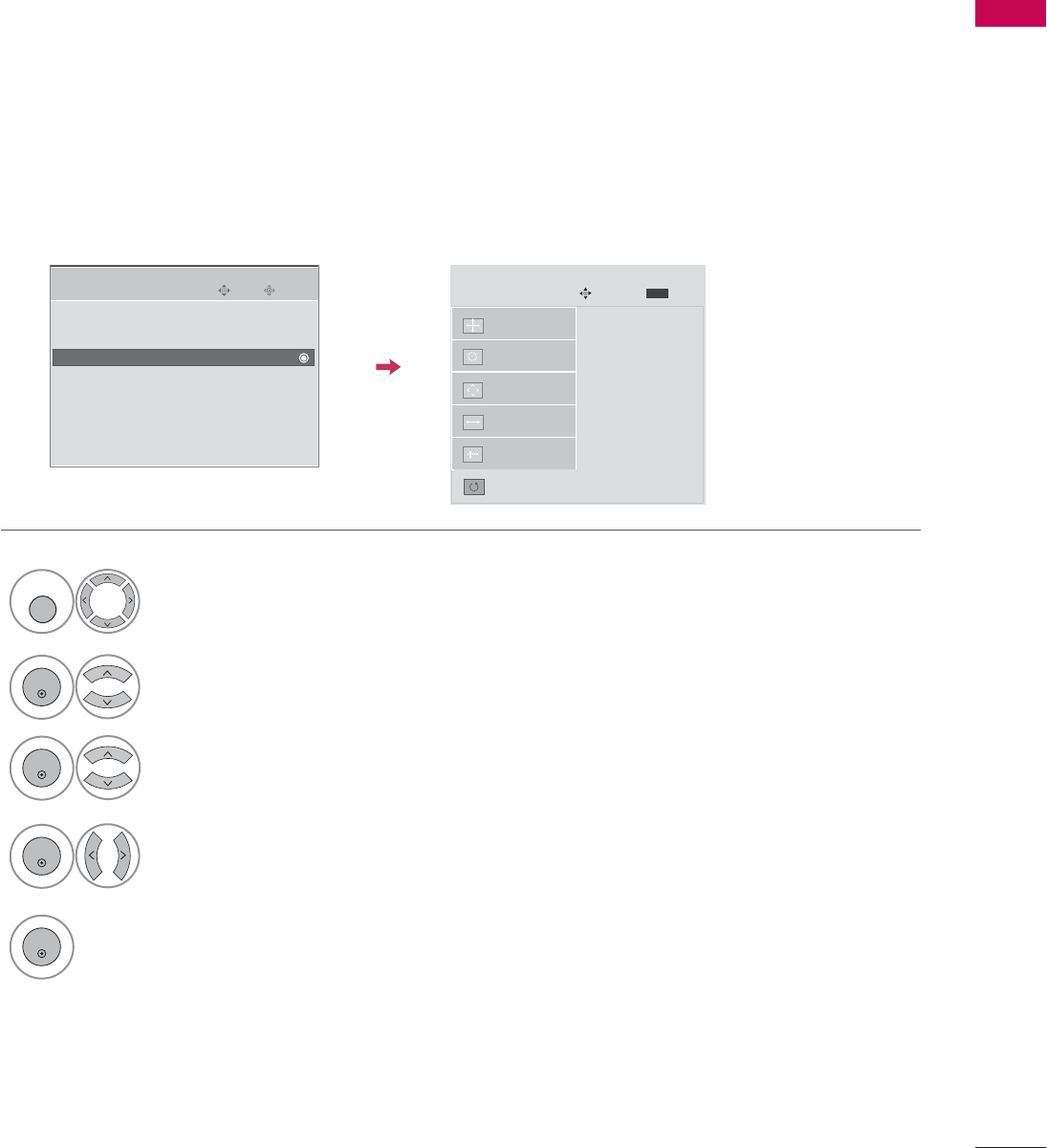
Screen Reset (Reset to original factory values)
Returns to the default settings Resolution, Auto Config., Position, Size and Phase at the factory.
Auto Config.
Position
Resolution
Size
Phase
Reset
G
SCREEN
Move
Prev.
MENU
Initialize Settings.
Select Reset.
3
ENTER
Select PICTURE.
Select SCREEN.
1
MENU
2
ENTER
Enter
Move
PICTURE
E
• Advanced Control
• Picture Reset
Screen
TruMotion Demo
Select Yes.
4
ENTER
5
ENTER
EXTERNAL EQUIPMENT SETUP
38
USB IN SETUP
EXTERNAL EQUIPMENT SETUP
AV IN 2
L/MONO
R
AUDIO
VIDEO
USB
SERVUCE ONLY
HDMI IN 3
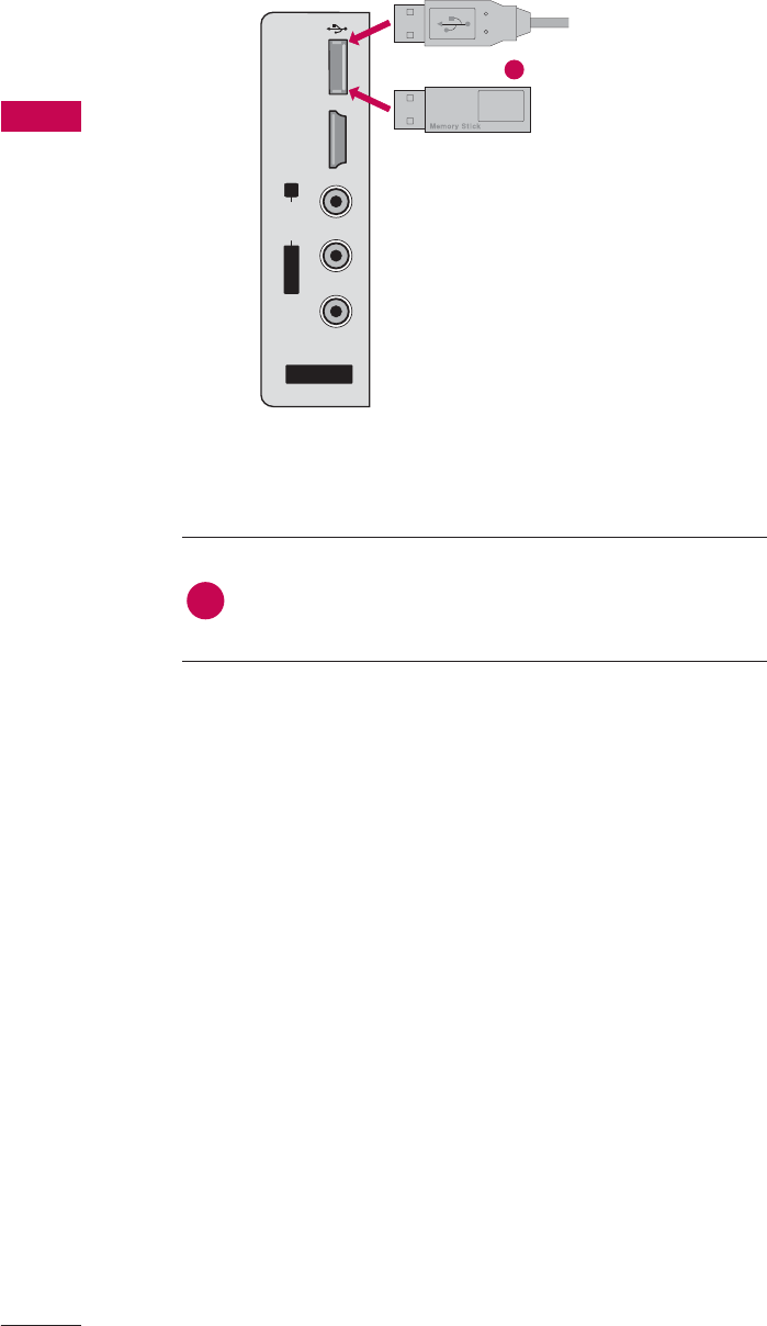
Connect the USB device to the USB S
S
ERVICE O
O
NLY
jack on the side of TV.
1. How to connect
1
2. How to use
■After connecting the USB jack, you use the USB function.
(Gp.56)
1
or
EXTERNAL EQUIPMENT SETUP
39
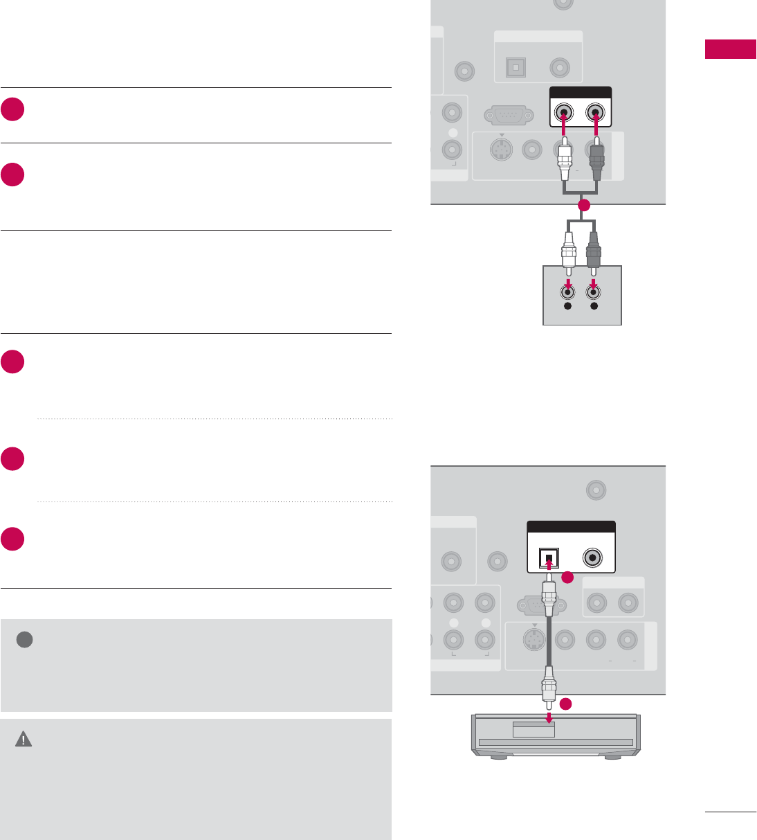
AUDIO OUT SETUP
Send the TV’s audio to external audio equipment via the Audio Output port.
O
VI)
REMOTE
CONTROL IN
CABLE IN
RS-232C IN
(CONTROL & SERVICE)
R
UDIO
OPTICAL COAXIAL
DIGITAL AUDIO OUT
AUDIO OUT
AV IN 1
VIDEO L R
(MONO)
AUDIO
S-VIDEO
L R
AUDIO
1
NT IN
AUDIO
(RGB/DVI)
REMOTE
CONTROL IN
ANTENNA/
CABLE IN
RS-232C IN
(CONTROL & SERVICE)
LR
AUDIO
OPTICAL COAXIAL
DIGITAL AUDIO OUT
AUDIO OUT
AV IN 1
VIDEO L R
(MONO)
AUDIO
S-VIDEO
1
2
GWhen connecting with external audio equipments, such as ampli-
fiers or speakers, please turn the TV speakers off. (G p.85)
NOTE
!
GDo not look into the optical output port. Looking at the
laser beam may damage your vision.
GBlock the SPDIF out (optical/coaxial) about the contents
with ACP(Audio Copy Protection) function.
CAUTION
Connect one end of the optical or coaxial cable to the TV’s
OPTICAL or COAXIAL (Except **LG30) port of DIGITAL
AUDIO O
O
UT.
Connect the other end of the optical or coaxial cable to the
digital audio input on the audio equipment.
Set the “TV Speaker option - Off” in the AUDIO menu. (G
p.85). See the external audio equipment instruction manual
for operation.
1. How to connect
2
3
1
Connect audio outputs to the TV’s AUDIO O
O
UT jacks.
Set the “TV Speaker option - Off” in the AUDIO menu.
(Gp.85). See the external audio equipment instruction
manual for operation.
1. How to connect
2
1
Analog
Digital
WATCHING TV / CHANNEL CONTROL
40
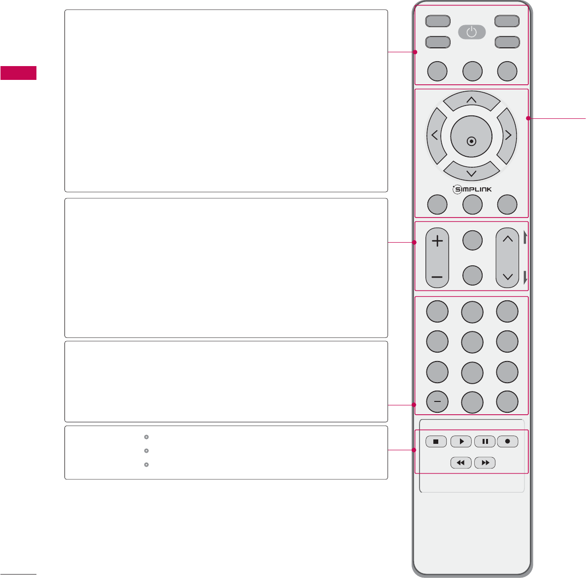
REMOTE CONTROL FUNCTIONS
WATCHING TV / CHANNEL CONTROL
When using the remote control, aim it at the remote control sensor on the TV.
INPUT
FAV
MUTE
TV
STB
POWER
Q. MENU MENU
AV MODERETURN
ENTER
VOL CH
123
456
78
0
9
FLASHBK
P
A
G
E
DVD
VCR
TV/STB/DVD/VCR
POWER
Q.MENU
MENU
INPUT
VOLUME UP
/DOWN
FAV
MUTE
CHANNEL
UP/DOWN
PAGE
UP/DOWN
— (DASH)
BACK
Select the remote operating mode: TV, STB, DVD, or VCR.
* If the mode of another product is selected, a button on
the remote control which is not used for the selected
product can control the TV.
Turns your TV or any other programmed equipment on or
off, depending on the mode.
Select the desired quick menu source. Gp.43
Displays the main menu.
External input modes rotate in regular sequence
Increase/decrease the sound level.
Scroll through the programmed Favorite channels. Gp.43
Switch the sound on or off. Gp.42
Select available channels.
Move from one full set of screen information to the next one.
Used to enter a program number for multiple
program channels such as 2-1, 2-2, etc.
Tune to the last channel viewed.
Control video cassette recorders or DVD players.
Control USB menu (PHOTO LIST and MUSIC LIST.)
Control the SIMPLINK compatible devices.
NUMBER button
VCR/DVD
buttons
WATCHING TV / CHANNEL CONTROL
41
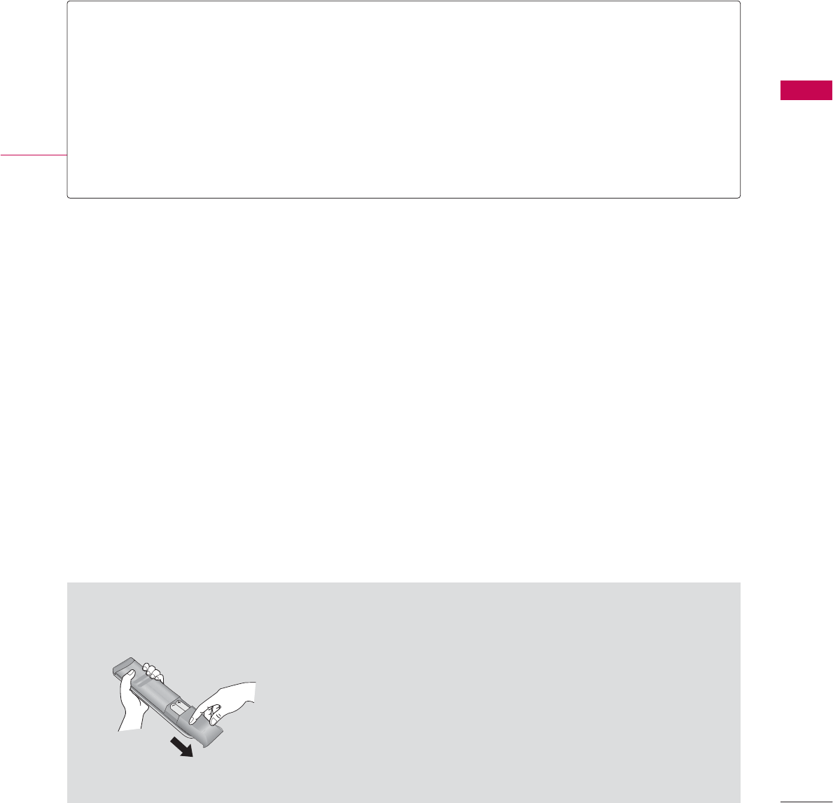
Installing Batteries
■
Open the battery compartment cover on the back side and install
the batteries matching correct polarity (+with +,-with -).
■
Install two 1.5V AAA batteries. Don’t mix old or used batteries with
new ones.
■
Close cover.
THUMBSTICK
(Up/Down/Left
Right/ENTER)
RETURN
SIMPLINK
AV MODE
Navigate the on-screen menus and adjust the system settings to your preference.
Clear all on-screen displays and return to TV viewing from any menu.
See a list of AV devices connected to TV.
When you toggle this button, the SimpLink menu appears at the screen. Gp.54-55
It helps you select and set images and sounds when connecting AV devices. Gp.53
WATCHING TV / CHANNEL CONTROL
42
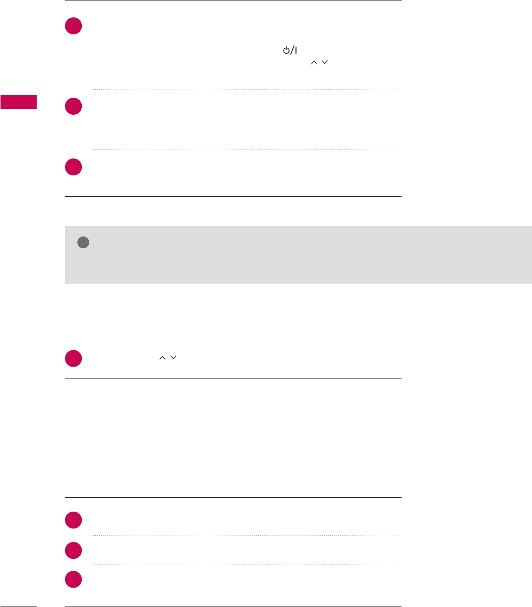
TURNING ON TV
WATCHING TV / CHANNEL CONTROL
NOTE
!
GIf you intend to be away on vacation, disconnect the power plug from the wall power outlet.
First, connect power cord correctly.
At this moment, the TV switches to standby mode.
■In standby mode to turn TV on, press the , INPUT,CH (
(
Dor E)
button on the TV or press the POWER, INPUT, CH( ), Number (
(
0~9)
button on the remote control.
Select the viewing source by using the INPUTbutton on the remote control.
■This TV is programmed to remember which power state it was last set to,
even if the power cord is out.
When finished using the TV, press the POWER button on the remote control.
The TV reverts to standby mode.
1
2
3
Press the CH ( ) or NUMBER buttons to select a channel number.
1
VOLUME ADJUSTMENT
CHANNEL SELECTION
Press the VOL (+ or -) button to adjust the volume.
If you want to switch the sound off, press the MUTE button.
You can cancel the Mute function by pressing the MUTE or VOL (+ or -)
button.
Adjust the volume to suit your personal preference.
1
2
3
WATCHING TV / CHANNEL CONTROL
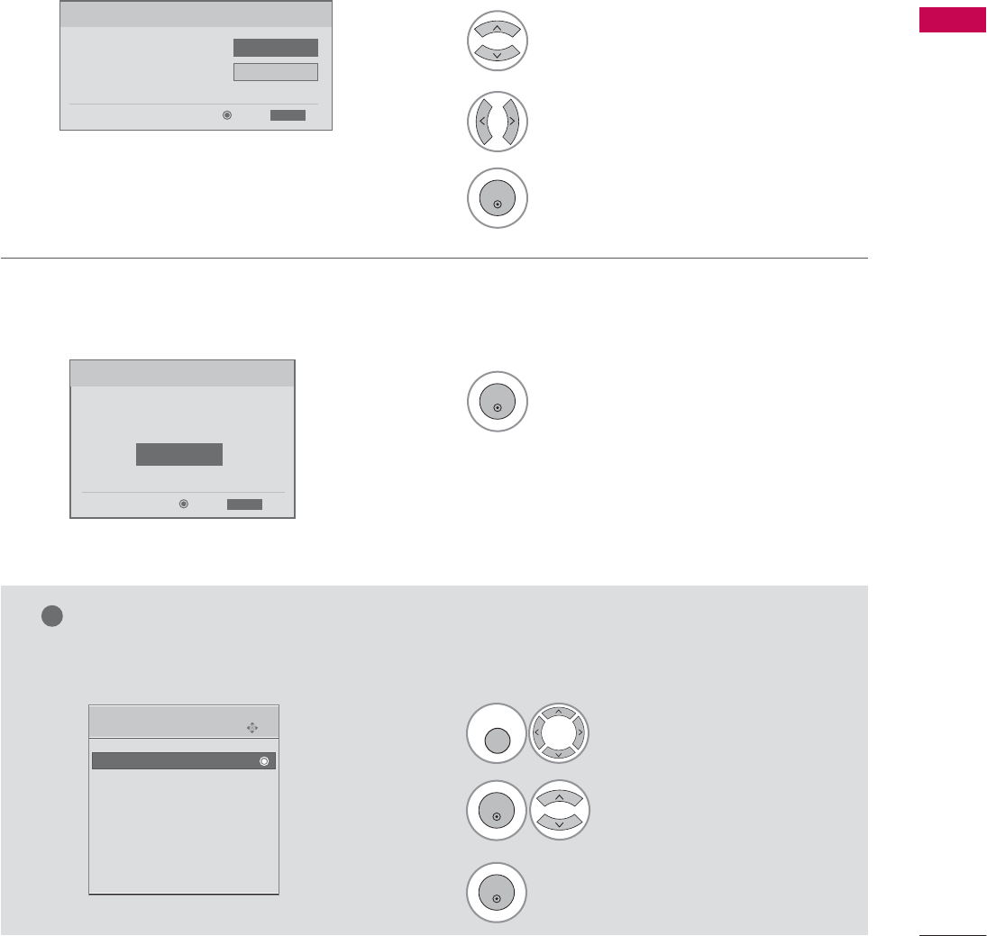
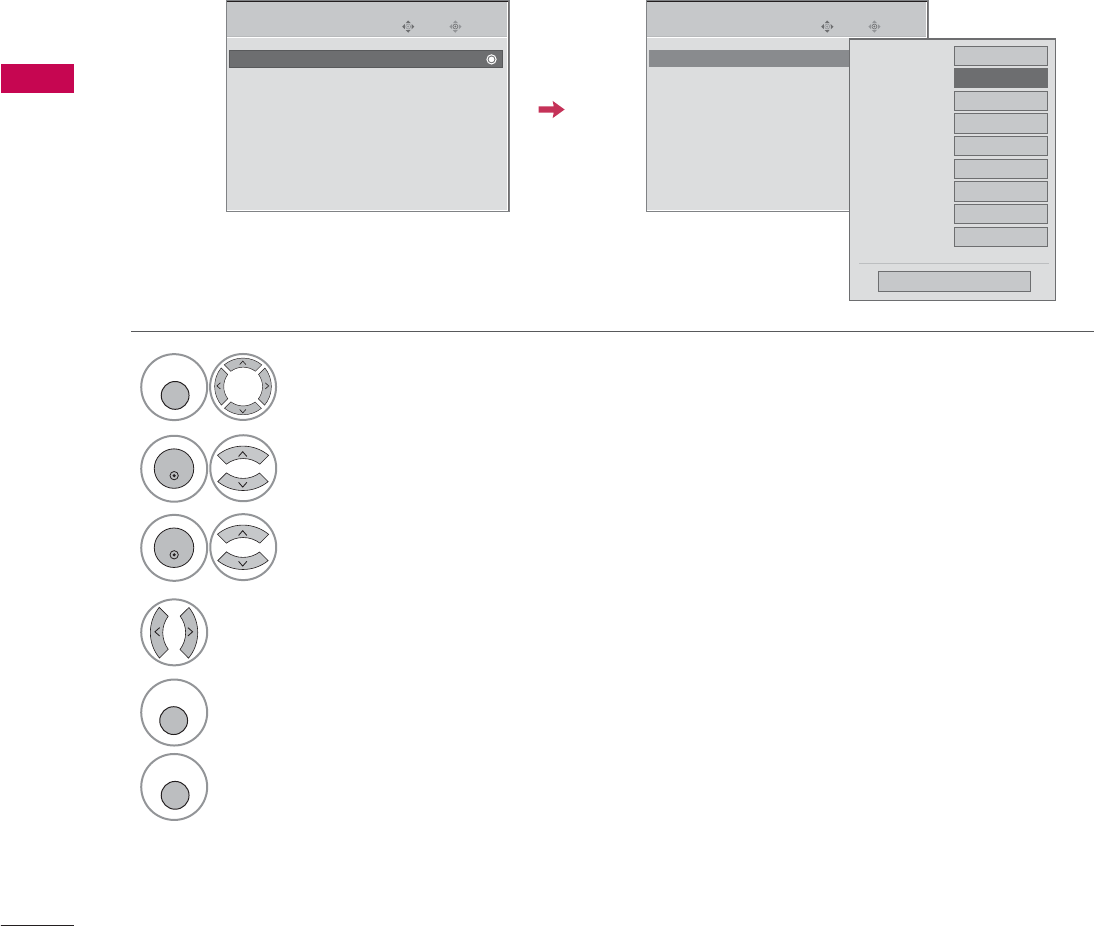
45
Select OSD L
L
anguage S
S
etting or
Audio L
L
anguage S
S
etting.
Start Auto T
T
uning.
Select your desired language.
1
3
ENTER
1
ENTER
2
Auto Tuning can change channel map.
Do you want to start Auto Tuning?
Enter
Exit
Enter
RETURN
Step4. Auto Tuning
ExitEnter
RETURN
Step3. Option Setting
1. OSD Language Setting
F
English
G
2. Audio Language Setting French
Step3. Option setting
Step4. Auto Tuning
• You can also adjust Initial S
S
etting in the OPTION menu.
Enter
Move
OPTION
Initial Setting
E
Select OPTION.
Select Initial S
S
etting.
1
MENU
3
2
ENTER
ENTER
NOTE
!
WATCHING TV / CHANNEL CONTROL
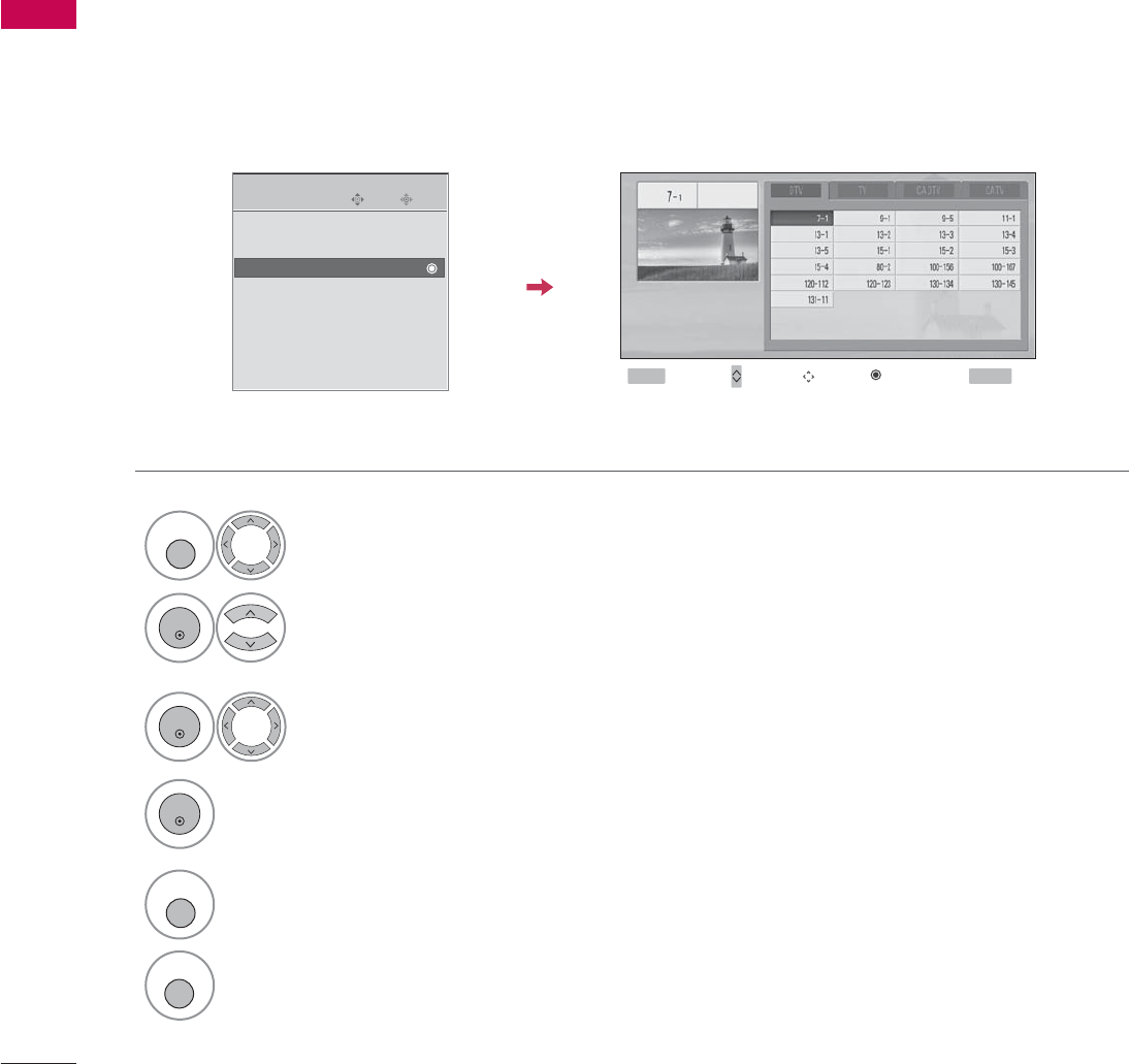
50
CHANNEL SETUP
WATCHING TV / CHANNEL CONTROL
Select a channel.
Select channel you want to add or
delete.
3
ENTER
4
ENTER
From the default channel list created from the Auto Tuning channel search, you can create two different types
of channel lists in memory: “custom list” and “favorite channel list”.
A custom list can be created by toggling each channel on or off with ENTER button. The channels in the Custom
List are displayed in black and the channels deleted from the Custom List are displayed in gray.
Once a channel is highlighted you can add or delete the channel by referring to the small window at the top-
left corner of the screen.
Channel Editing
Enter
Move
CHANNEL
Auto Tuning
Manual Tuning
Channel Edit
Select CHANNEL.
1
MENU
2
ENTER
Select Channel E
E
dit.
RETURN
Return to TV viewing
Return to the previous menu.
5
MENU
Add/Delete
Move Page
CH Navigate
Previous
MENU Exit
RETURN
WATCHING TV / CHANNEL CONTROL
53
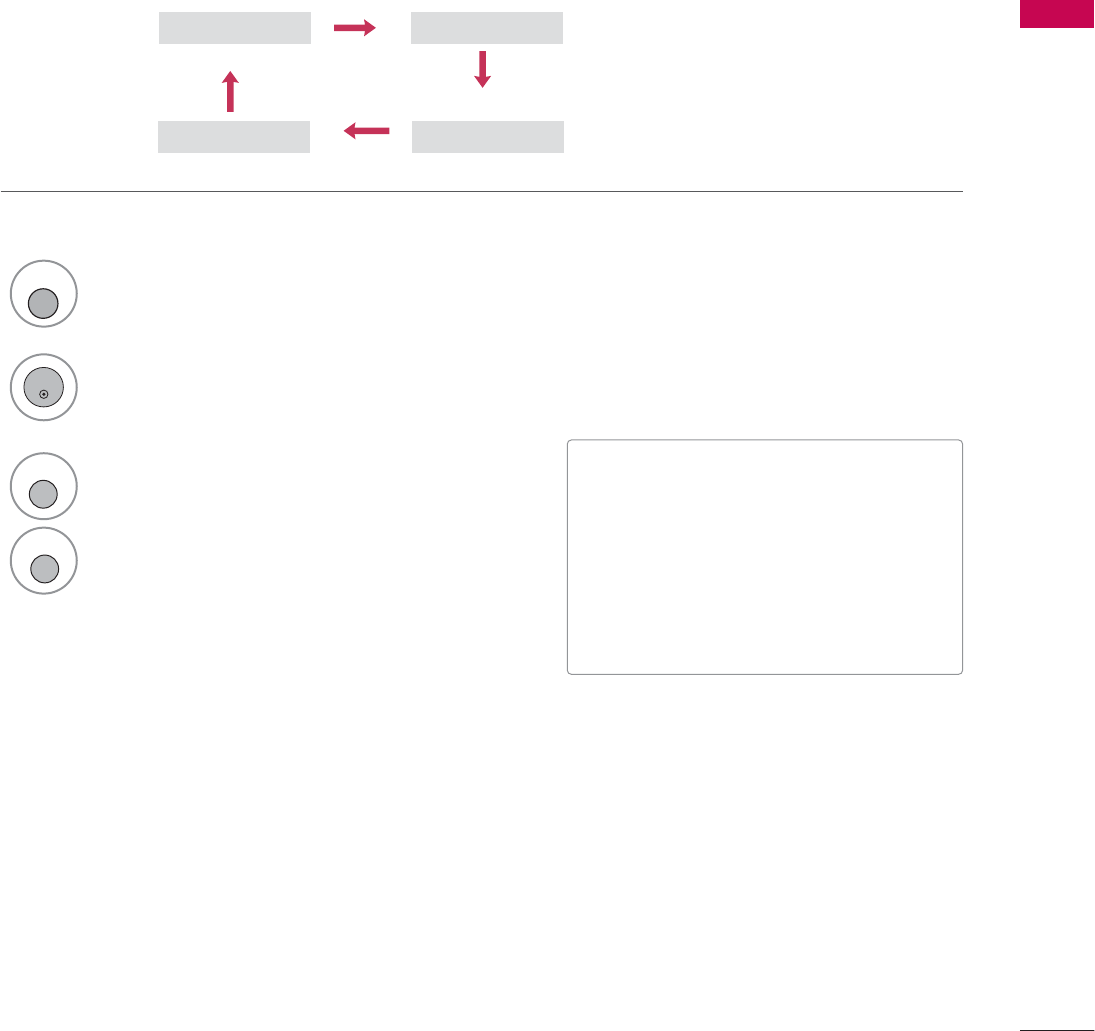
AV MODE
You can select the optimal images and sounds when connecting AV devices to external input.
1
AV MODE
2
Off Cinema
Game Sport
Press the AV M
M
ODE button repeatedly to select the desired source.
ENTER
3
RETURN
Return to the previous menu.
MENU
Return to TV viewing
■If you select Cinema Mode in AV mode,
Cinema mode will be selected both for
Picture and Sound Mode in PICTURE and
AUDIO menu respectively.
■If you select “Off” in AV mode, the picture
and image which you initially set will be
selected.
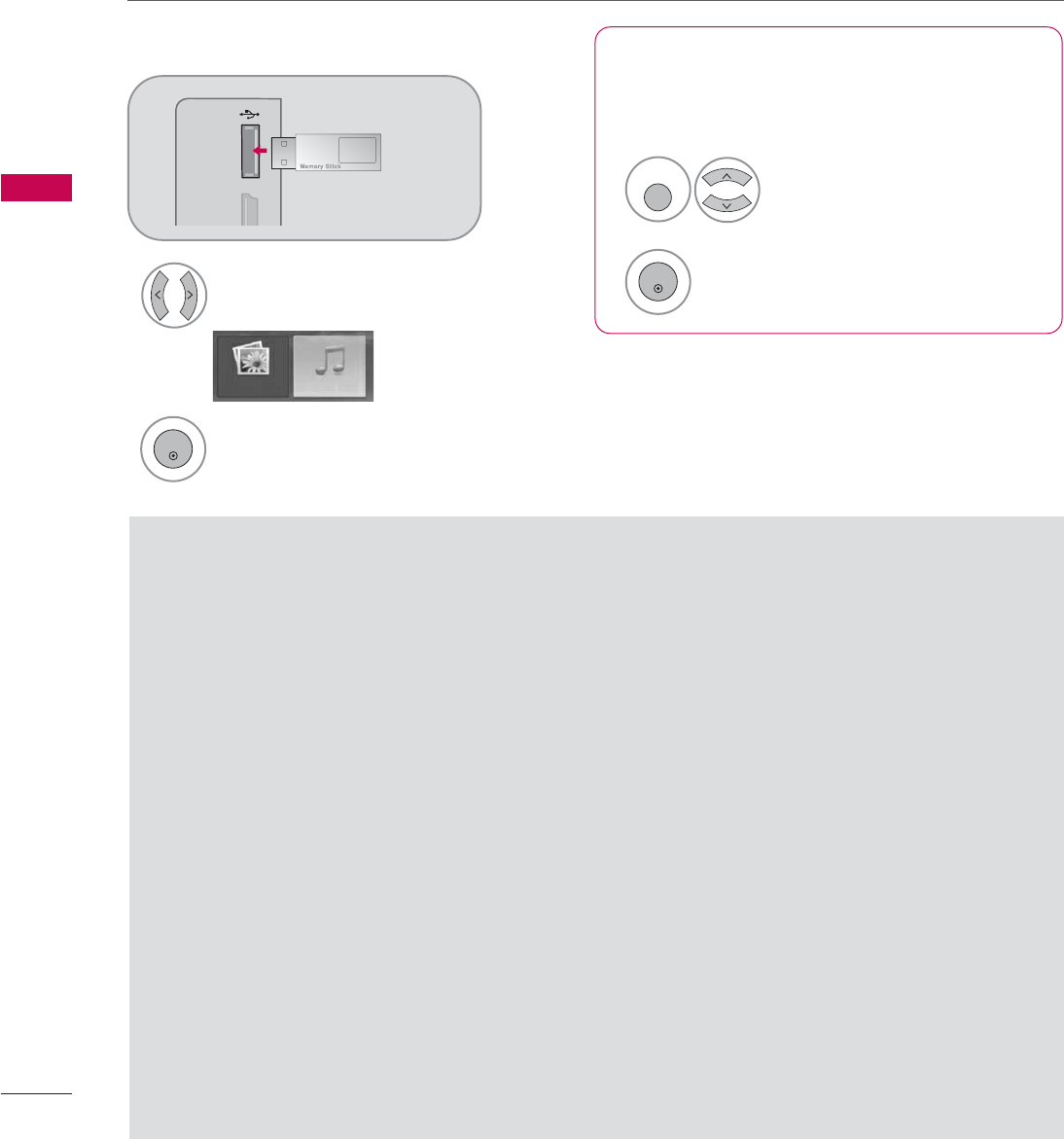
ENTRY MODES
MEDIA HOST
56
USB
When you connect a USB device, this screen is displayed, automatically.
In USB device, you can not add a new folder or delete the existing folder.
Precautions when using the USB device
GOnly a USB storage device is recognizable.
GIf the USB storage device is connected through a
USB hub, the device is not recognizable.
GA USB storage device using an automatic recogni-
tion program may not be recognized.
GA USB storage device which uses its own driver
may not be recognized.
GIn case of a card reader, up to four memory cards
are concurrently recognizable.
GThe recognition speed of a USB storage device
may depend on each device.
GPlease do not turn off the TV or unplug the USB
device when the connected USB storage device is
working. When such device is suddenly separated
or unplugged, the stored files or the USB storage
device may be damaged.
GPlease do not connect the USB storage device
which was artificially maneuvered on the PC. The
device may cause the product to malfunction or
fail to be played. Never forget to use only a USB
storage device which has normal music files or
image files.
GPlease use only a USB storage device which was
formatted as a FAT32 file system provided with the
Windows operating system. In case of a storage
device formatted as a different utility program
which is not supported by Windows, it may not be
recognized.
GPlease connect power to a USB storage device
which requires an external power supply. If not,
the device may not be recognized.
GPlease connect a USB storage device with cable is
offered by USB maker. If connected with cable is
not offered by USB maker or an excessively long
cable, the device may not be recognized.
GSome USB storage devices may not be supported
or operated smoothly.
GIf the name of a folder or file is too long, it will not
be displayed or recognized.
GPlease backup the important file because a data of
USB device may be damaged. Data management is
consumer's responsibility and in consequence the
manufactures does not cover the product bearing
data damage.
When removing the USB device
Connect the USB device to the USB I
I
N
jacks on the side of TV.
3
Select PHOTO L
L
IST or MUSIC LIST
1
USB
SERVUCE ONLY
MI IN 3
PHOTO LIST MUSIC LIST
Select USB E
E
ject.
Select the USB EJECT menu before removing the
USB device.
2
ENTER
1
Q. MENU
2
ENTER
■
This feature is only for 32/37/42/47/52LG50/60/70, 50/60PG60F.
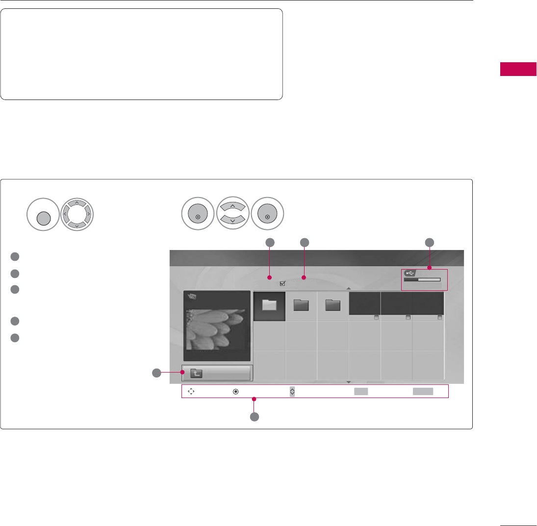
PHOTO LIST
MEDIA HOST
57
It’s available to playback the photo file(*.jpg) in the USB device.
The On Screen Display may be different from your set. Images are an example to assist with the TV operation.
Screen Components
Moves to upper level file
Current page/Total pages
Total number of marked
thumbnail photos
Usable USB memory
Corresponding buttons on
the remote control
PHOTO (*.JPEG) supporting file
Baseline: width<=4800, height is no limit
• You can play JPEG files only.
• Only baseline scan is supported among JPEG.
• Non-supported files are displayed in the form of icon.
USB Device
Page 2/3 No Marked
PHOTO LIST
Up Folder
Free Space 150MB
Navigate PopUp Menu Move Page Mark Exit
1366x768, 125KB
2 3 4
1
Select USB.Select Photo L
L
ist.
2
Drive1
1
MENU
ENTER
ENTER
1
2
3
4
5
KY104 KY105 KY106
CH FAV RETURN
5
MEDIA HOST
58
USB
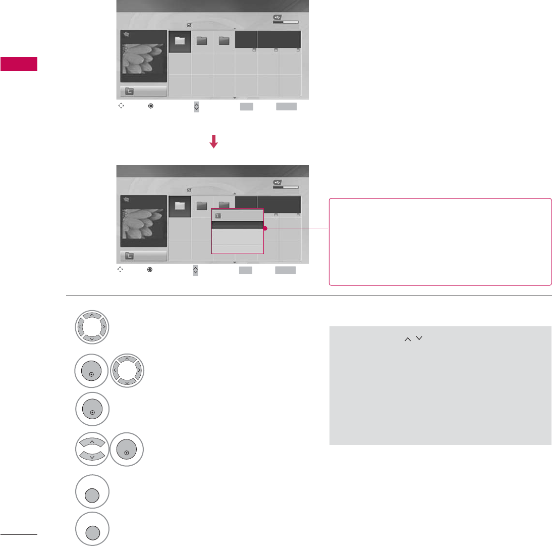
Photo Selection and PopUp Menu
USB Device
Page 2/3
No Marked
PHOTO LIST
Up Folder
Free Space 150MB
1366x768, 125KB
USB Device
Page 2/3
No Marked
PHOTO LIST
Up Folder
Free Space 150MB
1366x768, 125KB
1366x768, 125KB
View
Mark All
Delete
Cancel
GView: Display the selected item.
GMark A
A
ll: Mark all photos on the screen.
GUnmark A
A
ll: Deselect all marked photos.
GDelete: Delete the selected photo item.
GCancel: Close the pop-up menu.
Select the target folder or drive.
Select the desired photos.
2
Show the PopUp menu.
3
1
• Use the CH button to navigation in the
thumbnail photo page.
• Use the FAV button to mark or unmark a photo.
When one or more photos are marked, you can
view individual photos or a slide show of the
marked photos. If no photos are marked, you
can view all photos individually or all photos in
the folder in a slide show.
Drive1
Drive1
4Select the desired PopUp menu.
ENTER
ENTER
ENTER
5Return to TV viewing
RETURN
Return to the previous menu.
MENU
Navigate Move Page Mark Exit
CH FAV RETURN
PopUp Menu
Navigate Move Page Mark Exit
CH FAV RETURN
PopUp Menu
KY104 KY105 KY106
KY104 KY105 KY106
MEDIA HOST
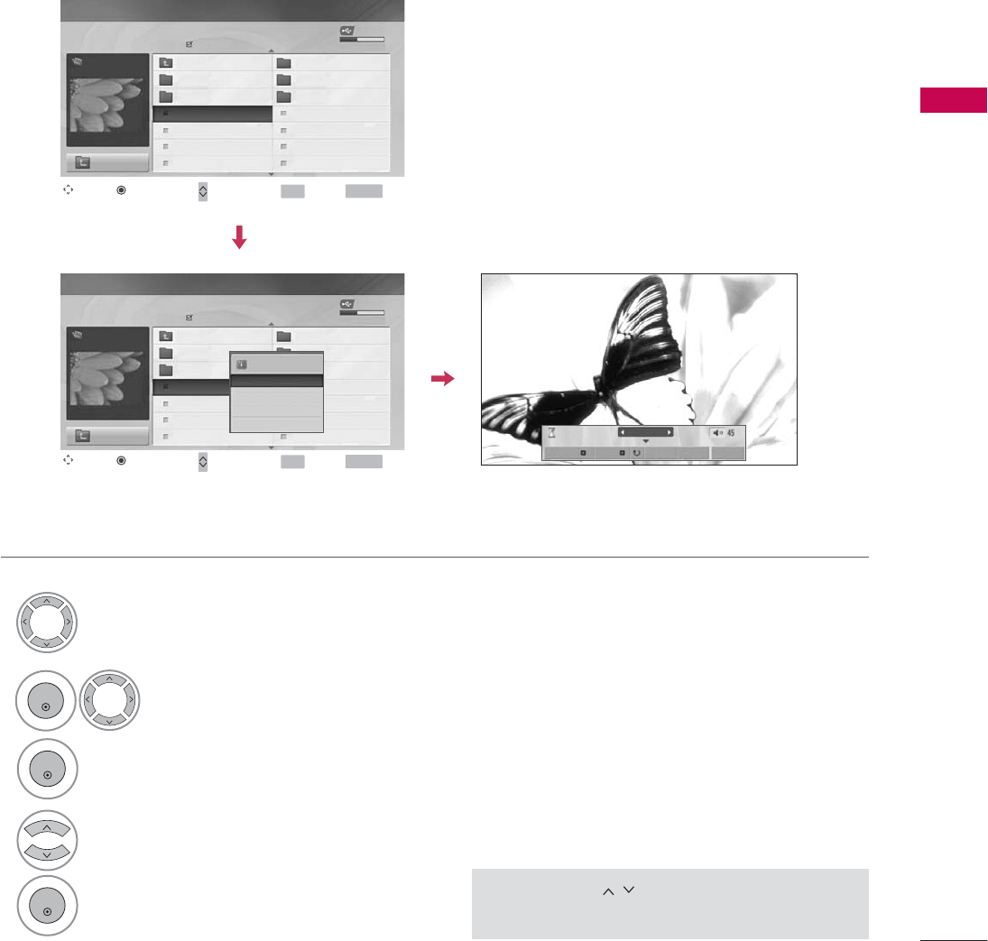
59
Set up the menu in Full-Sized Screen
You can change the settings to display photos stored on a USB device, on a full-sized screen.
Detailed operations are available on full-sized photo view screen.
• Use the CH button to navigation in the
thumbnail photo page.
USB Device
Page 2/3
No Marked
PHOTO LIST
Up Folder
Free Space 150MB
1366x768, 125KB
KR101
KR102
JMJ001
JMJ002
JMJ003
JMJ004
KR103
KR104
KR105
JMJ005
JMJ006
JMJ007
JMJ008
Up Folder
1366x768, 125KB
View
Mark All
Delete
Cancel
The aspect ratio of a photo may change the size of
the photo displayed on the screen in full size.
1/17
Slideshow BGM Delete Option Hide
USB Device
Page 2/3
No Marked
PHOTO LIST
Up Folder
Free Space 150MB
1366x768, 125KB
KR101
KR102
JMJ001
JMJ002
JMJ003
JMJ004
KR103
KR104
KR105
JMJ005
JMJ006
JMJ007
JMJ008
Up Folder
Drive1
Drive1
Select the target folder or drive.
Select the desired photos.
show the PopUp menu.
5
Select View
The selected photo is displayed in
full size.
2
3
1
4
ENTER
ENTER
ENTER
Navigate Move Page Mark Exit
CH FAV RETURN
PopUp Menu
Navigate Move Page Mark Exit
CH FAV RETURN
PopUp Menu
MEDIA HOST
60
USB
The aspect ratio of a photo may change
the size of the photo displayed on the
screen in full size.
1/17
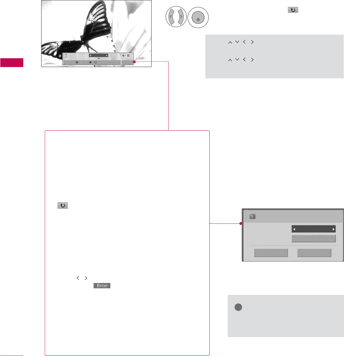
Slideshow BGM Delete Option Hide
Select the Slideshow, BGM, (Rotate),
Delete,Option, or Hide.
Press
F G
G
to set the time interval between slides.
Slide Speed Fast
Cancel
Music
Music Folder
ENTER
• Use button to select the previous
or next photo.
• Use button to select and control
the menu on the full-sized screen.
ENTER
6
GSlideshow : When no picture is selected, all photos in
the current folder are displayed during slide show.
When selected, the selected photos are displayed dur-
ing slide show.
■Set the time interval of the slide show in Option.
GBGM : Listen to music while viewing photos in full size.
■Set the BGM device and album in Option.
G(Rotate) : Rotate photos.
■Rotates the photo 90°, 18 0 °, 270°, 360°clockwise.
■A slide show continues for a maximum of 4 hours.
After 4 hours, the slide show will end and go to TV
mode or external input mode.
GDelete : Delete photos.
GOption : Set values for Slide S
S
peed and Music
Folder.
■Use button and ENTER button to set values.
Then go to and press ENTER to save the set-
tings.
■You cannot change Music F
F
older while BGM is
playing.
GHide : Hide the menu on the full-sized screen.
■To see the menu again on the full-sized screen, press
ENTER button to display.
NOTE
!
GIf it is Progressive JPEG format,
some photos may be not decorded.
PICTURE CONTROL
70
PICTURE IMPROVEMENT TECHNOLOGY
PICTURE CONTROL
Fresh Contrast: Optimizes the contrast automatically according to the brightness of the reflection.
Fresh Color: Adjusts the color of the reflection automatically to reproduce as close as possible natural colors.
Noise Reduction: Removes interference up to the point where it does not damage the original picture.
Gamma: High gamma values display whitish images and low gamma values display high contrast images.
Select PICTURE.
Select Advanced C
C
ontrol.
Select Fresh C
C
ontrast, Fresh C
C
olor,
Noise R
R
eduction, or Gamma.
1
MENU
3
2
ENTER
ENTER
Enter
Move
PICTURE
Enter
Move
PICTURE
EE
• Advanced Control
• Picture Reset
Screen
TruMotion Demo
• Advanced Control
• Picture Reset
Screen
TruMotion Demo
Color Temperature
Medium
Fresh Contrast
F Off G
Fresh Color
Off
Noise Reduction
Auto
Gamma
Medium
Black Level
Low
Eye Care
Off
Film Mode
Off
TruMotion
High
Close
5
RETURN
Return to the previous menu.
MENU
Return to TV viewing
Select your desired options.
4
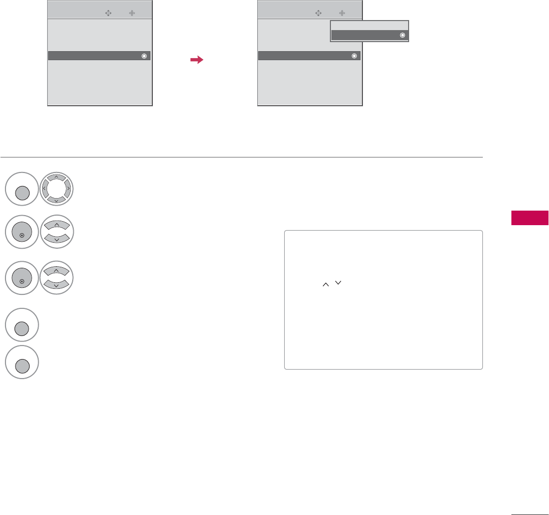
PARENTAL CONTROL / RATING
109
KEY LOCK
The TV can be set up so that it can only be used with the remote control.
This feature can be used to prevent unauthorized viewing by locking out the front panel controls.
This TV is programmed to remember which option it was last set to even if you turn the TV off.
Select OPTION.
Select Key L
L
ock.
Enter
Move
OPTION
Enter
Move
OPTION
1
MENU
2
ENTER
Language : English
Input Label
Simplink : On
Key Lock : Off
Caption : Off
Set ID : 1
Initial Setting
Language : English
Input Label
Simplink : On
Key Lock : Off
Caption : Off
Set ID : 1
Initial Setting
Off
On
Select O n or Off.
3
ENTER
■In Key L
L
ock ‘O n’, if the TV is turned
off, press the r/ I, INPUT, CH Dor E
button on the TV or POWER, INPUT,
CH or NUMBER buttons on the
remote control.
■With the Key L
L
ock O
O
n, the display
‘Key L
L
ock O
O
n’ appears on the screen
if any button on the front panel is
pressed while viewing the TV.
4
RETURN
Return to the previous menu.
MENU
Return to TV viewing
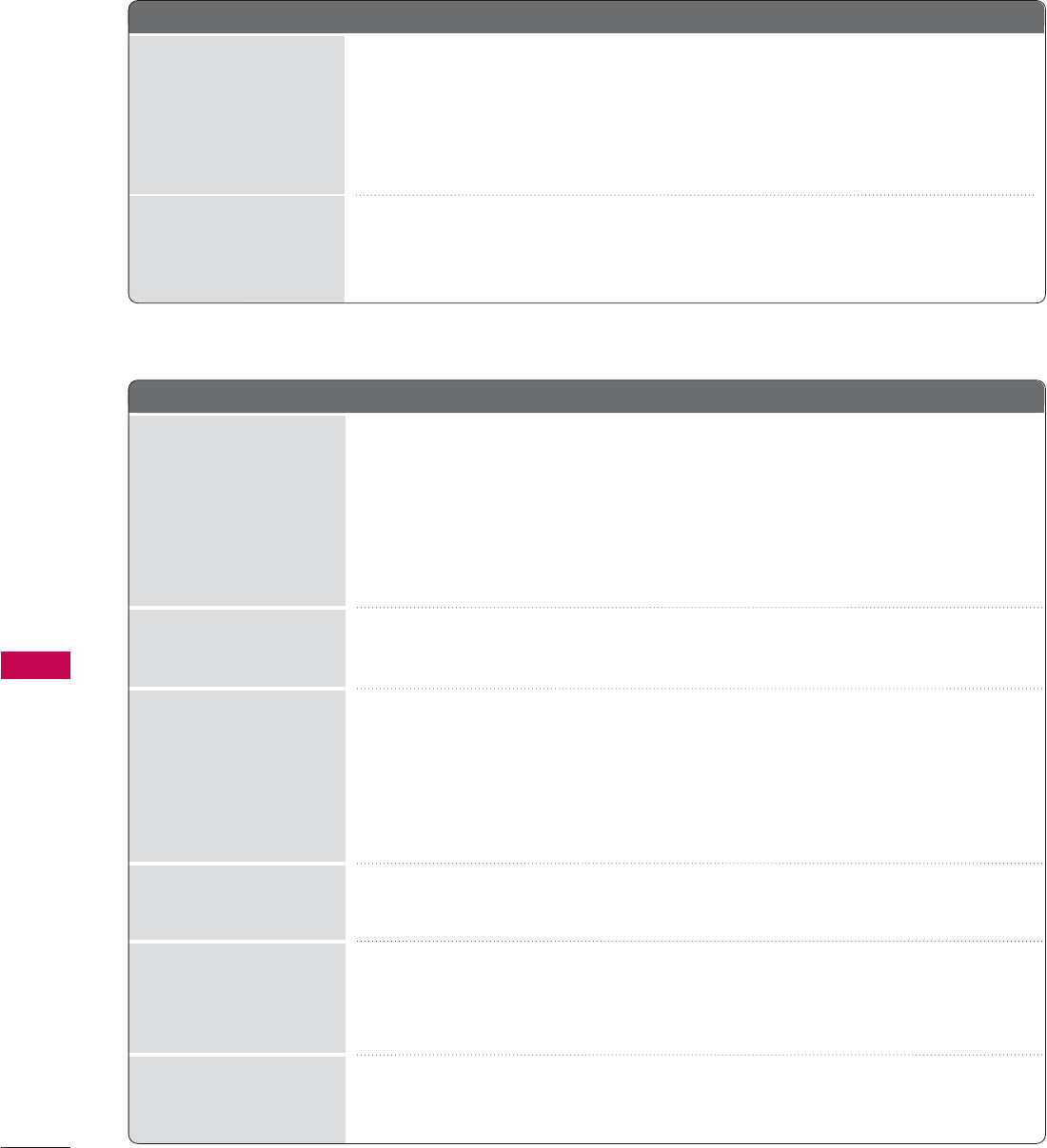
APPENDIX
110
APPENDIX
TROUBLESHOOTING
The o
o
peration d
d
oes n
n
ot w
w
ork n
n
ormally.
The v
v
ideo f
f
unction d
d
oes n
n
ot w
w
ork.
No picture &No sound
No or poor color
or poor picture
Poor reception on
some channels
Lines or streaks
in pictures
Horizontal/vertical bars
or picture shaking
Picture appears slowly
after switching on
The remote control
doesn’t work
Power is suddenly
turned off
■Check to see if there is any object between the product and the remote control
causing obstruction. Ensure you are pointing the remote control directly at the TV.
■Ensure that the batteries are installed with correct polarity (+ to +, - to -).
■Ensure that the correct remote operating mode is set: TV, VCR etc.
■Install new batteries.
■Is the sleep timer set?
■Check the power control settings. Power interrupted.
■No broadcast on station tuned with Auto off activated.
■Check whether the product is turned on.
■Try another channel. The problem may be with the broadcast.
■Is the power cord inserted into wall power outlet?
■Check your antenna direction and/or location.
■Test the wall power outlet, plug another product’s power cord into the outlet
where the product’s power cord was plugged in.
■This is normal, the image is muted during the product startup process. Please
contact your service center, if the picture has not appeared after five minutes.
■Adjust Color in menu option.
■Keep a sufficient distance between the product and the VCR.
■Try another channel. The problem may be with the broadcast.
■Are the video cables installed properly?
■Activate any function to restore the brightness of the picture.
■Check for local interference such as an electrical appliance or power tool.
■Station or cable product experiencing problems, tune to another station.
■Station signal is weak, reorient antenna to receive weaker station.
■Check for sources of possible interference.
■Check antenna (Change the direction of the antenna).
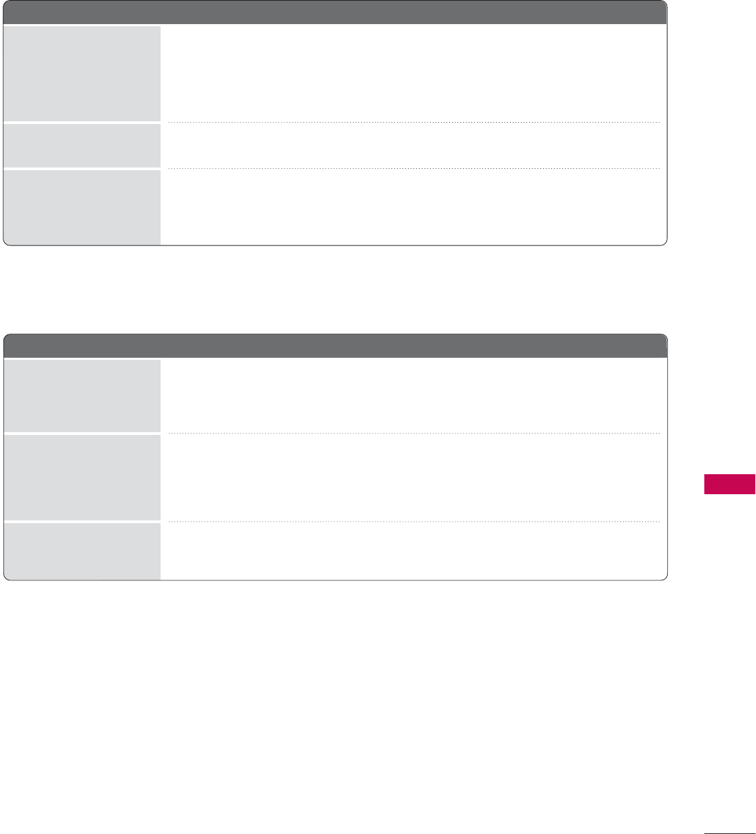
APPENDIX
111
There i
i
s a
a
p
p
roblem i
i
n P
P
C m
m
ode. (
(
Only P
P
C m
m
ode a
a
pplied)
■Adjust resolution, horizontal frequency, or vertical frequency.
■Check the input source.
■Work the Auto configure or adjust clock, phase, or H/V position. (Option)
■Check the signal cable.
■Reinstall the PC video card.
The signal is out of range
Screen color is unstable
or single color
Vertical bar or stripe on
background &
Horizontal Noise &
Incorrect position
■Press the VOL or VOLUME button.
■Sound muted? Press MUTE button.
■Try another channel. The problem may be with the broadcast.
■Are the audio cables installed properly?
■Adjust Balance in menu option.
■A change in ambient humidity or temperature may result in an unusual noise
when the product is turned on or off and does not indicate a fault with the
product.
Picture OK & No sound
Unusual sound from
inside
the product
No output from one
of the speakers
The a
a
udio f
f
unction d
d
oes n
n
ot w
w
ork.

APPENDIX
112
MAINTENANCE
Early malfunctions can be prevented. Careful and regular cleaning can extend the amount of time you can
enjoy your new TV.
Caution: Be sure to turn the power off and unplug the power cord before you begin any cleaning.
Cleaning the Screen
Here’s a great way to keep the dust off your screen for a while. Wet a soft cloth in a mixture of lukewarm
water and a little fabric softener or dish washing detergent. Wring the cloth until it’s almost dry, and then
use it to wipe the screen.
Make sure the excess water is off the screen, and then let it air-dry before you turn on your TV.
Cleaning the Cabinet
■To remove dirt or dust, wipe the cabinet with a soft, dry, lint-free cloth.
■Please be sure not to use a wet cloth.
Extended Absence
G If you expect to leave your TV dormant for a long time (such as a vacation), it’s a good idea to unplug
the power cord to protect against possible damage from lightning or power surges.
CAUTION
2
1
APPENDIX
113
PRODUCT SPECIFICATIONS
■The specifications shown above may be changed without prior notice for quality improvement.
MODELS
AC100-240V ~50/60Hz
NTSC-M, ATSC, 64 & 256 QAM
VHF 2-13, UHF 14-69, CATV 1-135, DTV 2-69, CADTV 1-135
75 ohm
32 ~104°F (0 ~40°C)
Less than 80%
-4 ~140°F (-20 ~60°C)
Less than 85%
Dimensions
(Width x Height x Depth)
Weight
Power requirement
Television System
Program Coverage
External Antenna Impedance
Environment condition
With stand
Without stand
With stand
Without stand
Operating Temperature
Operating Humidity
Storage Temperature
Storage Humidity
26LG30
(26LG30-UA)
32LG30
(32LG30-UA)
MODELS 37LG30
(37LG30-UA)
42LG30
(42LG30-UA)
26.1 x 20.0 x 9.1 inches
663.8 x 508.2 x 231.9 mm
26.1 x 17.7 x 3.6 inches
663.8 x 449.8 x 91.4 mm
22.3 pounds / 10.1 kg
19.0 pounds / 8.6 kg
31.8 x 23.8 x 9.1 inches
807.7 x 604.2 x 232.0 mm
31.8 x 21.4 x 4.0 inches
807.7 x 544.1 x 101.0 mm
29.1 pounds / 13.2 kg
25.4 pounds / 11.5 kg
Dimensions
(Width x Height x Depth)
Weight
With stand
Without stand
With stand
Without stand
36.2 x 26.9 x 11.6 inches
919.6 x 682.3 x 293.8 mm
36.2 x 24.0 x 4.5 inches
919.6 x 610.3 x 114.3 mm
45.6 pounds / 20.7 kg
37.9 pounds / 17.2 kg
40.7 x 29.2 x 11.6 inches
1032.8 x 742.3 x 293.8 mm
40.7 x 26.4 x 4.5 inches
1032.8 x 670.1 x 115.1 mm
51.8 pounds / 23.5 kg
44.1 pounds / 20.0 kg
MODELS 37LG50
(37LG50-UA)
42LG50
(42LG50-UA)
Dimensions
(Width x Height x Depth)
Weight
With stand
Without stand
With stand
Without stand
36.9 x 27.0 x 11.6 inches
936.4 x 684.4 x 293.8 mm
36.9 x 24.1 x 3.5 inches
936.4 x 612.8 x 88.0 mm
40.3 pounds / 18.3 kg
34.4 pounds / 15.6 kg
36.9 x 27.0 x 11.6 inches
936.4 x 684.4 x 293.8 mm
36.9 x 24.1 x 3.5 inches
936.4 x 612.8 x 88.0 mm
40.3 pounds / 18.3 kg
34.4 pounds / 15.6 kg
MODELS 47LG50
(47LG50-UA)
52LG50
(52LG50-UA)
Dimensions
(Width x Height x Depth)
Weight
With stand
Without stand
With stand
Without stand
45.4 x 31.8 x 12.8 inches
1153.7 x 807.2 x 326.0 mm
45.4 x 29.0 x 4.1 inches
1153.7 x 734.5 x 103.0 mm
85.1 pounds / 38.6 kg
77.0 pounds / 34.9 kg
50.9 x 35.1 x 13.5 inches
1291.7 x 892.2 x 342.9 mm
50.9 x 32.2 x 4.5 inches
1291.7 x 817.0 x 115.3 mm
87.1 pounds / 39.5 kg
77.0 pounds / 34.9 kg
APPENDIX
114
APPENDIX
■The specifications shown above may be changed without prior notice for quality improvement.
MODELS
AC100-240V ~50/60Hz
NTSC-M, ATSC, 64 & 256 QAM
VHF 2-13, UHF 14-69, CATV 1-135, DTV 2-69, CADTV 1-135
75 ohm
32 ~104°F (0 ~40°C)
Less than 80%
-4 ~140°F (-20 ~60°C)
Less than 85%
Dimensions
(Width x Height x Depth)
Weight
Power requirement
Television System
Program Coverage
External Antenna Impedance
Environment condition
With stand
Without stand
With stand
Without stand
Operating Temperature
Operating Humidity
Storage Temperature
Storage Humidity
32LG60
(32LG60-UA)
37LG60
(37LG60-UA)
42LG60
(42LG60-UA)
MODELS 47LG60
(47LG60-UA)
52LG60
(52LG60-UA)
31.8 x 23.9x 9.8 inches
806.6 x 606.5 x 249.0mm
31.8 x 21.7 x 3.1 inches
806.6 x 552.3 x 79.0 mm
30.2 pounds / 13.7 kg
24.7 pounds / 11.2 kg
36.5 x 27.3 x 11.0 inches
927.0 x 692.8 x 280.5 mm
36.5 x24.8 x 3.5 inches
927.0 x 630.0 x 88.0 mm
44.1 pounds / 20.0 kg
35.3 pounds / 16.0 kg
40.7 x 29.5 x 11.3 inches
1033.4 x 750.0 x 287.6 mm
40.7 x 27.0x 3.5 inches
1033.4 x 686.8 x 88.5 mm
54.9 pounds / 24.9 kg
45.0 pounds / 20.4 kg
Dimensions
(Width x Height x Depth)
Weight
With stand
Without stand
With stand
Without stand
45.4 x 31.8 x 12.8 inches
1153.7 x 807.2 x 326.0 mm
45.4 x 29.0 x 4.1 inches
1153.7 x 734.5 x 103.0 mm
85.1 pounds / 38.6 kg
77.0 pounds / 34.9 kg
50.9 x 35.1 x 13.5 inches
1291.7 x 892.2 x 342.9 mm
50.9 x 32.2 x 4.5 inches
1291.7 x 817.0 x 115.3 mm
87.1 pounds / 39.5 kg
77.0 pounds / 34.9 kg
MODELS 32LG70
(32LG70-UA)
42LG70
(42LG70-UA)
Dimensions
(Width x Height x Depth)
Weight
With stand
Without stand
With stand
Without stand
31.8 x 23.9x 9.8 inches
806.6 x 606.5 x 249.0mm
31.8 x 21.7 x 3.1 inches
806.6 x 552.3 x 79.0 mm
30.2 pounds / 13.7 kg
24.7 pounds / 11.2 kg
40.7 x 29.5 x 11.3 inches
1033.4 x 750.0 x 287.6 mm
40.7 x 27.0x 3.5 inches
1033.4 x 686.8 x 88.5 mm
54.9 pounds / 24.9 kg
45.0 pounds / 20.4 kg
MODELS 47LG70
(47LG70-UA)
52LG70
(52LG70-UA)
Dimensions
(Width x Height x Depth)
Weight
With stand
Without stand
With stand
Without stand
45.4 x 31.8 x 12.8 inches
1153.7 x 807.2 x 326.0 mm
45.4 x 29.0 x 4.1 inches
1153.7 x 734.5 x 103.0 mm
85.1 pounds / 38.6 kg
77.0 pounds / 34.9 kg
50.9 x 35.1 x 13.5 inches
1291.7 x 892.2 x 342.9 mm
50.9 x 32.2 x 4.5 inches
1291.7 x 817.0 x 115.3 mm
87.1 pounds / 39.5 kg
77.0 pounds / 34.9 kg
APPENDIX
115
■The specifications shown above may be changed without prior notice for quality improvement.
MODELS
AC100-240V ~50/60Hz
NTSC-M, ATSC, 64 & 256 QAM
VHF 2-13, UHF 14-69, CATV 1-135, DTV 2-69, CADTV 1-135
75 ohm
32 ~104°F (0 ~40°C)
Less than 80%
-4 ~140°F (-20 ~60°C)
Less than 85%
Dimensions
(Width x Height x Depth)
Weight
Power requirement
Television System
Program Coverage
External Antenna Impedance
Environment condition
With stand
Without stand
With stand
Without stand
Operating Temperature
Operating Humidity
Storage Temperature
Storage Humidity
42PG10
(42PG10-UA)
50PG10
(50PG10-UA)
MODELS 42PG20
(42PG20-UA)
50PG20
(50PG20-UA)
41.3 x 30.2 x 12.2 inches
1048.0 x 766.0 x 310.0 mm
41.3 x 28.1 x 3.3 inches
1048.0 x 713.0 x 83.5 mm
61.7 pounds / 28.0 kg
54.2 pounds / 24.6 kg
48.9 x 34.9 x 14.6 inches
1242.0 x 887.6 x 370.0 mm
48.9 x 32.6 x 3.5 inches
1242.0 x 827.2 x 88.0 mm
86.6 pounds / 39.3 kg
76.3 pounds / 34.6 kg
Dimensions
(Width x Height x Depth)
Weight
With stand
Without stand
With stand
Without stand
41.3 x 30.2 x 12.2 inches
1048.0 x 766.0 x 310.0 mm
41.3 x 28.1 x 3.3 inches
1048.0 x 713.0 x 83.5 mm
61.7 pounds / 28.0 kg
54.2 pounds / 24.6 kg
48.9 x 34.9 x 14.6 inches
1242.0 x 887.6 x 370.0 mm
48.9 x 32.6 x 3.5 inches
1242.0 x 827.2 x 88.0 mm
86.6 pounds / 39.3 kg
76.3 pounds / 34.6 kg
MODELS 50PG60F-UA
(50PG60F-UA)
60PG60F-UA
(60PG60F-UA)
Dimensions
(Width x Height x Depth)
Weight
With stand
Without stand
With stand
Without stand
48.9 x 34.9 x 14.6 inches
1242.0 x 887.6 x 370.0 mm
48.9 x 32.6 x 3.5 inches
1242.0 x 827.2 x 88.0 mm
86.6 pounds / 39.3 kg
76.3 pounds / 34.6 kg
57.3 x 38.8 x 16.3 inches
1455.0 x 985.0 x 414.0 mm
57.3 x 38.5 x 15.8 inches
1455.0 x 914.8 x 82.8 mm
137.6 pounds / 62.4 kg
127.8 pounds / 58.0 kg
MODELS 50PG70F-UA
(50PG70F-UA)
60PG70F-UA
(60PG70F-UA)
Dimensions
(Width x Height x Depth)
Weight
With stand
Without stand
With stand
Without stand
48.9 x 34.9 x 14.6 inches
1242.0 x 887.6 x 370.0 mm
48.9 x 32.6 x 3.5 inches
1242.0 x 827.2 x 88.0 mm
86.6 pounds / 39.3 kg
76.3 pounds / 34.6 kg
57.5 x 38.5 x 15.8 inches
1459.4 x 976.8 x 401.0 mm
57.5 x 38.5 x 15.8 inches
1459.4 x 914.8 x 82.8 mm
86.6 pounds / 39.3 kg
76.3 pounds / 34.6 kg

APPENDIX
116
PROGRAMMING THE REMOTE CONTROL
APPENDIX
The provided universal remote control can be programmed to operate most remote-controllable devices.
Note that the remote may not control all models of other brands.
Programming a code into a remote mode
Testing your remote control.
To find out whether your remote control can operate other components without programming, turn on a
component such as a STB and press the corresponding mode button (such as a STB) on the remote con-
trol, while pointing at the component. Test the POWER and C H buttons to see if the component
responds correctly. If the component does not operate correctly, the remote control requires programming
to operate the device.
Switch on the component to be programmed, then press the corresponding mode button (such as STB) on
the remote control. The remote control button of the desired device is illumintated.
Press the MENU and MUTE buttons simultaneously, the remote control is ready to be programmed with the
code.
Enter a code number using the number buttons on the remote control. Programming code numbers for the
corresponding component can be found on the following pages. If the code is correct, the device will turn
off.
Press the MENU button to store the code.
Test the remote control functions to see if the component responds correctly. If not, repeat from step 2.
2
3
4
5
6
1

APPENDIX
117
Brand Codes Brand Codes Brand Codes
AIWA 034
AKAI 016 043 046 124
125 146
AMPRO 072
ANAM 031 033 103
AUDIO DYNAMICS
012 023 039 043
BROKSONIC 035 037 129
CANON 028 031 033
CAPEHART 108
CRAIG 003 040 135
CURTIS MATHES 031 033 041
DAEWOO 005 007 010 064
065 108 110 111
112 116 117 119
DAYTRON 108
DBX 012 023 039 043
DYNATECH 034 053
ELECTROHOME 059
EMERSON 006 017 025 027
029 031 034 035
036 037 046 101
129 131 138 153
FISHER 003 008 009 010
FUNAI 034
GE 031 033 063 072
107 109 144 147
GO VIDEO 132 136
HARMAN KARDON 012 045
HITACHI 004 018 026 034
043 063 137 150
INSTANTREPLAY 031 033
JCL 031 033
JCPENNY 012 013 015 033
040 066 101
JENSEN 043
JVC 012 031 033 043
048 050 055 060
130 15 0 152
KENWOOD 014 034 039 043
047 048
LG (GOLDSTAR) 001 012 013 020
101 10 6 114 123
LLOYD 034
LXI 003 009 013 014
017 034 101 106
MAGIN 040
MAGNAVOX 031 033 034 041
067 068
MARANTZ 012 031 033 067
069
MARTA 101
MATSUI 027 030
MEI 031 033
MEMOREX 003 010 014 031
033 034 053 072
101 102 134 139
MGA 045 046 059
MINOLTA 013 020
MITSUBISHI 013 020 045 046
049 051 059 061
151
MTC 034 040
MULTITECH 024 034
NEC 012 023 039 043
048
NORDMENDE 043
OPTONICA 053 054
PANASONIC 066 070 074 083
133 140 145
PENTAX 013 020 031 033
063
PHILCO 031 034 067
PHILIPS 031 033 034 054
067 071 101
PILOT 101
PIONEER 013 021 048
PORTLAND 108
PULSAR 072
QUARTZ 011 014
QUASAR 033 066 075 145
RCA 013 020 033 034
040 041 062 063
107 109 140 144
145 147
REALISTIC 003 008 010 014
031 033 034 040
053 054 101
RICO 058
RUNCO 148
SALORA 014
SAMSUNG 032 040 102 104
105 107 10 9 112
113 115 120 122
125
SANSUI 022 043 048 135
SANYO 003 007 010 014
102 134
SCOTT 017 037 112 129
131
SEARS 003 008 009 010
013 014 017 020
031 042 073 081
101
SHARP 031 054 149
SHINTOM 024
SONY 003 009 031 052
056 057 058 076
077 078 149
SOUNDESIGN 034
STS 013
SYLVANIA 031 033 034 059
067
SYMPHONIC 034
TANDY 010 034
TATUNG 039 043
TEAC 034 039 043
TECHNICS 031 033 070
TEKNIKA 019 031 033 034
101
THOMAS 034
TMK 006
TOSHIBA 008 013 042 047
059 082 112 131
TOTEVISION 040 101
UNITECH 040
VECTOR RESEARCH
012
VICTOR 048
VIDEO CONCEPTS
012 034 046
VIDEOSONIC 040
WARDS 003 013 017 024
031 033 034 040
053 054 131
YAMAHA 012 034 039 043
ZENITH 034 048 056
058 072 080 101
VCR
APPENDIX
118
Remote Control Code
APPENDIX
Brand Codes Brand Codes Brand Codes
ALPHASTAR DSR 123
AMPLICA 050
BIRDVIEW 051 126 129
CHANNEL MASTER
013 014 015 018
036 055
CHAPARRAL 008 009 012 077
CITOH 054
CURTIS MATHES 050 145
DRAKE 005 006 007 010
011 052 112 116
141
DX ANTENNA 024 046 056 076
ECHOSTAR 038 040 057 058
093 094 095 096
097 098 099 100
122
ELECTRO HOME 089
EUROPLUS 114
FUJITSU 017 021 022 027
133 134
GENERAL INSTRUMENT
003 004 016 029
031 059 101
HITACHI 139 140
HOUSTON TRACKER
033 037 039 051
057 104
HUGHES 068
JANIEL 060 147
JERROLD 061
KATHREIN 108
LEGEND 057
LG 001
LUTRON 132
LUXOR 062 144
MACOM 010 059 063 064
065
MEMOREX 057
NEXTWAVE 028 124 125
NORSAT 069 070
PACE SKY SATELLITE
143
PANASONIC 060 142
PANSAT 121
PERSONAL CABLE 117
PHILIPS 071
PICO 105
PRESIDENT 019 102
PRIMESTAR 030 110 111
PROSAT 072
RCA 066 106
REALISTIC 043 074
SAMSUNG 123
SATELLITE SERVICE CO
028 035 047 057
085
SCIENTIFIC ATLANTA
032 138
SONY 103
STARCAST 041
SUPER GUIDE 020 124 125
TEECOM 023 026 075 087
088 090 107 130
137
TOSHIBA 002 127
UNIDEN 016 025 042 043
044 045 048 049
078 079 080 086
101 135 136
VIEWSTAR 115
WINEGARD 128 146
ZENITH 081 082 083 084
091 120
HDSTB
DVD
Brand Codes Brand Codes Brand Codes
APEX DIGITAL 022
DENON 020 014
GE 005 006
HARMAN KARDON 027
JVC 012
LG 001 010 016 025
MAGNAVOX 013
MARANTZ 024
MITSUBISHI 002
NAD 023
ONKYO 008 017
PANASONIC 003 009
PHILIPS 013
PIONEER 004 026
PROCEED 021
PROSCAN 005 006
RCA 005 006
SAMSUNG 011 015
SONY 007
THOMPSON 005 006
TOSHIBA 019 008
YAMAHA 009 018
ZENITH 010 016 025
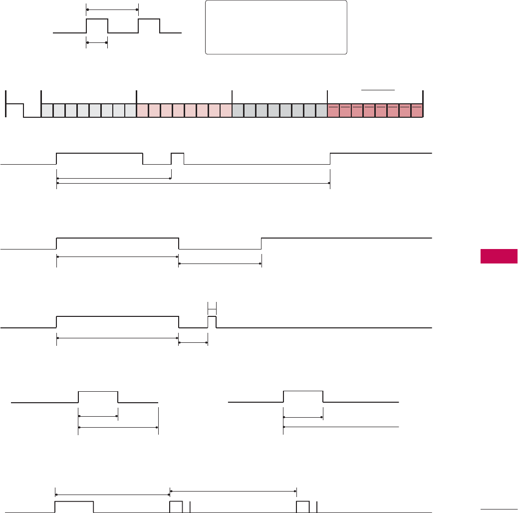
APPENDIX
119
IR CODES
■
Configuration of frame
1st frame
Repeat frame
■
Lead code
■
Repeat code
■Bit d
d
escription
■Frame i
i
nterval: T
T
f
The waveform is transmitted as long as a key is depressed.
C0 C1 C2 C3 C4 C5 C6 C7 C0 C1 C2 C3 C4 C5 C6 C7 D0 D1 D2 D3 D4 D5 D6 D7 D0 D1 D2 D3 D4 D5 D6 D7
Lead code Low custom code High custom code Data code Data code
Repeat code Tf
4.5 ms
9 ms
2.25 ms
9 ms
0.55 ms
0.56 ms
1.12 ms
0.56 ms
2.24 ms
Tf Tf
Tf=108ms @455KHz
Bit ”0” Bit ”1”
1. How to Connect
■Connect your wired remote control to the Remote Control port on the TV.
2. Remote Control IR Codes
■
Output waveform
Single pulse, modulated with 37.917KHz signal at 455KHz
T1
Tc
Carrier frequency
FCAR = 1/TC = fOSC/12
Duty ratio = T1/TC = 1/3

APPENDIX
120
APPENDIX
Code Function Note
(Hexa)
08 POWER
Remote control Button (Power On/Off)
45 Q.MENU Remote control Button
43 MENU Remote control Button
0B INPUT Remote control Button
10-19 Number Key 0-9 Remote control Button
4C - (Dash) Remote control Button
1A FLASHBK Remote control Button
09 MUTE Remote control Button
02 VOL + Remote control Button
03 VOL - Remote control Button
00 CH Remote control Button
01 CH Remote control Button
1E FAV Remote control Button
40 Remote control Button
41 Remote control Button
07 Remote control Button
06 Remote control Button
44 ENTER Remote control Button
5B RETURN Remote control Button
7E SIMPLINK Remote control Button
30 AV MODE Remote control Button
B0 PLAY Remote control Button
BA PAUSE Remote control Button
B1 STOP Remote control Button
BD REC Remote control Button
8F REW Remote control Button
8E FF Remote control Button
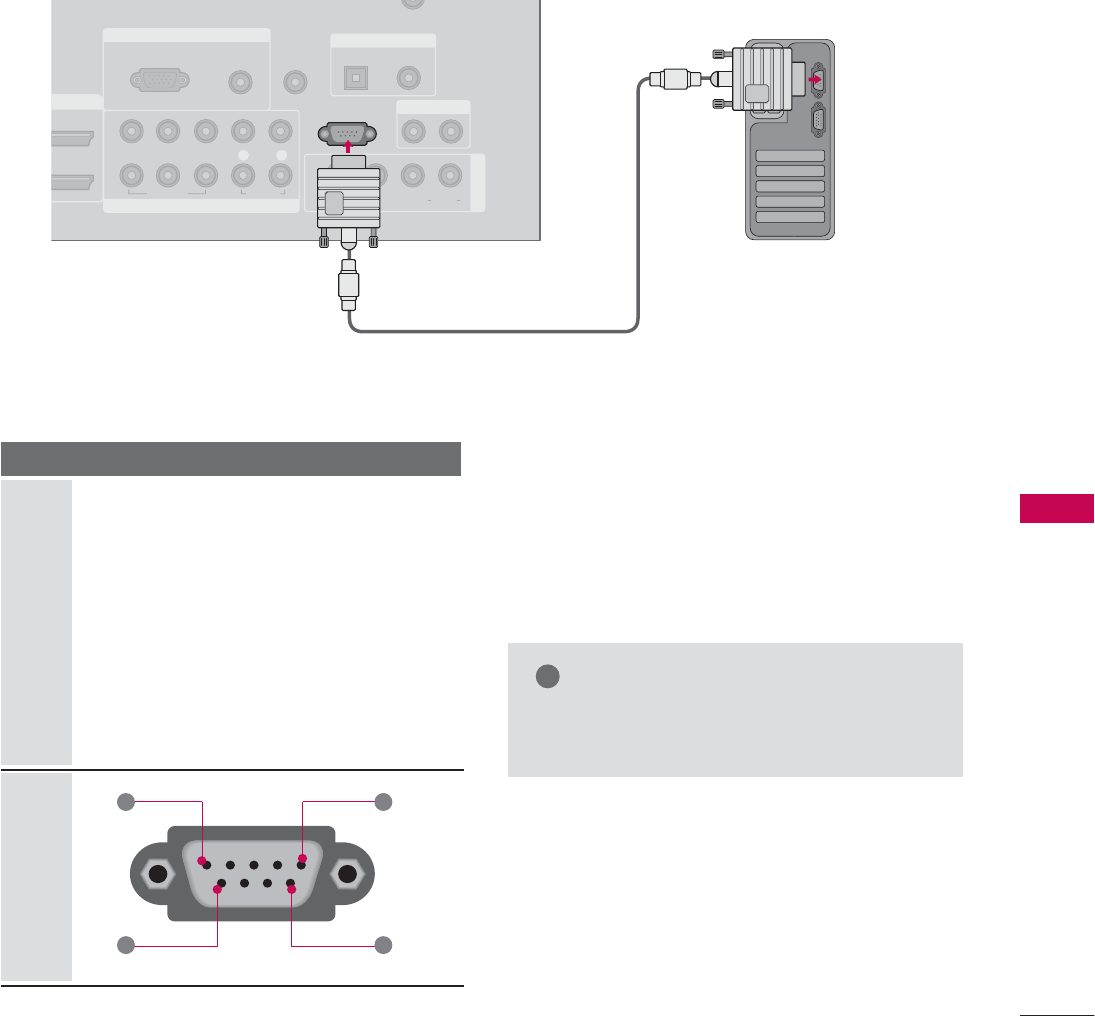
APPENDIX
121
EXTERNAL CONTROL THROUGH RS-232C
RS-232C Setup
The RS-232C port allows you connect the RS-232C input jack to an external control device (such as a computer
or an A/V control system) to control the TV’s functions externally.
■Note: RS-232C on this unit is intended to be used with third party RS-232C control hardware and software.
The instructions below are provided to help with programming software or to test functionality using telenet
software.
RGB IN
COMPONENT IN
AUDIO
(RGB/DVI)
RGB(PC)
REMOTE
CONTROL IN
CABLE IN
1
2
RS-232C IN
(CONTROL & SERVICE)
VIDEO
LYP
B
P
R
R
AUDIO
OPTICAL COAXIAL
DIGITAL AUDIO OUT
AUDIO OUT
AV IN 1
DVI IN
VIDEO L R
(MONO)
AUDIO
S-VIDEO
Type of Connector; D-Sub 9-Pin Male
No. Pin Name
1 No connection
2 RXD (Receive data)
3 TXD (Transmit data)
4 DTR (DTE side ready)
5 GND
6 DSR (DCE side ready)
7 RTS (Ready to send)
8 CTS (Clear to send)
9 No Connection
1
6
5
9
PC
Communication Parameters
■Baud rate : 9600 bps (UART)
■Data length : 8 bits
■Parity : None
■Stop bit : 1 bit
■Communication code : ASCII code
■Use a crossed (reverse) cable.
NOTE
!
GThis product has command echo back in the
RS-232C Command.
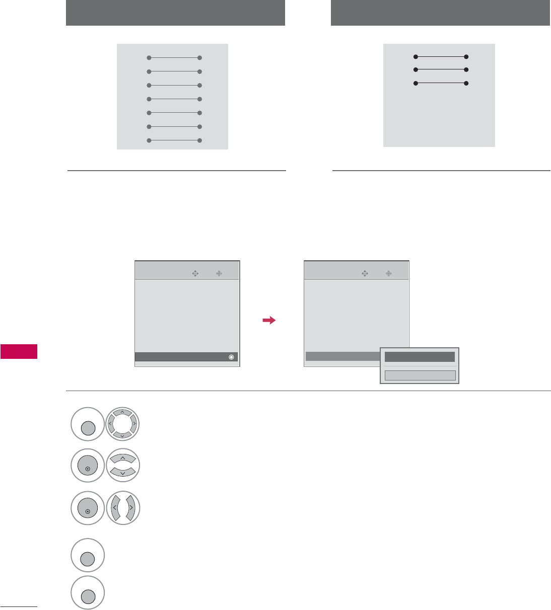
APPENDIX
122
RS-232C Configurations
APPENDIX
Use this function to specify a TV ID number.
Refer to ‘Real Data Mapping1’. Gp.125.
Either cable below can be used.
Set ID
PC TV
RXD 2 3 TXD
TXD 3 2 RXD
GND 5 5 GND
DTR 4 6 DSR
DSR 6 4 DTR
RTS 7 8 CTS
CTS 8 7 RTS
D-Sub 9 D-Sub 9
PC TV
RXD 2 3 TXD
TXD 3 2 RXD
GND 5 5 GND
DTR 4 6 DTR
DSR 6 4 DSR
RTS 7 7 RTS
CTS 8 8 CTS
D-Sub 9 D-Sub 9
7-Wire Configuration
(Serial female-female NULL modem cable)
3-Wire Configurations
(Not standard)
Enter
Move
OPTION
Enter
Move
OPTION
Language : English
Input Label
SIMPLINK : On
Key Lock : Off
Caption : Off
ISM Method
Power Saving : Level 0
Set ID : 1
Language : English
Input Label
SIMPLINK : On
Key Lock : Off
Caption : Off
ISM Method
Power Saving : Level 0
Set ID : 1
EE
Select OPTION.
Select Set I
I
D.
Choose the desired TV ID number.
The adjustment range of Set ID is
1~99.
1
MENU
3
2
ENTER
ENTER
F 1G
Close
4
RETURN
Return to the previous menu.
MENU
Return to TV viewing
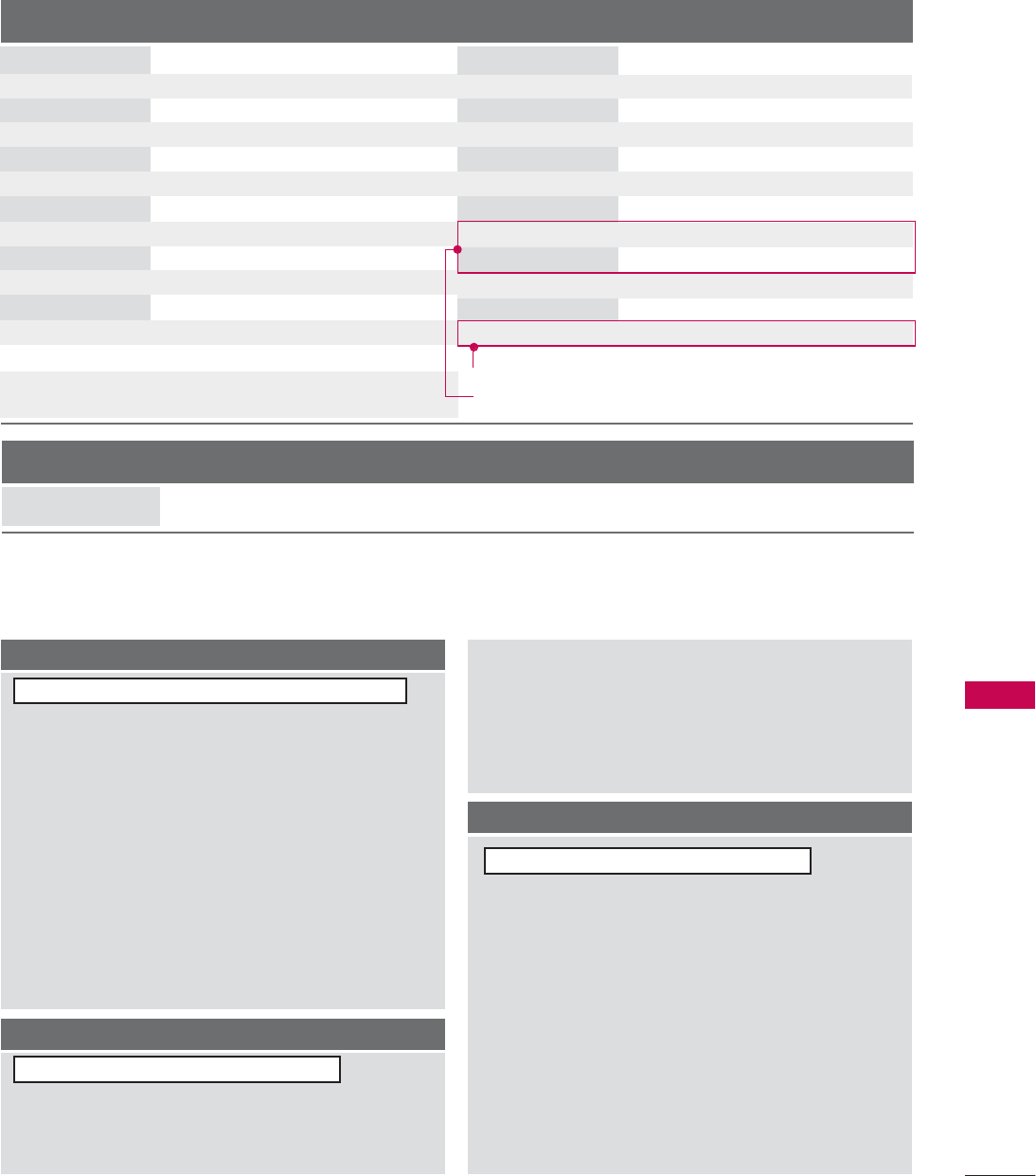
APPENDIX
123
Command Reference List
COMMAND1 COMMAND2
24. Channel Tuning
DATA
(Hexadecimal)
COMMAND1 COMMAND2
DATA
(Hexadecimal)
COMMAND1 COMMAND2
DATA0
(Hexadecimal)
DATA1
(Hexadecimal)
DATA2
(Hexadecimal)
DATA3
(Hexadecimal)
DATA4
(Hexadecimal)
DATA5
(Hexadecimal)
physical major major low minor high minor low attribute
program high program low
ma
01. Power k a 0 ~1
02. Input Select k b (Gp.124)
03. Input Select x b (Gp.124)
04. Aspect Ratio k c (Gp.124)
05. Screen Mute k d 0 ~1
06. Volume Mute k e 0 ~1
07. Volume Control k f 0 ~64
08. Contrast k g 0 ~64
09. Brightness k h 0 ~64
10. Color k i 0 ~64
11. Tint k j 0 ~64
12. Sharpness k k 0 ~64
13. OSD Select k l 0 ~1
14. Remote Control
Lock Mode
Transmission / Receiving Protocol
Transmission
[Command 1] : First command to control the set.(j, k, m or x)
[Command 2] : Second command to control the set.
[Set ID] : You can adjust the set ID to choose desired TV ID
number in Setup menu. Adjustment range is 1~99.
When selecting Set ID ‘0’, every connected the TV is
controlled. Set ID is indicated as decimal (1~99)on
menu and as Hexa decimal (0x0~0x63)on transmission
/receiving protocol.
[DATA] : To transmit the command data.
Transmit the ‘FF’ data to read status of command.
[Cr] : Carriage Return
ASCII code ‘0x0D’
[ ] : ASCII code ‘space (0x20)’
* In this model, TV will not send the status during the standby mode.
OK A
A
cknowledgement
The TV transmits ACK (acknowledgement) based on this for-
mat when receiving normal data. At this time, if the data is
data read mode, it indicates present status data. If the data is
data write mode, it returns the data of the PC computer.
* In this model, TV will not send the status during the standby mode.
* Data Format
[Command 2] : Use as command.
[Set ID] : Use the small character, if set ID is 10, it will send the ‘0’, ‘a’.
[DATA] : Use the small character, if data is 0 x ab, it will send the ‘a’, ‘b’.
[OK] : Use the large character.
Error A
A
cknowledgement
The TV transmits ACK (acknowledgement) based on this for-
mat when receiving abnormal data from non-viable functions
or communication errors.
Data1: Illegal Code
Data2: Not supported function
Data3: Wait more time
* In this model, TV will not send the status during the standby mode.
* Data Format
[Command 2] : Use as command.
[Set ID] : Use the small character, if set ID is 10, it will send the ‘0’, ‘a’.
[DATA] : Use the small character, if data is 0 x ab, it will send the ‘a’, ‘b’.
[NG] : Use the large character
[Command1][Command2][ ]
]
[Set I
I
D][ ]
]
[Data][Cr]
[Command2][ ]
]
[Set I
I
D][ ]
]
[OK][Data][x]
[Command2][ ]
]
[Set I
I
D][ ]
]
[NG][Data][x]
15. Treble k r 0 ~64
16. Bass k s 0 ~64
17. Balance k t 0 ~64
18 .
Color Temperature
k u 0 ~3
19. Red Adjustment k v 0 ~C8
20. Green Adjustment k w 0 ~C8
21. Blue Adjustment k $ 0 ~C8
22. ISM Method j p (Gp.126)
23. Low Power j q 0 ~1
25. Channel Add/Del m b 0 ~1
26. Key m c (Gp.127)
27. Back Light m g 0 ~64
0 ~1
k m Only Plasma TV Model
Only LCD TV Model

APPENDIX
124
APPENDIX
01. Power (
(
Command: k
k
a
a
)
To control Power On/Off of the TV.
Transmission [k][a][ ][Set ID][ ][Data][Cr]
Data 0: Power Off Data 1: Power On
Acknowledgement [a][ ][Set ID][ ][OK/NG][Data][x]
* In a like manner, if other functions transmit ‘FF’ data
based on this format, Acknowledgement data feedback
presents status about each function.
* Note: In this model, TV will send the Acknowledge
after power on processing completion.
There might be a time delay between command and
acknowledge.
02. I
I
nput S
S
elect (
(
Command: k
k
b
b
)
To select input source for the TV.
Transmission [k][b][ ][Set ID][ ][Data][Cr]
Data 0: DTV Data 1: Analog
Data 2: AV1 Data 3: AV2
Data 4: Component 1 Data 5: Component 2
Data 7: RGB-PC Data 8: HDMI1
Data 9: HDMI2
Acknowledgement [b][ ][Set ID][ ][OK/NG][Data][x]
* You can select HDMI3 using “command x
x
b
b
”.
* If you select input source, we recommend “command x
x
b
b
”.
03. I
I
nput S
S
elect (
(
Command: x
x
b
b
)
To select input source for TV.
Transmission [x][b][ ][Set ID][ ][Data][Cr]
Data 00: DTV (Antenna) Data 01: DTV (Cable)
Data 10: Analog (Antenna) Data 11: Analog (Cable)
Data 20: AV1 Data 21: AV2
Data 40: Component 1 Data 41: Component 2
Data 60: RGB-PC Data 90: HDMI1
Data 91: HDMI2 Data 92: HDMI3
Acknowledgement [b][ ][Set ID][ ][OK/NG][Data][x]
04. A
A
spect R
R
atio (
(
Command: k
k
c
c
)
To adjust the screen format.
You can also adjust the screen format using the RATIO
button on remote control or in the Picture menu.
Transmission [k][c][ ][Set ID][ ][Data][Cr]
Data 1: 4:3 5: Zoom 2
2: 16:9 6: Set by program
4: Zoom 1 9: Just scan
Reserved
Acknowledgement [c][ ][Set ID][ ][OK/NG][Data][x]
05. Screen M
M
ute (
(
Command: k
k
d
d
)
To select screen mute on/off.
Transmission [k][d][ ][Set ID][ ][Data][Cr]
Data 0: Screen mute off (Picture on)
Data 1: Screen mute on (Picture off)
Acknowledgement [d][ ][Set ID][ ][OK/NG][Data][x]
06. V
V
olume M
M
ute (
(
Command: k
k
e
e
)
To control volume mute on/off.
You can also adjust mute using the MUTE button on
remote control.
Transmission [k][e][ ][Set ID][ ][Data][Cr]
Data 0 : Volume mute on (Volume off)
Data 1 : Volume mute off (Volume on)
Acknowledgement [e][ ][Set ID][ ][OK/NG][Data][x]
07. V
V
olume C
C
ontrol (
(
Command: k
k
f
f
)
To adjust volume.
You can also adjust volume with the volume buttons on
remote control.
Transmission [k][f][ ][Set ID][ ][Data][Cr]
Data Min : 0 ~Max : 64 (*transmit by Hexadecimal code)
*Refer to ‘Real data mapping 1’. See page 125.
Acknowledgement [f][ ][Set ID][ ][OK/NG][Data][x]
08. C
C
ontrast (
(
Command: k
k
g
g
)
To adjust screen contrast.
You can also adjust contrast in the Picture menu.
Transmission [k][g][ ][Set ID][ ][Data][Cr]
Data Min : 0 ~Max : 64 (*transmit by Hexadecimal code)
*Refer to ‘Real data mapping 1’. See page 125.
Acknowledgement [g][ ][Set ID][ ][OK/NG][Data][x]
09. B
B
rightness (
(
Command: k
k
h
h
)
To adjust screen brightness.
You can also adjust brightness in the Picture menu.
Transmission [k][h][ ][Set ID][ ][Data][Cr]
Data Min : 0 ~Max : 64 (*transmit by Hexadecimal code)
*Refer to ‘Real data mapping 1’. See page 125.
Acknowledgement [h][ ][Set ID][ ][OK/NG][Data][x]

APPENDIX
125
10. C
C
olor (
(
Command: k
k
i
i
)
To adjust screen color.
You can also adjust color in the Picture menu.
Transmission [k][i][ ][Set ID][ ][Data][Cr]
Data Min : 0 ~Max : 64 (*transmit by Hexadecimal code)
*Refer to ‘Real data mapping 1’ as shown below.
Acknowledgement [i][ ][Set ID][ ][OK/NG][Data][x]
11. T
T
int (
(
Command: k
k
j
j
)
To adjust screen tint.
You can also adjust tint in the Picture menu.
Transmission [k][j][ ][Set ID][ ][Data][Cr]
Data Red: 0 ~Green: 64 (*transmit by Hexadecimal code)
*Refer to ‘Real data mapping 1’ as shown below.
Acknowledgement [ j ][ ][Set ID][ ][OK/NG][Data][x]
12. S
S
harpness (
(
Command: k
k
k
k
)
To adjust screen sharpness.
You can also adjust sharpness in the Picture menu.
Transmission [k][k][ ][Set ID][ ][Data][Cr]
Data Min : 0 ~Max : 64 (*transmit by Hexadecimal code)
*Refer to ‘Real data mapping 1’ as shown below.
Acknowledgement [k][ ][Set ID][ ][OK/NG][Data][x]
13. O
O
SD S
S
elect (
(
Command: k
k
l
l
)
To select OSD (On Screen Display) on/off.
Transmission [k][l][ ][Set ID][ ][Data][Cr]
Data 0: OSD off Data 1: OSD on
Acknowledgement [l][ ][Set ID][ ][OK/NG][Data][x]
14. R
R
emote C
C
ontrol L
L
ock M
M
ode (
(
Command: k
k
m
m
)
To lock the remote control and the front panel controls
on the set.
Transmission [k][m][ ][Set ID][ ][Data][Cr]
Data 0: Lock off Data 1: Lock on
Acknowledgement [m][ ][Set ID][ ][OK/NG][Data][x]
If you’re not using the remote control and front panel
controls on the TV, use this mode. When main power is
on/off, remote control lock is released.
15. T
T
reble (
(
Command: k
k
r
r
)
To adjust treble.
You can also adjust treble in the Audio menu.
Transmission [k][r][ ][Set ID][ ][Data][Cr]
Data Min: 0 ~Max: 64 (*transmit by Hexadecimal code)
*Refer to ‘Real data mapping 1’ as shown.
Acknowledgement [r][ ][Set ID][ ][OK/NG][Data][x]
16. Bass (
(
Command: k
k
s
s
)
To adjust bass.
You can also adjust bass in the Audio menu.
Transmission [k][s][ ][Set ID][ ][Data][Cr]
Data Min: 0 ~Max: 64 (*transmit by Hexadecimal code)
*Refer to ‘Real data mapping 1’ as shown below.
Acknowledgement [s][ ][Set ID][ ][OK/NG][Data][x]
17. B
B
alance (
(
Command: k
k
t
t
)
To adjust balance.
You can also adjust balance in the Audio menu.
Transmission [k][t][ ][Set ID][ ][Data][Cr]
Data Min: 0 ~Max: 64 (*transmit by Hexadecimal code)
*Refer to ‘Real data mapping 1’ as shown below.
Acknowledgement [t][ ][Set ID][ ][OK/NG][Data][x]
18. C
C
olor T
T
emperature (
(
Command: k
k
u
u
)
To adjust color temperature.
You can also adjust color temperature in the Picture menu.
Transmission [k][u][ ][Set ID][ ][Data][Cr]
Data 0: Medium 1: Cool 2: Warm 3: User
Acknowledgement [u][ ][Set ID][ ][OK/NG][Data][x]
19. R
R
ed A
A
djustment (
(
Command: k
k
v
v
)
To adjust red in color temperature
Transmission [k][v][ ][Set ID][ ][Data][Cr]
Data Min: 0 ~Max: C8
*Refer to ‘Real data mapping 2’ as shown below.
Acknowledgement [v][ ][Set ID][ ][OK/NG][Data][x]
20. G
G
reen A
A
djustment (
(
Command: k
k
w
w
)
To adjust green in color temperature.
Transmission [k][w][ ][Set ID][ ][Data][Cr]
Data Min: 0 ~Max: C8
*Refer to ‘Real data mapping 2’ as shown below.
Acknowledgement [w][ ][Set ID][ ][OK/NG][Data][x]
*Real data mapping 1
0 : Step 0
A : Step 10 (SET ID 10)
F : Step 15 (SET ID 15)
10 : Step 16 (SET ID 16)
63 : Step 99 (SET ID 99)
64 : Step 100
*Real data mapping 2
0 : -20
5 : -19
A : -18
5F: -1
64: 0
69: +1
C3 : +19
C8 : +20

APPENDIX
126
APPENDIX
21. B
B
lue A
A
djustment (
(
Command: k
k
$
$
)
To adjust blue in color temperature.
Transmission [k][$][ ][Set ID][ ][Data][Cr]
Data Min: 0 ~Max: C8
*Refer to ‘Real data mapping 2’. See page 125.
Acknowledgement [$][ ][Set ID][ ][OK/NG][Data][x]]
22. I
I
SM M
M
ethod (
(
Command2: j
j
p
p
)
(Only Plasma TV model)
To avoid having a fixed image remain on screen.
Transmission [ j ][p][ ][Set ID][ ][Data][Cr]
Data 1: Inversion 2: Orbiter
4: White Wash 8: Normal
Acknowledgement [p][ ][Set ID][ ][OK/NG][Data][x]
23. L
L
ow P
P
ower (
(
Command2: j
j
q
q
)
(Only Plasma TV model)
To control the low power function on/off.
Transmission [ j ][q][ ][Set ID][ ][Data][Cr]
Data 0: Low Power off
1: Low Power on
Acknowledgement [q][ ][Set ID][ ][OK/NG][Data][x]
24. C
C
hannel T
T
uning (
(
Command: m
m
a
a
)
To tune channel to following physical/major/minor number.
Transmission [m][a][ ][Set ID][ ][Data0][ ][Data1]
[ ][Data2][ ][Data3][ ][Data4][ ][Data5][Cr]
Digital channels have a Physical, Major, and Minor channel
number. The Physical number is the actual digital channel
number, the Major is the number that the channel should
be mapped to, and the Minor is the sub-channel. Since
the ATSC tuner automatically maps the channel to the
Major number, the Physical number is not required when
sending a command.
Data 0: Physical Channel Number
NTSC air: 02~45, NTSC cable: 01, 0E~7D
ATSC air: 01~45, ATSC cable: 01~87
Data1 & 2: Major Channel Number
Data1: High byte Data2: Low byte
Two bytes are available for the Major and Minor, nor-
mally only the second byte is used.
Data3 & 4: Minor Channel Number
Not needed for NTSC.

APPENDIX
127
Data5:
The table above lists the binary code which must be
converted to Hexadecimal before sending. For example:
The binary code to tune the sub source to an NTSC
cable channel is “1000 0001”, which translates to “81”
in Hex.
* 7th bit : For which source do you want to change the
channel.
* 6th bit: Use a two part or one part channel. Most cases
just use 0 since it’s ignored when using NTSC.
* 5th bit: Use 0 with NTSC since it can only use the phys-
ical channel number. Normally use 1 for ATSC since most
times it doesn’t matter what the physical number is.
* 4th bit: Set to 0.
* 3-0 bits: Choose signal type.
* Tune Command Examples:
1. Tune to the analog (NTSC) cable channel 35.
Data 0 = Physical of 35 = 23
Data 1 & 2 = No Major = 00 00
Data 3 & 4 = No Minor = 00 00
Data 5 = 0000 0001 in binary = 01
Total = ma 00 23 00 00 00 00 01
2. Tune to the digital (ATSC) local channel 30-3.
Data 0 = Don’t know Physical = 00
Data 1 & 2 = Major is 30 = 00 1E
Data 3 & 4 = Minor is 3 = 00 03
Data 5 = 0010 0010 in binary = 22
Total = ma 00 00 00 1E 00 03 22
Acknowledgement[a][ ][Set ID][ ][OK][Data0][Data1]
[Data2][Data3][Data4][x][a][ ][Set ID]
[ ][NG][Data0][x]
25. C
C
hannel A
A
dd/Del (
(
Command: m
m
b
b
)
To add and delete the channels
Transmission [m][b][ ][Set ID][ ][Data][Cr]
Data 0: Channel Delete Data 1: Channel Add
Acknowledgement [b][ ][Set ID][ ][OK/NG][Data][x]
26. K
K
ey (
(
Command: m
m
c
c
)
To send IR remote key code.
Transmission [m][c][ ][Set ID][ ][Data][Cr]
Data Key code: Refer to page 120.
Acknowledgement [c][ ][Set ID][ ][OK/NG][Data][x]
27. B
B
ack L
L
ight (
(
Command: m
m
g
g
)
(Only LCD TV model)
To adjust screen back light.
Transmission [m][g][ ][Set ID][ ][Data][Cr]
Data Min:0 ~Max:64 (*transmit by Hexadecimal code)
*Refer to ‘Real data mapping 1’. See page 125.
Acknowledgement [g][ ][Set ID][ ][OK/NG][Data][x]
Step
NTSC Air
NTSC Cable
ATSC Air
ATSC Cable_std
ATSC Cable_hrc
ATSC Cable_irc
ATSC cable_auto
Reserved
...
Reserved
1
0
0
1
1
0
0
1
1
x
1
2
0
0
0
0
1
1
1
1
x
1
3
0
0
0
0
0
0
0
0
x
1
4
x
x
x
x
x
x
x
x
x
x
Reserved
5
0
1
Use
No Use
Using Physical
Channel
6
0
1
Two
One
Two/One
Part Channel
7
0
1
Main
Sub
Main/Sub
Picture 0
0
1
0
1
0
1
0
1
x
1


Regulatory information
Regulatory information
Regulatory Information cont.
FCC Compliance Statement
This equipment has been tested and found to comply
within the limits of a Class B digital device pursuant to Part
15 of the FCC Rules. These limits are designed to provide
reasonable protection against harmful interference in a
residential installation.
This equipment generates, uses, and can radiate radio
frequency energy and if not installed and used in
accordance with the instructions, may cause harmful
interference to radio communications. However, there is
no guarantee that interference will not occur in a particular
installation.
If this equipment does cause harmful interference to radio
or television reception (which can be determined by
turning the equipment on and off), the user is encouraged
to try to correct the interference by using one or more of
the following measures:
Reorient or relocate the receiving antenna.
Increase the separation between the equipment and
the receiver.
Connect the equipment into an outlet on a circuit
different from that to which the receiver is connected.
Consult the dealer or an experienced radio/TV
technician for help.
Caution: Changes or modifications not expressly approved
by the party responsible for compliance could void the
user's (or your) authority to operate the equipment. Only
peripherals (digital input/output devices, terminals, printers,
etc.) certified to comply with the Class B limits may be
attached to this monitor. Operation with non-certified
peripherals is likely to result in interference to radio and TV
reception. Only shielded signal cables may be used with
this System.
Canadian DOC Notice
This Class B digital apparatus meets all requirements of
the Canadian Interference-Causing Equipment
Regulations. Cet appareil numérique de la classe B
respecte toutes les exigences du Règlement sur le
matériel brouilleur du Canada.
CE Conformity Notice
(for Europe)
Products with the “CE” Marking comply with the EMC
Directive(89/336/EEC) and LOW VOLTAGE Directive
(73/23/EEC) issued by the Commission of the European
Community.
Compiance with these directives implies conformity to the
following European Norms :
• EN 55022 ; Radio Frequency Interference
• EN 55024 ; Electromagnetic Immunity
• EN 61000-3-2 ; Power Line Harmonics
•EN 61000-3-3 ; Voltage Fluctuations
• EN 60950 ; Product Safety
Low Radiation Compliance (MPR II)
This monitor meets one of the strictest guidelines available
today for low radiation emissions, offering the user extra
shielding and an antistatic screen coating. These
guidelines, set forth by a government agency in Sweden,
limit the amount of emission allowed in the Extremely Low
Frequency (ELF) and Very Low Frequency (VLF)
electromagnetic range.
TCO95 (TCO95 applied model only)
Congratulations!
You have just purchased a TCO’95 approved and labelled
product! Your choice has provided you with a product
developed for professional use. Your purchase has also
contributed to reducing the burden on the environment and
to the further development of environmentally-adapted
electronic products.
01
NOTICE
The regulations are applied only to the products with the
ID LABEL indicating specific requirements.
NOTICE
The regulations are applied only to the products with the
ID LABEL indicating specific requirements.
NOTICE
The regulations are applied only to the products with the
ID LABEL indicating specific requirements.
Regulatory Information cont.
02
Why do we have environmentally labelled computers?
In many countries, environmental labelling has become an
established method for encouraging the adaptation of
goods and services to the environment. The main problem
as far as computers and other electronic equipment are
concerned is that environmentally harmful substances are
used both in the products and during their manufacture.
Since it has not been possible so far for the majority of
electronic equipment to be recycled in a satisfactory way,
most of these potentially damaging substances sooner or
later enter Nature.
There are also other characteristics of a computer, such as
energy consumption levels, that are important from both
the working and natural environment viewpoints. Since all
types of conventional electricity generation have a
negative effect on the environment (acidic- and climatic-
influencing emissions, radioactive waste, etc.), it is vital to
conserve energy. Electronic equipment in offices
consumes as enormous amount of energy, since it is often
routinely left running continuously.
What does the environmenal labelling involve?
This product meets the requirements for the TCO’95
scheme, which provides for international environmental
labelling of personal computers. The labelling scheme was
developed as a joint effort by the TCO (The Swedish
Confederation of Professional Employees),
Naturckyddsföreningen (The Swedish Society for Nature
Conservation), and NUTEK (The National Board for
Industrial and Technical Development in Sweden), and
SEMKO AB (an international certification agency).
The requirements cover a wide range of issues:
environment, ergonomics, usability, emission of electrical
and magnetic fields, energy consumption and electrical
and fire safety.
The environmental demands concern, among other things,
restriction on the presence and use of heavy metals,
brominated and chlorinated flame retardants, CFCs
(freons), and chlorinated solvents. The product must be
prepared for recycling, and the manufacturer is obliged to
have an environmental plan, which must be adhered to in
each country where the company implements its
operational policy.
The energy requirements include a demand that the
computer and/or display, after a certain period of inactivity,
shall reduce its power consumption to a lower level, in one
or more stages. The length of time to reactivate the
computer shall be reasonable for the user.
Labelled products must meet strict environmental
demands, for example, in respect of the reduction of
electric and magnetic fields, along with physical and visual
ergonomics and good usability.
The following is a brief summary of the environmental
requirements met by this product. The complete
environmental criteria document may be ordered from:
TCO Development Unit
Linnegatan 14, S-11494 Stockholm, Sweden
FAX +46-8 782 92 07
E-mail (Internet): development@tco.se
Current information regarding TCO’95 approved and
labelled products may also be obtained on the Internet
using the address: http://www.tco-info.com/
TCO’95 is a co-operative project between:
Environmental requirements
Brominated flame retardants are present in printed circuit
boards, cabling, casings, and housings, and are added to
delay the spread of fire. Up to 30% of the plastic in a
computer casing can consist of flame-retardant
substances. These are related to another group of
environmental toxins, PCBs, and are suspected of giving
rise to similar harm, including reproductive damage in fish-
eating birds and mammals. Flame retardants have been
found in human blood, and researchers fear that they can
disturb fetus development.
Bio-accumulative1TCO’95 demands require that plastic
components weighing more than 25 grams must not
contain flame retardants with organically bound chlorine or
bromine.
Lead can be found in picture tubes, display screens,
solder, and capacitors. Lead damages the nervous
system and in higher doses causes lead poisoning. The
NUTEK
Naturskydds
föreningen
Närings- och teknikutvecklingsverket
SEMKO
Regulatory Information cont.
03
relevant bio-accumulative TCO’95 requirement permits
the inclusion of lead, as no replacement has yet been
developed.
Cadmium is present in rechargeable batteries and in the
color-generating layers of certain computer displays.
Cadmium damages the nervous system and is toxic in
high doses. The relevant bio-accumulative TCO’95
requirement states that batteries may not contain more
than 25 ppm (parts per million) of cadmium. The color-
generating layers of display screens must not contain any
cadmium.
Mercury is sometimes found in batteries, relays and
switches. Mercury damages the nervous system and is
toxic in high doses. The relevant bio-accumulative TCO’95
requirement states that batteries may not contain more
than 25 ppm of mercury and that no mercury is present in
any of the electrical or electronic components concerned
with the display unit.
CFCs (freons) are sometimes used for washing printed
circuit boards and in the manufacture of expanded foam
for packaging. CFCs break down ozone and thereby
damage the ozone layer in the atmosphere, causing
increased reception on Earth of ultra-violet light with
consequent increased risks of skin cancer (malignant
melanoma). The relevant TCO’95 requirement: Neither
CFCs nor HCFCs may be used during the manufacture of
the product or its packaging.
1Bio-accumulative means that the substance accumulates
within living organisms.
Shipping Package
The packaging material can be recycled, or you can save
it to return the monitor to a service center for repair or
disposal.
CFC Compounds in Distribution Packaging
Cushioning material used for shipping finished monitors
are not manufactured with nor do they contain any CFC
compounds.
Design for Disassembly/Recycling
These monitors have been designed for easy end-of-life
disassembly and recycling. Fasteners are generally of the
same type for efficient disassembly. Components made of
different materials can be easily separated and plastics
have been identified using intermational symbols to aid in
recycling.
Monitor Disposal
TCO'99 (TCO'99 applied model only)
Congratulations!
You have just purchased a TCO’99 approved and labelled
product! Your choice has provided you with a product
developed for professional use. Your purchase has also
contributed to reducing the burden on the environment and
also to the further development of environmentally
adapted electronics products.
Why do we have environmentally labelled computers?
In many countries, environmental labelling has become an
established method for encouraging the adaptation of
goods and services to the environment. With the growing
manufacture and usage of electronic equipment
throughout the world, there is a recognized concern for the
materials and substances used by electronic products
with regards to their eventual recycling and disposal. By
proper selection of these materials and substances, the
impact on the environment can be minimized.
There are also other characteristics of a computer, such as
energy consumption levels, that are important from the
viewpoints of both the work (internal) and natural (external)
environments. Electronic equipment in offices is often left
running continuously, resulting in unnecessary
consumption of large amounts of energy and additional
power generation. From the standpoint of carbon dioxide
emissions alone, it is vital to save energy.
What does labelling involve?
The product meets the requirements for the TCO’99
scheme which provides for international and environmental
labelling of personal computers and/or displays.
The labelling scheme was developed as a joint effort by the
TCO (The Swedish Confederation of Professional
Employees), Svenska Naturskyddsforeningen
(The Swedish Society for Nature Conservation) and
Statens Energimyndighet (The Swedish National
Energy Administration).
WARNING
If you need to dispose of a monitor, ask a qualified service
representative for the proper procedure. Improper disposal could
result in personal injury from implosion.
Regulatory Information cont.
04
Approval requirements cover a wide range of issues:
ecology, ergonomics, emission of electrical and
magnetical fields, energy consumption and electrical
safety.
Ecological criteria impose restrictions on the presence and
use of heavy metals, brominated and chlorinated flame
retardants, and other substances. The product must be
prepared for recycling and the manufacturing site(s) shall
be certified according to ISO14001 or EMAS registered.
Energy requirements include a demand that the system
unit and/or display, after a certain period of inactivity,
shall reduce its power consumption to a lower level in one
or more stages. The length of time to reactivate the system
unit shall be reasonable for the user.
Labelled products must meet strict environmental
demands, for example, in respect of the reduction of
electrical and magnetical fields as well as work load and
visual ergonomics.
Below you will find a brief summary of the ecological
requirements met by this product. The complete
ecological criteria document can be found at TCO
Development’s website http://www.tcodevelopment.com or
may be ordered from:
TCO Development
SE-114 94 STOCKHOLM, Sweden
Fax: +46 8 782 92 07
Email : development@tco.se
Information regarding TCO’99 approved and labelled
products may also be obtained at
http://www.tcodevelopment.com
Ecological requirements
Flame retardants
Flame retardants may be present in printed wiring board
laminates, cables, and housings. Their purpose is to
prevent, or at least to delay the spread of fire. Up to 30%
by weight of the plastic in a computer casing can consist of
flame retardant substances. Many flame retardants
contain bromine or chlorine, and these flame retardants
are chemically related to PCBs (polychlorinated
biphenyls). Both the flame retardants containing bromine
or chlorine and the PCBs are suspected of giving rise to
health effects, including reproductive damage in fish-eating
birds and mammals, due to the bio-accumulative*
processes when not disposed of in accordance with strict
standards for disposal.
TCO’99 requires that plastic components weighing more
than 25 grams shall not contain flame retardants with
organically bound bromine or chlorine. Flame retardants
are allowed in the printed wiring board laminates due to
the lack of commercially available alternatives.
Cadmium**
Cadmium is present in rechargeable batteries and in the
colour-generating layers of certain computer displays.
TCO’99 requires that batteries, the colour-generating
layers of display screens, and the electrical or electronics
components shall not contain any cadmium.
Mercury**
Mercury is sometimes found in batteries, relays and
switches. TCO’99 requires that batteries shall not contain
any mercury. It also demands that mercury is not present
in any of the electrical or electronics components
associated with the labelled unit. There is however one
exception. Mercury is, for the time being, permitted in the
back light system of flat panel monitors as there today is
no commercially available alternative. TCO aims on
removing this exception when a mercury free alternative is
available.
Lead**
Lead can be found in picture tubes, display screens,
solders and capacitors. TCO’99 permits the use of lead
due to the lack of commercially available alternatives, but
in future requirements TCO Development aims at
restricting the use of lead.
_____________________________________________
* Bio-accumulative is defined as substances which
accumulate in living organisms.
**Lead, Cadmium and Mercury are heavy metals
which are bio-accumulative.
05
Regulatory Information cont.
TCO’03
(TCO’03 applied model only)
Congratulations!
The display you have just purchased carries the TCO’03
Displays label.
This means that your display is designed,manufactured
and tested according to some of the strictest quality and
environmental requirements in the world. This makes for a
high performance product, designed with the user in focus
that also minimizes the impact on our natural environment.
Some of the features of the TCO’03 Display requirements:
Ergonomics
• Good visual ergonomics and image quality in order to
improve the working environment for the user and to
reduce sight and strain problems. Important
parameters are luminance, contrast, resolution,
reflectance, colour rendition and image stability.
Energy
• Energy-saving mode after a certain time – beneficial
both for the user and the environment
• Electrical safety
Emissions
• Electromagnetic fields
• Noise emissions
Ecology
• The product must be prepared for recycling and the
manufacturer must have a certified environmental
management system such as EMAS or ISO 14 001
• Restrictions on
chlorinated and brominated flame retardants and
polymers
heavy metals such as cadmium, mercury and lead.
The requirements included in this label have been
developed by TCO Development in co-operation with
scientists, experts, users as well as manufacturers all over
the world. Since the end of the 1980s TCO has been
involved in influencing the development of IT equipment in
a more user-friendly direction. Our labelling system started
with displays in 1992 and is now requested by users and
IT-manufacturers all over the world.
For more information, please visit
www.tcodevelopment.com
Information for Environmental Preservation
LGE. announced the 'LG Declaration for a Cleaner
Environment' in 1994, and this ideal has served as a
guiding managerial principle ever since. The Declaration is
a foundation that has allowed us to undertake
environmentally friendly activities in careful consideration
of economic, environmental, and social aspects.
We promote activities for environmental preservation, and
we specifically develop our products to embrace the
concept of environment-friendly.
We minimize the hazardous materials contained in our
products. For example, there is no cadmium to be found in
our monitors.
Information for recycling
This monitor may contain parts which could be hazardous
to the environment. It is important that this monitor be
recycled after use.
LGE. handles all waste monitors through an
environmentally acceptable recycling method. There are
several take-back and recycling systems currently in
operation worldwide. Many parts will be reused and
recycled, while harmful substances and heavy metals are
treated by an environmentally friendly method.
If you want to find out more information about our recycling
program, please contact your local LG vendor or a
corporate representative of LG.
We set our vision and policies on a cleaner world by
selecting the issue of the global environment as a task for
corporate improvement. Please visit our website for more
information about our ‘green’ policies.
http://www.lge.com/experience/social_commitment/enviro
ment.jsp
English
06
Regulatory Information cont.
Informationen zur Erhaltung der Umwelt
Im Jahr 1994 verkündete LGE die 'LG Declaration for a
Cleaner Environment' (LG Erklärung für eine sauberere
Umwelt). Seitdem dient dieses Ideal als führendes Prinzip
des Unternehmens. Diese Erklärung war die Basis für die
Durchführung von
umweltfreundlichen Aktivitäten, wobei wirtschaftliche,
umweltbezogene und soziale Aspekte in die
Überlegungen mit einbezogen wurden.
Wir fördern Aktivitäten zum Schutz der Umwelt und die
Entwicklung unserer Produkte ist darauf ausgerichtet,
unserem Konzept bezüglich Umweltfreundlichkeit gerecht
zu werden.
Wir sind darauf bedacht, den Anteil der in unseren
Produkten enthaltenen schädlichen Materialien zu
minimieren. So ist in unseren Monitoren beispielsweise
kein Kadmium zu finden.
Informationen zum Thema Recycling
Dieser Monitor enthält Teile, die umweltschädlich sein
können. Es ist unbedingt erforderlich, dass der Monitor
recycelt wird, nachdem er außer Dienst gestellt wurde.
Bei LGE. werden alle ausrangierten Monitore in einem
unter umweltbezogenen Aspekten geeigneten Verfahren
recycelt. Augenblicklich sind weltweit mehrere
Rücknahme- und Recyclingsysteme im Einsatz. Viele
Teile werden wieder verwendet und recycelt. Schädliche
Substanzen und Schwermetalle werden durch
umweltverträgliche Verfahren behandelt.
Falls Sie mehr über unser Recyclingprogramm erfahren
möchten, wenden Sie sich bitte an Ihren lokalen LG-
Händler oder einen Unternehmensvertreter von LG.
Wir richten unsere Firmenpolitik auf eine sauberere
Umwelt hin aus, indem wir umweltspezifische Aspekte als
wichtigen Punkt in die Weiterentwicklung unseres
Unternehmens einfließen lassen. Zusätzliche
Informationen über unsere ‘grüne’ Firmenpolitik erhalten
Sie auf unserer Website.
http://www.lge.com/experience/social_commitment/enviro
ment.jsp
Information sur la protection de l’environnement
LGE. a publié sa 'Déclaration en faveur d’un
environnement plus propre' en 1994 et celle-ci est restée,
depuis lors, un principe directeur de notre entreprise. Cette
déclaration a servi de base à notre réflexion et nous a
permis de prendre en compte à la fois les aspects
économiques et sociaux de nos activités, tout en
respectant l’environnement.
Nous encourageons les activités en faveur de la
préservation de l’environnement et c’est dans cet esprit
que nous développons nos produits : nous réduisons au
minimum les matières dangereuses qui entrent dans leur
composition et l’on ne trouve pas de cadmium, par
exemple, dans nos moniteurs.
Information sur le recyclage
Ce moniteur peut contenir des composants qui présentent
un risque pour l’environnement. Il est donc important que
celui-ci soit recyclé après usage.
LGE. traite les moniteurs en fin de cycle conformément à
une méthode de recyclage respectueuse de
l’environnement. Nous reprenons nos produits et les
recyclons dans plusieurs sites répartis dans le monde
entier. De nombreux composants sont réutilisés et
recyclés, et les matières dangereuses, ainsi que les
métaux lourds, sont traités selon un procédé écologique.
Si vous souhaitez plus de renseignements sur notre
programme de recyclage, veuillez contacter votre
revendeur LG ou un l’un de nos représentants.
Nous voulons agir pour un monde plus propre et croyons
au rôle de notre entreprise dans l’amélioration de
l’environnement. Pour plus de renseignements sur notre
politique “verte”, rendez visite à notre site :
http://www.lge.com/experience/social_commitment/enviro
ment.jsp
Informazioni per la tutela dell’ambiente
La LGE. ha annunciato nel 1994 la cosiddetta 'LG
Declaration for a Cleaner Environment' (Dichiarazione di
LG a favore di un ambiente più pulito), un ideale che da
allora funge da principio ispiratore della gestione
aziendale. La dichiarazione rappresenta il fondamento che
consente di intraprendere attività a favore dell'ambiente
tenendo conto degli aspetti economici, ambientali e sociali.
Deutsch
Français
Italiano
07
Espanõl
Regulatory Information cont.
Noi della LG, promuoviamo attività a favore della tutela
dell'ambiente sviluppando appositamente i nostri prodotti
per cogliere il concetto del rispetto dell’ambiente riducendo
i materiali dannosi presenti nei nostri prodotti. Ad esempio
nei nostri monitor non è presente il cadmio.
Informazioni per il riciclaggio
Il monitor può presentare componenti che potrebbero
risultare eventualmente dannosi per l'ambiente. È
importante che il monitor sia riciclato al termine del suo
utilizzo.
La LGE. gestisce tutti i monitor di rifiuto con un metodo di
riciclaggio soddisfacente dal punto di vista ambientale. In
tutto il mondo sono attualmente in funzione numerosi
sistemi di riciclaggio e recupero. I diversi componenti sono
riutilizzati e riciclati, mentre le sostanze dannose e i metalli
pesanti vengono trattati con un metodo rispettoso
dell’ambiente.
Se si desiderano maggiori informazioni in merito al
programma di riciclaggio, è consigliabile rivolgersi al
proprio rivenditore LG o ad un rappresentante aziendale
della LG.
Noi della LG impostiamo la nostra visione e le nostre
politiche a favore di un mondo più pulito ponendo la
questione dell'ambiente dal punto di vista globale come
una mansione rivolta al miglioramento della nostra
azienda. Vi invitiamo a visitare il nostro sito internet per
ulteriori informazioni sulla nostra politica “verde”.
http://www.lge.com/experience/social_commitment/enviro
ment.jsp
Información para la conservación
medioambiental
LGE. presentó la 'Declaración para un entorno más limpio
de LG' en 1994 y este ideal ha servido para guiar nuestros
principios empresariales desde entonces. La Declaración
es la base que nos ha permitido llevar a cabo tareas que
respetan el medio ambiente siempre teniendo en cuenta
aspectos sociales,
económicos y medioambientales.
Promocionamos actividades orientadas a la conservación
del medio ambiente y desarrollamos nuestros productos
específicamente para que se ajusten a la filosofía que
protege el entorno.
Reducimos al máximo el uso de materiales de riesgo en
nuestros productos. Un ejemplo de ello es la ausencia
total de cadmio en nuestros monitores.
Información para el reciclaje
Este monitor puede contener piezas que entrañen riesgos
medioambientales. Es importante reciclar este monitor
después de su utilización.
LGE. trata todos los monitores usados siguiendo un
método de reciclaje que no daña al entorno. Contamos
con diversos sistemas de recuperación y reciclaje que
funcionan a nivel mundial en la actualidad. Es posible
reciclar y reutilizar muchas de las piezas, mientras que las
sustancias dañinas y los metales pesados se tratan
siguiendo un método que no perjudique al medio
ambiente. Si desea obtener más información acerca del
programa de reciclaje, póngase en contacto con su
proveedor local de LG o con un representante empresarial
de nuestra marca.
Basamos nuestra visión y nuestras políticas en un mundo
más limpio y para ellos optamos por un entorno global
como tarea principal de nuestra evolución como empresa.
Visite nuestra página Web para obtener más información
sobre nuestras políticas ecológicas.
http://www.lge.com/experience/social_commitment/enviro
ment.jsp
Informações relacionadas à preservação
ambiental
A LGE. anunciou a 'LG Declaration for a Cleaner
Environment' (Declaração da LG para um ambiente mais
limpo) em 1994 e esse ideal tem servido desde então
como um princípio administrativo de orientação. A
Declaração é a base que nos tem permitido realizar
atividades favoráveis ao ambiente com consideração
atenta aos aspectos econômicos, ambientais e sociais.
Promovemos atividades de preservação ambiental e
desenvolvemos nossos produtos para englobar
especificamente o conceito de favorável ao ambiente.
Reduzimos os materiais perigosos contidos em nossos
produtos. Por exemplo, não há cádmio em nossos
monitores.
Português
08
Regulatory Information cont.
Informações relacionadas à reciclagem
Este monitor pode conter peças que podem representar
riscos ao ambiente. É importante que ele seja reciclado
após o uso.
A LGE. cuida de todos os monitores descartados através
de um método de reciclagem agradável ao ambiente. Há
vários sistemas de devolução e reciclagem atualmente em
operação no mundo. Muitas peças serão reutilizadas e
recicladas e as substâncias nocivas e os metais pesados
passarão por tratamento através de um método favorável
ao ambiente.
Para obter mais informações sobre nosso programa de
reciclagem, entre em contato com seu fornecedor LG local
ou com um representante corporativo da LG.
Definimos nossa visão e nossas políticas relacionadas a
um mundo mais limpo selecionando a questão do
ambiente global como uma tarefa de aprimoramento
corporativo. Visite nosso site para obter mais informações
sobre nossas políticas de meio ambiente.
http://www.lge.com/experience/social_commitment/enviro
ment.jsp
Informatie met betrekking tot het behoud van
het milieu
LGE. publiceerde in 1994 de 'LG Declaration for a Cleaner
Environment' (de LG-verklaring met betrekking tot een
schoner milieu). Deze verklaring en het ideaal van een
schoner milieu fungeren sindsdien als een bestuurlijke
leidraad voor onze onderneming. Op basis van deze
verklaring ontplooien wij milieuvriendelijke activiteiten,
waarbij er zowel met sociale en economische aspecten,
als met milieuaspecten zorgvuldig rekening wordt
gehouden.
Wij ondersteunen activiteiten die zijn gericht op het
behoud van het milieu en wij houden bij het ontwikkelen
onze producten specifiek rekening met de
milieuvriendelijkheid van onze producten.
Wij minimaliseren het gebruik van schadelijke stoffen in
onze producten. Er wordt bijvoorbeeld geen cadmium
verwerkt in onze monitors.
Informatie met betrekking tot recycling
Deze monitor bevat materialen die schadelijk zouden
kunnen zijn voor het milieu. Het is belangrijk dat deze
monitor aan het einde van zijn levensduur wordt
gerecycled.
LGE. verwerkt alle afvalmonitors via een milieuvriendelijke
recyclingmethode. Hiervoor worden er momenteel
wereldwijd verscheidene inname- en recyclingsystemen
gehanteerd. Een groot aantal onderdelen wordt opnieuw
gebruikt en gerecycled, waarbij schadelijke stoffen en
zware metalen volgens een milieuvriendelijke methode
worden verwerkt.
Voor meer informatie over ons recyclingprogramma kunt u
contact opnemen met uw plaatselijke LG-
vertegenwoordiger of een LG-vestiging.
Onze visie en ons beleid met betrekking tot een schonere
wereld vloeien voort uit het feit dat wij het milieu hebben
aangemerkt als een onderwerp dat speciale aandacht
verdient binnen onze onderneming. Bezoek onze website
voor meer informatie over ons 'groene' beleid.
http://www.lge.com/experience/social_commitment/enviro
ment.jsp
»ÌÙÓχˆËˇ ÔÓ Óı‡Ì ÓÍÛʇ˛˘ÂÈ Ò‰˚
¬ 1994 „Ó‰Û ÍÓÔÓ‡ˆËˇ LGE ÓÔÛ·ÎËÍÓ‚‡Î‡
'ƒÂÍ·‡ˆË˛ LG ÔÓ Óı‡Ì ÓÍÛʇ˛˘ÂÈ Ò‰˚',
ÍÓÚÓ‡ˇ Ò ÚÂı ÔÓ ÒÎÛÊËÚ ÓÒÌÓ‚Ì˚Ï ÔË̈ËÔÓÏ
ÛÔ‡‚ÎÂÌˡ. Õ‡ ÓÒÌÓ‚Â ˝ÚÓÈ ‰ÂÍ·‡ˆËË Ï˚ ÒÏÓ„ÎË
Ô‰ÔËÌˇÚ¸ ‰ÂÈÒڂˡ, Ó·ÂÒÔ˜˂‡˛˘ËÂ
·ÂÁÓÔ‡ÒÌÓÒÚ¸ ÓÍÛʇ˛˘ÂÈ Ò‰˚, Û‰ÂΡˇ ÔË ˝ÚÓÏ
‰ÓÎÊÌÓ ‚ÌËχÌË ˝ÍÓÌÓÏ˘ÂÒÍËÏ, ˝ÍÓÎӄ˘ÂÒÍËÏ Ë
ÒӈˇθÌ˚Ï ‡ÒÔÂÍÚ‡Ï.
Ã˚ ÒÚËÏÛÎËÛÂÏ ‰ÂˇÚÂθÌÓÒÚ¸ ÔÓ Óı‡ÌÂ
ÓÍÛʇ˛˘ÂÈ Ò‰˚, Û‰ÂΡˇ ÓÒÓ·Ó ‚ÌËχÌËÂ
‡Á‡·ÓÚÍ ̇¯ÂÈ ÔÓ‰Û͈ËË ‚ ÒÓÓÚ‚ÂÚÒÚ‚ËË Ò
ÍÓ̈ÂÔˆËÂÈ ˝ÍÓÎӄ˘ÂÒÍÓÈ ·ÂÁÓÔ‡ÒÌÓÒÚË.
Ã˚ Ò‚Ó‰ËÏ Í ÏËÌËÏÛÏÛ ÒÓ‰ÂʇÌË ÓÔ‡ÒÌ˚ı
‚¢ÂÒÚ‚ ‚ ̇¯ÂÈ ÔÓ‰Û͈ËË. Õ‡ÔËÏÂ, ‚ ̇¯Ëı
ÏÓÌËÚÓ‡ı ‚˚ Ì ̇ȉÂÚ ͇‰Ïˡ.
»ÌÙÓχˆËˇ ÔÓ ÛÚËÎËÁ‡ˆËË ÓÚıÓ‰Ó‚
›ÚÓÚ ÏÓÌËÚÓ ÏÓÊÂÚ ÒÓ‰Âʇڸ ÍÓÏÔÓÌÂÌÚ˚, ÍÓÚÓ˚Â
ÏÓ„ÛÚ Ì‡ÌÂÒÚË Û˘Â· ÓÍÛʇ˛˘ÂÈ Ò‰Â.
ÕÂÓ·ıÓ‰ËÏÓ ÛÚËÎËÁËÓ‚‡Ú¸ ÏÓÌËÚÓ ÔÓÒÎÂ
ËÒÔÓθÁÓ‚‡Ìˡ.
Nederlands Russian
09
Regulatory Information cont.
KÓÔÓ‡ˆËˇ LGE Ô‡·‡Ú˚‚‡ÂÚ ‚Ò ·‡ÍÓ‚‡ÌÌ˚Â
ÏÓÌËÚÓ˚ Ò ÔÓÏÓ˘¸˛ ˝ÍÓÎӄ˘ÂÒÍË ÔËÂÏÎÂÏÓ„Ó
ÏÂÚÓ‰‡ ÛÚËÎËÁ‡ˆËË ÓÚıÓ‰Ó‚. œÓ ‚ÒÂÏÛ ÏËÛ
‰ÂÈÒÚ‚Û˛Ú ÒËÒÚÂÏ˚ ÛÚËÎËÁ‡ˆËË ÓÚıÓ‰Ó‚ Ë ‚ÓÁ‚‡Ú‡
ËÒÔÓθÁÓ‚‡ÌÌÓÈ ÔÓ‰Û͈ËË. ÃÌÓ„Ë ÍÓÏÔÓÌÂÌÚ˚
·Û‰ÛÚ ‚ÚÓ˘ÌÓ ËÒÔÓθÁÓ‚‡Ì˚ Ë ÛÚËÎËÁËÓ‚‡Ì˚, ‚ ÚÓ
‚ÂÏˇ Í‡Í ‚‰Ì˚ ‚¢ÂÒÚ‚‡ Ë ÚˇÊÂÎ˚ ÏÂÚ‡ÎÎ˚
·Û‰ÛÚ Ó·‡·ÓÚ‡Ì˚ Ò ÔÓÏÓ˘¸˛ ˝ÍÓÎӄ˘ÂÒÍË
ÔËÂÏÎÂÏÓ„Ó ÏÂÚÓ‰‡.
«‡ ·ÓΠÔÓ‰Ó·ÌÓÈ ËÌÙÓχˆËÂÈ ÔÓ Ì‡¯ÂÈ
ÔÓ„‡ÏÏ ÛÚËÎËÁ‡ˆËË ÓÚıÓ‰Ó‚ Ó·‡˘‡ÈÚÂÒ¸ Í
ÏÂÒÚÌÓÏÛ ÔÓÒÚ‡‚˘ËÍÛ ËÎË Ô‰ÒÚ‡‚ËÚÂβ
ÍÓÔÓ‡ˆËË LG.
Ã˚ ÓËÂÌÚËÛÂÏÒˇ ̇ Ó·ÂÒÔ˜ÂÌË ˝ÍÓÎӄ˘ÂÒÍÓÈ
·ÂÁÓÔ‡ÒÌÓÒÚË, ÒÚ‡‚ˇ Ò· ˆÂθ˛ „ÎÓ·‡Î¸ÌÛ˛ Á‡˘ËÚÛ
ÓÍÛʇ˛˘ÂÈ Ò‰˚. ƒÓÔÓÎÌËÚÂθÌÛ˛ ËÌÙÓχˆË˛ Ó
̇¯ÂÈ ÔÓÎËÚËÍ ÔÓ Óı‡Ì ÓÍÛʇ˛˘ÂÈ Ò‰˚ ‚˚
ÏÓÊÂÚ ̇ÈÚË Ì‡ ̇¯ÂÏ Ò‡ÈÚÂ:
http://www.lge.com/experience/social_commitment/enviro
ment.jsp
䢮ἓ ⽊㫊 㩫⽊
LG 㩚㧦⓪ 1994⎚'LG 䢮ἓ ㍶㠎ⶎ'㦚 䚲䞲 䤚 䡚㨂₢㰖
㧊⯒ ₆㠛 ἓ㡗㦮 㧊⎦㦒⪲ ㌒㞚㢪㔋┞┺.㧊 ㍶㠎ⶎ㦚
䌫㦒⪲ LG 㩚㧦⓪ ⳾✶ ἓ㡗 䢲☯㠦㍲ ἓ㩲㎇㈦Ⱒ
㞚┞⧒ 䢮ἓ㎇ ㌂䣢㎇㦚 㭒㣪 㦮㌂ ἆ㩫㦮 ₆㭖㦒⪲
㌒㦢㦒⪲㖾 㰖㏣㩗㦒⪲ 䢮ἓ 䂲䢪㩗㧎 ἓ㡗㦚 㩚Ṳ䞮ἶ
㧞㔋┞┺.
⽎㌂⓪ ⽊┺ 䢲䞲 䢮ἓ ⽊㫊 䢲☯ὒ ▪㠊 䢮ἓ
䂲䢪㩗 㩲䛞 Ṳ㠦 㭒⩻䟊 㢪㔋┞┺.
⡦䞲 㩲䛞㠦 䙂䞾♮⓪ 䢮ἓ 㥚䟊 㣪㏢⯒ 㾲㏢䢪䞮⓪
◆㠦☚ ⏎⩻㦚 Ợ㦚Ⰲ䞮㰖 㞠ἶ 㧞㔋┞┺. LG 㩚㧦
⳾┞䎆㦮 ἓ㤆 䃊✲⸊㦚 㩚䡖 ㌂㣿䞮㰖 㞠⓪ ộ㠦㍲☚
㧊⩂䞲 ⏎⩻㦚 㞢 㑮 㧞㔋┞┺.
㨂䢲㣿 㩫⽊
⽎ ⳾┞䎆㠦⓪ 䢮ἓ㠦 㥚䟊⯒ 㭒⓪ 䛞㧊 䙂䞾♮㠊
㧞㦚 㑮☚ 㧞㔋┞┺.➆⧒㍲ ㌂㣿㧊 ⊳⋲ ⳾┞䎆⓪
㨂䢲㣿䞮⓪ ộ㧊 㫡㔋┞┺.
䘦⳾┞䎆⓪ ⳾⚦ 䢮ἓ 䂲䢪㩗 㔳㦒⪲ 㻮Ⰲ♿┞┺.䡚㨂
㎎Ἒ㩗㦒⪲ 㤊㡗♮ἶ 㧞⓪ 䣢㑮 㨂䢲㣿 㔲㓺䎲㠦⓪
㡂⩂ Ṗ㰖Ṗ 㧞㔋┞┺.╖㦮 䛞㦮 ἓ㤆 㨂㌂㣿
⡦⓪ 㨂䢲㣿♮㰖Ⱒ 䢮ἓ 㥚䟊 ⶒ㰞ὒ 㭧⁞㏣㦖 䢮ἓ
䂲䢪㩗 ⻫㦒⪲ 㻮Ⰲ♿┞┺.
⽎㌂㦮 㨂䢲㣿 䝚⪲⁎⧾㠦 ╖䞲 㧦㎎䞲 㩫⽊⓪ ṗ 㰖㡃㦮
LG Ὃ 㠛㼊⋮ LG ₆㠛 ╖䚲㠦 ⶎ㦮䞮㔲₆ ⧣┞┺.
LG 㩚㧦⓪ ₆㠛 Ṳ㍶ 㩫㺛㦮 䞮⋮⪲ 㰖ῂ 䢮ἓ ⶎ㩲⯒
㺚䌳䞾㦒⪲㖾 ⽊┺ ⋮㦖 䢮ἓ㦚 Ⱒ✺㠊 ⋮Ṗ₆ 㥚䞲
゚㩚ὒ 㩫㺛㦚 㑮Ⱃ䟞㔋┞┺.⽎㌂㦮 䂲䢮ἓ 㩫㺛㠦
╖䞲 㧦㎎䞲 㩫⽊⯒ ⽊㔲⩺Ⳋ 㞚⧮㦮 㥏 ㌂㧊䔎⯒
ⶎ䞮㕃㔲㡺.
http://www.lge.co.kr/about/digitallg/environment/environment.jsp
EPA
(U.S.A only)
(EPA applied model only)
ENERGYSATR
is a set of power-saving guidelines
issued by the U.S. Environmental Protection
Agency(EPA).
NOM MARK
(Mexico only)
As an ENERGY STAR Partner LGE U. S.
A.,Inc. has determined that this product
meets the ENERGY STAR guidelines for
energy efficiency.