LG Electronics USA 47LH50UC LCD TV MONITOR User Manual User s Manual H ok
LG Electronics USA LCD TV MONITOR User s Manual H ok
Users Manual

Order Number : GETEC-C1-09-083 FCC Class B Certification
Test Report Number : GETEC-E3-09-036 Page 1 / 1
EUT Type: LCD TV/Monitor
FCC ID.: BEJ47LH50UC
APPENDIX H
: USER’S MANUAL

Please read this manual carefully before operating
your set.
Retain it for future reference.
Record model number and serial number of the set.
See the label attached on the back cover and quote
this information to your dealer
when you require service.
LCD TV
OWNER’S MANUAL
42LH50
47LH50
P/NO : SAC30708033 (0901-REV02)
www.lgusa.com / www.lg.ca
Model:
Serial:
2
WARNING / CAUTION
WARNING / CAUTION
To prevent fire or shock hazards, do not expose
this product to rain or moisture.
FCC NOTICE
Class B digital device
This equipment has been tested and found to comply
with the limits for a Class B digital device, pursuant to
Part 15 of the FCC Rules. These limits are designed
to provide reasonable protection against harmful
interference in a residential installation. This equipment
generates, uses and can radiate radio frequency energy
and, if not installed and used in accordance with the
instructions, may cause harmful interference to radio
communications. However, there is no guarantee that
interference will not occur in a particular installation.
If this equipment does cause harmful interference to
radio or television reception, which can be determined
by turning the equipment off and on, the user is
encouraged to try to correct the interference by one
or more of the following measures:
- Reorient or relocate the receiving antenna.
- Increase the separation between the equipment and
receiver.
- Connect the equipment to an outlet on a circuit
different from that to which the receiver is connected.
- Consult the dealer or an experienced radio/TV
technician for help.
Any changes or modifications not expressly approved
by the party responsible for compliance could void
the user’s authority to operate the equipment.
CAUTION
Do not attempt to modify this product in any way
without written authorization from LG Electronics.
Unauthorized modification could void the user’s
authority to operate this product
The lightning flash with arrowhead
symbol, within an equilateral triangle, is
intended to alert the user to the presence
of uninsulated “dangerous voltage” within the
product’s enclosure that may be of sufficient
magnitude to constitute a risk of electric shock to
persons.
The exclamation point within an equilateral
triangle is intended to alert the user to
the presence of important operating and
maintenance (servicing) instructions in the litera-
ture accompanying the appliance.
TO REDUCE THE RISK OF ELECTRIC SHOCK
DO NOT REMOVE COVER (OR BACK). NO
USER SERVICEABLE PARTS INSIDE. REFER TO
QUALIFIED SERVICE PERSONNEL.
WARNING/CAUTION
TO REDUCE THE RISK OF FIRE AND ELECTRIC
SHOCK, DO NOT EXPOSE THIS PRODUCT TO
RAIN OR MOISTURE.
NOTE TO CABLE/TV INSTALLER
This reminder is provided to call the CATV system
installer’s attention to Article 820-40 of the National
Electric Code (U.S.A.). The code provides guidelines for
proper grounding and, in particular, specifies that the
cable ground shall be connected to the grounding system
of the building, as close to the point of the cable entry
as practical.
3
IMPORTANT SAFETY INSTRUCTIONS
SAFETY INSTRUCTIONS
Read these instructions.
Keep these instructions.
Heed all warnings.
Follow all instructions.
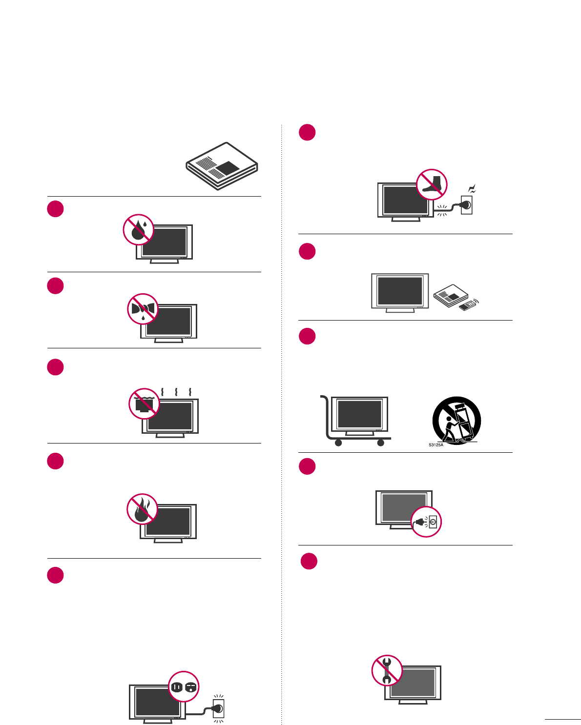
Do not use this apparatus near water.
Clean only with dry cloth.
Do not block any ventilation openings. Install in
accordance with the manufacturer’s instructions.
Do not install near any heat sources such as
radiators, heat registers, stoves, or other
apparatus (including amplifiers)that produce
heat.
Do not defeat the safety purpose of the polarized
or grounding-type plug. A polarized plug has
two blades with one wider than the other. A
grounding type plug has two blades and a
third grounding prong, The wide blade or the
third prong are provided for your safety. If the
provided plug does not fit into your outlet,
consult an electrician for replacement of the
obsolete outlet.
Protect the power cord from being walked on
or pinched particularly at plugs, convenience
receptacles, and the point where they exit from
the apparatus.
Only use attachments/accessories specified by
the manufacturer.
Use only with the cart, stand, tripod, bracket,
or table specified by the manufacturer, or sold
with the apparatus. When a cart is used, use
caution when moving the cart/apparatus com-
bination to avoid injury from tip-over.
Unplug this apparatus during lighting storms
or when unused for long periods of time.
Refer all servicing to qualified service personnel.
Servicing is required when the apparatus has
been damaged in any way, such as power-
supply cord or plug is damaged, liquid has
been spilled or objects have fallen into the
apparatus, the apparatus has been exposed to
rain or moisture, does not operate normally, or
has been dropped.
1
2
3
4
5
7
8
6
9
10
4
SAFETY INSTRUCTIONS
Never touch this apparatus or antenna during
a thunder or lighting storm.
When mounting a TV on the wall, make sure
not to install the TV by the hanging power and
signal cables on the back of the TV.
Do not allow an impact shock or any objects to
fall into the product, and do not drop onto the
screen with something.
CAUTION concerning the Power Cord:
It is recommend that appliances be placed
upon a dedicated circuit; that is, a single
outlet circuit which powers only that appliance
and has no additional outlets or branch
circuits. Check the specification page of this
owner's manual to be certain.
Do not connect too many appliances to the
same AC power outlet as this could result in
fire or electric shock.
Do not overload wall outlets. Overloaded wall
outlets, loose or damaged wall outlets, extension
cords, frayed power cords, or damaged or
cracked wire insulation are dangerous. Any of
these conditions could result in electric shock
or fire. Periodically examine the cord of your
appliance, and if its appearance indicates damage
or deterioration, unplug it, discontinue use of
the appliance, and have the cord replaced with
an exact replacement part by an authorized
servicer. Protect the power cord from physical
or mechanical abuse, such as being twisted,
kinked, pinched, closed in a door, or walked
upon. Pay particular attention to plugs, wall
outlets, and the point where the cord exits the
appliance.
Do not make the TV with the power cord
plugged in. Do not use a damaged or loose
power cord. Be sure do grasp the plug when
unplugging the power cord. Do not pull on the
power cord to unplug the TV.
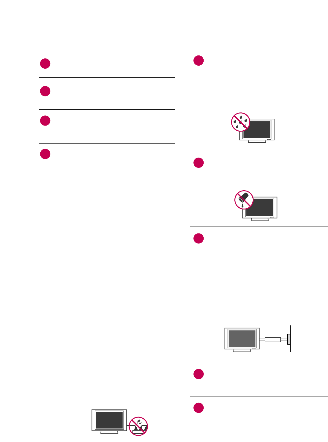
WARNING - To reduce the risk of fire or electrical
shock, do not expose this product to rain,
moisture or other liquids. Do not touch the TV
with wet hands. Do not install this product
near flammable objects such as gasoline or
candles or expose the TV to direct air
conditioning.
Do not expose to dripping or splashing and do
not place objects filled with liquids, such as
vases, cups, etc. on or over the apparatus (e.g.
on shelves above the unit).
GGRROOUUNNDDIINNGG
Ensure that you connect the earth ground wire
to prevent possible electric shock (i.e. a TV
with a three-prong grounded AC plug must be
connected to a three-prong grounded AC out-
let). If grounding methods are not possible,
have a qualified electrician install a separate
circuit breaker.
Do not try to ground the unit by connecting it
to telephone wires, lightening rods, or gas
pipes.
DDIISSCCOONNNNEECCTTIINNGG DDEEVVIICCEE FFRROOMM MMAAIINNSS
Mains plug is the disconnecting device. The
plug must remain readily operable.
Keep the product away from direct sunlight.
12
11
14
13
16
17
18
19
Power
Supply
Short-circuit
Breaker
15
5
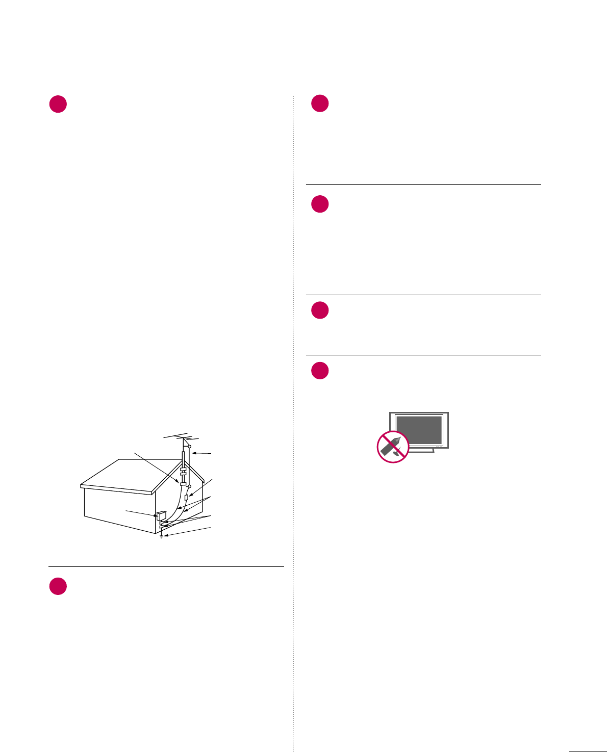
AANNTTEENNNNAASS
OOuuttddoooorr aanntteennnnaa ggrroouunnddiinngg
If an outdoor antenna is installed, follow the
precautions below. An outdoor antenna system
should not be located in the vicinity of over-
head power lines or other electric light or
power circuits, or where it can come in contact
with such power lines or circuits as death or
serious injury can occur.
Be sure the antenna system is grounded so as
to provide some protection against voltage
surges and built-up static charges.
Section 810 of the National Electrical Code
(NEC) in the U.S.A. provides information with
respect to proper grounding of the mast and
supporting structure, grounding of the lead-in
wire to an antenna discharge unit, size of
grounding conductors, location of antenna dis-
charge unit, connection to grounding elec-
trodes and requirements for the grounding
electrode.
AAnntteennnnaa ggrroouunnddiinngg aaccccoorrddiinngg ttoo tthhee
NNaattiioonnaall EElleeccttrriiccaall CCooddee,, AANNSSII//NNFFPPAA 7700
CClleeaanniinngg
When cleaning, unplug the power cord and
scrub gently with a soft cloth to prevent
scratching. Do not spray water or other liquids
directly on the TV as electric shock may occur.
Do not clean with chemicals such as alcohol,
thinners or benzene.
MMoovviinngg
Make sure the product is turned off,
unplugged and all cables have been removed. It
may take 2 or more people to carry larger TVs.
Do not press against or put stress on the front
panel of the TV.
VVeennttiillaattiioonn
Install your TV where there is proper ventila-
tion. Do not install in a confined space such as
a bookcase. Do not cover the product with
cloth or other materials (e.g.) plastic while
plugged in. Do not install in excessively dusty
places.
If you smell smoke or other odors coming from
the TV or hear strange sounds, unplug the power
cord contact an authorized service center.
Do not press strongly upon the panel with
hand or sharp object such as nail, pencil or
pen, or make a scratch on it.
22
20
23
24
25
21
Antenna Lead in Wire
Antenna Discharge Unit
(NEC Section 810-20)
Grounding Conductor
(NEC Section 810-21)
Ground Clamps
Power Service Grounding
Electrode System (NEC
Art 250, Part H)
Ground Clamp
Electric Service
Equipment
NEC: National Electrical Code

6
CONTENTS
WARNING / CAUTION
. . . . . . . . . . . . . . . . . . . . . . . . . . . . 2
SAFETY INSTRUCTIONS
. . . . . . . . . . . . . . . . . . . . . . . . . . 3
FEATURE OF THIS TV
. . . . . . . . . . . . . . . . . . . . . . . . . . . . . . . 8
PREPARATION
Accessories . . . . . . . . . . . . . . . . . . . . . . . . . . . . . . . . . . . . . . . . . . . . . . . . . . . . . . 9
Front Panel Information . . . . . . . . . . . . . . . . . . . . . . . . . . . . . . . . . . . 10
Back Panel Information . . . . . . . . . . . . . . . . . . . . . . . . . . . . . . . . . . . . . 11
Stand Instruction . . . . . . . . . . . . . . . . . . . . . . . . . . . . . . . . . . . . . . . . . . . . . 12
VESA Wall Mounting . . . . . . . . . . . . . . . . . . . . . . . . . . . . . . . . . . . . . . . . 13
Cable Management . . . . . . . . . . . . . . . . . . . . . . . . . . . . . . . . . . . . . . . . . 14
Desktop Pedestal Installation . . . . . . . . . . . . . . . . . . . . . . . . . . . . 15
Swivel Stand . . . . . . . . . . . . . . . . . . . . . . . . . . . . . . . . . . . . . . . . . . . . . . . . . . . . 15
Attaching the TV to a Desk . . . . . . . . . . . . . . . . . . . . . . . . . . . . . . 15
Securing the TV to the wall to prevent falling when
the TV is used on a stand . . . . . . . . . . . . . . . . . . . . . . . . . . . . . . . . 16
Antenna or Cable Connection . . . . . . . . . . . . . . . . . . . . . . . . . . 17
EXTERNAL EQUIPMENT SETUP
HD Receiver Setup . . . . . . . . . . . . . . . . . . . . . . . . . . . . . . . . . . . . . . . . . 18
DVD Setup . . . . . . . . . . . . . . . . . . . . . . . . . . . . . . . . . . . . . . . . . . . . . . . . . . . . . . 21
VCR Setup . . . . . . . . . . . . . . . . . . . . . . . . . . . . . . . . . . . . . . . . . . . . . . . . . . . . . 23
Other A/V Source Setup . . . . . . . . . . . . . . . . . . . . . . . . . . . . . . . . . 25
PC Setup . . . . . . . . . . . . . . . . . . . . . . . . . . . . . . . . . . . . . . . . . . . . . . . . . . . . . . . . 26
USB Connection . . . . . . . . . . . . . . . . . . . . . . . . . . . . . . . . . . . . . . . . . . . . . 32
Audio Out Connection . . . . . . . . . . . . . . . . . . . . . . . . . . . . . . . . . . . . 33
WATCHING TV / CHANNEL CONTROL
Remote Control Functions . . . . . . . . . . . . . . . . . . . . . . . . . . . . . . . 34
Turning On the TV . . . . . . . . . . . . . . . . . . . . . . . . . . . . . . . . . . . . . . . . . . 36
Channel Selection . . . . . . . . . . . . . . . . . . . . . . . . . . . . . . . . . . . . . . . . . . . 36
Volume Adjustment . . . . . . . . . . . . . . . . . . . . . . . . . . . . . . . . . . . . . . . . . 36
Quick Menu / Favorite Channel Setup . . . . . . . . . . . . . . 37
Initial Setting . . . . . . . . . . . . . . . . . . . . . . . . . . . . . . . . . . . . . . . . . . . . . . . . . . 38
On-Screen Menus Selection . . . . . . . . . . . . . . . . . . . . . . . . . . . . . 39
Channel Setup
- Auto Scan (Auto Tuning) . . . . . . . . . . . . . . . . . . . . . . . . . . . 40
- Add / Delete Channel (Manual Tuning) . . . . . . 41
- Channel Editing . . . . . . . . . . . . . . . . . . . . . . . . . . . . . . . . . . . . . . . . 42
Input List . . . . . . . . . . . . . . . . . . . . . . . . . . . . . . . . . . . . . . . . . . . . . . . . . . . . . . . . 43
Input Label . . . . . . . . . . . . . . . . . . . . . . . . . . . . . . . . . . . . . . . . . . . . . . . . . . . . . 44
AV Mode . . . . . . . . . . . . . . . . . . . . . . . . . . . . . . . . . . . . . . . . . . . . . . . . . . . . . . . . 45
SIMPLINK . . . . . . . . . . . . . . . . . . . . . . . . . . . . . . . . . . . . . . . . . . . . . . . . . . . . . . . 46
USB
Entry Modes . . . . . . . . . . . . . . . . . . . . . . . . . . . . . . . . . . . . . . . . . . . . . . . . . . . 48
Photo List . . . . . . . . . . . . . . . . . . . . . . . . . . . . . . . . . . . . . . . . . . . . . . . . . . . . . . . 49
Music List . . . . . . . . . . . . . . . . . . . . . . . . . . . . . . . . . . . . . . . . . . . . . . . . . . . . . . . 53
PICTURE CONTROL
Picture Size (Aspect Ratio) Control . . . . . . . . . . . . . . . . . . 56
Preset Picture Settings
- Picture Mode - Preset . . . . . . . . . . . . . . . . . . . . . . . . . . . . . . . 58
- Color Tone - Preset . . . . . . . . . . . . . . . . . . . . . . . . . . . . . . . . . . . 59
Manual Picture Adjustment
- Picture Mode - User Mode . . . . . . . . . . . . . . . . . . . . . . . . 60
- Picture Mode - Expert Control . . . . . . . . . . . . . . . . . . . 61
Picture Improvement Technology . . . . . . . . . . . . . . . . . . . . . 62
Advanced Control - Black (Darkness) Level . . . . . . . 63
Advanced Control - Eye Care . . . . . . . . . . . . . . . . . . . . . . . . . . . 64
Advanced Control - Real Cinema . . . . . . . . . . . . . . . . . . . . . . 65
Picture Reset . . . . . . . . . . . . . . . . . . . . . . . . . . . . . . . . . . . . . . . . . . . . . . . . . 66
Power Indicator . . . . . . . . . . . . . . . . . . . . . . . . . . . . . . . . . . . . . . . . . . . . . . 67

7
SOUND & LANGUAGE CONTROL
Auto Volume Leveler (Auto Volume) . . . . . . . . . . . . . . . . . 68
Preset Sound Settings (Sound Mode) . . . . . . . . . . . . . . 69
Sound Setting Adjustment - User Mode . . . . . . . . . . . 70
Clear Voice . . . . . . . . . . . . . . . . . . . . . . . . . . . . . . . . . . . . . . . . . . . . . . . . . . . . . 71
Balance . . . . . . . . . . . . . . . . . . . . . . . . . . . . . . . . . . . . . . . . . . . . . . . . . . . . . . . . . . 72
TV Speakers On/Off Setup . . . . . . . . . . . . . . . . . . . . . . . . . . . . . . 73
Audio Reset . . . . . . . . . . . . . . . . . . . . . . . . . . . . . . . . . . . . . . . . . . . . . . . . . . . 74
Stereo/SAP Broadcast Setup . . . . . . . . . . . . . . . . . . . . . . . . . . . 75
Audio Language . . . . . . . . . . . . . . . . . . . . . . . . . . . . . . . . . . . . . . . . . . . . . . 76
On-Screen Menus Language Selection . . . . . . . . . . . . . . 77
Caption Mode
- Analog Broadcasting System Captions . . . . . . . 78
- Digital Broadcasting System Captions . . . . . . . . 79
- Caption Option . . . . . . . . . . . . . . . . . . . . . . . . . . . . . . . . . . . . . . . 80
TIME SETTING
Clock Setting
- Auto Clock Setup . . . . . . . . . . . . . . . . . . . . . . . . . . . . . . . . . . . . . 81
- Manual Clock Setup . . . . . . . . . . . . . . . . . . . . . . . . . . . . . . . . . 82
Auto On/Off Time Setting . . . . . . . . . . . . . . . . . . . . . . . . . . . . . . 83
Sleep Timer Setting . . . . . . . . . . . . . . . . . . . . . . . . . . . . . . . . . . . . . . . . . 84
Auto Shut-off Setting . . . . . . . . . . . . . . . . . . . . . . . . . . . . . . . . . . . . . . . 85
PARENTAL CONTROL / RATINGS
Set Password & Lock System . . . . . . . . . . . . . . . . . . . . . . . . . . . 86
Channel Blocking . . . . . . . . . . . . . . . . . . . . . . . . . . . . . . . . . . . . . . . . . . . . 89
Movie & TV Rating . . . . . . . . . . . . . . . . . . . . . . . . . . . . . . . . . . . . . . . . . 90
Downloadable Rating . . . . . . . . . . . . . . . . . . . . . . . . . . . . . . . . . . . . . . 95
External Input Blocking . . . . . . . . . . . . . . . . . . . . . . . . . . . . . . . . . . . . 96
Key lock . . . . . . . . . . . . . . . . . . . . . . . . . . . . . . . . . . . . . . . . . . . . . . . . . . . . . . . . . . 97
APPENDIX
Troubleshooting . . . . . . . . . . . . . . . . . . . . . . . . . . . . . . . . . . . . . . . . . . . . . . 98
Maintenance . . . . . . . . . . . . . . . . . . . . . . . . . . . . . . . . . . . . . . . . . . . . . . . . . 10 0
Product Specifications . . . . . . . . . . . . . . . . . . . . . . . . . . . . . . . . . . . 101
Programming the Remote Control . . . . . . . . . . . . . . . . . 102
IR Codes . . . . . . . . . . . . . . . . . . . . . . . . . . . . . . . . . . . . . . . . . . . . . . . . . . . . .105
External Control Through RS-232C . . . . . . . . . . . . . . . . .107
8
FEATURE OF THIS TV
is a trademark of SRS Labs, Inc.
TruSurround XT technology is incorporated under
license from SRS Labs, Inc.
Manufactured under license from Dolby Laboratories.
“
Dolby
“and the double-D symbol are trademarks of
Dolby Laboratories.
FOR LCD TV
■
If the TV feels cold to the touch, there may be a small “flicker” when it is turned on. This is normal, there is
nothing wrong with TV.
■
Some minute dot defects may be visible on the screen, appearing as tiny red, green, or blue spots. However, they
have no adverse effect on the monitor's performance.
■
Avoid touching the LCD screen or holding your finger(s) against it for long periods of time. Doing so may produce
some temporary distortion effects on the screen.
On Disposal (Only Hg lamp used LCD TV)
The fluorescent lamp used in this product contains a small amount of mercury. Do not dispose of this product with
general household waste. Disposal of this product must be carried out in accordance to the regulations of your local
authority.
CALIBRATE LIKE A PRO: Sophisticated and detailed
calibrations can be made through the ISFccc mode.
Detailed calibration requires a licensed technician.
Please contact your local dealer to inquire about an
ISF certified technician.
PREPARATION
9
PREPARATION
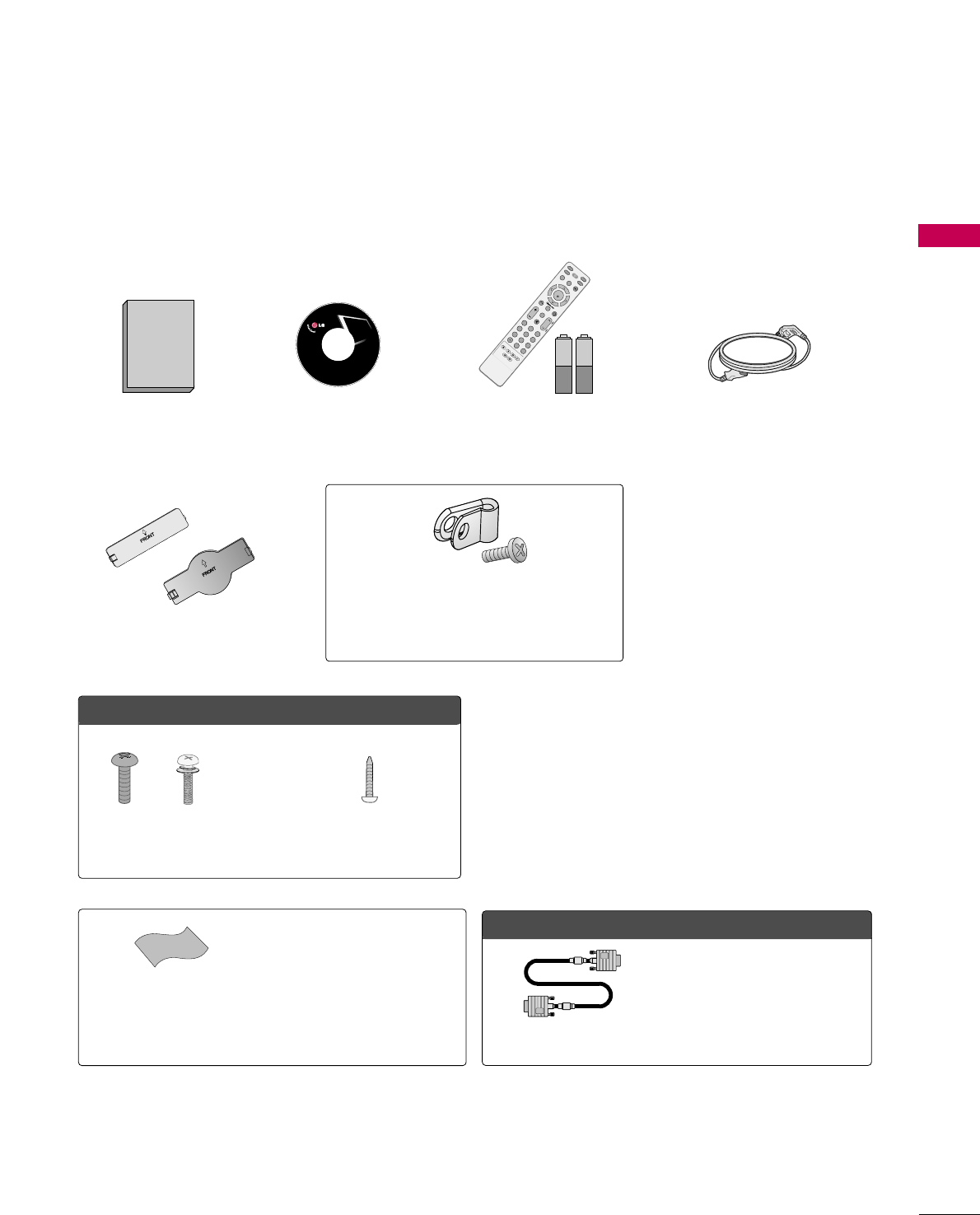
ACCESSORIES
Ensure that the following accessories are included with your TV. If an accessory is missing, please contact the
dealer where you purchased the TV.
The accessories included may differ from the images below.
OOppttiioonn EExxttrraass
* Wipe spots on the exterior only with
the polishing cloth.
* Do not wipe roughly when removing
stain. Excessive pressure may cause
scratch or discoloration.
Polishing Cloth
(This feature is not available
for all models.)
Copyright© 2007 LGE,
All Rights Reserved.
D-sub 15 pin Cable
1.5V 1.5V
Owner’s Manual Power Cord
Remote Control,
Batteries
INPUT
FAV
MUTE
TV
STB
POWER
Q. MENUMENU
AV MODE
RETURN
ENTER
VOLCH
123
456
78
0
9
FLASHBK
P
A
G
E
DVD
VCR
CD Manual
When using the VGA (D-sub 15 pin
cable) PC connection, the user
must use shielded signal interface
cables with ferrite cores to maintain
standards compliance.
Protection Cover
or
Protective Bracket and Bolt for
Power Cord
(This feature is not available for all models.)
(Refer to P.14)
OOnnllyy 3377//4422LLGG55**
Bolts for stand assembly
(Refer to P.12) Screw for stand fixing
(Refer to P.15)
x 4 x 4
PREPARATION
10
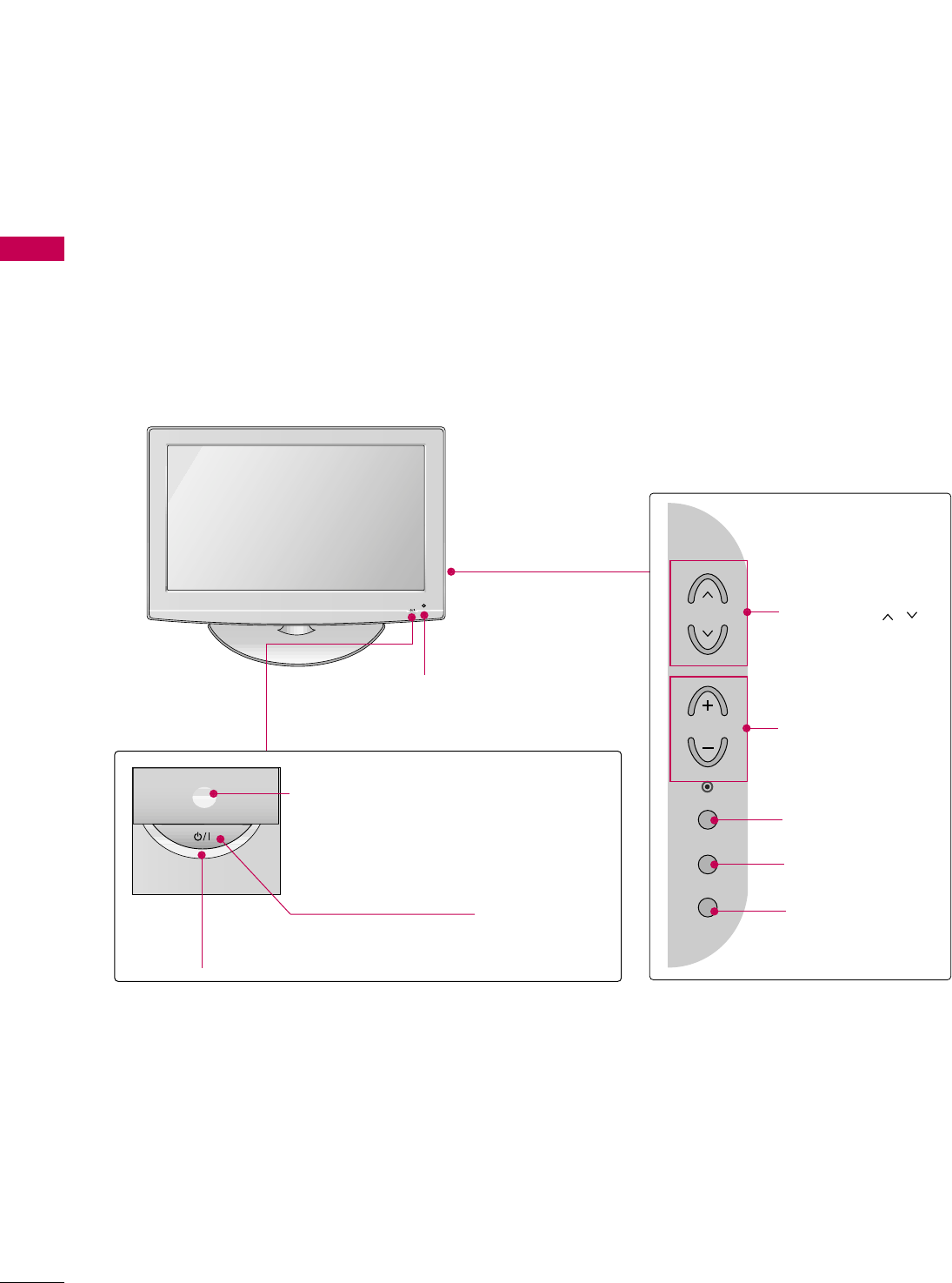
FRONT PANEL INFORMATION
PREPARATION
■
Image shown may differ from your TV.
■
NOTE: If your TV has a protection tape attached, remove the tape.
And then wipe the TV with a cloth (If a polishing cloth is included with your TV, use it).
POWER Button
Power/Standby Indicator
Illuminates red in standby mode.
Illuminates blue when the set is switched on.
(Can be adjusted using PPoowweerr IInnddiiccaattoorrin
the OPTION menu. GGpp..6677)
CH
VOL
MENU
INPUT
ENTER
CHANNEL ( , )
Buttons
VOLUME (+, -)
Buttons
ENTER Button
MENU Button
INPUT Button
Intelligent Sensor
Adjusts picture according to the
surrounding conditions
Remote Control Sensor
PREPARATION
11
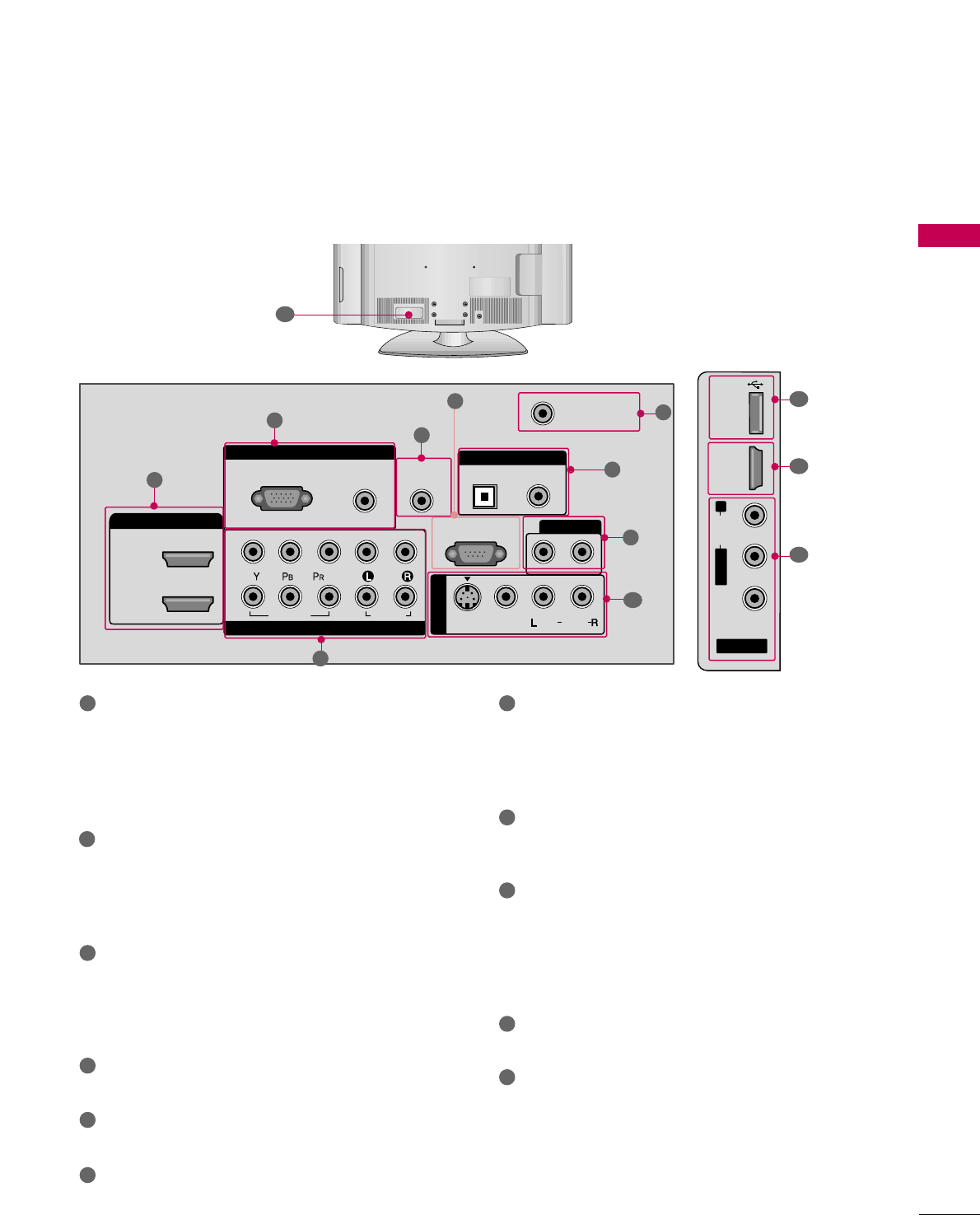
BACK PANEL INFORMATION
■
Image shown may differ from your TV.
AV IN 2
L/MONO
R
AUDIO
VIDEO
HDMI IN 3 USB IN
( )
RGB IN
COMPONENT IN
AUDIO
(RGB/DVI)
RGB(PC)
REMOTE
CONTROL IN
ANTENNA/
CABLE IN
1
2
RS-232C IN
(CONTROL & SERVICE)
VIDEO
AUDIO
OPTICAL COAXIAL
DIGITAL AUDIO OUT
AUDIO OUT
AV IN 1
R
HDMI/DVI IN
2
1
VIDEO
MONO
( )
AUDIO
S-VIDEO
1
34
6
7
8
2
9
5
1
R
( )
11
HDMI/DVI IN, HDMI IN
Digital Connection.
Supports HD video and Digital audio. Doesn’t
support 480i.
Accepts DVI video using an adapter or HDMI to
DVI cable (not included).
COMPONENT IN
Analog Connection.
Supports HD.
Uses a red, green, and blue cable for video & red
and white for audio.
RGB (PC)
Analog PC Connection. Uses a D-sub 15 pin cable
(VGA cable).
AUDIO (RGB/DVI)
1/8” headphone jack for analog PC audio input.
REMOTE CONTROL IN PORT
For a wired remote control.
RS-232C IN (CONTROL & SERVICE) PORT
Used by third party devices.
ANTENNA/CABLE IN
Connect over-the air signals to this jack.
Connect cable signals to this jack.
DIGITAL AUDIO OUT
Digital audio output for use with amps and home
theater systems.
Includes an optical and coaxial connection.
Note: In standby mode, these ports do not work.
AUDIO OUT
Analog audio output for use with amps and home
theater systems.
AV (Audio/Video) IN
Analog composite connection. Supports standard
definition video only (480i).
S-VIDEO
Better quality than standard composition.
Supports standard definition video only (480i).
USB INPUT
Used for viewing photos and listening to MP3s.
Power Cord Socket
For operation with AC power.
Caution: Never attempt to operate the TV on DC
power.
1
2
3
4
5
6
9
10
11
7
8
10
9
(Except
42/47/52LG50DC)
PREPARATION
12
STAND INSTRUCTION
PREPARATION
■
Image shown may differ from your TV.
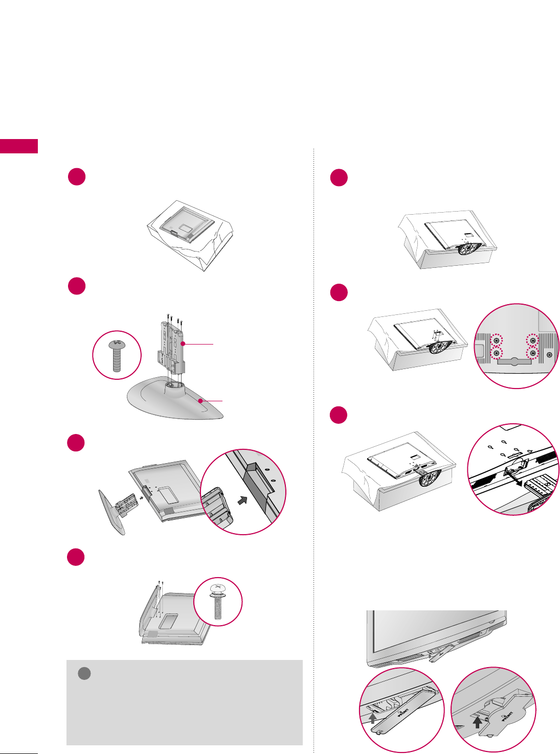
Assemble the parts of the SSTTAANNDD BBOODDYY
with CCOOVVEERR BBAASSEEof the TV.
2
Assemble the TV as shown.
3
Fix the 4 bolts securely using the holes in the
back of the TV.
4
SSTTAANNDD BBOODDYY
CCOOVVEERR BBAASSEE
Carefully place the TV screen side down on a cush-
ioned surface to protect the screen from damage.
1
INSTALLATION
(Only 37/42LG5*)
DETACHMENT
Carefully place the TV screen side down on a
cushioned surface to protect the screen from
damage.
1
Loose the bolts from TV.
2
Detach the stand from TV.
3
After removing the stand, install the included
pprrootteeccttiioonn ccoovveerrover the hole for the stand.
Press the PPRROOTTEECCTTIIOONN CCOOVVEERRinto the TV
until you hear it click.
PROTECTION COVER
GGWhen assembling the desk type stand, make sure
the bolt is fully tightened (If not tightened fully,
the TV can tilt forward after the product installa-
tion). Do not over tighten.
NOTE
!
PREPARATION
13
VESA WALL MOUNTING
Install your wall mount on a solid wall perpendicular to the floor. When attaching to other building materials, please
contact your nearest dealer.
If installed on a ceiling or slanted wall, it may fall and result in severe personal injury.
We recommend that you use an LG brand wall mount when mounting the TV to a wall.
LG recommends that wall mounting be performed by a qualified professional installer.
GGDo not install your wall mount kit while your TV is turned on. It may result in personal injury due to electric
shock.
CAUTION
GGScrew length needed depends on the wall mount
used. For further information, refer to the instruc-
tions included with the mount.
GGStandard dimensions for wall mount kits are shown
in the table.
GGWhen purchasing our wall mount kit, a detailed
installation manual and all parts necessary for
assembly are provided.
GGDo not use screws longer then the standard dimen-
sion, as they may cause damage to the inside to
the TV.
GGFor wall mounts that do not comply with the VESA
standard screw specifications, the length of the
screws may differ depending on their specifica-
tions.
GGDo not use screws that do not comply with the
VESA standard screw specifications.
Do not use fasten the screws too strongly, this may
damage the TV or cause the TV to a fall, leading to
personal injury. LG is not liable for these kinds of
accidents.
GGLG is not liable for TV damage or personal injury
when a non-VESA or non specified wall mount is
used or the consumer fails to follow the TV installa-
tion instructions.
NOTE
!
AA
BB
Product Model VESA
(A *B) Standard Screw Quantity
37LG5*
42LG5*
47LG5*
52LG5*
200 * 200
800 * 400
M6
M6
4
4
LCD TV
PREPARATION
14
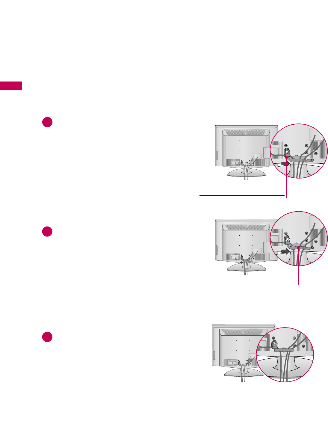
CABLE MANAGEMENT
PREPARATION
Connect the cables as necessary.
To connect additional equipment, see the
EXTERNAL EQUIPMENT SETUP section.
Secure the power cable with the PROTECTIVE
BRACKET and the screw as shown. It will help
prevent the power cable from being removed
by accident.
Install the CABLE MANAGEMENT CLIP as
shown.
CABLE MANAGEMENT CLIP
PROTECTIVE BRACKET
(This feature is not available for all models.)
1
2
Put the cables inside the CABLE MANAGEMENT
CLIP and snap it closed.
3
■
Image shown may differ from your TV.
PREPARATION
15
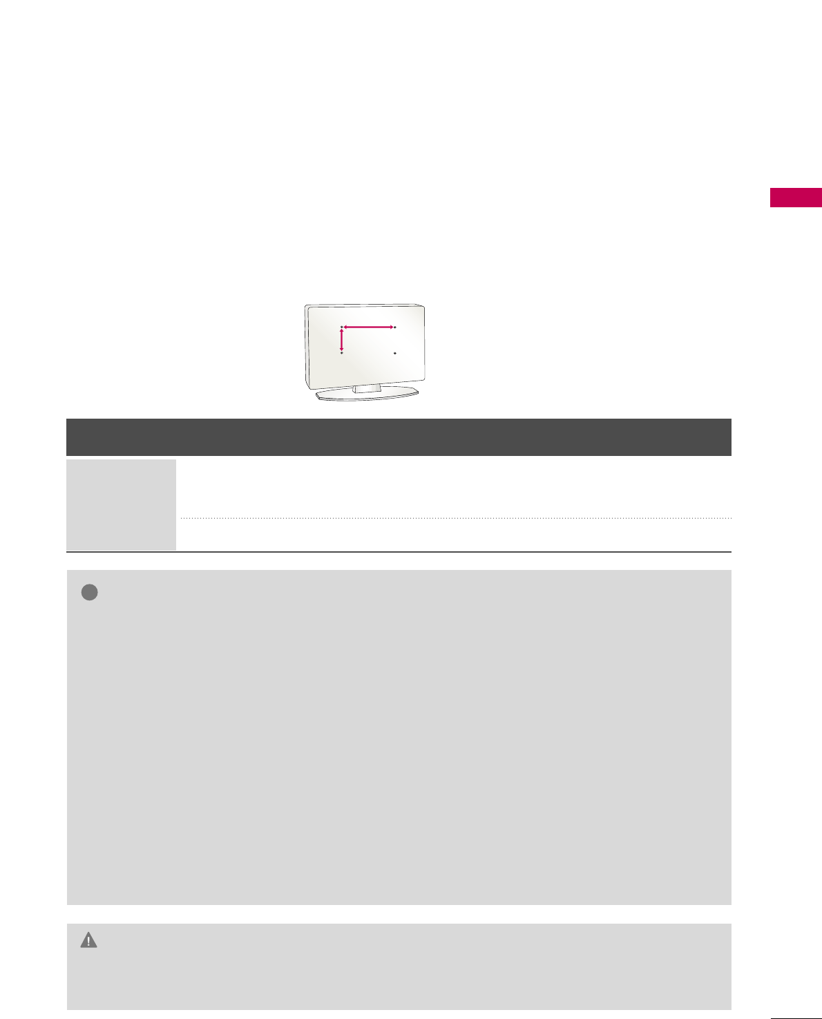
DESKTOP PEDESTAL INSTALLATION
For proper ventilation, allow a clearance of 4 inches on all four sides from the wall.
■
Image shown may differ from your TV.
4 inches
4 inches
4 inches 4 inches
SWIVEL STAND
After installing the TV, you can adjust the TV set manually to the left or right direction by 20 degrees to suit
your viewing position.
GGEnsure adequate ventilation by following the clearance recommendations.
GGDo not mount near or above any type of heat source.
CAUTION
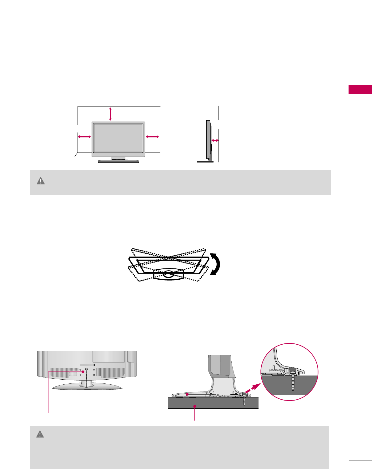
ATTACHING THE TV TO A DESK (Only 37/42LG5*)
The TV must be attached to a desk so it cannot be pulled in a forward/backward direction, potentially causing
injury or damaging the product.
GGTo prevent TV from falling over, the TV should be securely attached to the floor/wall per installation
instructions. Tipping, shaking, or rocking the machine may cause injury.
WARNING
1-Screw
(provided as parts of the product)
Desk
Stand
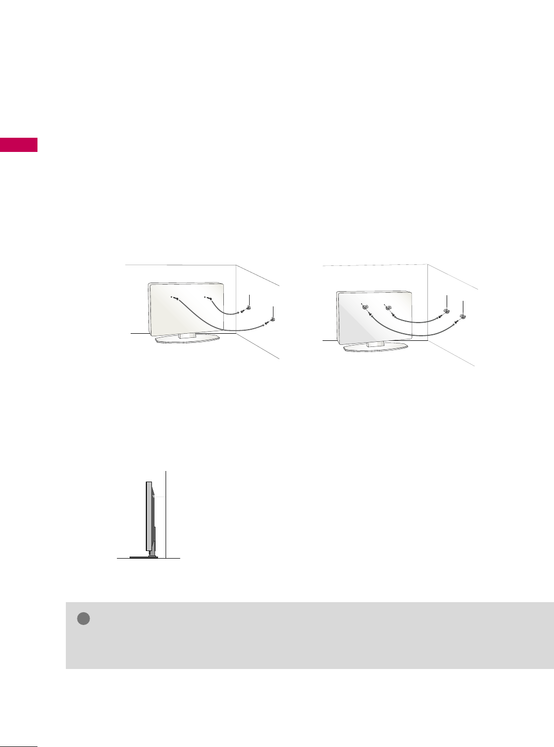
We recommend that you set up the TV close to a wall so it cannot fall over if pushed backwards.
Additionally, we recommend that the TV be attached to a wall so it cannot be pulled in a forward direction,
potentially causing injury or damaging the product.
Caution: Please make sure that children don’t climb on or hang from the TV.
■Insert the eye-bolts (or TV brackets and bolts) to tighten the product to the wall as shown in the picture.
*If your product has the bolts in the eye-bolts position before inserting the eye-bolts, loosen the bolts.
* Insert the eye-bolts or TV brackets/bolts and tighten them securely in the upper holes.
Secure the wall brackets with the bolts (sold separately) to the wall. Match the height of the bracket that is
mounted on the wall to the holes in the product.
Ensure the eye-bolts or brackets are tightened securely.
■Use a sturdy rope (sold separately) to tie the product. It is safer to tie
the rope so it becomes horizontal between the wall and the product.
■
You should purchase necessary components to prevent TV from falling off of the stand.
■
Image shown may differ from your TV.
GGUse a platform or cabinet strong enough and large enough to support the size and weight of the TV.
GGTo use the TV safely make sure that the height of the bracket on the wall and the one on the TV are the same.
NOTE
!
PREPARATION
16
SECURING THE TV TO THE WALL TO PREVENT FALLING
WHEN THE TV IS USED ON A STAND
PREPARATION
PREPARATION
17
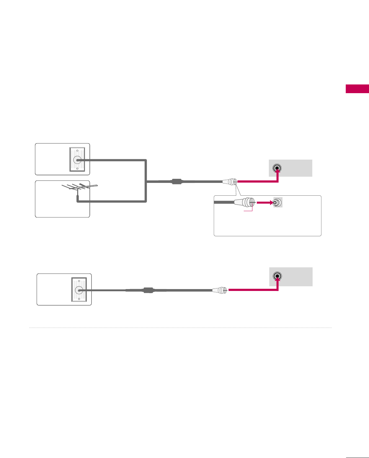
ANTENNA OR CABLE CONNECTION
1. Antenna (Analog or Digital)
Wall Antenna Socket or Outdoor Antenna without a Cable Box
Connection.
For optimum picture quality, adjust the antenna direction if needed.
2. Cable
Wall
Antenna
Socket
Outdoor
Antenna
(VHF, UHF)
Cable TV
Wall Jack
Multi-family Dwellings/Apartments
(Connect to wall antenna socket)
RF Coaxial Wire (75 ohm)
RF Coaxial Wire (75 ohm)
Single-family Dwellings /Houses
(Connect to wall jack for outdoor antenna)
Be careful not to bend the copper wire
when connecting the antenna.
Copper Wire
■To improve the picture quality in a poor signal area, please purchase a signal amplifier and install properly.
■If the antenna needs to be split for two TV’s, install a 2-Way Signal Splitter.
■If the antenna is not installed properly, contact your dealer for assistance.
ANTENNA/
CABLE IN
R
( )
ANTENNA/
CABLE IN
R
( )
■To prevent damage do not connect to the power outlet until all connections are made between the devices.
EXTERNAL EQUIPMENT SETUP
18
HD RECEIVER SETUP
EXTERNAL EQUIPMENT SETUP
This TV can receive digital over-the-air/digital cable signals without an external digital set-top box. However, if
you do receive digital signals from a digital set-top box or other digital external device.
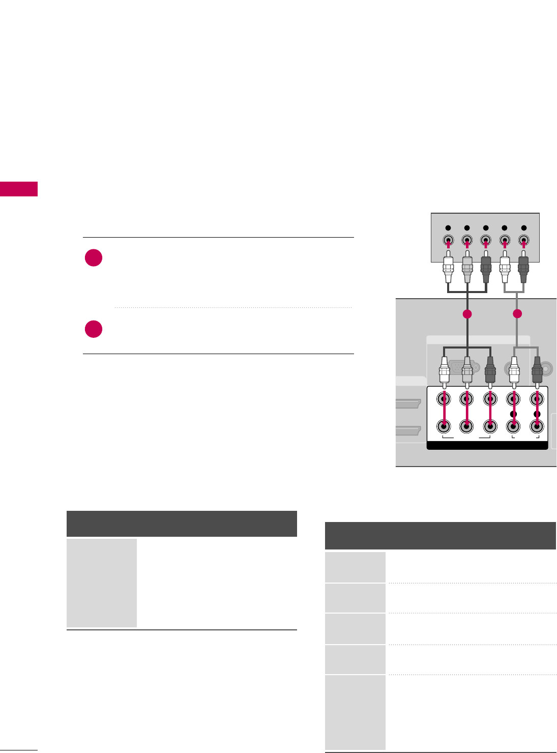
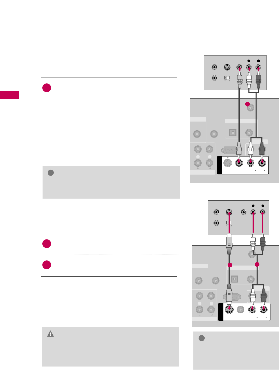
Component Connection
1. How to connect
Connect the video outputs (Y, PB, PR)of the digital set-
top box to the CCOOMMPPOONNEENNTT IINN VVIIDDEEOO 11jacks on
the TV. Match the jack colors (Y = green, PB= blue, and
PR= red).
Connect the audio output of the digital set-top box to
the CCOOMMPPOONNEENNTT IINN AAUUDDIIOO 11jacks on the TV.
2
1
2. How to use
■Turn on the digital set-top box.
(Refer to the owner’s manual for the digital set-top box. operation)
■Select the CCoommppoonneenntt11input source on the TV using
the IINNPPUUTTbutton on the remote control.
■If connected to CCOOMMPPOONNEENNTT IINN22input, select the
CCoommppoonneenntt 22input source on the TV.
■To prevent the equipment damage, never plug in any power cords until you have finished connecting all equipment.
■
Image shown may differ from your TV.
Y, CB/PB, CR/PR
Supported Resolutions
Horizontal Vertical
Frequency(KHz)Frequency(Hz)
15.73 59.94
15.73 60.00
31.47 59.94
31.50 60.00
44.96 59.94
45.00 60.00
33.72 59.94
33.75 60.00
26.97 23.976
27.00 24.00
33.71 29.97
33.75 30.00
67.432 59.94
67.50 60.00
Resolution
720x480i
720x480p
1280x720p
1920x1080i
1920x1080p
Signal
480i
480p
720p
1080 i
1080 p
Component
Yes
Yes
Yes
Yes
Yes
HDMI
No
Yes
Yes
Yes
Yes
RGB IN
AUDIO
(RGB/DVI)
RGB(PC)
REMOTE
CONTROL
(C
DVI IN
COMPONENT IN
1
2
VIDEO
LYP
BPRR
AUDIO
Y L RPBPR
12
EXTERNAL EQUIPMENT SETUP
19
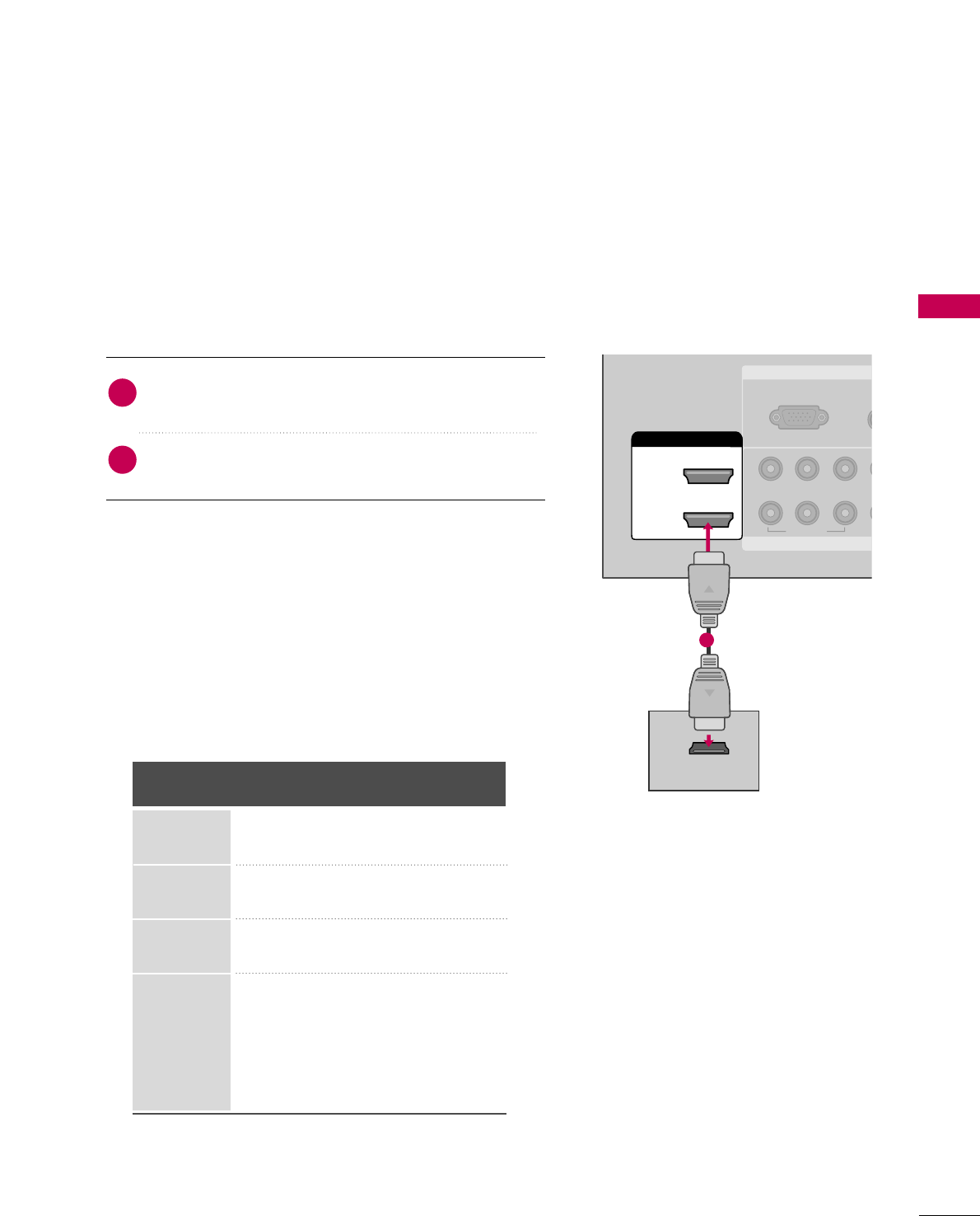
HDMI Connection
Connect the digital set-top box to HHDDMMII//DDVVII IINN11,
22, or 33* jack on the TV.
No separate audio connection is necessary.
HDMI supports both audio and video.
1. How to connect
2. How to use
■Turn on the digital set-top box.
(Refer to the owner’s manual for the digital set-top box.)
■Select the HHDDMMII11,HHDDMMII22,orHHDDMMII33* input source on the
TV using the IINNPPUUTTbutton on the remote control.
2
1
HDMI-DTV
Horizontal Vertical
Frequency(KHz)Frequency(Hz)
31.47 59.94
31.50 60.00
44.96 59.94
45.00 60.00
33.72 59.94
33.75 60.00
26.97 23.976
27.00 24.00
33.71 29.97
33.75 30.00
67.432 59.939
67.50 60.00
Resolution
720x480p
1280x720p
1920x1080i
1920x1080p
RGB IN
COMPONENT
A
(RG
RGB(PC)
1
2
VIDEO
YP
BPR
HDMI/DVI IN
2
1
HDMI-DTV OUTPUT
1
* HDMI 3: Except 42/47/52LG50DC
EXTERNAL EQUIPMENT SETUP
20
EXTERNAL EQUIPMENT SETUP
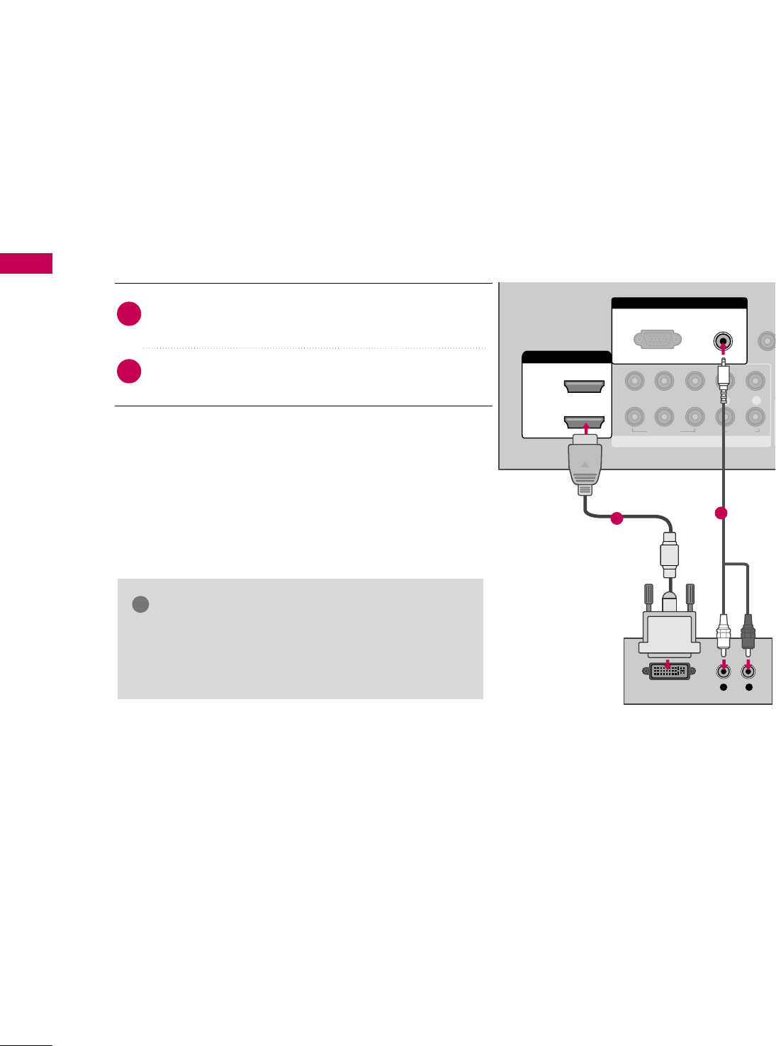
Connect the DVI output of the digital set-top box to
the HHDDMMII//DDVVII IINN 11, 22, or 33* jack on the TV.
Connect the PC audio output to the AAUUDDIIOO
((RRGGBB//DDVVII))jack on the TV.
1. How to connect
2. How to use
■Turn on the digital set-top box. (Refer to the owner’s manu-
al for the digital set-top box.)
■Select the HHDDMMII11,HHDDMMII22,orHHDDMMII33* input source on the
TV using the IINNPPUUTTbutton on the remote control.
2
1
DVI to HDMI Connection
GGA DVI to HDMI cable or adapter is required for this
connection. DVI doesn't support audio, so a separate
audio connection is necessary.
NOTE
!
RGB IN
COMPONENT IN
AUDIO
(RGB/DVI)
RGB(PC)
REMO
CONTRO
1
2
VIDEO
LYP
BPRR
AUDIO
HDMI/DVI IN
2
1
L R
DVI-DTV OUTPUT
12
* HDMI 3: Except 42/47/52LG50DC
EXTERNAL EQUIPMENT SETUP
21
DVD SETUP
Component Connection
Component Input ports
To get better picture quality, connect a DVD player to the component input ports as shown below.
Component ports on the TV
YP
BPR
Video output ports
on DVD player
Y
Y
Y
Y
PB
B-Y
Cb
Pb
PR
R-Y
Cr
Pr
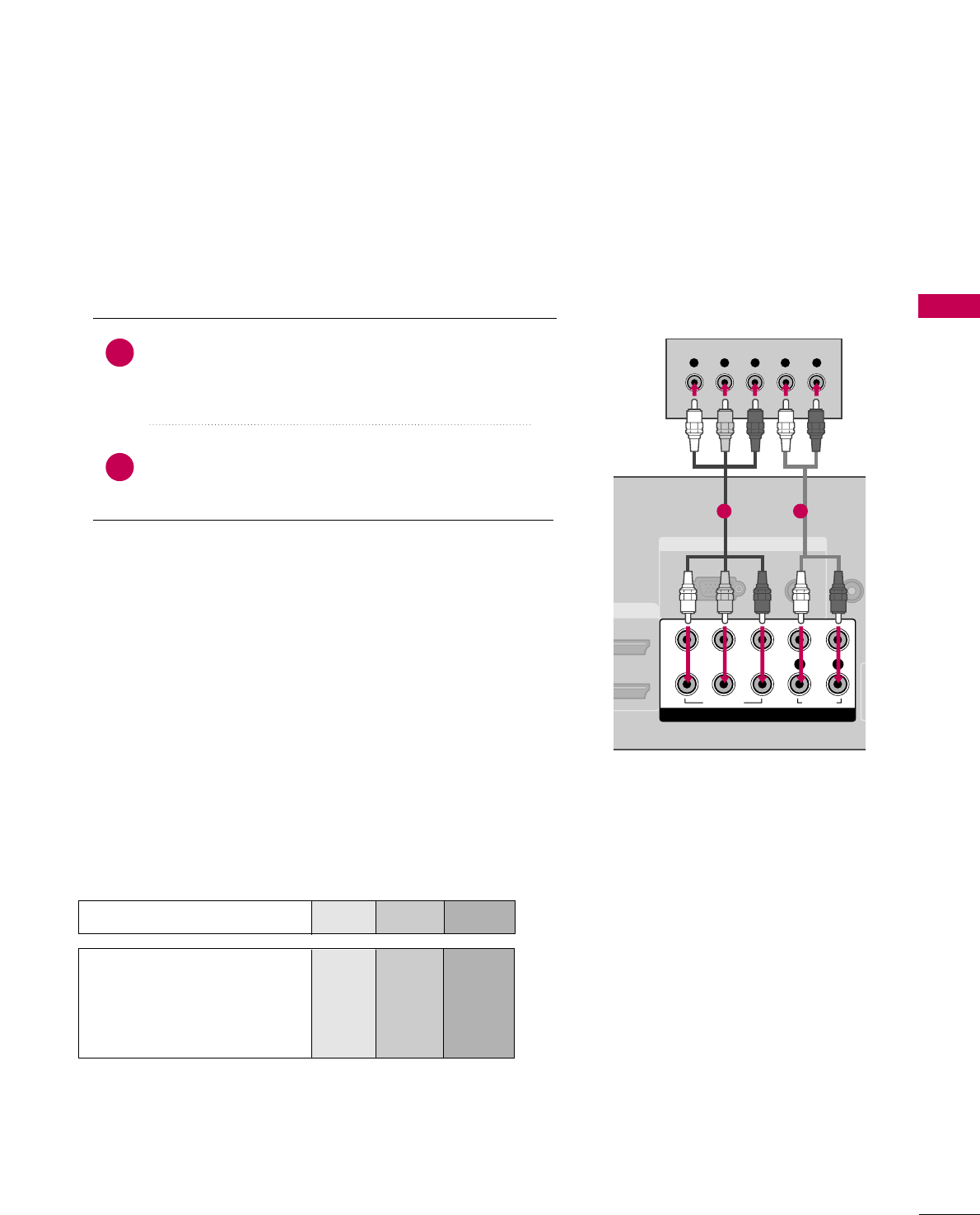
Connect the video outputs (Y, PB, PR)of the DVD to the
CCOOMMPPOONNEENNTT IINN VVIIDDEEOO11jacks on the TV.
Match the jack colors (Y = green, PB= blue, and PR= red).
Connect the audio outputs of the DVD to the
CCOOMMPPOONNEENNTT IINN AAUUDDIIOO11jacks on the TV.
1. How to connect
2. How to use
■Turn on the DVD player, insert a DVD.
■Select the CCoommppoonneenntt11input source on the TV using
the IINNPPUUTTbutton on the remote control.
■If connected to CCOOMMPPOONNEENNTT IINN 22input, select the
CCoommppoonneenntt 22input source on the TV.
■Refer to the DVD player's manual for operating instructions.
2
1
RGB IN
AUDIO
(RGB/DVI)
RGB(PC)
REMOT
CONTROL
(
VI IN
COMPONENT IN
1
2
VIDEO
LYP
BPRR
AUDIO
Y L RPBPR
1 2
EXTERNAL EQUIPMENT SETUP
22
EXTERNAL EQUIPMENT SETUP
S-Video Connection
N
DIO
B/DVI)
REMOTE
CONTROL IN
ANTENNA/
CABLE IN
RS-232C IN
(CONTROL & SERVICE)
L R
AUDIO
OPTICAL COAXIAL
DIGITAL AUDIO OUT
L R
S-VIDEO
AUDIO
AUDIO OUT
AV IN 1
VIDEO LR
(MONO)
AUDIO
S-VIDEO
12
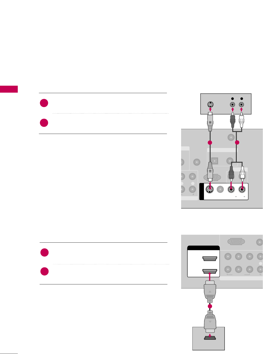
Connect the S-VIDEO output of the DVD to the
SS--VVIIDDEEOOinput on the TV.
Connect the audio outputs of the DVD to the AAUUDDIIOO
input jacks on the TV.
1. How to connect
2. How to use
■Turn on the DVD player, insert a DVD.
■Select the AAVV11input source on the TV using the IINNPPUUTT
button on the remote control.
■Refer to the DVD player's manual for operating instructions.
2
1
HDMI Connection
Connect the HDMI output of the DVD to the
HHDDMMII//DDVVII IINN11, 22, or 33* jack on the TV.
No separate audio connection is necessary.
HDMI supports both audio and video.
1. How to connect
2. How to use
■Select the HHDDMMII11, HHDDMMII22, or HHDDMMII33* input source on
the TV using the IINNPPUUTTbutton on the remote control.
■Refer to the DVD player's manual for operating instructions.
2
1
COMPONENT IN
AUDIO
(RGB/D
RGB(PC)
1
2
VIDEO
LYP
BPR
A
HDMI/DVI IN
2
1
HDMI-DVD OUTPUT
1
* HDMI 3: Except 42/47/52LG50DC
EXTERNAL EQUIPMENT SETUP
23
VCR SETUP
Antenna Connection
■To avoid picture noise (interference), leave an adequate distance between the VCR and TV.
■If the 4:3 picture format is used; the fixed images on the sides of the screen may remain visible on the screen.
This phenomenon is common to all TVs and is not covered by warranty.
ANTENNA/
CABLE IN
E)
COAXIAL
UDIO OUT
L R
S-VIDEO VIDEO
OUTPUT
SWITCH
ANT IN
ANT OUT
EO L R
(MONO)
AUDIO
AUDIO OUT
Wall Jack
Antenna
1
2
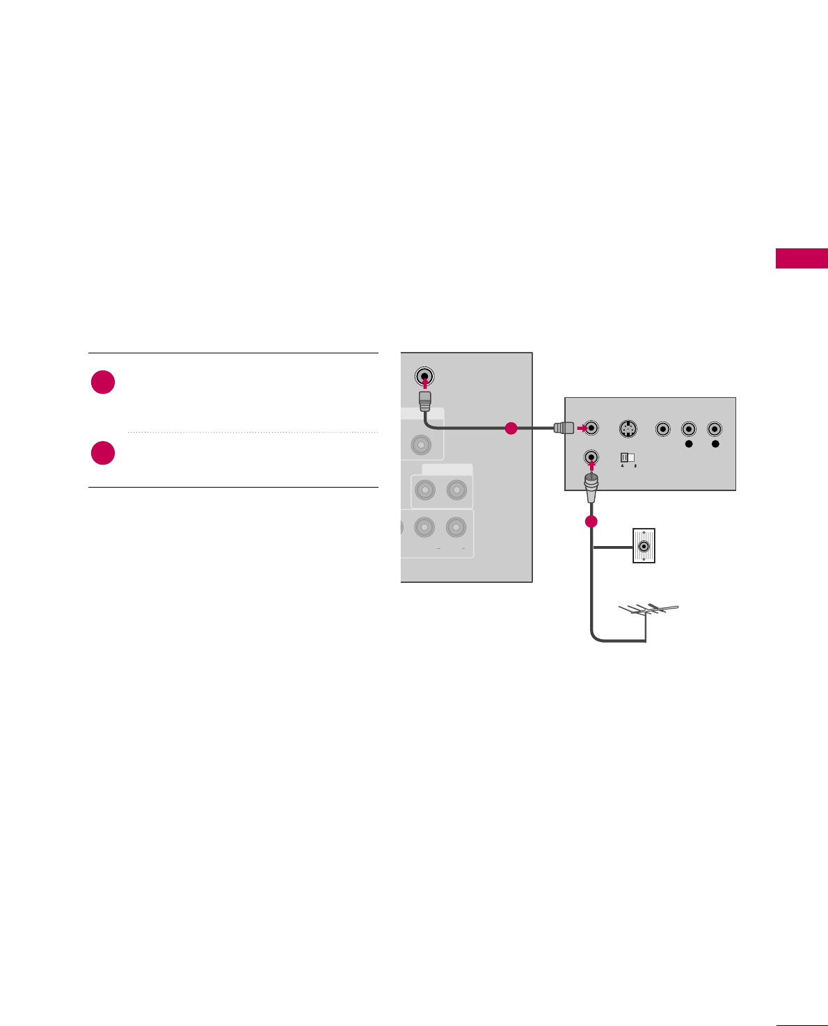
Connect the RF antenna out socket of the
VCR to the AANNTTEENNNNAA//CCAABBLLEE IINNsock-
et on the TV.
Connect the antenna cable to the RF
antenna in socket of the VCR.
1. How to connect
2. How to use
■Set VCR output switch to 3 or 4 and then
tune TV to the same channel number.
■Insert a video tape into the VCR and press
PLAY on the VCR. (Refer to the VCR owner’s
manual.)
2
1
EXTERNAL EQUIPMENT SETUP
24
EXTERNAL EQUIPMENT SETUP
Composite (RCA) Connection
GGIf you have a mono VCR, connect the audio cable from
the VCR to the AAUUDDIIOO LL//MMOONNOOjack of the TV.
NOTE
!
NT IN
AUDIO
(RGB/DVI)
REMOTE
CONTROL IN
ANTENNA/
CABLE IN
RS-232C IN
(CONTROL & SERVICE)
L R
AUDIO
OPTICAL COAXIAL
DIGITAL AUDIO OUT
AV IN 1
VIDEO L R
(MONO)
AUDIO
S-VIDEO
AUDIO OUT
L R
S-VIDEO VIDEO
OUTPUT
SWITCH
ANT IN
ANT OUT
1
Connect the AAUUDDIIOO/VVIIDDEEOOjacks between TV and
VCR. Match the jack colors (Video = yellow, Audio Left
= white, and Audio Right = red)
1. How to connect
2. How to use
■Insert a video tape into the VCR and press PLAY on the VCR.
(Refer to the VCR owner’s manual.)
■Select the AAVV11input source on the TV using the IINNPPUUTT
button on the remote control.
■If connected to AAVV IINN22, select AAVV22input source on the TV.
1
GGDo not connect to both Video and S-Video at the same
time. In the event that you connect both Video and the
S-Video cables, only the S-Video will work.
CAUTION
GGS-Video provides better quality
than composite. Use it when
available.
NOTE
!
S-Video Connection
NT IN
AUDIO
(RGB/DVI)
REMOTE
CONTROL IN
ANTENNA/
CABLE IN
RS-232C IN
(CONTROL & SERVICE)
L R
AUDIO
OPTICAL COAXIAL
DIGITAL AUDIO OUT
AV IN 1
VIDEO LR
(MONO)
AUDIO
S-VIDEO
AUDIO OUT
L R
S-VIDEO VIDEO
OUTPUT
SWITCH
ANT IN
ANT OUT
12
Connect the S-VIDEO output of the VCR to the
SS--VVIIDDEEOO input on the TV.
Connect the audio outputs of the VCR to the AAUUDDIIOO
input jacks on the TV.
1. How to connect
2. How to use
■Insert a video tape into the VCR and press PLAY on the VCR.
(Refer to the VCR owner’s manual.)
■Select the AAVV11input source on the TV using the IINNPPUUTT
button on the remote control.
2
1
EXTERNAL EQUIPMENT SETUP
25
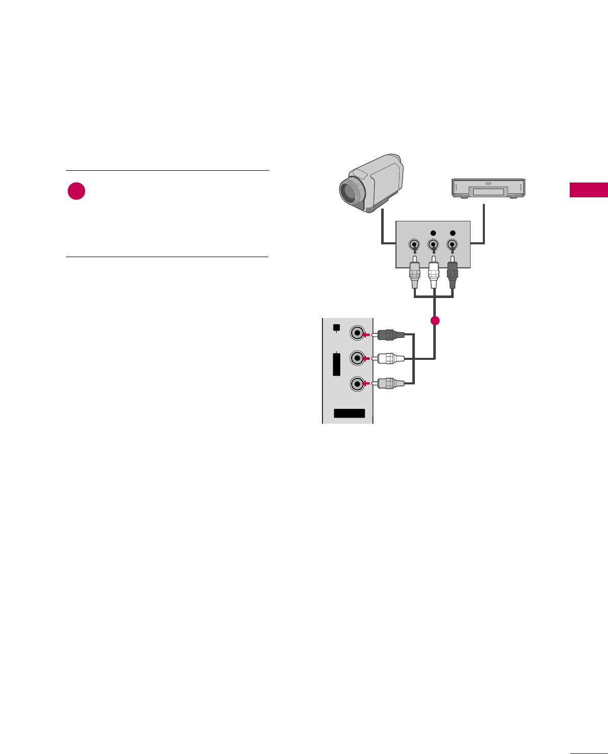
OTHER A/V SOURCE SETUP
AV IN 2
L/MONO
R
AUDIO
VIDEO
HDMI IN 3 USB IN
L R
VIDEO
Camcorder
Video Game Set
Connect the AAUUDDIIOO/VVIIDDEEOOjacks
between TV and external equipment.
Match the jack colors
.
(Video = yellow, Audio Left = white, and
Audio Right = red)
1. How to connect
2. How to use
■Select the AAVV22input source on the TV using
the IINNPPUUTTbutton on the remote control.
■If connected to AAVV IINN11input, select the AAVV11
input source on the TV.
■Operate the corresponding external equipment.
1
1
EXTERNAL EQUIPMENT SETUP
26
PC SETUP
EXTERNAL EQUIPMENT SETUP
This TV provides Plug and Play capability, meaning that the PC adjusts automatically to the TV's settings.
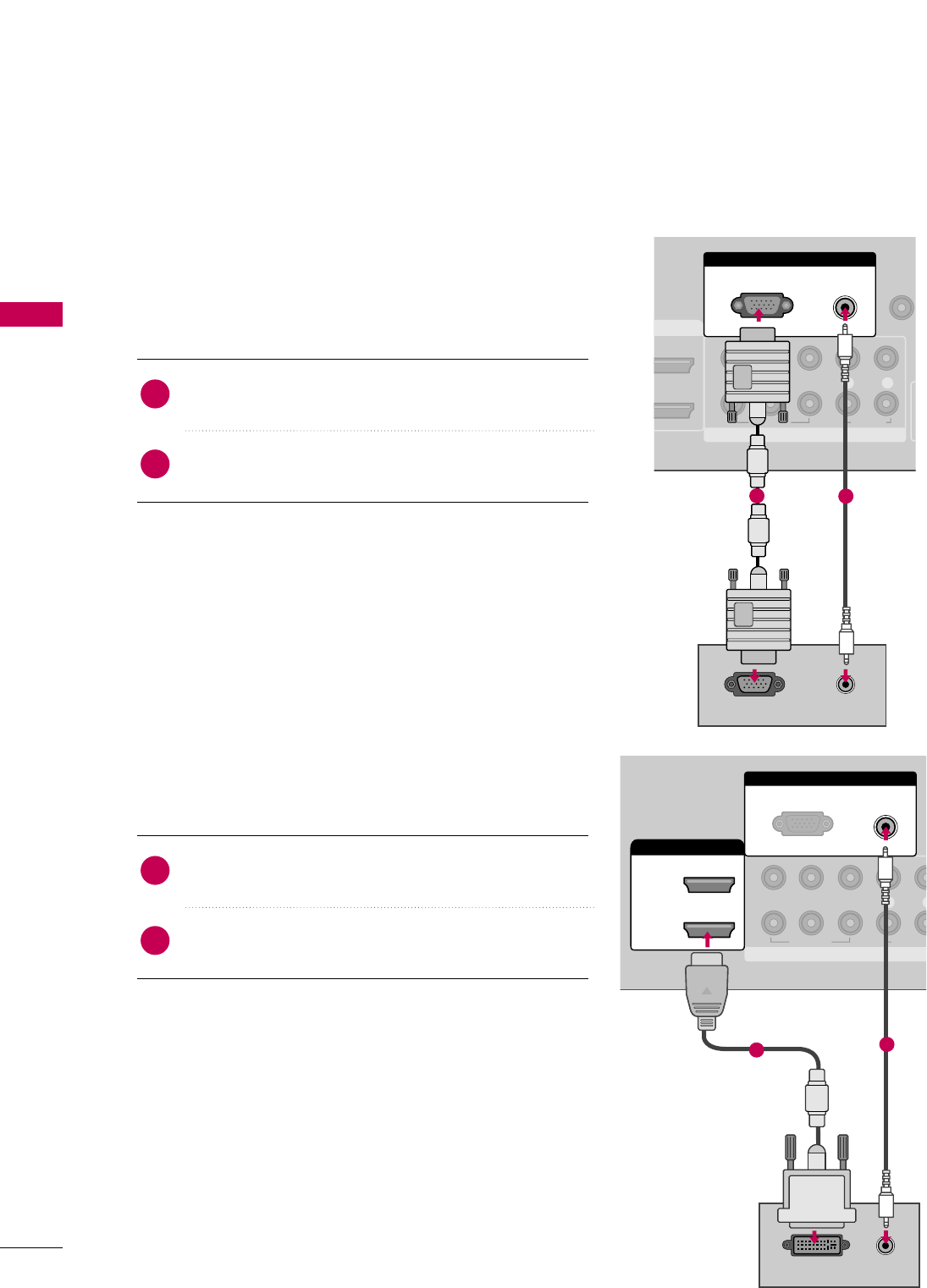
VGA (D-Sub 15 pin) Connection
COMPONENT IN
REMOT
CONTROL
1
2
(
VIDEO
LYP
BPRR
AUDIO
DVI IN
RGB IN
AUDIO
(RGB/DVI)
RGB(PC)
RGB OUTPUT AUDIO
12
Connect the VGA output of the PC to the RRGGBB
((PPCC)) jack on the TV.
Connect the PC audio output to the AAUUDDIIOO
((RRGGBB//DDVVII))jack on the TV.
1. How to connect
2. How to use
■Turn on the PC and the TV.
■Select the RRGGBB--PPCCinput source on the TV using the
IINNPPUUTTbutton on the remote control.
2
1
DVI to HDMI Connection
Connect the DVI output of the PC to the HHDDMMII//DDVVII
IINN 11, 22, or 33* jack on the TV.
Connect the PC audio output to the AAUUDDIIOO
((RRGGBB//DDVVII)) jack on the TV.
1. How to connect
2. How to use
■Turn on the PC and the TV.
■Select the HHDDMMII11, HHDDMMII22, or HHDDMMII33* input source on
the TV using the IINNPPUUTTbutton on the remote control.
2
1
COMPONENT IN
R
CO
1
2
VIDEO
LYP
BPRR
AUDIO
HDMI/DVI IN
2
1
RGB IN
AUDIO
(RGB/DVI)
RGB(PC)
DVI-PC OUTPUT AUDIO
12
* HDMI 3: Except 42/47/52LG50DC
EXTERNAL EQUIPMENT SETUP
27
Supported Display Specifications (RGB-PC, HDMI-PC)
Resolution
720x400
640x350
640x480
1920x1080
HDMI-PC
Horizontal Vertical
Frequency(KHz)Frequency(Hz)
31.468 70.09
31.469 70.08
31.469 59.94
35.156 56.25
37.879 60.31
48.363 60.00
56.476 70.06
47.776 59.87
63.981 60.02
47.712 60.015
75.00 60.00
66.587 59.934
67.5 60.00
GGTo get the the best picture quality, adjust the PC
graphics card to 1920x1080.
GGDepending on the graphics card, DOS mode may
not work if a HDMI to DVI Cable is in use.
GGIn PC mode, there may be noise associated with
the resolution, vertical pattern, contrast or bright-
ness. If noise is present, change the PC output to
another resolution, change the refresh rate to
another rate or adjust the brightness and contrast
on the PICTURE menu until the picture is clear.
GGAvoid keeping a fixed image on the screen for a
long period of time. The fixed image could
become permanently imprinted on the screen.
GGThe synchronization input form for Horizontal and
Vertical frequencies is separate.
GGDepending on the graphics card, some resolution
settings may not allow the image to be posi-
tioned on the screen properly.
GGIf there are overscan in HDMI-PC 1920x1080,
change aspect ratio to JJuusstt ssccaann.
NOTES
!
800x600
1024x768
1280x768
1280x1024
1360x768
1600x1200
1920x1080
RGB-PC
EXTERNAL EQUIPMENT SETUP
28
EXTERNAL EQUIPMENT SETUP
Screen Setup for PC mode
Selecting Resolution
You can choose the resolution in RGB-PC mode.
The PPoossiittiioonn, PPhhaassee, and SSiizzeecan also be adjusted.
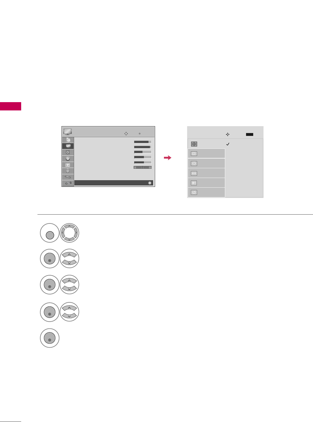
Select PPIICCTTUURREE.
Select SSccrreeeenn ((RRGGBB--PPCC)).
Select RReessoolluuttiioonn.
Select the desired resolution.
1024 x 768
1280 x 768
1360 x 768
Auto config.
Resolution
G
Position
Size
Phase
Reset
SCREEN
Move
Prev.
MENU
1
MENU
3
4
2
ENTER
ENTER
ENTER
5
ENTER
Enter
Move
PICTURE
RG
• Backlight 80
• Contrast 90
• Brightness 50
• Sharpness 60
• Color 60
• Tint 0
• Advanced Control
• Reset
Screen (RGB-PC)
E
EXTERNAL EQUIPMENT SETUP
29
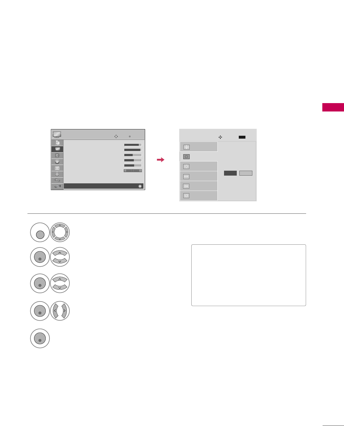
Auto Configure
Automatically adjusts picture position and minimizes image instability. After adjustment, if the image is still
not correct, try using the manual settings or a different resolution or refresh rate on the PC.
Select SSccrreeeenn ((RRGGBB--PPCC)).
Select AAuuttoo ccoonnffiigg...
Auto config. G
Resolution
Position
Size
Phase
Reset
SCREEN
Move
Prev.
MENU
To Set
3
2
ENTER
ENTER
Select YYeess.
4
ENTER
Start Auto Configuration.
5
ENTER
Select PPIICCTTUURREE.
1
MENU
• If the position of the image is still not
correct, try Auto adjustment again.
• If picture needs to be adjusted again
after Auto adjustment in RGB-PC, you
can adjust the PPoossiittiioonn, SSiizzee or
PPhhaassee.
Yes No
Enter
Move
PICTURE
RG
• Backlight 80
• Contrast 90
• Brightness 50
• Sharpness 60
• Color 60
• Tint 0
• Advanced Control
• Reset
Screen (RGB-PC)
E
EXTERNAL EQUIPMENT SETUP
30
EXTERNAL EQUIPMENT SETUP
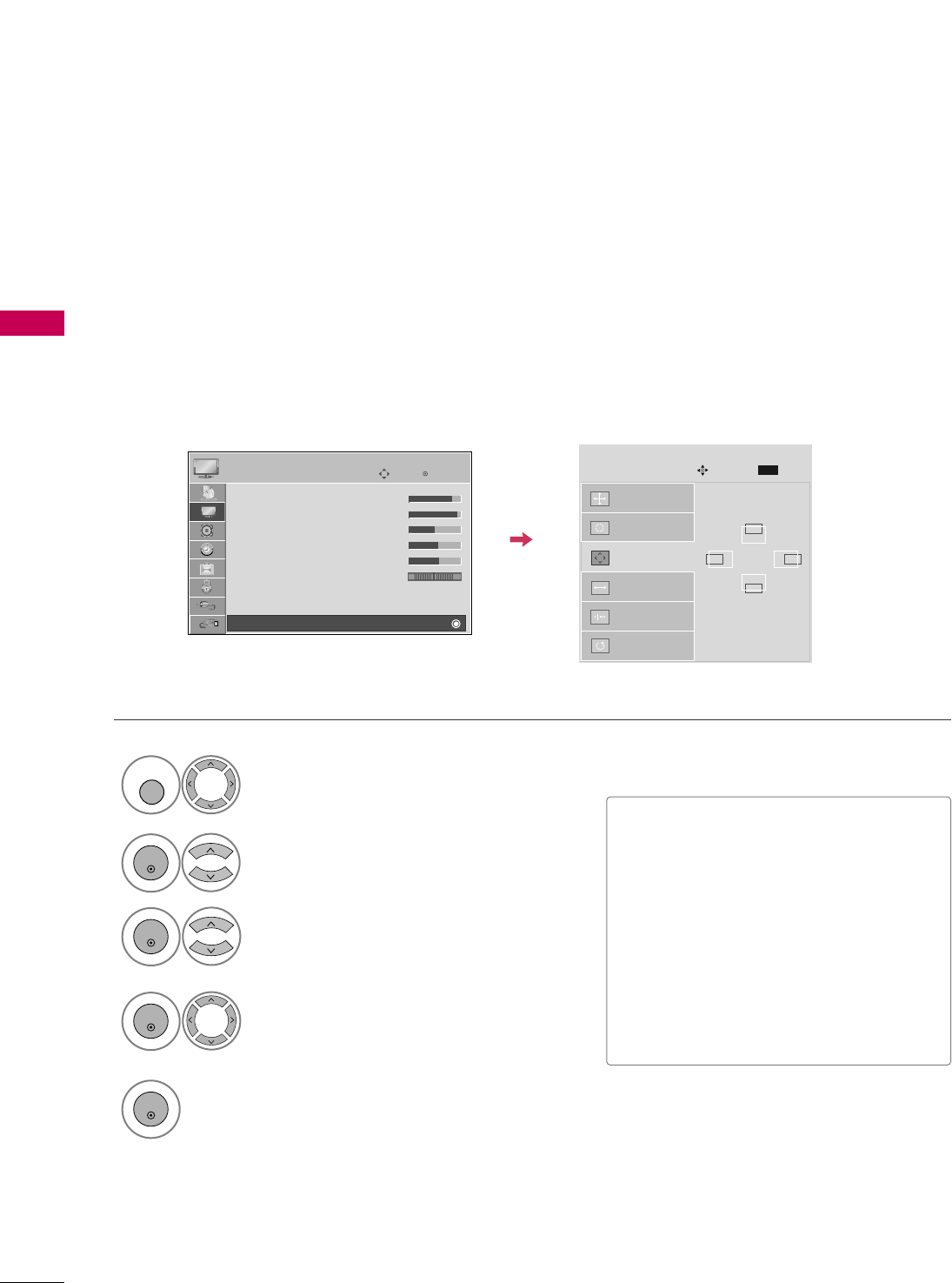
Adjustment for screen Position, Size, and Phase
If the picture is not clear after auto adjustment and especially if characters are still trembling, adjust the picture
phase manually.
This feature operates only in RGB-PC mode.
Select PPoossiittiioonn, SSiizzee, or PPhhaassee.
Make appropriate adjustments.
Auto config.
Resolution
Position
G
Size
Phase
Reset
GF
D
E
SCREEN
Move
Prev.
MENU
3
ENTER
4
ENTER
■PPoossiittiioonn: This function is to adjust pic-
ture to left/right and up/down as you
prefer.
■SSiizzee: This function is to minimize any
vertical bars or stripes visible on the
screen background. And the horizontal
screen size will also change.
■PPhhaassee: This function allows you to
remove any horizontal noise and clear or
sharpen the image of characters.
Select PPIICCTTUURREE.
Select SSccrreeeenn ((RRGGBB--PPCC)).
1
MENU
2
ENTER
5
ENTER
Enter
Move
PICTURE
RG
• Backlight 80
• Contrast 90
• Brightness 50
• Sharpness 60
• Color 60
• Tint 0
• Advanced Control
• Reset
Screen (RGB-PC)
E
EXTERNAL EQUIPMENT SETUP
31
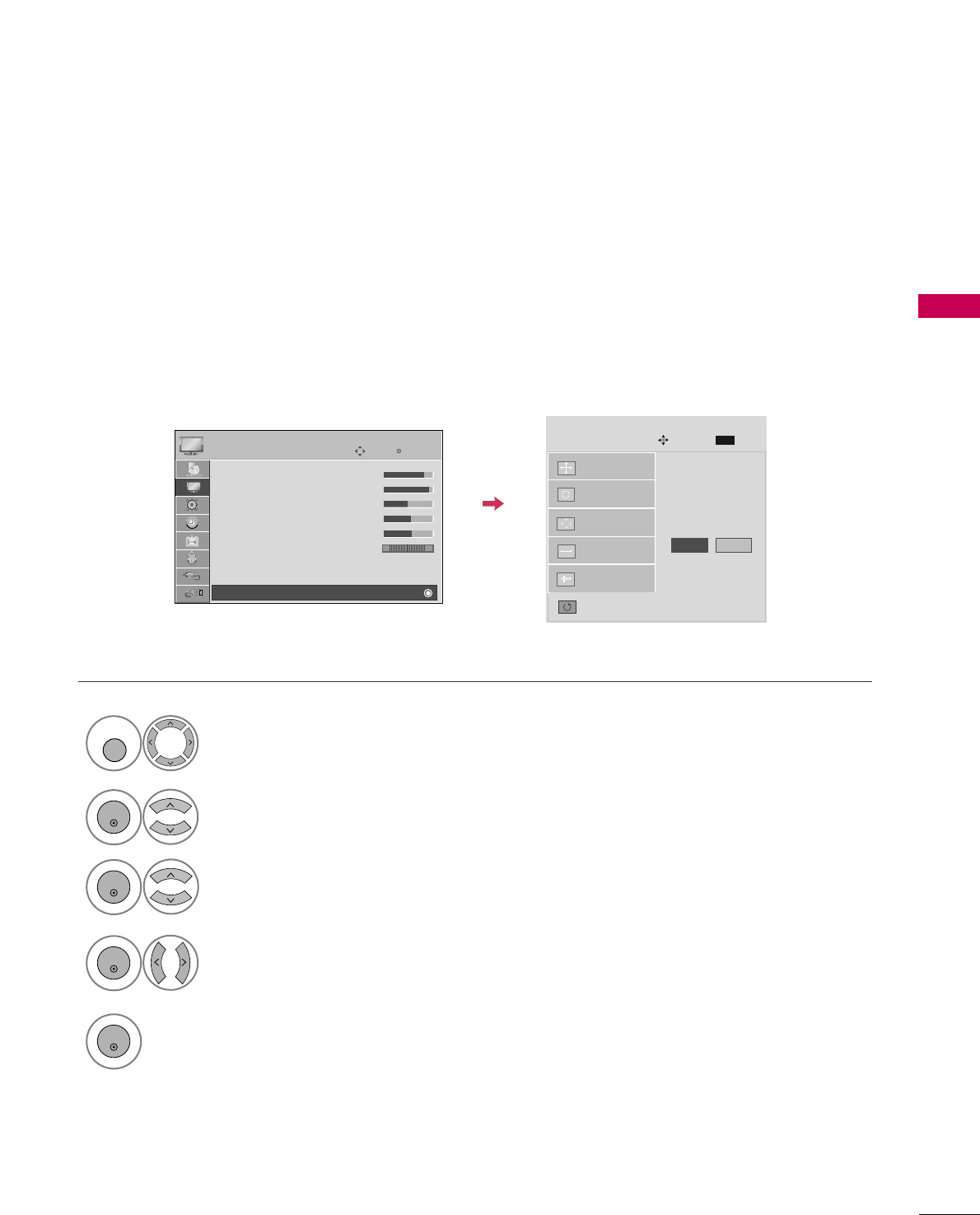
Screen Reset (Reset to original factory values)
Returns PPoossiittiioonn, SSiizzee, and PPhhaasseeto the default factory settings.
This feature operates only in RGB-PC mode.
Auto config.
Position
Resolution
Size
Phase
Reset
G
SCREEN
Move
Prev.
MENU
To Set
Select RReesseett.
3
ENTER
Select PPIICCTTUURREE.
Select SSccrreeeenn ((RRGGBB--PPCC)).
1
MENU
2
ENTER
Select YYeess.
4
ENTER
5
ENTER
Yes No
Enter
Move
PICTURE
RG
• Backlight 80
• Contrast 90
• Brightness 50
• Sharpness 60
• Color 60
• Tint 0
• Advanced Control
• Reset
Screen (RGB-PC)
E
EXTERNAL EQUIPMENT SETUP
32
USB CONNECTION
EXTERNAL EQUIPMENT SETUP
AV IN 2
L/MONO
R
AUDIO
VIDEO
HDMI IN 3 USB IN
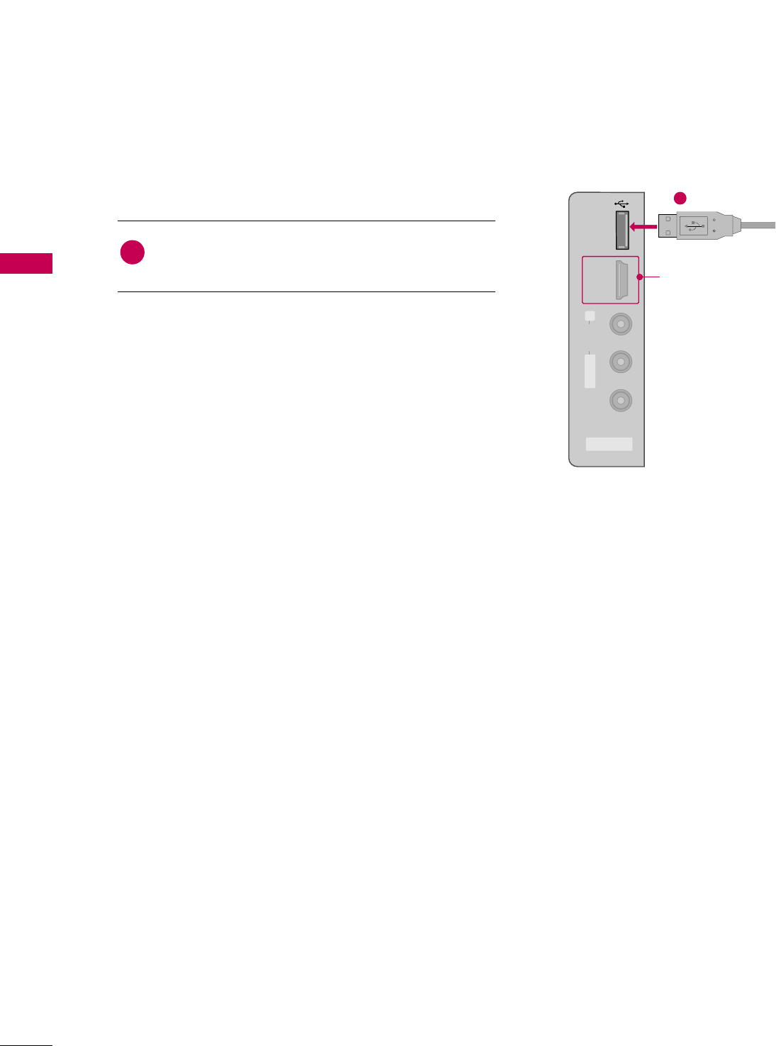
Connect the USB device to the UUSSBB IINNjack on the side
of TV.
1. How to connect
1
2. How to use
■After connecting the UUSSBB IINNjack, you use the USB function.
(GGpp..4488)
1
(Except 42/47/52LG50DC)
EXTERNAL EQUIPMENT SETUP
33
AUDIO OUT CONNECTION
Send the TV’s audio to external audio equipment via the Audio Output port.
IN
GB/DVI)
RS-232C IN
(CONTROL & SERVICE)
L R
AUDIO
L R
AUDIO
AUDIO OUT
AV IN 1
VIDEO L R
(MONO)
AUDIO
S-VIDEO
1
IO
DVI)
REMOTE
CONTROL IN
ANTENNA/
CABLE IN
RS-232C IN
(CONTROL & SERVICE)
R
AUDIO
OPTICAL COAXIAL
DIGITAL AUDIO OUT
AV IN 1
VIDEO L R
(MONO)
AUDIO
S-VIDEO
AUDIO OUT
1
2
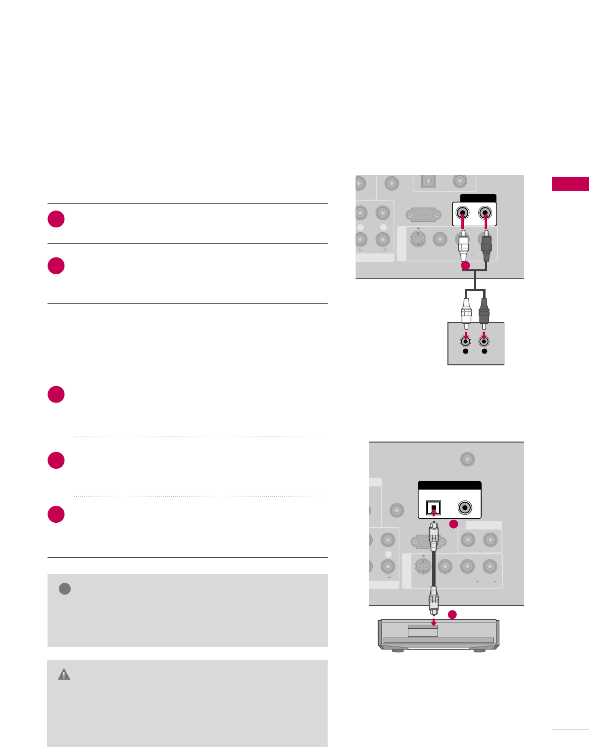
GGWhen connecting with external audio equipments, such as
amplifiers or speakers, you can turn the TV speakers off in
the menu. (GG pp..7733)
NOTE
!
GDo not look into the optical output port. Looking at the
laser beam may damage your vision.
GGBlock the SPDIF out (optical/coaxial) about the contents
with ACP(Audio Copy Protection) function.
CAUTION
Connect one end of the optical or coaxial cable to the
TV’s OOPPTTIICCAALL or CCOOAAXXIIAALLport of DDIIGGIITTAALL AAUUDDIIOO
OOUUTT.
Connect the other end of the optical or coaxial cable to
the digital audio input on the audio equipment.
Set the “TV Speaker option - Off” in the AUDIO menu. (GG
pp..7733). See the external audio equipment instruction man-
ual for operation.
1. How to connect
2
3
1
Connect audio outputs to the TV’s AAUUDDIIOO OOUUTTjacks.
Set the “TV Speaker option - Off” in the AUDIO menu.
(GGpp..7733). See the external audio equipment instruction
manual for operation.
1. How to connect
2
1
Analog
Digital
USB
48
USB
ENTRY MODES
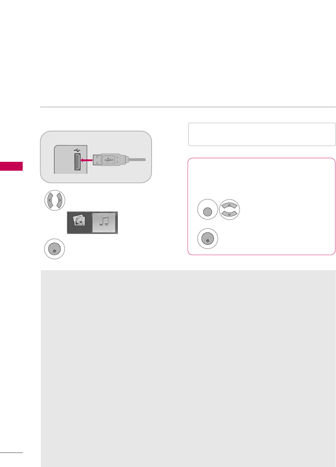
When you connect a USB device, this screen is displayed automatically.
In USB device, you can not add a new folder or delete the existing folder.
Precautions when using the USB device
GGOnly a USB storage device is recognizable.
GGIf the USB storage device is connected through a
USB hub, the device is not recognizable.
GGA USB storage device using an automatic recogni-
tion program may not be recognized.
GGA USB storage device which uses its own driver
may not be recognized.
GGUSB multi-card reader or USB hard drive may not
operate smoothly or may not operate at all.
GGThe recognition speed of a USB storage device
may depend on each device.
GGPlease do not turn off the TV or unplug the USB
device when the connected USB storage device is
working. When such device is suddenly separated
or unplugged, the stored files or the USB storage
device may be damaged.
GGPlease do not connect the USB storage device
which was artificially maneuvered on the PC. The
device may cause the product to malfunction or
fail to be played. Never forget to use only a USB
storage device which has normal music files or
image files.
GGPlease use only a USB storage device which was
formatted as a FAT or NTFS file system provided
with the Windows operating system. In case of a
storage device formatted as a different utility pro-
gram which is not supported by Windows, it may
not be recognized.
GGPlease connect power to a USB storage device
which requires an external power supply. If not,
the device may not be recognized.
GGPlease connect a USB storage device with cable is
offered by USB maker. If connected with cable is
not offered by USB maker or an excessively long
cable, the device may not be recognized.
GGSome USB storage devices may not be supported
or operated smoothly.
GGBecause the TV doesn’t support file sorting for
USB storage device, the file on the storage device
will be displayed in the order saved.
GGPlease backup important files because data on
USB device may be damaged. Data management is
consumer's responsibility and as a result, the man-
ufacturer does not cover data damage.
When removing the USB device
Connect the USB device to the UUSSBB IINN
jacks on the side of TV.
3
Select PPhhoottoo LLiisstt or MMuussiiccLLiisstt.
1
USB IN
Photo List Music List
Select UUSSBB EEjjeecctt.
Select the UUSSBB EEjjeeccttmenu before removing the
USB device.
2
ENTER
1
Q. MENU
2
ENTER
■It doesn’t support USB HDD
■This TV supports JPG and MP3.
USB
50
USB
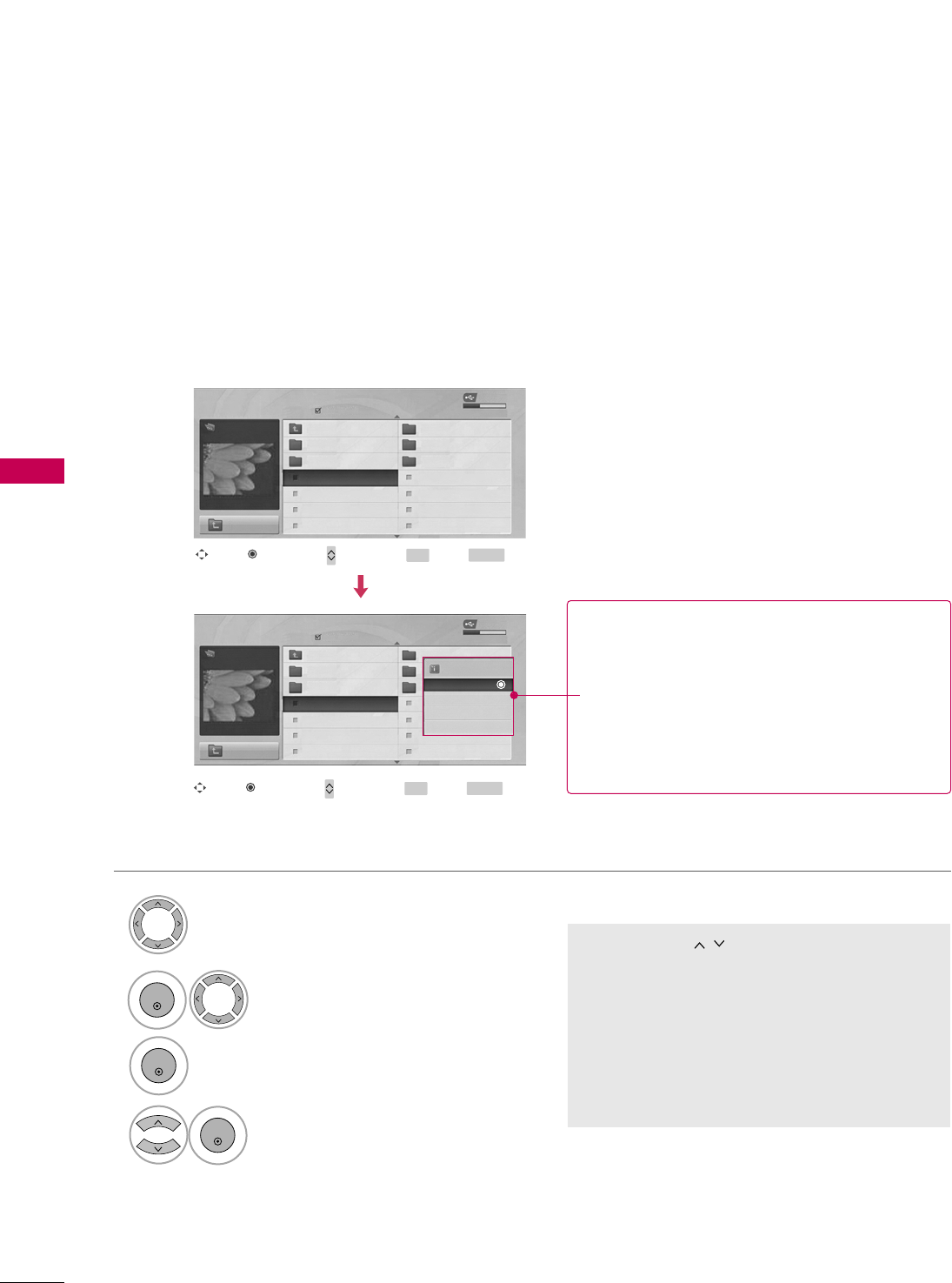
Photo Selection and Popup Menu
Select the target folder or drive.
Select the desired photos.
2
Show the Popup menu.
3
1
■Use the CCHH button to navigation in the
photo page.
■Use the FFAAVVbutton to mark or unmark a
photo. When one or more photos are marked,
you can view individual photos or a slide show
of the marked photos. If no photos are marked,
you can view all photos individually or all pho-
tos in the folder in a slide show.
4Select the desired Popup menu.
ENTER
ENTER
ENTER
When you select a file (not folder), this PopUp
menu is displayed.
GGVViieeww: Display the selected item.
GGMMaarrkk AAllll: Mark all photos on the screen.
GGUUnnmmaarrkk AAllll: Deselect all marked photos.
GGDDeelleettee: Delete the selected photo item.
GGCClloossee: Close the pop-up menu.
USB Device
Page 2/3
No Marked
Photo List
Upper
Free Space 150MB
1366x768, 125KB
KY101 06/10/2008
KY102 04/03/2008
JMJ001 01/01/2000
JMJ002 06/15/2008
JMJ003 04/03/2008
JMJ004 02/18/2008
KY103 03/30/2008
KY104 06/19/2008
KY105 01/31/2008
JMJ005 05/13/2008
JMJ006 05/26/2008
JMJ007 02/18/2008
JMJ008 02/18/2008
Upper
Drive1
Drive1
JMJ001
JMJ001
Move Move Page Mark Exit
CH FAV RETURN
PopUp Menu
Move Move Page Mark Exit
CH FAV RETURN
PopUp Menu
1366x768
125KB
View
Mark All
Delete
Close
USB
52
USB
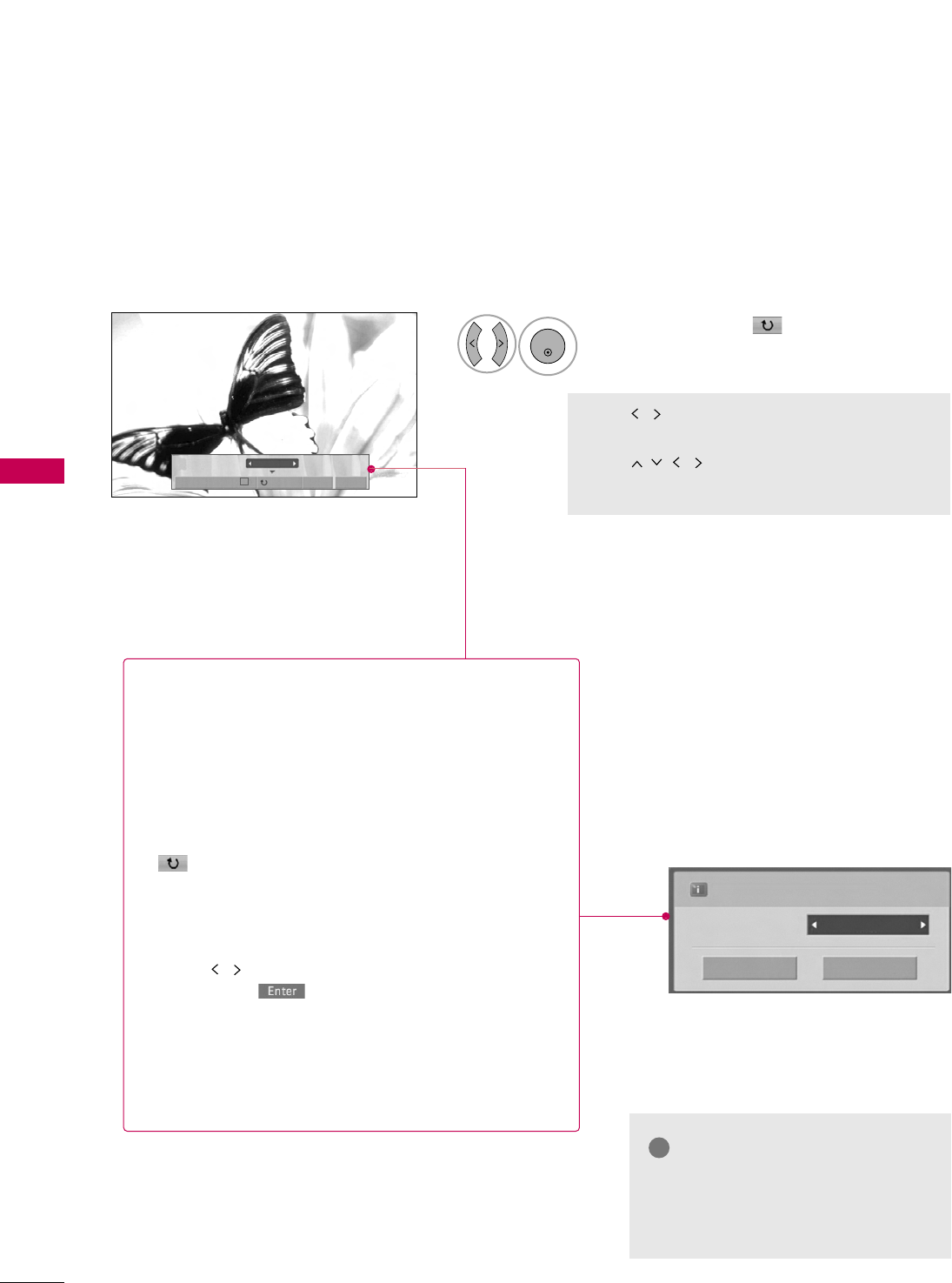
Select the SSiiddee SShhooww, ((RRoottaattee)),
DDeelleettee,OOppttiioonn, or HHiiddee..
■Use button to select the previous or
next photo.
■Use button to select and control
the menu on the full-sized screen.
ENTER
6
NOTE
!
GGThis TV will not be able to decode
most JPG images saved using the
Progressive option.
1/17
Slide Show Delete Option Hide
Press FF GGto set the time interval between
slides.
Slide Speed Fast
Cancel
Enter
GGSSlliiddee SShhooww: Selected photos are displayed during the
slide show. If no photo is selected, all photos in the cur-
rent folder are displayed during slide show.
■Set the time interval of the slide show in OOppttiioonn.
■A slide show continues for a maximum of 4 hours.
After 4 hours, the slide show will end and go to TV
mode or external input mode.
GG((RRoottaattee)): Rotate photos.
■Rotates the photo 90°, 18 0 °, 270°, 360°clockwise.
GGDDeelleettee: Delete photos.
GGOOppttiioonn: Set values for SSlliiddee SSppeeeedd.
■Use button and EENNTTEERRbutton to set values.
Then go to and press EENNTTEERRto save the set-
tings.
GGHHiiddee : Hide the menu on the full-sized screen.
■To see the menu again on the full-sized screen, press
EENNTTEERR button to display.
GG
USB
54
USB
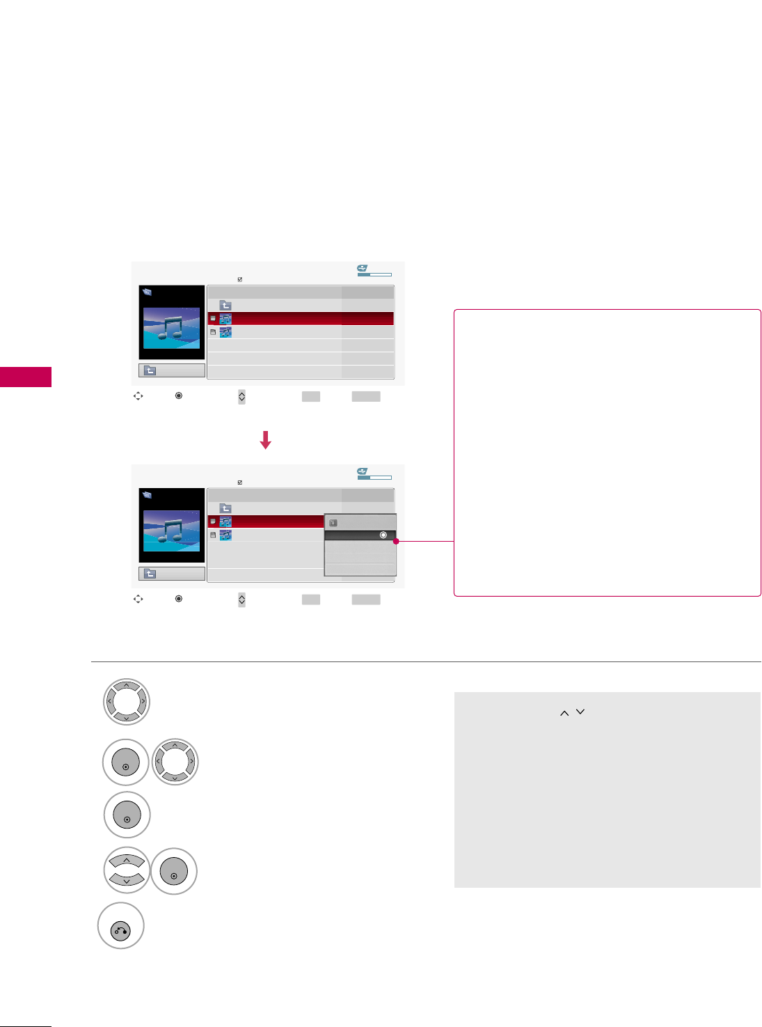
Music Selection and Popup Menu
■Use the CCHH button to navigation in
the music page.
■Use FFAAVVbutton to mark or unmark a music
file. If no music is marked, all the music in the
folder will be played in sequence. When one or
more music files are marked, the marked music
files will be played in sequence. If you want to
listen to only one song repeatedly, just mark
that one file and play.
Up to 6 music titles are listed per page.
Select the target folder or drive.
Select the desired musics.
Show the Popup menu.
Select the desired Popup menu.
2
3
1
4
ENTER
ENTER
ENTER
5
RETURN
Return to TV viewing
USB Device
Page 1/1
No Marked
Music List
Upper
Free Space 150MB
3945 KB, 128 Kbps
Drive1
Arirang
Move Move Page Mark Exit
CH FAV RETURN
PopUp Menu
Play TimeTitle
Upper
Good Bye
Arirang
USB Device
Page 1/1
No Marked
Music List
Upper
Free Space 150MB
3945 KB, 128 Kbps
Drive1
Arirang
Move Move Page Mark Exit
CH FAV RETURN
PopUp Menu
Play TimeTitle
Upper
Good Bye
Arirang
05:30
04:12
3945 KB
128 Kbps
Play
Mark All
Delete
Close
GGPPllaayy (During stop): Play the selected music.
Once a song finishes playing, the next selected
one will be played. When there are no selected
musics to play, the next one in the current fold-
er will be played. If you go to a different folder
and press the EENNTTEERRbutton, the current
music in playback will stop.
GGSSttoopp PPllaayy (During playback): Stop the play-
ing musics.
GGMMaarrkk AAllll: Mark all musics in the folder.
GGUUnnmmaarrkk AAllll: Deselect all marked music.
GGDDeelleettee: Delete the selected music.
GGCClloossee: Close the pop-up menu.
USB
55
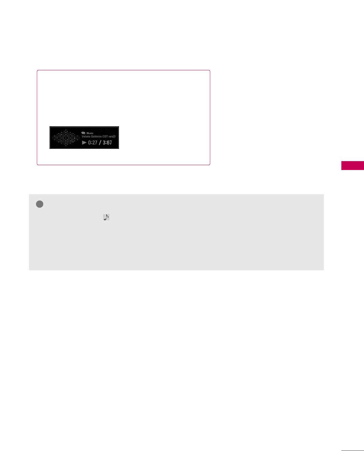
■The play information box (as shown below) will automatically
move across the screen when there is no user input to pre-
vent a fixed image remaining on the screen for a extended
period of time.
NOTE
!
GGWhen music is playing, is displayed in front of the music play time.
GGA damaged or corrupted music file that does not play displays 00:00 as the play time.
GGMusic files with copy-protection will not play.
GGPress EENNTTEERR, AA, or RREETTUURRNN button to stop the screen saver.
GGThis TV can not play music files less than 16 Kbytes.
APPENDIX
98
APPENDIX
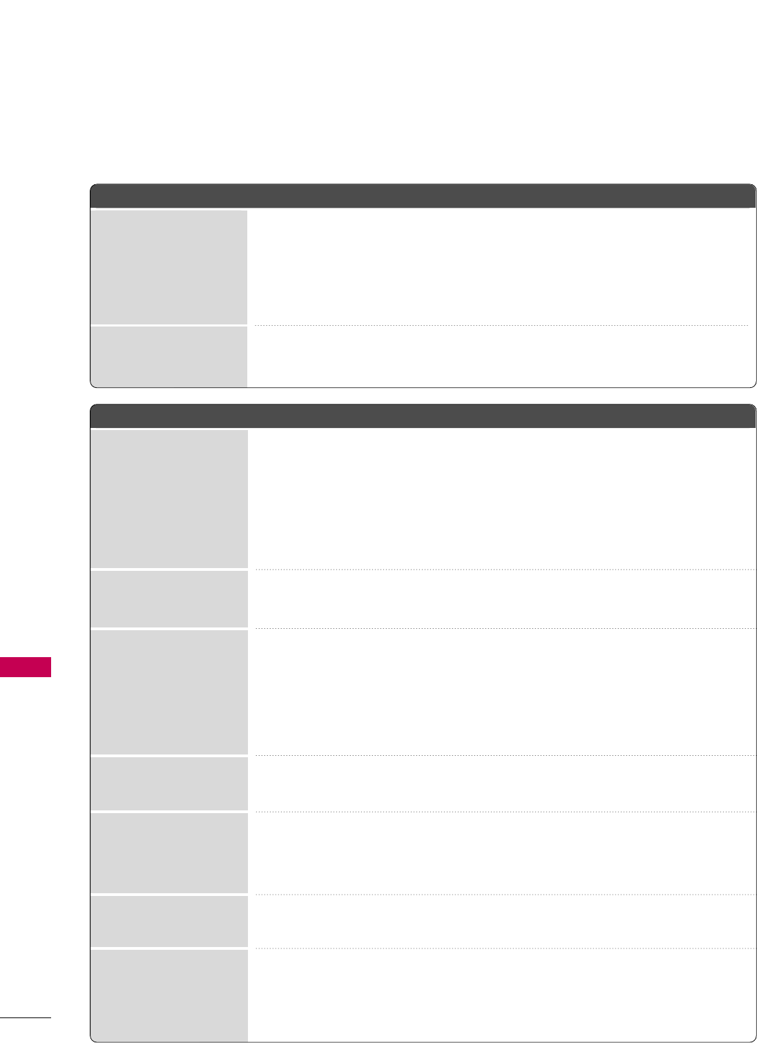
TROUBLESHOOTING
TThhee ooppeerraattiioonn ddooeess nnoott wwoorrkk nnoorrmmaallllyy..
TThhee vviiddeeoo ffuunnccttiioonn ddooeess nnoott wwoorrkk..
No picture &No sound
No or poor color
or poor picture
Poor reception on
some channels
Lines or streaks
in pictures
No picture
when connecting HDMI
Horizontal/vertical bars
or picture shaking
Picture appears slowly
after switching on
The remote control
doesn’t work
Power is suddenly
turned off
■Check to see if there is any object between the product and the remote control
causing obstruction. Ensure you are pointing the remote control directly at the TV.
■Ensure that the batteries are installed with correct polarity (+ to +, - to -).
■Ensure that the correct remote operating mode is set: TV, VCR etc.
■Install new batteries.
■Is the sleep timer set?
■Check the power control settings. Power interrupted.
■Check whether the product is turned on.
■Try another channel. The problem may be with the broadcast.
■Is the power cord inserted into wall power outlet?
■Check your antenna direction and/or location.
■Test the wall power outlet, plug another product’s power cord into the outlet
where the product’s power cord was plugged in.
■This is normal, the image is muted during the product startup process. Please
contact your service center, if the picture has not appeared after five minutes.
■Adjust Color in menu option.
■Keep a sufficient distance between the product and the VCR.
■Try another channel. The problem may be with the broadcast.
■Are the video cables installed properly?
■Activate any function to restore the brightness of the picture.
■Check for local interference such as an electrical appliance or power tool.
■Station or cable product experiencing problems, tune to another station.
■Station signal is weak, reorient antenna to receive weaker station.
■Check for sources of possible interference.
■Check antenna (Change the direction of the antenna).
■Check HDMI cable over version 1.3.
The HDMI cables don’t support HDMI version 1.3, it cause flickers or no screen
display. In this case use the latest cables that support HDMI version 1.3.
APPENDIX
99
TThheerree iiss aa pprroobblleemm iinn PPCC mmooddee.. ((OOnnllyy PPCC mmooddee aapppplliieedd))
■Adjust resolution, horizontal frequency, or vertical frequency.
■Check the input source.
■Work the Auto configure or adjust clock, phase, or H/V position. (Option)
■Check the signal cable.
■Reinstall the PC video card.
The signal is out of range
Screen color is unstable
or single color
Vertical bar or stripe on
background &
Horizontal Noise &
Incorrect position
Picture OK & No sound
Unusual sound from
inside the product
No sound
when connecting
HDMI/USB
No output from one
of the speakers
TThhee aauuddiioo ffuunnccttiioonn ddooeess nnoott wwoorrkk..
■Press the VOL or VOLUME button.
■Sound muted? Press MUTE button.
■Try another channel. The problem may be with the broadcast.
■Are the audio cables installed properly?
■Adjust Balance in menu option.
■A change in ambient humidity or temperature may result in an unusual noise
when the product is turned on or off and does not indicate a fault with the
product.
■Check HDMI cable over version 1.3.
■Check USB cable over version 2.0.
■Use normal MP3 file.

APPENDIX
100
APPENDIX
MAINTENANCE
Early malfunctions can be prevented. Careful and regular cleaning can extend the amount of time you can
enjoy your new TV.
Caution: Be sure to turn the power off and unplug the power cord before you begin any cleaning.
Cleaning the Screen
Here’s a great way to keep the dust off your screen for a while. Wet a soft cloth in a mixture of lukewarm
water and a little fabric softener or dish washing detergent. Wring the cloth until it’s almost dry, and then
use it to wipe the screen.
Make sure the excess water is off the screen, and then let it air-dry before you turn on your TV.
Cleaning the Cabinet
■To remove dirt or dust, wipe the cabinet with a soft, dry, lint-free cloth.
■Please be sure not to use a wet cloth.
Extended Absence
GG If you expect to leave your TV dormant for a long time (such as a vacation), it’s a good idea to unplug
the power cord to protect against possible damage from lightning or power surges.
CAUTION
2
1
APPENDIX
101
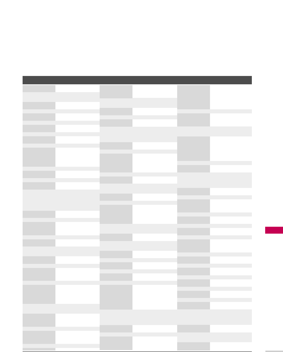
PRODUCT SPECIFICATIONS
■The specifications shown above may be changed without prior notice for quality improvement.
MODELS
AC100-240V ~ 50/60Hz
NTSC-M, ATSC, 64 & 256 QAM
VHF 2-13, UHF 14-69, CATV 1-135, DTV 2-69, CADTV 1-135
75 ohm
32 ~ 104°F (0 ~40°C)
Less than 80%
-4 ~ 140°F (-20 ~60°C)
Less than 85%
Dimensions
(Width x Height
x Depth)
Weight
Power requirement
Television System
Program Coverage
External Antenna Impedance
Environment
condition
With stand
Without stand
With stand
Without stand
Operating Temperature
Operating Humidity
Storage Temperature
Storage Humidity
37LH50
(37LH50-UC)
42LH50 (42LH50-UC)
42LG50DC (42LG50DC-UG)
42LG55 (42LG55-UE)
36.8 x 26.9 x 11.5 inches
936.4 x 685.4 x 293.4 mm
36.8 x 24.1 x 3.4 inches
936.4 x 612.8 x 88.0 mm
40.3 pounds / 18.3 kg
34.3 pounds / 15.6 kg
40.7 x 28.9 x 11.5 inches
1034.0 x 735.0 x 294.0 mm
40.7 x 26.1 x 3.5 inches
1034.0 x 663.0 x 91.0 mm
54.0 pounds / 24.5 kg
48.5 pounds / 22.0 kg
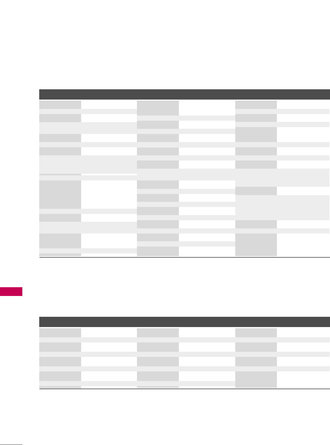
MODELS 47LH50(47LH50-UC)
47LG50DC (47LG50DC-UG)
47LG55 (47LG55-UE)
52LH50(52LH50-UC)
52LG50DC (52LG50DC-UG)
Dimensions
(Width x Height
x Depth)
Weight
With stand
Without stand
With stand
Without stand
45.5 x 32.0 x 13.5 inches
1156.2 x 813.1 x 342.9 mm
45.5 x 29.1 x 4.0 inches
1156.2 x 739.2 x 103.0 mm
64.3 pounds / 29.2 kg
54.2 pounds / 24.6 kg
50.8 x 35.1 x 13.5 inches
1291.7 x 892.2 x 342.9 mm
50.8 x 32.1 x 4.5 inches
1291.7 x 817.0 x 115.3 mm
87.0 pounds / 39.5 kg
76.9 pounds / 34.9 kg

APPENDIX
102
PROGRAMMING THE REMOTE CONTROL
APPENDIX
The provided universal remote control can be programmed to operate most remote-controllable devices.
Note that the remote may not control all models of other brands.
Programming a code into a remote mode
Testing your remote control.
To find out whether your remote control can operate other components without programming, turn on a
component such as a STB and press the corresponding mode button (such as a SSTTBB) on the remote con-
trol, while pointing at the component. Test the PPOOWWEERRand CCHHbuttons to see if the component
responds correctly. If the component does not operate correctly, the remote control requires programming
to operate the device.
Turn on the component to be programmed, then press the corresponding mode button (such as SSTTBB) on
the remote control. The remote control button of the desired device is illuminated.
Press the MMEENNUUand MMUUTTEEbuttons simultaneously, and the remote control is ready to be programmed with
the code.
Enter a code number using the number buttons on the remote control. Programming code numbers for the
corresponding component can be found on the following pages. If the code is correct, the device will turn
off.
Press the MMEENNUUbutton to store the code.
Test the remote control functions to see if the component responds correctly. If not, repeat from step 2.
2
3
4
5
6
1
APPENDIX
103
Remote Control Code
Brand Codes Brand Codes Brand Codes
AIWA 034
AKAI 016 043 046 124
125 146
AMPRO 072
ANAM 031 033 103
AUDIO DYNAMICS
012 023 039 043
BROKSONIC 035 037 129
CANON 028 031 033
CAPEHART 108
CRAIG 003 040 135
CURTIS MATHES 031 033 041
DAEWOO 005 007 010 064
065 108 110 111
112 116 117 119
DAYTRON 108
DBX 012 023 039 043
DYNATECH 034 053
ELECTROHOME 059
EMERSON 006 017 025 027
029 031 034 035
036 037 046 101
129 131 138 153
FISHER 003 008 009 010
FUNAI 034
GE 031 033 063 072
107 109 144 147
GO VIDEO 132 136
HARMAN KARDON 012 045
HITACHI 004 018 026 034
043 063 137 150
INSTANTREPLAY 031 033
JCL 031 033
JCPENNY 012 013 015 033
040 066 101
JENSEN 043
JVC 012 031 033 043
048 050 055 060
130 150 152
KENWOOD 014 034 039 043
047 048
LG (GOLDSTAR) 001 012 013 020
101 10 6 114 123
LLOYD 034
LXI 003 009 013 014
017 034 101 106
MAGIN 040
MAGNAVOX 031 033 034 041
067 068
MARANTZ 012 031 033 067
069
MARTA 101
MATSUI 027 030
MEI 031 033
MEMOREX 003 010 014 031
033 034 053 072
101 102 134 139
MGA 045 046 059
MINOLTA 013 020
MITSUBISHI 013 020 045 046
049 051 059 061
151
MTC 034 040
MULTITECH 024 034
NEC 012 023 039 043
048
NORDMENDE 043
OPTONICA 053 054
PANASONIC 066 070 074 083
133 140 145
PENTAX 013 020 031 033
063
PHILCO 031 034 067
PHILIPS 031 033 034 054
067 071 101
PILOT 101
PIONEER 013 021 048
PORTLAND 108
PULSAR 072
QUARTZ 011 014
QUASAR 033 066 075 145
RCA 013 020 033 034
040 041 062 063
107 109 140 144
145 147
REALISTIC 003 008 010 014
031 033 034 040
053 054 101
RICO 058
RUNCO 148
SALORA 014
SAMSUNG 032 040 102 104
105 107 109 112
113 115 120 122
125
SANSUI 022 043 048 135
SANYO 003 007 010 014
102 134
SCOTT 017 037 112 129
131
SEARS 003 008 009 010
013 014 017 020
031 042 073 081
101
SHARP 031 054 149
SHINTOM 024
SONY 003 009 031 052
056 057 058 076
077 078 149
SOUNDESIGN 034
STS 013
SYLVANIA 031 033 034 059
067
SYMPHONIC 034
TANDY 010 034
TATUNG 039 043
TEAC 034 039 043
TECHNICS 031 033 070
TEKNIKA 019 031 033 034
101
THOMAS 034
TMK 006
TOSHIBA 008 013 042 047
059 082 112 131
TOTEVISION 040 101
UNITECH 040
VECTOR RESEARCH
012
VICTOR 048
VIDEO CONCEPTS
012 034 046
VIDEOSONIC 040
WARDS 003 013 017 024
031 033 034 040
053 054 131
YAMAHA 012 034 039 043
ZENITH 034 048 056
058 072 080 101
VCR
APPENDIX
104
APPENDIX
Brand Codes Brand Codes Brand Codes
ALPHASTAR DSR 123
AMPLICA 050
BIRDVIEW 051 126 129
CHANNEL MASTER
013 014 015 018
036 055
CHAPARRAL 008 009 012 077
CITOH 054
CURTIS MATHES 050 145
DRAKE 005 006 007 010
011 052 112 116
141
DX ANTENNA 024 046 056 076
ECHOSTAR 038 040 057 058
093 094 095 096
097 098 099 100
122
ELECTRO HOME 089
EUROPLUS 114
FUJITSU 017 021 022 027
133 134
GENERAL INSTRUMENT
003 004 016 029
031 059 101
HITACHI 139 140
HOUSTON TRACKER
033 037 039 051
057 104
HUGHES 068
JANIEL 060 147
JERROLD 061
KATHREIN 108
LEGEND 057
LG 001
LUTRON 132
LUXOR 062 144
MACOM 010 059 063 064
065
MEMOREX 057
NEXTWAVE 028 124 125
NORSAT 069 070
PACE SKY SATELLITE
143
PANASONIC 060 142
PANSAT 121
PERSONAL CABLE 117
PHILIPS 071
PICO 105
PRESIDENT 019 102
PRIMESTAR 030 110 111
PROSAT 072
RCA 066 106
REALISTIC 043 074
SAMSUNG 123
SATELLITE SERVICE CO
028 035 047 057
085
SCIENTIFIC ATLANTA
032 138
SONY 103
STARCAST 041
SUPER GUIDE 020 124 125
TEECOM 023 026 075 087
088 090 107 130
137
TOSHIBA 002 127
UNIDEN 016 025 042 043
044 045 048 049
078 079 080 086
101 135 136
VIEWSTAR 115
WINEGARD 128 146
ZENITH 081 082 083 084
091 120
HDSTB
DVD
Brand Codes Brand Codes Brand Codes
APEX DIGITAL 022
DENON 020 014
GE 005 006
HARMAN KARDON 027
JVC 012
LG 001 010 016 025
MAGNAVOX 013
MARANTZ 024
MITSUBISHI 002
NAD 023
ONKYO 008 017
PANASONIC 003 009
PHILIPS 013
PIONEER 004 026
PROCEED 021
PROSCAN 005 006
RCA 005 006
SAMSUNG 011 015
SONY 007
THOMPSON 005 006
TOSHIBA 019 008
YAMAHA 009 018
ZENITH 010 016 025
APPENDIX
105
IR CODES
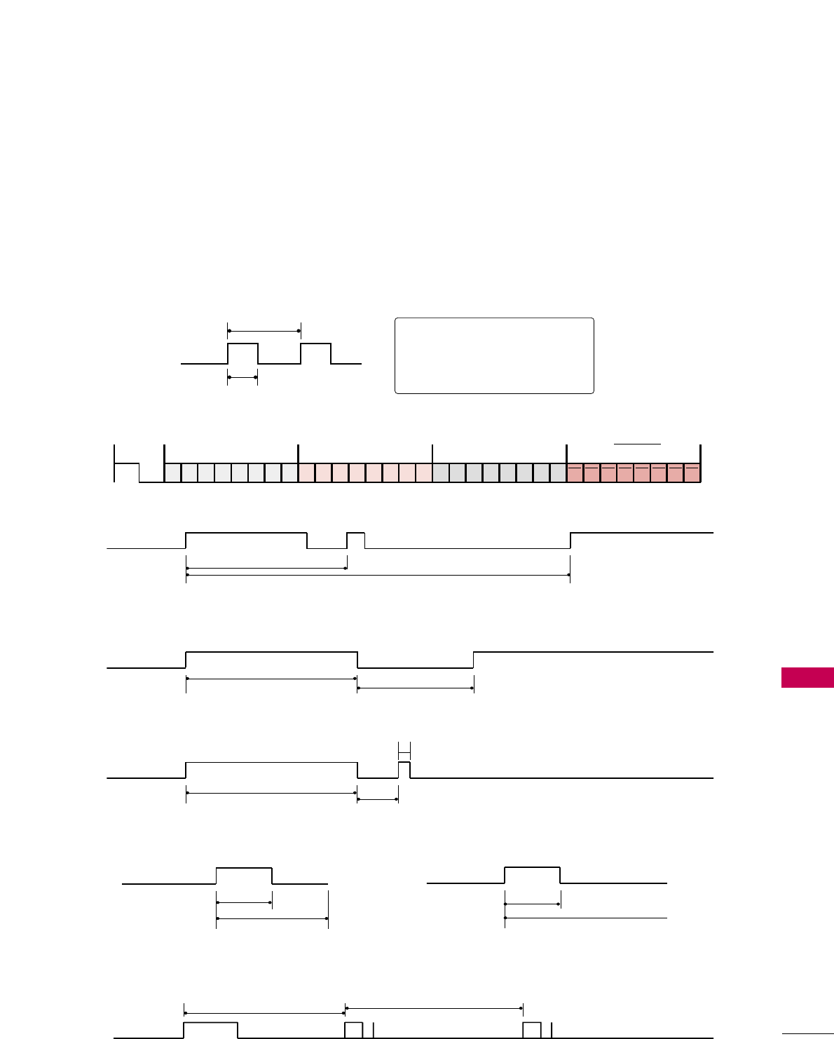
■
Configuration of frame
1st frame
Repeat frame
■
Lead code
■
Repeat code
■BBiitt ddeessccrriippttiioonn
■FFrraammee iinntteerrvvaall:: TTff
The waveform is transmitted as long as a key is depressed.
C0 C1 C2 C3 C4 C5 C6 C7 C0 C1 C2 C3 C4 C5 C6 C7 D0 D1 D2 D3 D4 D5 D6 D7 D0 D1 D2 D3 D4 D5 D6 D7
Lead code Low custom code High custom code Data code Data code
Repeat code Tf
4.5 ms
9 ms
2.25 ms
9 ms
0.55 ms
0.56 ms
1.12 ms
0.56 ms
2.24 ms
Tf Tf
Tf=108ms @455KHz
Bit ”0” Bit ”1”
1. How to Connect
■Connect your wired remote control to the Remote Control port on the TV.
2. Remote Control IR Codes
■
Output waveform
Single pulse, modulated with 37.917KHz signal at 455KHz
T1
Tc
Carrier frequency
FCAR = 1/TC = fOSC/12
Duty ratio = T1/TC = 1/3
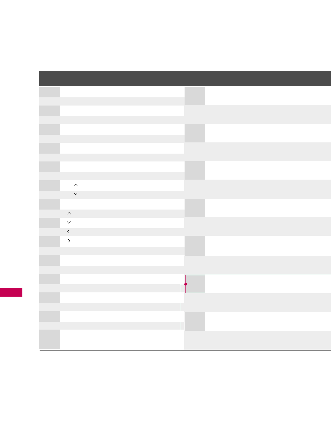
APPENDIX
106
APPENDIX
Code Function Note
(Hexa) Code Function Note
(Hexa)
08 POWER
Remote control Button (Power On/Off)
45 Q.MENU Remote control Button
43 MENU Remote control Button
0B INPUT Remote control Button
10-19 Number Key 0-9 Remote control Button
4C - (Dash) Remote control Button
1A FLASHBK Remote control Button
09 MUTE Remote control Button
02 VOL + Remote control Button
03 VOL - Remote control Button
00 CH Remote control Button
01 CH Remote control Button
1E FAV Remote control Button
40 Remote control Button
41 Remote control Button
07 Remote control Button
06 Remote control Button
44 ENTER Remote control Button
5B RETURN Remote control Button
7E SIMPLINK Remote control Button
30 AV MODE Remote control Button
B0 PLAY Remote control Button
BA PAUSE Remote control Button
B1 STOP Remote control Button
BD REC Remote control Button
8F REW Remote control Button
8E FF Remote control Button
Except 42/47/52LG50DC
D6 TV Discrete IR Code
(TV Input Selection)
C4 POWER ON Discrete IR Code
(Only Power On)
C5 POWER OFF Discrete IR Code
(Only Power Off)
5A AV1 Discrete IR Code
(AV1 Input Selection)
D0 AV2 Discrete IR Code
(AV2 Input Selection)
BF COMPONENT1 Discrete IR Code
(Component1 Input Selection)
D4 COMPONENT2 Discrete IR Code
(Component2 Input Selection)
D5 RGB-PC Discrete IR Code
(RGB-PC Input Selection)
CE HDMI1 Discrete IR Code
(HDMI1 Input Selection)
CC HDMI2 Discrete IR Code
(HDMI2 Input Selection)
E9 HDMI3 Discrete IR Code
(HDMI3 Input Selection)
76 Ratio 4:3 Discrete IR Code
(Only 4:3 Mode)
77 Ratio 16:9 Discrete IR Code
(Only 16:9 Mode)
AF Ratio Zoom Discrete IR Code
(Only Zoom1 Mode)
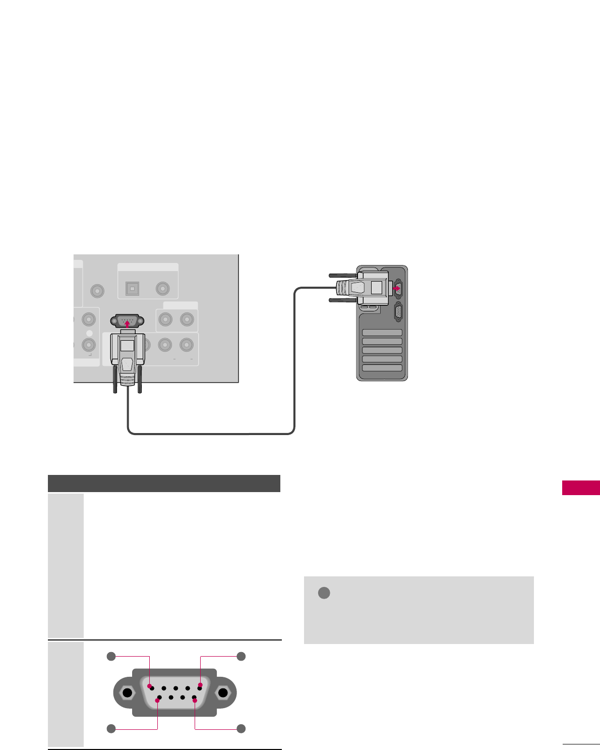
APPENDIX
107
EXTERNAL CONTROL THROUGH RS-232C
RS-232C Setup
The RS-232C port allows you connect the RS-232C input jack to an external control device (such as a computer
or an A/V control system) to control the TV’s functions externally.
■Note: RS-232C on this unit is intended to be used with third party RS-232C control hardware and software.
The instructions below are provided to help with programming software or to test functionality using telenet
software.
O
VI)
REMOTE
CONTROL IN
R
AUDIO
OPTICAL COAXIAL
DIGITAL AUDIO OUT
AV IN 1
VIDEO L R
(MONO)
AUDIO
S-VIDEO
AUDIO OUT
RS-232C IN
(CONTROL & SERVICE)
Type of Connector; D-Sub 9-Pin Male
No. Pin Name
1 No connection
2 RXD (Receive data)
3 TXD (Transmit data)
4 DTR (DTE side ready)
5 GND
6 DSR (DCE side ready)
7 RTS (Ready to send)
8 CTS (Clear to send)
9 No Connection
1
6
5
9
PC
Communication Parameters
■Baud rate : 9600 bps (UART)
■Data length : 8 bits
■Parity : None
■Stop bit : 1 bit
■Communication code : ASCII code
■Use a crossed (reverse) cable.
NOTE
!
GGThis product has command echo back in the
RS-232C Command.
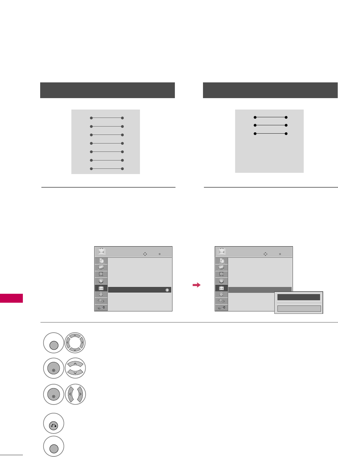
APPENDIX
108
RS-232C Configurations
APPENDIX
Use this function to specify a TV ID number.
Refer to ‘Real Data Mapping1’. GGpp..111111.
Either cable below can be used.
Set ID
PC TV
RXD 2 3 TXD
TXD 3 2 RXD
GND 5 5 GND
DTR 4 6 DSR
DSR 6 4 DTR
RTS 7 8 CTS
CTS 8 7 RTS
D-Sub 9 D-Sub 9
PC TV
RXD 2 3 TXD
TXD 3 2 RXD
GND 5 5 GND
DTR 4 6 DTR
DSR 6 4 DSR
RTS 7 7 RTS
CTS 8 8 CTS
D-Sub 9 D-Sub 9
7-Wire Configuration
(Serial female-female NULL modem cable)3-Wire Configurations
(Not standard)
Select OOPPTTIIOONN.
Select SSeett IIDD.
Choose the desired TV ID number.
The adjustment range of Set ID is 1~99.
1
MENU
3
2
ENTER
ENTER
4
RETURN
Return to the previous menu.
MENU
Return to TV viewing.
Enter
Move
OPTION
Language : English
Input Label
SIMPLINK : On
Key Lock : Off
Caption : Off
Set ID : 1
Power Indicator
Initial Setting : Home
Enter
Move
OPTION
Language : English
Input Label
SIMPLINK : On
Key Lock : Off
Caption : Off
Set ID : 1
Power Indicator
Initial Setting : Home
FF 1GG
Close
APPENDIX
109
Command Reference List
CCOOMMMMAANNDD11CCOOMMMMAANNDD22
19. Channel Tuning
DATA
(Hexadecimal)
CCOOMMMMAANNDD11CCOOMMMMAANNDD22
DATA
(Hexadecimal)
CCOOMMMMAANNDD11CCOOMMMMAANNDD22
DATA00
(Hexadecimal)
DATA01
(Hexadecimal)
DATA02
(Hexadecimal)
DATA03
(Hexadecimal)
DATA04
(Hexadecimal)
DATA05
(Hexadecimal)
physical major major low minor high minor low attribute
program high program low
ma
01. Power k a 00 ~01
02. Input Select x b (GGp.110)
03. Aspect Ratio k c (GGp.110)
04. Screen Mute k d 00 ~01
05. Volume Mute k e 00 ~01
06. Volume Control k f 00 ~64
07. Contrast k g 00 ~64
08. Brightness k h 00 ~64
09. Color k i 00 ~64
10. Tint k j 00 ~64
11. Sharpness k k 00 ~64
12. OSD Select k l 00 ~01
13. Remote Control
Lock Mode
Transmission / Receiving Protocol
TTrraannssmmiissssiioonn
[Command 1] : First command to control the set.(j, k, m or x)
[Command 2] : Second command to control the set.
[Set ID] : You can adjust the set ID to choose desired TV ID
number in Setup menu. Adjustment range is 1~99.
When selecting Set ID ‘0’, every connected the TV is
controlled. Set ID is indicated as decimal (1~ 99)on
menu and as Hexa decimal (0x0~ 0x63)on transmission
/receiving protocol.
[DATA] : To transmit the command data.
Transmit the ‘FF’ data to read status of command.
[Cr] : Carriage Return
ASCII code ‘0x0D’
[ ] : ASCII code ‘space (0x20)’
* In this model, TV will not send the status during the standby mode.
OOKK AAcckknnoowwlleeddggeemmeenntt
The TV transmits ACK (acknowledgement) based on this for-
mat when receiving normal data. At this time, if the data is
data read mode, it indicates present status data. If the data is
data write mode, it returns the data of the PC computer.
* In this model, TV will not send the status during the standby mode.
* Data Format
[Command 2] : Use as command.
[Set ID] : Use the small character, if set ID is 10, it will send the ‘0’, ‘a’.
[DATA] : Use the small character, if data is 0 x ab, it will send the ‘a’, ‘b’.
[OK] : Use the large character.
EErrrroorr AAcckknnoowwlleeddggeemmeenntt
The TV transmits ACK (acknowledgement) based on this for-
mat when receiving abnormal data from non-viable functions
or communication errors.
Data1: Illegal Code
Data2: Not supported function
Data3: Wait more time
* In this model, TV will not send the status during the standby mode.
* Data Format
[Command 2] : Use as command.
[Set ID] : Use the small character, if set ID is 10, it will send the ‘0’, ‘a’.
[DATA] : Use the small character, if data is 0 x ab, it will send the ‘a’, ‘b’.
[NG] : Use the large character
[[CCoommmmaanndd11]][[CCoommmmaanndd22]][[ ]][[SSeett IIDD]][[ ]][[DDaattaa]][[CCrr]]
[[CCoommmmaanndd22]][[ ]][[SSeett IIDD]][[ ]][[OOKK]][[DDaattaa]][[xx]]
[[CCoommmmaanndd22]][[ ]][[SSeett IIDD]][[ ]][[NNGG]][[DDaattaa]][[xx]]
14. Treble k r 00 ~64
15. Bass k s 00 ~64
16. Balance k t 00 ~64
17.
Color Temperature
k u 00 ~02
18. Auto Configuration j u (GGp.112)
20. Channel Add/Del m b 00 ~01
21 . Key m c ( GGp.113)
22. Backlight m g 00 ~64
00 ~01
k m

APPENDIX
110
APPENDIX
0011..PPoowweerr ((CCoommmmaanndd:: kk aa))
To control Power On/Off of the TV.
Transmission [k][a][ ][Set ID][ ][Data][Cr]
Data 00: Power Off Data 01: Power On
Acknowledgement [a][ ][Set ID][ ][OK/NG][Data][x]
* In a like manner, if other functions transmit ‘FF’ data
based on this format, Acknowledgement data feedback
presents status about each function.
* Note: In this model, TV will send the Acknowledge
after power on processing completion.
There might be a time delay between command and
acknowledge.
0022.. IInnppuutt SSeelleecctt ((CCoommmmaanndd:: xx bb))
To select input source for TV.
Transmission [x][b][ ][Set ID][ ][Data][Cr]
Data 00: DTV (Antenna) Data 01: DTV (Cable)
Data 10: Analog (Antenna) Data 11: Analog (Cable)
Data 20: AV1 Data 21: AV2
Data 40: Component 1 Data 41: Component 2
Data 60: RGB-PC Data 90: HDMI1
Data 91: HDMI2
Data 92: HDMI3 (Except 42/47/52LG50DC)
Acknowledgement [b][ ][Set ID][ ][OK/NG][Data][x]
0033.. AAssppeecctt RRaattiioo ((CCoommmmaanndd:: kk cc))
To adjust the screen format.
Transmission [k][c][ ][Set ID][ ][Data][Cr]
Data 01: 4:3 05: Zoom 2
02: 16:9 06: Set by program
04: Zoom 1 09: Just scan
Reserved
Acknowledgement [c][ ][Set ID][ ][OK/NG][Data][x]
0044..SSccrreeeenn MMuuttee ((CCoommmmaanndd:: kk dd))
To select screen mute on/off.
Transmission [k][d][ ][Set ID][ ][Data][Cr]
Data 00: Screen mute off (Picture on)
Data 01: Screen mute on (Picture off)
Acknowledgement [d][ ][Set ID][ ][OK/NG][Data][x]
0055.. VVoolluummee MMuuttee ((CCoommmmaanndd:: kk ee))
To control volume mute on/off.
You can also adjust mute using the MUTE button on
remote control.
Transmission [k][e][ ][Set ID][ ][Data][Cr]
Data 00: Volume mute on (Volume off)
Data 01: Volume mute off (Volume on)
Acknowledgement [e][ ][Set ID][ ][OK/NG][Data][x]
0066.. VVoolluummee CCoonnttrrooll ((CCoommmmaanndd:: kk ff))
To adjust volume.
You can also adjust volume with the volume buttons on
remote control.
Transmission [k][f][ ][Set ID][ ][Data][Cr]
Data Min: 00 ~Max: 64 (*transmit by Hexadecimal code)
*Refer to ‘Real data mapping’. See page 111.
Acknowledgement [f][ ][Set ID][ ][OK/NG][Data][x]
0077.. CCoonnttrraasstt ((CCoommmmaanndd:: kk gg))
To adjust screen contrast.
You can also adjust contrast in the PICTURE menu.
Transmission [k][g][ ][Set ID][ ][Data][Cr]
Data Min: 00 ~Max: 64 (*transmit by Hexadecimal code)
*Refer to ‘Real data mapping’. See page 111.
Acknowledgement [g][ ][Set ID][ ][OK/NG][Data][x]
0088.. BBrriigghhttnneessss ((CCoommmmaanndd:: kk hh))
To adjust screen brightness.
You can also adjust brightness in the PICTURE menu.
Transmission [k][h][ ][Set ID][ ][Data][Cr]
Data Min: 00 ~Max: 64 (*transmit by Hexadecimal code)
*Refer to ‘Real data mapping’. See page 111.
Acknowledgement [h][ ][Set ID][ ][OK/NG][Data][x]

APPENDIX
111
0099.. CCoolloorr ((CCoommmmaanndd:: kk ii))
To adjust screen color.
You can also adjust color in the PICTURE menu.
Transmission [k][i][ ][Set ID][ ][Data][Cr]
Data Min: 00 ~Max: 64 (*transmit by Hexadecimal code)
*Refer to ‘Real data mapping’ as shown below.
Acknowledgement [i][ ][Set ID][ ][OK/NG][Data][x]
1100.. TTiinntt ((CCoommmmaanndd:: kk jj))
To adjust screen tint.
You can also adjust tint in the PICTURE menu.
Transmission [k][j][ ][Set ID][ ][Data][Cr]
Data Red: 00 ~Green: 64 (*transmit by Hexadecimal code)
*Refer to ‘Real data mapping’ as shown below.
Acknowledgement [ j ][ ][Set ID][ ][OK/NG][Data][x]
1111.. SShhaarrppnneessss ((CCoommmmaanndd:: kk kk))
To adjust screen sharpness.
You can also adjust sharpness in the PICTURE menu.
Transmission [k][k][ ][Set ID][ ][Data][Cr]
Data Min: 00 ~Max: 64 (*transmit by Hexadecimal code)
*Refer to ‘Real data mapping’ as shown below.
Acknowledgement [k][ ][Set ID][ ][OK/NG][Data][x]
1122.. OOSSDD SSeelleecctt ((CCoommmmaanndd:: kk ll))
To select OSD (On Screen Display) on/off.
Transmission [k][l][ ][Set ID][ ][Data][Cr]
Data 00: OSD off Data 01: OSD on
Acknowledgement [l][ ][Set ID][ ][OK/NG][Data][x]
1133.. RReemmoottee CCoonnttrrooll LLoocckk MMooddee ((CCoommmmaanndd:: kk mm))
To lock the remote control and the front panel controls
on the set.
Transmission [k][m][ ][Set ID][ ][Data][Cr]
Data 00: Lock off Data 01: Lock on
Acknowledgement [m][ ][Set ID][ ][OK/NG][Data][x]
If you’re not using the remote control and front panel
controls on the TV, use this mode. When main power is
on/off, remote control lock is released.
1144.. TTrreebbllee ((CCoommmmaanndd:: kk rr))
To adjust treble.
You can also adjust treble in the AUDIO menu.
Transmission [k][r][ ][Set ID][ ][Data][Cr]
Data Min: 00 ~Max: 64 (*transmit by Hexadecimal code)
*Refer to ‘Real data mapping’ as shown.
Acknowledgement [r][ ][Set ID][ ][OK/NG][Data][x]
1155..BBaassss ((CCoommmmaanndd:: kk ss))
To adjust bass.
You can also adjust bass in the AUDIO menu.
Transmission [k][s][ ][Set ID][ ][Data][Cr]
Data Min: 00 ~Max: 64 (*transmit by Hexadecimal code)
*Refer to ‘Real data mapping’ as shown below.
Acknowledgement [s][ ][Set ID][ ][OK/NG][Data][x]
1166.. BBaallaannccee ((CCoommmmaanndd:: kk tt))
To adjust balance.
You can also adjust balance in the AUDIO menu.
Transmission [k][t][ ][Set ID][ ][Data][Cr]
Data Min: 00 ~Max: 64 (*transmit by Hexadecimal code)
*Refer to ‘Real data mapping’ as shown below.
Acknowledgement [t][ ][Set ID][ ][OK/NG][Data][x]
1177.. CCoolloorr TTeemmppeerraattuurree ((CCoommmmaanndd:: kk uu))
To adjust color temperature.
You can also adjust color temperature in the PICTURE menu.
Transmission [k][u][ ][Set ID][ ][Data][Cr]
Data 00: Medium 01: Cool 02: Warm
Acknowledgement [u][ ][Set ID][ ][OK/NG][Data][x]
*Real data mapping
0 : Step 0
A : Step 10 (SET ID 10)
F : Step 15 (SET ID 15)
10 : Step 16 (SET ID 16)
63 : Step 99 (SET ID 99)
64 : Step 100

APPENDIX
112
APPENDIX
1188.. AAuuttoo CCoonnffiigguurraattiioonn ((CCoommmmaanndd:: jj uu))
To adjust picture position and minimize image shaking
automatically. Auto configuration only works in RGB-PC
mode.
Transmission [ j ][u][ ][Set ID][ ][Data][Cr]
Data 1: To set
Acknowledgement [u][ ][Set ID][ ][OK/NG][Data][x]
1199.. CChhaannnneell TTuunniinngg ((CCoommmmaanndd:: mm aa))
To tune channel to following physical/major/minor number.
Transmission [m][a][ ][Set ID][ ][Data00][ ][Data01]
[ ][Data02][ ][Data03][ ][Data04][ ][Data05][Cr]
Digital channels have a Physical, Major, and Minor channel
number. The Physical number is the actual digital channel
number, the Major is the number that the channel should
be mapped to, and the Minor is the sub-channel. Since
the ATSC tuner automatically maps the channel to the
Major number, the Physical number is not required when
sending a command.
Data 00: Physical Channel Number
NTSC air: 02~45, NTSC cable: 01, 0E~7D
ATSC air: 01~45, ATSC cable: 01~87
Data 01 & 02: Major Channel Number
Data 01: High byte Data 02: Low byte
Two bytes are available for the Major and Minor, nor-
mally only the second byte is used.
Data 03 & 04: Minor Channel Number
Not needed for NTSC.

APPENDIX
113
Data05:
The table above lists the binary code which must be
converted to Hexadecimal before sending. For example:
The binary code to tune the sub source to an NTSC
cable channel is “1000 0001”, which translates to “81”
in Hex.
* 7th bit : For which source do you want to change the
channel.
* 6th bit: Use a two part or one part channel. Most cases
just use 0 since it’s ignored when using NTSC.
* 5th bit: Use 0 with NTSC since it can only use the phys-
ical channel number. Normally use 1 for ATSC since most
times it doesn’t matter what the physical number is.
* 4th bit: Set to 0.
* 3-0 bits: Choose signal type.
* Tune Command Examples:
1. Tune to the analog (NTSC) cable channel 35.
Data 00 = Physical of 35 = 23
Data 01 & 02 = No Major = 00 00
Data 03 & 04 = No Minor = 00 00
Data 05 = 0000 0001 in binary = 01
Total = ma 00 23 00 00 00 00 01
2. Tune to the digital (ATSC) local channel 30-3.
Data 00 = Don’t know Physical = 00
Data 01 & 02 = Major is 30 = 00 1E
Data 03 & 04 = Minor is 3 = 00 03
Data 05 = 0010 0010 in binary = 22
Total = ma 00 00 00 1E 00 03 22
Acknowledgement[a][ ][Set ID][ ][OK][Data00][Data01]
[Data02][Data03][Data04][x][a][ ][Set ID]
[ ][NG][Data00][x]
2200.. CChhaannnneell AAdddd//DDeell ((CCoommmmaanndd:: mm bb))
To add and delete the channels
Transmission [m][b][ ][Set ID][ ][Data][Cr]
Data 00: Channel Delete Data 01: Channel Add
Acknowledgement [b][ ][Set ID][ ][OK/NG][Data][x]
2211.. KKeeyy ((CCoommmmaanndd:: mm cc))
To send IR remote key code.
Transmission [m][c][ ][Set ID][ ][Data][Cr]
Data Key code: Refer to page 106.
Acknowledgement [c][ ][Set ID][ ][OK/NG][Data][x]
2222.. BBaacckklliigghhtt ((CCoommmmaanndd:: mm gg))
To adjust screen backlight.
Transmission [m][g][ ][Set ID][ ][Data][Cr]
Data Min:00 ~ Max:64 (*transmit by Hexadecimal code)
*Refer to ‘Real data mapping ’. See page 111.
Acknowledgement [g][ ][Set ID][ ][OK/NG][Data][x]
Step
NTSC Air
NTSC Cable
ATSC Air
ATSC Cable_std
ATSC Cable_hrc
ATSC Cable_irc
ATSC cable_auto
Reserved
...
Reserved
1
0
0
1
1
0
0
1
1
x
1
2
0
0
0
0
1
1
1
1
x
1
3
0
0
0
0
0
0
0
0
x
1
4
x
x
x
x
x
x
x
x
x
x
Reserved
5
0
1
Use
No Use
Using Physical
Channel
6
0
1
Two
One
Two/One
Part Channel
7
0
1
Main
Sub
Main/Sub
Picture 0
0
1
0
1
0
1
0
1
x
1
Regulatory Information cont.
FCC Compliance Statement
This equipment has been tested and found to comply
within the limits of a Class B digital device pursuant to Part
15 of the FCC Rules. These limits are designed to provide
reasonable protection against harmful interference in a
residential installation.
This equipment generates, uses, and can radiate radio
frequency energy and if not installed and used in
accordance with the instructions, may cause harmful
interference to radio communications. However, there is
no guarantee that interference will not occur in a particular
installation.
If this equipment does cause harmful interference to radio
or television reception (which can be determined by
turning the equipment on and off), the user is encouraged
to try to correct the interference by using one or more of
the following measures:
Reorient or relocate the receiving antenna.
Increase the separation between the equipment and
the receiver.
Connect the equipment into an outlet on a circuit
different from that to which the receiver is connected.
Consult the dealer or an experienced radio/TV
technician for help.
Caution: Changes or modifications not expressly approved
by the party responsible for compliance could void the
user's (or your) authority to operate the equipment. Only
peripherals (digital input/output devices, terminals, printers,
etc.) certified to comply with the Class B limits may be
attached to this monitor. Operation with non-certified
peripherals is likely to result in interference to radio and TV
reception. Only shielded signal cables may be used with
this System.
Canadian DOC Notice
This Class B digital apparatus meets all requirements of
the Canadian Interference-Causing Equipment
Regulations. Cet appareil numérique de la classe B
respecte toutes les exigences du Règlement sur le
matériel brouilleur du Canada.
CE Conformity Notice
(for Europe)
Products with the “CE” Marking comply with the EMC
Directive(89/336/EEC) and LOW VOLTAGE Directive
(73/23/EEC) issued by the Commission of the European
Community.
Compiance with these directives implies conformity to the
following European Norms :
• EN 55022 ; Radio Frequency Interference
• EN 55024 ; Electromagnetic Immunity
• EN 61000-3-2 ; Power Line Harmonics
• EN 61000-3-3 ; Voltage Fluctuations
• EN 60950-1 ; Product Safety
Low Radiation Compliance (MPR II)
This monitor meets one of the strictest guidelines available
today for low radiation emissions, offering the user extra
shielding and an antistatic screen coating. These
guidelines, set forth by a government agency in Sweden,
limit the amount of emission allowed in the Extremely Low
Frequency (ELF) and Very Low Frequency (VLF)
electromagnetic range.
01
NOTICE
The regulations are applied only to the products with the
ID LABEL indicating specific requirements.
NOTICE
The regulations are applied only to the products with the
ID LABEL indicating specific requirements.
NOTICE
The regulations are applied only to the products with the
ID LABEL indicating specific requirements.
TCO'99 (TCO'99 applied model only)
Congratulations!
You have just purchased a TCO’99 approved and labelled
product! Your choice has provided you with a product
developed for professional use. Your purchase has also
contributed to reducing the burden on the environment and
also to the further development of environmentally
adapted electronics products.

Regulatory Information cont.
02
Why do we have environmentally labelled computers?
In many countries, environmental labelling has become an
established method for encouraging the adaptation of
goods and services to the environment. With the growing
manufacture and usage of electronic equipment
throughout the world, there is a recognized concern for the
materials and substances used by electronic products
with regards to their eventual recycling and disposal. By
proper selection of these materials and substances, the
impact on the environment can be minimized.
There are also other characteristics of a computer, such as
energy consumption levels, that are important from the
viewpoints of both the work (internal) and natural (external)
environments. Electronic equipment in offices is often left
running continuously, resulting in unnecessary
consumption of large amounts of energy and additional
power generation. From the standpoint of carbon dioxide
emissions alone, it is vital to save energy.
What does labelling involve?
The product meets the requirements for the TCO’99
scheme which provides for international and environmental
labelling of personal computers and/or displays.
The labelling scheme was developed as a joint effort by the
TCO (The Swedish Confederation of Professional
Employees), Svenska Naturskyddsforeningen
(The Swedish Society for Nature Conservation) and
Statens Energimyndighet (The Swedish National
Energy Administration).
Approval requirements cover a wide range of issues:
ecology, ergonomics, emission of electrical and magnetical
fields, energy consumption and electrical safety.
Ecological criteria impose restrictions on the presence and
use of heavy metals, brominated and chlorinated flame
retardants, and other substances. The product must be
prepared for recycling and the manufacturing site(s) shall
be certified according to ISO14001 or EMAS registered.
Energy requirements include a demand that the system
unit and/or display, after a certain period of inactivity,
shall reduce its power consumption to a lower level in one
or more stages. The length of time to reactivate the system
unit shall be reasonable for the user.
Labelled products must meet strict environmental
demands, for example, in respect of the reduction of
electrical and magnetical fields as well as work load and
visual ergonomics.
Below you will find a brief summary of the ecological
requirements met by this product. The complete
ecological criteria document can be found at TCO
Development’s website http://www.tcodevelopment.com
or may be ordered from:
TCO Development
SE-114 94 STOCKHOLM, Sweden
Fax: +46 8 782 92 07
Email : development@tco.se
Information regarding TCO’99 approved and labelled
products may also be obtained at
http://www.tcodevelopment.com
Ecological requirements
Flame retardants
Flame retardants may be present in printed wiring board
laminates, cables, and housings. Their purpose is to
prevent, or at least to delay the spread of fire. Up to 30%
by weight of the plastic in a computer casing can consist of
flame retardant substances. Many flame retardants
contain bromine or chlorine, and these flame retardants
are chemically related to PCBs (polychlorinated
biphenyls). Both the flame retardants containing bromine
or chlorine and the PCBs are suspected of giving rise to
health effects, including reproductive damage in fish-
eating birds and mammals, due to the bio-accumulative*
processes when not disposed of in accordance with strict
standards for disposal.
TCO’99 requires that plastic components weighing more
than 25 grams shall not contain flame retardants with
organically bound bromine or chlorine. Flame retardants
are allowed in the printed wiring board laminates due to
the lack of commercially available alternatives.
Cadmium**
Cadmium is present in rechargeable batteries and in the
colour-generating layers of certain computer displays.
TCO’99 requires that batteries, the colour-generating
layers of display screens, and the electrical or electronics
components shall not contain any cadmium.
Mercury**
Mercury is sometimes found in batteries, relays and
switches. TCO’99 requires that batteries shall not contain
any mercury. It also demands that mercury is not present
in any of the electrical or electronics components
associated with the labelled unit. There is however one
Regulatory Information cont.
03
exception. Mercury is, for the time being, permitted in the
back light system of flat panel monitors as there today is
no commercially available alternative. TCO aims on
removing this exception when a mercury free alternative is
available.
Lead**
Lead can be found in picture tubes, display screens,
solders and capacitors. TCO’99 permits the use of lead
due to the lack of commercially available alternatives, but
in future requirements TCO Development aims at
restricting the use of lead.
_____________________________________________
* Bio-accumulative is defined as substances which
accumulate in living organisms.
**Lead, Cadmium and Mercury are heavy metals
which are bio-accumulative.
TCO’03
(TCO’03 applied model only)
Congratulations!
The display you have just purchased carries the TCO’03
Displays label.
This means that your display is designed,manufactured
and tested according to some of the strictest quality and
environmental requirements in the world. This makes for a
high performance product, designed with the user in focus
that also minimizes the impact on our natural environment.
Some of the features of the TCO’03 Display requirements:
Ergonomics
• Good visual ergonomics and image quality in order to
improve the working environment for the user and to
reduce sight and strain problems. Important
parameters are luminance, contrast, resolution,
reflectance, colour rendition and image stability.
Energy
• Energy-saving mode after a certain time – beneficial
both for the user and the environment
• Electrical safety
Emissions
• Electromagnetic fields
• Noise emissions
Ecology
• The product must be prepared for recycling and the
manufacturer must have a certified environmental
management system such as EMAS or ISO 14 001
• Restrictions on
chlorinated and brominated flame retardants and
polymers
heavy metals such as cadmium, mercury and lead.
The requirements included in this label have been
developed by TCO Development in co-operation with
scientists, experts, users as well as manufacturers all over
the world. Since the end of the 1980s TCO has been
involved in influencing the development of IT equipment in
a more user-friendly direction. Our labelling system started
with displays in 1992 and is now requested by users and
IT-manufacturers all over the world.
For more information, please visit
www.tcodevelopment.com
Information for Environmental Preservation
LGE. announced the 'LG Declaration for a Cleaner
Environment' in 1994, and this ideal has served as a
guiding managerial principle ever since. The Declaration is
a foundation that has allowed us to undertake
environmentally friendly activities in careful consideration
of economic, environmental, and social aspects.
We promote activities for environmental preservation, and
we specifically develop our products to embrace the
concept of environment-friendly.
We minimize the hazardous materials contained in our
products. For example, there is no cadmium to be found in
our monitors.
Information for recycling
This monitor may contain parts which could be hazardous
to the environment. It is important that this monitor be
recycled after use.
LGE. handles all waste monitors through an
environmentally acceptable recycling method. There are
several take-back and recycling systems currently in
English

Regulatory Information cont.
04
operation worldwide. Many parts will be reused and
recycled, while harmful substances and heavy metals are
treated by an environmentally friendly method.
If you want to find out more information about our
recycling program, please contact your local LG vendor or
a corporate representative of LG.
We set our vision and policies on a cleaner world by
selecting the issue of the global environment as a task for
corporate improvement. Please visit our website for more
information about our ‘green’ policies.
http://www.lge.com/about/environment/html/Recycling.jsp
Informationen zur Erhaltung der Umwelt
Im Jahr 1994 verkündete LGE die 'LG Declaration for a
Cleaner Environment' (LG Erklärung für eine sauberere
Umwelt). Seitdem dient dieses Ideal als führendes Prinzip
des Unternehmens. Diese Erklärung war die Basis für die
Durchführung von
umweltfreundlichen Aktivitäten, wobei wirtschaftliche,
umweltbezogene und soziale Aspekte in die
Überlegungen mit einbezogen wurden.
Wir fördern Aktivitäten zum Schutz der Umwelt und die
Entwicklung unserer Produkte ist darauf ausgerichtet,
unserem Konzept bezüglich Umweltfreundlichkeit gerecht
zu werden.
Wir sind darauf bedacht, den Anteil der in unseren
Produkten enthaltenen schädlichen Materialien zu
minimieren. So ist in unseren Monitoren beispielsweise
kein Kadmium zu finden.
Informationen zum Thema Recycling
Dieser Monitor enthält Teile, die umweltschädlich sein
können. Es ist unbedingt erforderlich, dass der Monitor
recycelt wird, nachdem er außer Dienst gestellt wurde.
Bei LGE. werden alle ausrangierten Monitore in einem
unter umweltbezogenen Aspekten geeigneten Verfahren
recycelt. Augenblicklich sind weltweit mehrere
Rücknahme- und Recyclingsysteme im Einsatz. Viele
Teile werden wieder verwendet und recycelt. Schädliche
Substanzen und Schwermetalle werden durch
umweltverträgliche Verfahren behandelt.
Falls Sie mehr über unser Recyclingprogramm erfahren
möchten, wenden Sie sich bitte an Ihren lokalen LG-
Händler oder einen Unternehmensvertreter von LG.
Wir richten unsere Firmenpolitik auf eine sauberere
Umwelt hin aus, indem wir umweltspezifische Aspekte als
wichtigen Punkt in die Weiterentwicklung unseres
Unternehmens einfließen lassen. Zusätzliche
Informationen über unsere ‘grüne’ Firmenpolitik erhalten
Sie auf unserer Website.
http://www.lge.com/about/environment/html/Recycling.jsp
Information sur la protection del’environnement
LGE. a publié sa 'Déclaration en faveur d’un
environnement plus propre' en 1994 et celle-ci est restée,
depuis lors, un principe directeur de notre entreprise.
Cette déclaration a servi de base à notre réflexion et nous
a permis de prendre en compte à la fois les aspects
économiques et sociaux de nos activités, tout en
respectant l’environnement.
Nous encourageons les activités en faveur de la
préservation de l’environnement et c’est dans cet esprit
que nous développons nos produits : nous réduisons au
minimum les matières dangereuses qui entrent dans leur
composition et l’on ne trouve pas de cadmium, par
exemple, dans nos moniteurs.
Information sur le recyclage
Ce moniteur peut contenir des composants qui présentent
un risque pour l’environnement. Il est donc important que
celui-ci soit recyclé après usage.
LGE. traite les moniteurs en fin de cycle conformément à
une méthode de recyclage respectueuse de
l’environnement. Nous reprenons nos produits et les
recyclons dans plusieurs sites répartis dans le monde
entier. De nombreux composants sont réutilisés et
recyclés, et les matières dangereuses, ainsi que les
métaux lourds, sont traités selon un procédé écologique.
Si vous souhaitez plus de renseignements sur notre
programme de recyclage, veuillez contacter votre
revendeur LG ou un l’un de nos représentants.
Nous voulons agir pour un monde plus propre et croyons
au rôle de notre entreprise dans l’amélioration de
l’environnement. Pour plus de renseignements sur notre
politique “verte”, rendez visite à notre site :
http://www.lge.com/about/environment/html/Recycling.jsp
Deutsch
Français
05
Regulatory Information cont.
Informazioni per la tutela dell’ambiente
La LGE. ha annunciato nel 1994 la cosiddetta 'LG
Declaration for a Cleaner Environment' (Dichiarazione di
LG a favore di un ambiente più pulito), un ideale che da
allora funge da principio ispiratore della gestione
aziendale. La dichiarazione rappresenta il fondamento che
consente di intraprendere attività a favore dell'ambiente
tenendo conto degli aspetti economici, ambientali e
sociali.Noi della LG, promuoviamo attività a favore della
tutela dell'ambiente sviluppando appositamente i nostri
prodotti per cogliere il concetto del rispetto dell’ambiente
riducendo i materiali dannosi presenti nei nostri prodotti.
Ad esempio nei nostri monitor non è presente il cadmio.
Informazioni per il riciclaggio
Il monitor può presentare componenti che potrebbero
risultare eventualmente dannosi per l'ambiente. È
importante che il monitor sia riciclato al termine del suo
utilizzo.
La LGE. gestisce tutti i monitor di rifiuto con un metodo di
riciclaggio soddisfacente dal punto di vista ambientale. In
tutto il mondo sono attualmente in funzione numerosi
sistemi di riciclaggio e recupero. I diversi componenti sono
riutilizzati e riciclati, mentre le sostanze dannose e i metalli
pesanti vengono trattati con un metodo rispettoso
dell’ambiente.
Se si desiderano maggiori informazioni in merito al
programma di riciclaggio, è consigliabile rivolgersi al
proprio rivenditore LG o ad un rappresentante aziendale
della LG.
Noi della LG impostiamo la nostra visione e le nostre
politiche a favore di un mondo più pulito ponendo la
questione dell'ambiente dal punto di vista globale come
una mansione rivolta al miglioramento della nostra
azienda. Vi invitiamo a visitare il nostro sito internet per
ulteriori informazioni sulla nostra politica “verde”.
http://www.lge.com/about/environment/html/Recycling.jsp
Información para la conservación
medioambiental
LGE. presentó la 'Declaración para un entorno más limpio
de LG' en 1994 y este ideal ha servido para guiar nuestros
principios empresariales desde entonces. La Declaración
es la base que nos ha permitido llevar a cabo tareas que
respetan el medio ambiente siempre teniendo en cuenta
aspectos sociales,
económicos y medioambientales.
Promocionamos actividades orientadas a la conservación
del medio ambiente y desarrollamos nuestros productos
específicamente para que se ajusten a la filosofía que
protege el entorno.
Reducimos al máximo el uso de materiales de riesgo en
nuestros productos. Un ejemplo de ello es la ausencia
total de cadmio en nuestros monitores.
Información para el reciclaje
Este monitor puede contener piezas que entrañen riesgos
medioambientales. Es importante reciclar este monitor
después de su utilización.
LGE. trata todos los monitores usados siguiendo un
método de reciclaje que no daña al entorno. Contamos
con diversos sistemas de recuperación y reciclaje que
funcionan a nivel mundial en la actualidad. Es posible
reciclar y reutilizar muchas de las piezas, mientras que las
sustancias dañinas y los metales pesados se tratan
siguiendo un método que no perjudique al medio
ambiente. Si desea obtener más información acerca del
programa de reciclaje, póngase en contacto con su
proveedor local de LG o con un representante empresarial
de nuestra marca.
Basamos nuestra visión y nuestras políticas en un mundo
más limpio y para ellos optamos por un entorno global
como tarea principal de nuestra evolución como empresa.
Visite nuestra página Web para obtener más información
sobre nuestras políticas ecológicas.
http://www.lge.com/about/environment/html/Recycling.jsp
Informações relacionadas à preservação
ambiental
A LGE. anunciou a 'LG Declaration for a Cleaner
Environment' (Declaração da LG para um ambiente mais
limpo) em 1994 e esse ideal tem servido desde então
como um princípio administrativo de orientação. A
Declaração é a base que nos tem permitido realizar
atividades favoráveis ao ambiente com consideração
atenta aos aspectos econômicos, ambientais e sociais.
Promovemos atividades de preservação ambiental e
desenvolvemos nossos produtos para englobar
Italiano
Espanõl
Português
06
Regulatory Information cont.
especificamente o conceito de favorável ao ambiente.
Reduzimos os materiais perigosos contidos em nossos
produtos. Por exemplo, não há cádmio em nossos
monitores.
Informações relacionadas à reciclagem
Este monitor pode conter peças que podem representar
riscos ao ambiente. É importante que ele seja reciclado
após o uso.
A LGE. cuida de todos os monitores descartados através
de um método de reciclagem agradável ao ambiente. Há
vários sistemas de devolução e reciclagem atualmente
em operação no mundo. Muitas peças serão reutilizadas
e recicladas e as substâncias nocivas e os metais
pesados passarão por tratamento através de um método
favorável ao ambiente.
Para obter mais informações sobre nosso programa de
reciclagem, entre em contato com seu fornecedor LG
local ou com um representante corporativo da LG.
Definimos nossa visão e nossas políticas relacionadas a
um mundo mais limpo selecionando a questão do
ambiente global como uma tarefa de aprimoramento
corporativo. Visite nosso site para obter mais informações
sobre nossas políticas de meio ambiente.
http://www.lge.com/about/environment/html/Recycling.jsp
Informatie met betrekking tot het behoud van
het milieu
LGE. publiceerde in 1994 de 'LG Declaration for a Cleaner
Environment' (de LG-verklaring met betrekking tot een
schoner milieu). Deze verklaring en het ideaal van een
schoner milieu fungeren sindsdien als een bestuurlijke
leidraad voor onze onderneming. Op basis van deze
verklaring ontplooien wij milieuvriendelijke activiteiten,
waarbij er zowel met sociale en economische aspecten,
als met milieuaspecten zorgvuldig rekening wordt
gehouden.
Wij ondersteunen activiteiten die zijn gericht op het
behoud van het milieu en wij houden bij het ontwikkelen
onze producten specifiek rekening met de
milieuvriendelijkheid van onze producten.
Wij minimaliseren het gebruik van schadelijke stoffen in
onze producten. Er wordt bijvoorbeeld geen cadmium
verwerkt in onze monitors.
Nederlands
Informatie met betrekking tot recycling
Deze monitor bevat materialen die schadelijk zouden
kunnen zijn voor het milieu. Het is belangrijk dat deze
monitor aan het einde van zijn levensduur wordt
gerecycled.
LGE. verwerkt alle afvalmonitors via een milieuvriendelijke
recyclingmethode. Hiervoor worden er momenteel
wereldwijd verscheidene inname- en recyclingsystemen
gehanteerd. Een groot aantal onderdelen wordt opnieuw
gebruikt en gerecycled, waarbij schadelijke stoffen en
zware metalen volgens een milieuvriendelijke methode
worden verwerkt.
Voor meer informatie over ons recyclingprogramma kunt u
contact opnemen met uw plaatselijke LG-
vertegenwoordiger of een LG-vestiging.
Onze visie en ons beleid met betrekking tot een schonere
wereld vloeien voort uit het feit dat wij het milieu hebben
aangemerkt als een onderwerp dat speciale aandacht
verdient binnen onze onderneming. Bezoek onze website
voor meer informatie over ons 'groene' beleid.
http://www.lge.com/about/environment/html/Recycling.jsp
»ÌÙÓχˆËˇ ÔÓ Óı‡Ì ÓÍÛʇ˛˘ÂÈ Ò‰˚
¬ 1994 „Ó‰Û ÍÓÔÓ‡ˆËˇ LGE ÓÔÛ·ÎËÍÓ‚‡Î‡
'ƒÂÍ·‡ˆË˛ LG ÔÓ Óı‡Ì ÓÍÛʇ˛˘ÂÈ Ò‰˚',
ÍÓÚÓ‡ˇ Ò ÚÂı ÔÓ ÒÎÛÊËÚ ÓÒÌÓ‚Ì˚Ï ÔË̈ËÔÓÏ
ÛÔ‡‚ÎÂÌˡ. Õ‡ ÓÒÌÓ‚Â ˝ÚÓÈ ‰ÂÍ·‡ˆËË Ï˚ ÒÏÓ„ÎË
Ô‰ÔËÌˇÚ¸ ‰ÂÈÒڂˡ, Ó·ÂÒÔ˜˂‡˛˘ËÂ
·ÂÁÓÔ‡ÒÌÓÒÚ¸ ÓÍÛʇ˛˘ÂÈ Ò‰˚, Û‰ÂΡˇ ÔË ˝ÚÓÏ
‰ÓÎÊÌÓ ‚ÌËχÌË ˝ÍÓÌÓÏ˘ÂÒÍËÏ, ˝ÍÓÎӄ˘ÂÒÍËÏ Ë
ÒӈˇθÌ˚Ï ‡ÒÔÂÍÚ‡Ï.
Ã˚ ÒÚËÏÛÎËÛÂÏ ‰ÂˇÚÂθÌÓÒÚ¸ ÔÓ Óı‡ÌÂ
ÓÍÛʇ˛˘ÂÈ Ò‰˚, Û‰ÂΡˇ ÓÒÓ·Ó ‚ÌËχÌËÂ
‡Á‡·ÓÚÍ ̇¯ÂÈ ÔÓ‰Û͈ËË ‚ ÒÓÓÚ‚ÂÚÒÚ‚ËË Ò
ÍÓ̈ÂÔˆËÂÈ ˝ÍÓÎӄ˘ÂÒÍÓÈ ·ÂÁÓÔ‡ÒÌÓÒÚË.
Ã˚ Ò‚Ó‰ËÏ Í ÏËÌËÏÛÏÛ ÒÓ‰ÂʇÌË ÓÔ‡ÒÌ˚ı
‚¢ÂÒÚ‚ ‚ ̇¯ÂÈ ÔÓ‰Û͈ËË. Õ‡ÔËÏÂ, ‚ ̇¯Ëı
ÏÓÌËÚÓ‡ı ‚˚ Ì ̇ȉÂÚ ͇‰Ïˡ.
»ÌÙÓχˆËˇ ÔÓ ÛÚËÎËÁ‡ˆËË ÓÚıÓ‰Ó‚
›ÚÓÚ ÏÓÌËÚÓ ÏÓÊÂÚ ÒÓ‰Âʇڸ ÍÓÏÔÓÌÂÌÚ˚,
ÍÓÚÓ˚ ÏÓ„ÛÚ Ì‡ÌÂÒÚË Û˘Â· ÓÍÛʇ˛˘ÂÈ Ò‰Â.
Russian
07
Regulatory Information cont.
EPA
(EPA applied model only)
ENERGY STAR
is a set of power-saving guidelines
issued by the U.S. Environmental Protection
Agency(EPA).
NOM MARK (Mexico only)
ÕÂÓ·ıÓ‰ËÏÓ ÛÚËÎËÁËÓ‚‡Ú¸ ÏÓÌËÚÓ ÔÓÒÎÂ
ËÒÔÓθÁÓ‚‡Ìˡ.
KÓÔÓ‡ˆËˇ LGE Ô‡·‡Ú˚‚‡ÂÚ ‚Ò ·‡ÍÓ‚‡ÌÌ˚Â
ÏÓÌËÚÓ˚ Ò ÔÓÏÓ˘¸˛ ˝ÍÓÎӄ˘ÂÒÍË ÔËÂÏÎÂÏÓ„Ó
ÏÂÚÓ‰‡ ÛÚËÎËÁ‡ˆËË ÓÚıÓ‰Ó‚. œÓ ‚ÒÂÏÛ ÏËÛ
‰ÂÈÒÚ‚Û˛Ú ÒËÒÚÂÏ˚ ÛÚËÎËÁ‡ˆËË ÓÚıÓ‰Ó‚ Ë ‚ÓÁ‚‡Ú‡
ËÒÔÓθÁÓ‚‡ÌÌÓÈ ÔÓ‰Û͈ËË. ÃÌÓ„Ë ÍÓÏÔÓÌÂÌÚ˚
·Û‰ÛÚ ‚ÚÓ˘ÌÓ ËÒÔÓθÁÓ‚‡Ì˚ Ë ÛÚËÎËÁËÓ‚‡Ì˚, ‚ ÚÓ
‚ÂÏˇ Í‡Í ‚‰Ì˚ ‚¢ÂÒÚ‚‡ Ë ÚˇÊÂÎ˚ ÏÂÚ‡ÎÎ˚
·Û‰ÛÚ Ó·‡·ÓÚ‡Ì˚ Ò ÔÓÏÓ˘¸˛ ˝ÍÓÎӄ˘ÂÒÍË
ÔËÂÏÎÂÏÓ„Ó ÏÂÚÓ‰‡.
«‡ ·ÓΠÔÓ‰Ó·ÌÓÈ ËÌÙÓχˆËÂÈ ÔÓ Ì‡¯ÂÈ
ÔÓ„‡ÏÏ ÛÚËÎËÁ‡ˆËË ÓÚıÓ‰Ó‚ Ó·‡˘‡ÈÚÂÒ¸ Í
ÏÂÒÚÌÓÏÛ ÔÓÒÚ‡‚˘ËÍÛ ËÎË Ô‰ÒÚ‡‚ËÚÂβ
ÍÓÔÓ‡ˆËË LG.
Ã˚ ÓËÂÌÚËÛÂÏÒˇ ̇ Ó·ÂÒÔ˜ÂÌË ˝ÍÓÎӄ˘ÂÒÍÓÈ
·ÂÁÓÔ‡ÒÌÓÒÚË, ÒÚ‡‚ˇ Ò· ˆÂθ˛ „ÎÓ·‡Î¸ÌÛ˛ Á‡˘ËÚÛ
ÓÍÛʇ˛˘ÂÈ Ò‰˚. ƒÓÔÓÎÌËÚÂθÌÛ˛ ËÌÙÓχˆË˛
Ó Ì‡¯ÂÈ ÔÓÎËÚËÍ ÔÓ Óı‡Ì ÓÍÛʇ˛˘ÂÈ Ò‰˚ ‚˚
ÏÓÊÂÚ ̇ÈÚË Ì‡ ̇¯ÂÏ Ò‡ÈÚÂ:
http://www.lge.com/about/environment/html/Recycling.jsp
As an ENERGY STAR Partner LGE U. S.
A.,Inc. has determined that this product
meets the ENERGY STAR guidelines for
energy efficiency.
08
Regulatory Information cont.
1.When this crossed-out wheeled bin symbol is attached
to a product it means the product is covered by the
European Directive 2002/96/EC.
2.All electrical and electronic products should be
disposed of separately from the municipal waste
stream via designated collection facilities appointed by
the government or the local authorities.
3.The correct disposal of your old appliance will help
prevent potential negative consequences for the
environment and human health.
4.For more detailed information about disposal of your
old appliance, please contact your city office, waste
disposal service or the shop where you purchased the
product.
Disposal of your old appliance
1.Quando su un prodotto è riportato il simbolo di
1.När den här symbolen med en överkryssad
soptunna på hjul sitter på en produkt innebär det
att den regleras av European Directive
2002/96/EC.
2.Alla elektriska och elektroniska produkter bör
kasseras via andra vägar än de som finns för
hushållsavfall, helst via för ändamålet avsedda
uppsamlingsanläggningar som myndigheterna
utser.
3.Om du kasserar din gamla apparat på rätt sätt
så bidrar du till att förhindra negativa
konsekvenser för miljön och människors hälsa.
4.Mer detaljerad information om kassering av din
gamla apparat kan får av kommunen,
renhållningsverket eller den butik där du köpte
produkten.
1.Als het symbool met de doorgekruiste verrijdbare
afvalbak op een product staat, betekent dit dat
het product valt onder de Europese Richtlijn
2002/96/EC.
2.Elektrische en elektronische producten mogen
niet worden meegegeven met het huishoudelijk
afval, maar moeten worden ingeleverd bij
speciale inzamelingspunten die door de lokale of
landelijke overheid zijn aangewezen.
3.De correcte verwijdering van uw oude toestel
helpt negatieve gevolgen voor het milieu en de
menselijke gezondheid voorkomen.
Smaltimento delle apparecchiature obsolete
Kassering av din gamla apparat
Uw oude toestel wegdoen
1.Ce symbole, représentant une poubelle sur
roulettes barrée d'une croix, signifie que le
produit est couvert par la directive européenne
2002/96/EC.
2.Les éléments électriques et électroniques
doivent être jetés séparément, dans les vide-
ordures prévus à cet effet par votre municipalité.
3.Une élimination conforme aux instructions aidera
à réduire les conséquences négatives et risques
éventuels pour l'environnement et la santé
humaine.
4.Pour plus d'information concernant l'élimination
de votre ancien appareil, veuillez contacter votre
mairie, le service des ordures ménagères ou
encore la magasin où vous avez acheté ce
produit.
Élimination de votre ancien appareil
un bidone della spazzatura barrato da una croce
significa che il prodotto è coperto dalla direttiva
europea 2002/96/EC.
2.Tutti i prodotti elettrici ed elettronici dovrebbero
essere smaltiti separatamente rispetto alla
raccolta differenziata municipale, mediante
impianti di raccolta specifici designati dal
governo o dalle autorità locali.
3.Il corretto smaltimento delle apparecchiature
obsolete contribuisce a prevenire possibili
conseguenze negative sulla salute umana e
sull'ambiente.
4.Per informazioni più dettagliate sullo smaltimento
delle apparecchiature obsolete, contattare il
comune, il servizio di smaltimento rifiuti o il
negozio in cui è stato acquistato il prodotto.
English
French
Italian
Swedish
Dutch
WEEE (for Europe )

Regulatory Information cont.
09
1.Wenn dieses Symbol eines durchgestrichenen
Abfalleimers auf einem Produkt angebracht ist,
unterliegt dieses Produkt der europäischen
Richtlinie 2002/96/EC.
2.Alle Elektro- und Elektronik-Altgeräte müssen
getrennt vom Hausmüll über dafür staatlich
vorgesehenen Stellen entsorgt werden.
3.Mit der ordnungsgemäßen Entsorgung des alten
Geräts vermeiden Sie Umweltschäden und eine
Gefährdung der persönlichen Gesundheit.
4.Weitere Informationen zur Entsorgung des alten
Geräts erhalten Sie bei der Stadtverwaltung,
beim Entsorgungsamt oder in dem Geschäft, wo
Sie das Produkt erworben haben.
1.ŸÙ·Ó ¤Ó· ÚÔ˚fiÓ ‰È·ı¤ÙÂÈ ÙÔ ‰‡Ì‚ÔÏÔ ÂÓfi˜
‰È·ÁÚ·Ì̤ÓÔ˘ οϷıÔ˘ ·ÔÚÚÈÌÌ¿ÙˆÓ, ÙfiÙ ÙÔ ÚÔ˚fiÓ
ηχÙÂÙ·È ·fi ÙËÓ E˘Úˆ·˚΋ O‰ËÁ›· 2002/96/EOK.
2.H ·fiÚÚÈ„Ë fiÏˆÓ ÙˆÓ ËÏÂÎÙÚÈÎÒÓ Î·È ËÏÂÎÙÚÔÓÈÎÒÓ
ÚÔ˚fiÓÙˆÓ Ú¤ÂÈ Ó· Á›ÓÂÙ·È ¯ˆÚÈÛÙ¿ ·fi Ù· ÁÂÓÈο
ÔÈÎȷο ·ÔÚÚ›ÌÌ·Ù· ̤ۈ ηıÔÚÈṲ̂ӈÓ
ÂÁηٷÛÙ¿ÛÂˆÓ Û˘ÏÏÔÁ‹˜ ·ÔÚÚÈÌÌ¿ÙˆÓ, ÔÈ Ôԛ˜
¤¯Ô˘Ó ‰ËÌÈÔ˘ÚÁËı› ›Ù ·fi ÙËÓ Î˘‚¤ÚÓËÛË ‹ ·fi ÙȘ
ÙÔÈΤ˜ ·Ú¯¤˜.
3.H ÛˆÛÙ‹ ·fiÚÚÈ„Ë Ù˘ ·ÏÈ¿˜ Û·˜ Û˘Û΢‹˜ ı·
‚ÔËı‹ÛÂÈ ÛÙËÓ ·ÔÙÚÔ‹ Èı·ÓÒÓ ·ÚÓËÙÈÎÒÓ Û˘ÓÂÈÒÓ
ˆ˜ ÚÔ˜ ÙÔ ÂÚÈ‚¿ÏÏÔÓ Î·È ÙËÓ ˘Á›· ÙÔ˘ ·ÓıÚÒÔ˘.
4.°È· ÈÔ ÏÂÙÔÌÂÚ›˜ ÏËÚÔÊÔڛ˜ Û¯ÂÙÈο Ì ÙËÓ
·fiÚÚÈ„Ë Ù˘ ·ÏÈ¿˜ Û·˜ Û˘Û΢‹˜, ÂÈÎÔÈÓˆÓ‹ÛÙ ÌÂ
ÙÔ ·ÚÌfi‰›Ô ÙÔÈÎfi ÁÚ·Ê›Ô, ˘ËÚÂÛ›· ‰È¿ıÂÛ˘ ÔÈÎÈ·ÎÒÓ
·ÔÚÚÈÌÌ¿ÙˆÓ ‹ ÙÔ Ì·Á·Í› ·fi ÙÔ ÔÔ›Ô ·ÁÔÚ¿Û·ÙÂ ÙÔ
ÚÔ˚fiÓ.
1.Tämä merkki tuotteessa tarkoittaa, että tuote
kuuluu sähkö- ja elektroniikkalaiteromusta
annetun EU-direktiivin 2002/96/EY
soveltamisalaan.
2.Kaikki elektroniset laitteet ovat ongelmajätettä,
joten ne on toimitettava paikalliseen
keräyspisteeseen.
3.Vanhan laitteen asianmukainen hävittäminen
ehkäisee mahdollisia ympäristöön ja
terveyteen kohdistuvia haittavaikutuksia.
4.Lisätietoa vanhan laitteen hävittämisestä saat
ottamalla yhteyden paikallisiin viranomaisiin,
kierrätyskeskukseen tai myymälään, josta ostit
laitteen.
1.Når der er et tegn med et kryds over en
skraldespand, betyder det, at produktet er
omfattet af EU-direktiv 2002/96/EC.
2.Alle elektriske og elektroniske produkter skal
smides ud et andet sted end gennem den
kommunale affaldsordning ved hjælp af specielle
indsamlingsfaciliteter, der er organiseret af staten
1.Si en un producto aparece el símbolo de un contenedor
de basura tachado, significa que éste se acoge a la
Directiva 2002/96/CE.
2.Todos los aparatos eléctricos o electrónicos se deben
desechar de forma distinta del servicio municipal de
recogida de basura, a través de puntos de recogida
designados por el gobierno o las autoridades locales.
3.La correcta recogida y tratamiento de los dispositivos
inservibles contribuye a evitar riesgos potenciales para el
medio ambiente y la salud pública.
4.Para obtener más información sobre cómo deshacerse de
sus aparatos eléctricos y electrónicos viejos, póngase en
contacto con su ayuntamiento, el servicio de recogida de
basuras o el establecimiento donde adquirió el producto.
Vanhojen laitteiden hävittäminen
Entsorgung von Altgeräten
Sådan smider du dit gamle apparat ud
∞fiÚÚÈ„Ë Ù˘ ·ÏÈ¿˜ Û·˜ Û˘Û΢‹˜
Cómo deshacerse de aparatos eléctricos y
electrónicos viejos
eller de lokale myndigheder.
3.Korrekt bortskaffelse af dit gamle apparat er med
til at forhindre mulige skadevirkninger på miljøet
og menneskelig sundhed.
4.Mere detaljerede oplysninger om bortskaffelse af
dit gamle apparat kan fås ved at kontakte dit
lokale kommunekontor, renovationsselskab eller
den butik, hvor du købte produktet.
Finnish
German
Danish
Greek
Spanish
4.Wilt u meer informatie over de verwijdering van
uw oude toestel? Neem dan contact op met uw
gemeente, de afvalophaaldienst of de winkel
waar u het product hebt gekocht.
Regulatory Information cont.
10
Portuguese
Slovak
Czech
Croatian
Hungarian
Polish
Regulatory Information cont.
11
Estonian
Latvian
Lithuanian