LG Electronics USA 50PC1DRAUA Plasma Display User Manual U512Aen
LG Electronics USA Plasma Display U512Aen
UserManual.wiki
>
LG Electronics USA
>
50PC1DRAUA User Manual
Users Manual
Navigation menu
Upload a User Manual
Namespaces
Wiki Guide
HTML
PDF
Info
Views
User Manual
Discussion / Help
Navigation
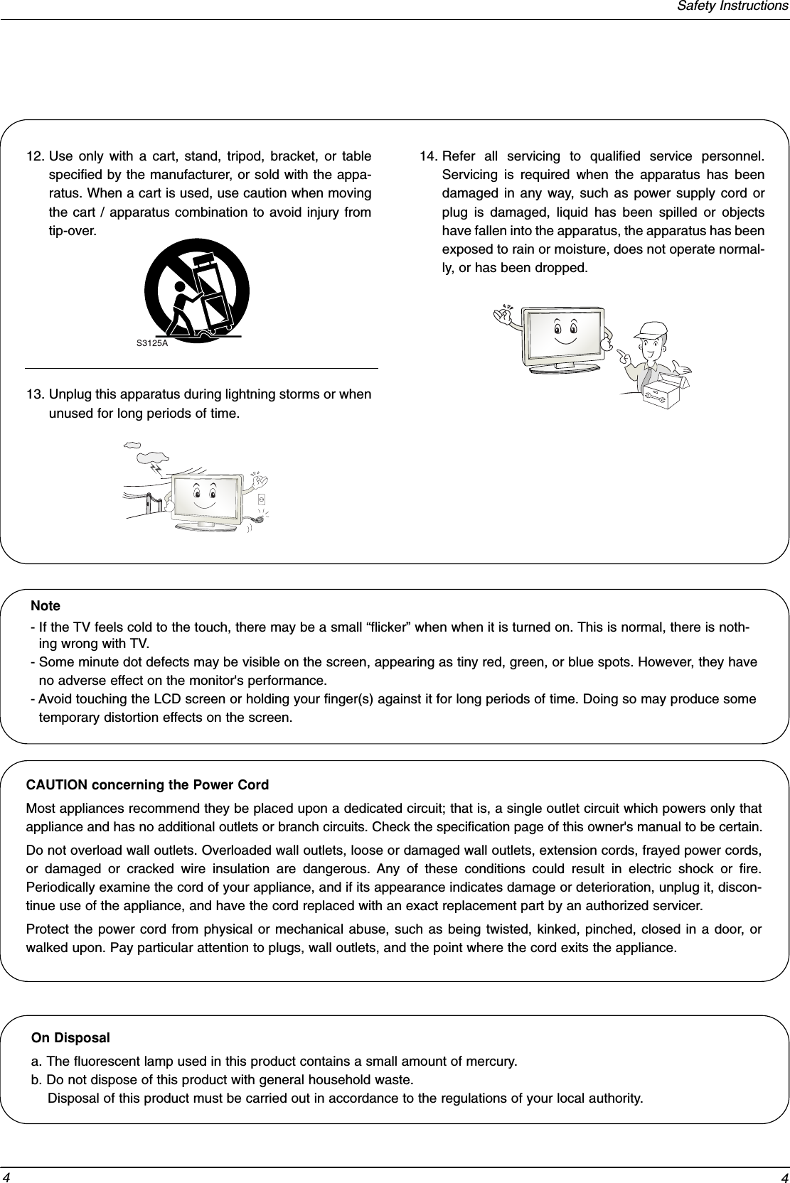
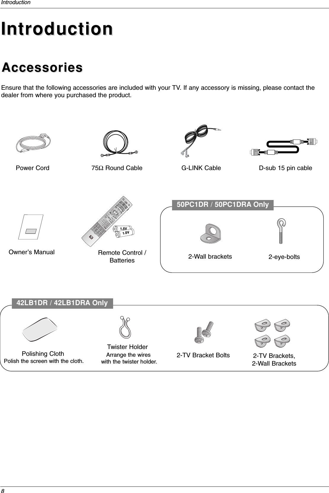
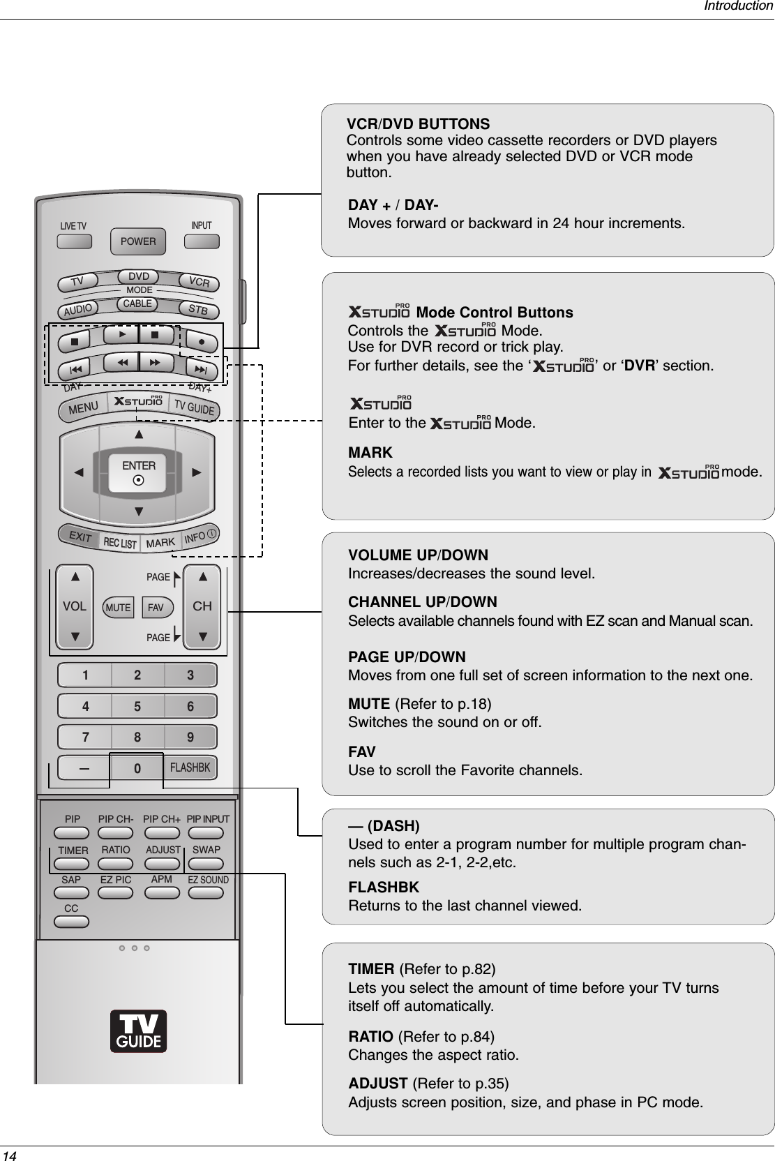
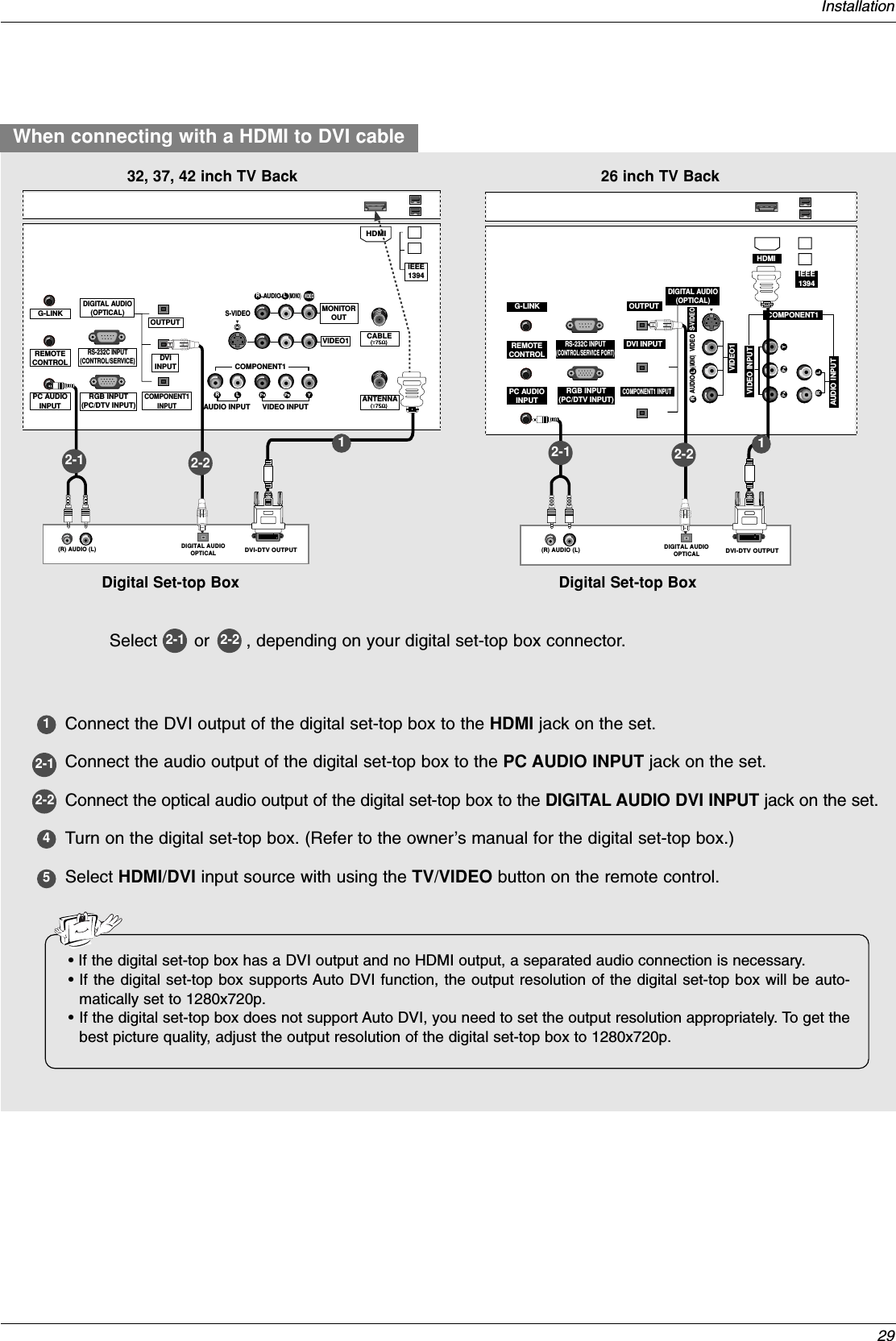
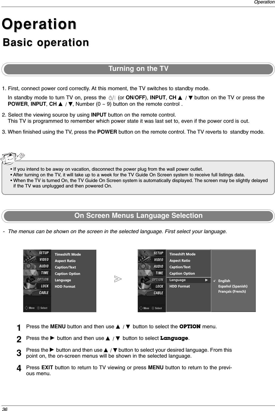
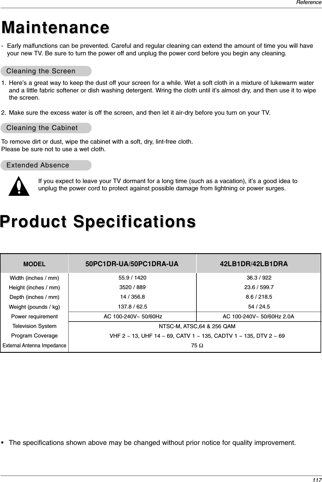
![105ReferenceSet IDSet ID- Use this function to specify a TV ID number. - Refer to ‘Real Data Mapping’. See page 104.• Baud rate : 9600 bps (UART)• Data length : 8 bits• Parity : None* Use a crossed (reverse) cable.• Stop bit : 1 bit• Communication code : ASCII codeCommunication ParametersCommunication Parameters1. Press the MENU button and then use DD /EEbutton to select theSETUP menu.2. Press the GGbutton and then use DD /EEbutton to select SET ID.3. Press the GGbutton and then use DD /EEbutton to adjust SET ID tochoose the desired TV ID number. The adjustment range of SET IDis 1 ~ 99.4. Press EXIT button to return to TV viewing or press MENU button toreturn to the previous menu.Transmission* [Command 1]: First command to control the set. (j or k)* [Command 2]: Second command to control the set.* [Set ID]: You can adjust the set ID to choose desired monitorID number in Setup menu. Adjustment range is 1~ 99. When selecting Set ID ‘0’, every connectedthe TV is controlled. Set ID is indicated as decimal(1~99) on menu and as Hexa decimal (0x0~0x63)on transmission/receiving protocol.* [DATA]: To transmit command data.Transmit ‘FF’data to read status of command.* [Cr]: Carriage ReturnASCII code ‘0x0D’* [ ]: ASCII code ‘space (0x20)’[Command1][Command2][ ][Set ID][ ][Data][Cr]TTransmission / Receiving Protocolransmission / Receiving ProtocolOK Acknowledgement* The Monitor transmits ACK (acknowledgement) based onthis format when receiving normal data. At this time, if thedata is data read mode, it indicates present status data. Ifthe data is data write mode, it returns the data of the PCcomputer.[Command2][ ][Set ID][ ][OK][Data][x]Error Acknowledgement* The Monitor transmits ACK (acknowledgement) based onthis format when receiving abnormal data from non-viablefunctions or communication errors.[Command2][ ][Set ID][ ][NG][Data][x]Data 1: Illegal Code2: Not supported function3: Wait more time01. Power k a 0 ~ 102. Input Select k b 0 ~ 803. Aspect Ratio k c * 04. Screen Mute k d 0 ~ 105. Volume Mute k e 0 ~ 206. Volume Control k f 0 ~ 6407. Contrast k g 0 ~ 6408. Brightness k h 0 ~ 6409. Color k i 0 ~ 6410. Tint k j 0 ~ 6411. Sharpness k k 0 ~ 6412. OSD Select k l 0 ~ 113. Remote Control Lock Mode k m 0 ~ 114. PIP/POP/Twin Picture k n 0,1,2,515. PIP Position k q 0 ~ 316. Treble k r 0 ~ 6417. Bass k s 0 ~ 6418. Balance k t 0 ~ 6419. Color Temperature k u 0 ~ 220. PIP Input Source k y 0 ~ 324. Input Select x b *25. PIP Input Select x y *COMMAND 1 COMMAND 2 DATA(Hexadecimal)21. Channel Tuning m a 01 ~ 87 01 ~ 87 00 ~ FE 00 ~ FE 00 ~ FE 00 ~ FE22. Channel Add/Del m b 00 ~ 0123. Key m c *COM-MAND 2COM-MAND 1DATA 0(Hexadecimal)DATA 1(Hexadecimal)DATA 2(Hexadecimal)DATA 3(Hexadecimal)DATA 4(Hexadecimal)DATA 5(Hexadecimal)Command Reference ListCommand Reference ListSETUPVIDEOAUDIOTIMEOPTIONLOCKCABLE PreviousMENUEZ ScanManual ScanChannel EditDTV SignalChannel LabelMain InputSub InputInput LabelSet ID G1](https://usermanual.wiki/LG-Electronics-USA/50PC1DRAUA/User-Guide-603659-Page-22.png)
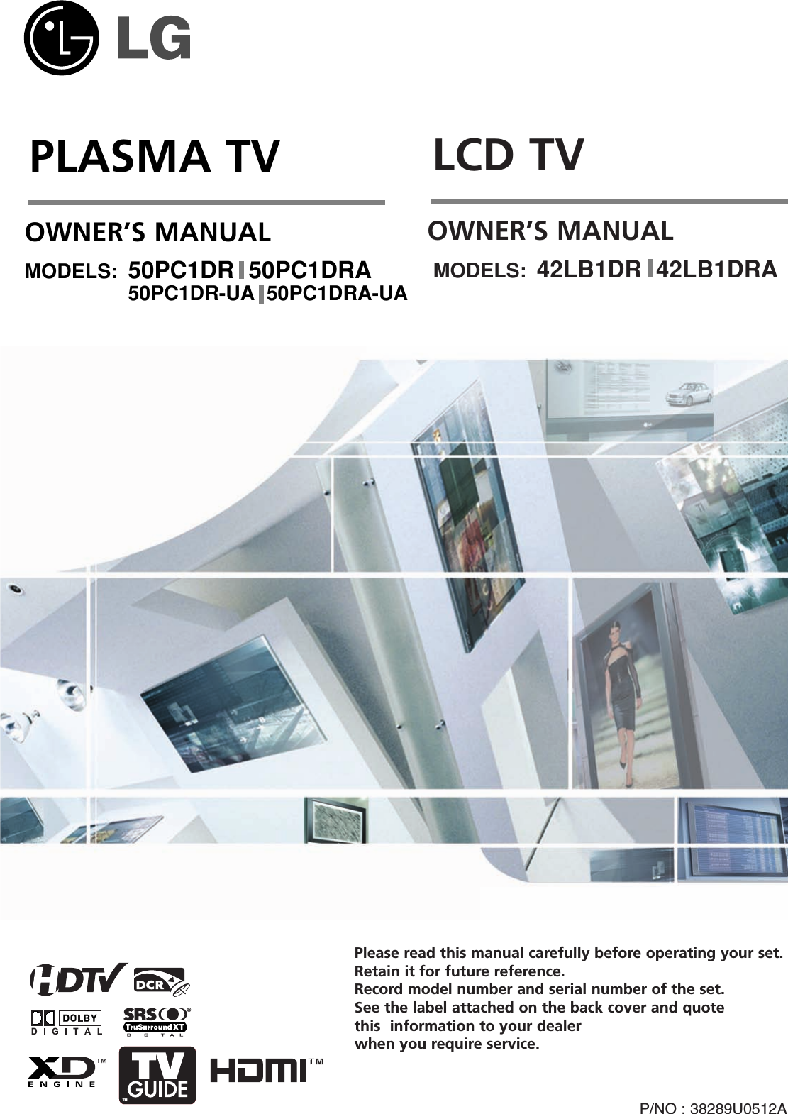
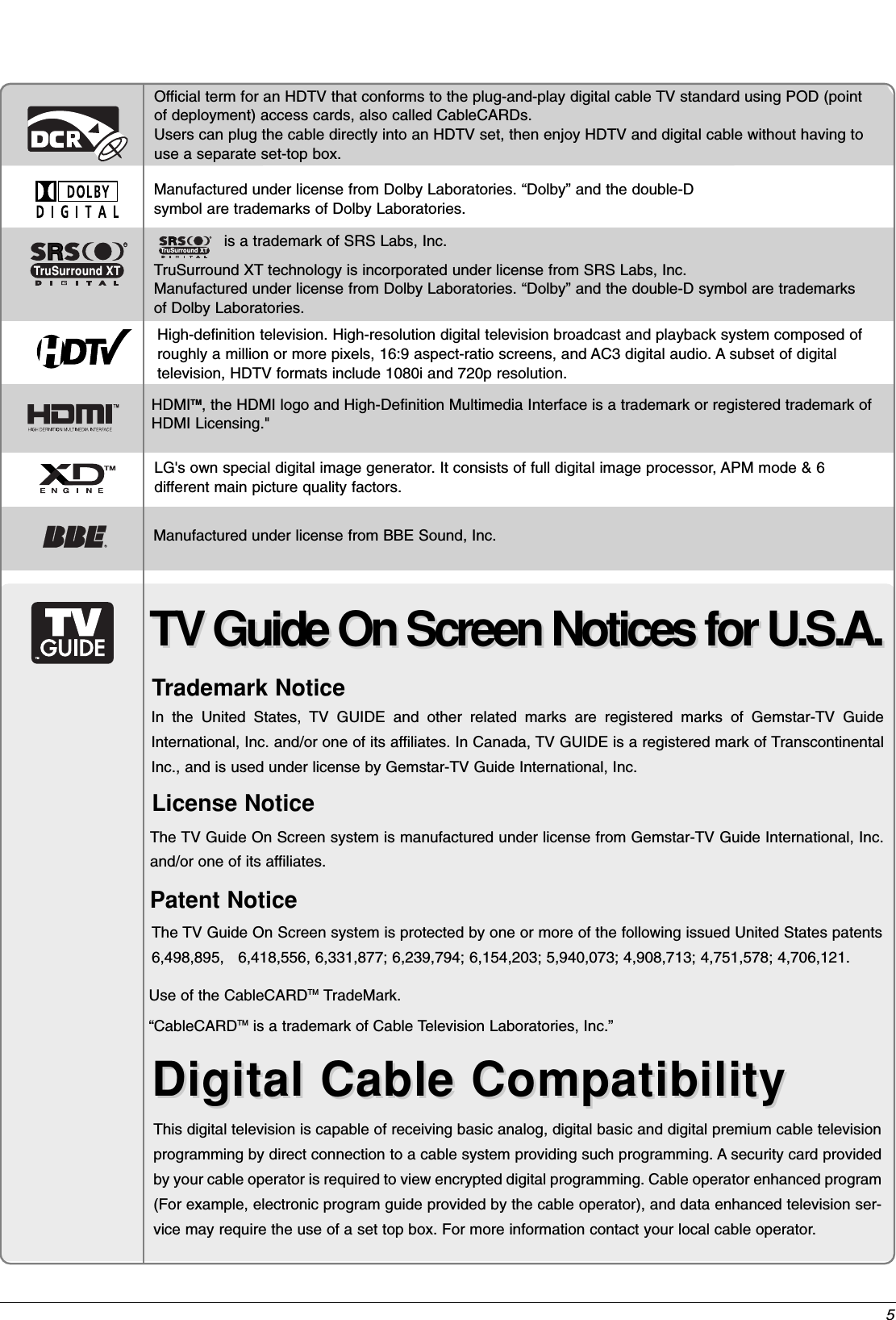
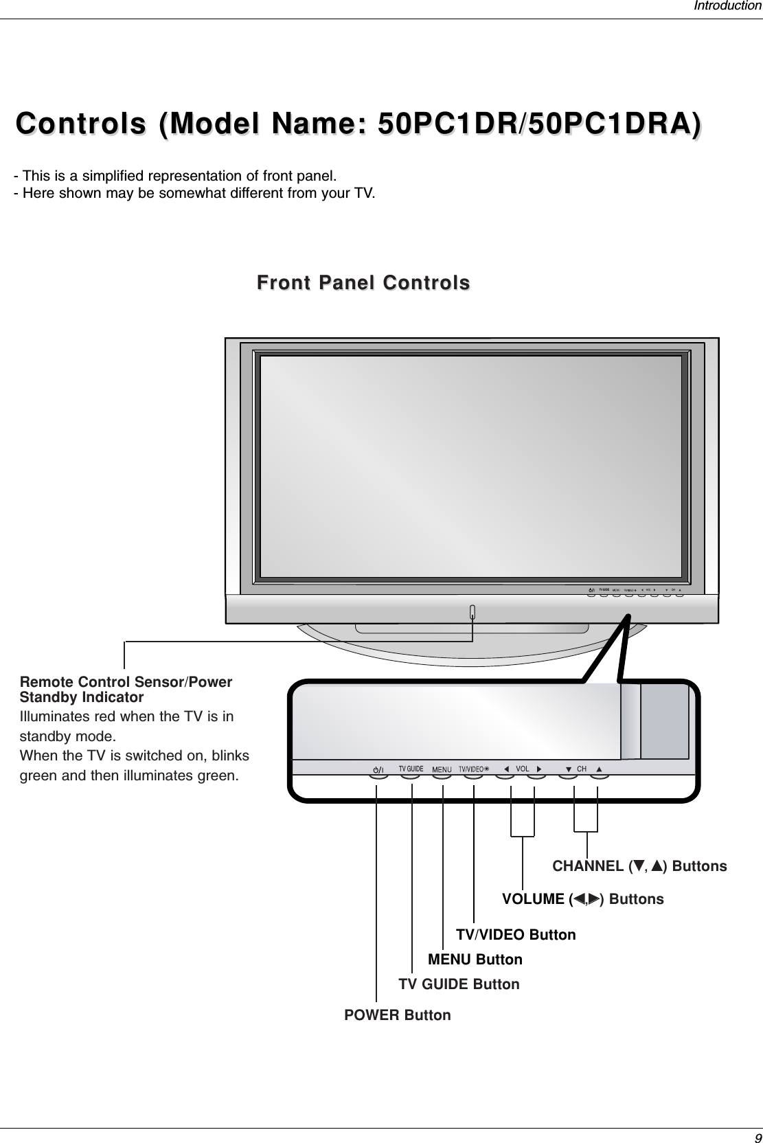
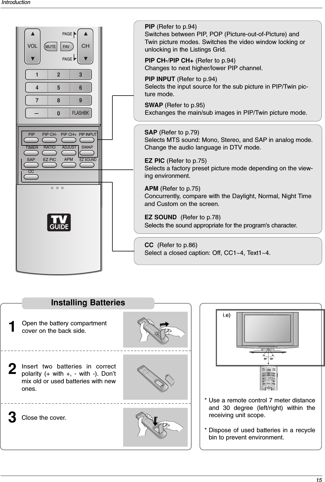
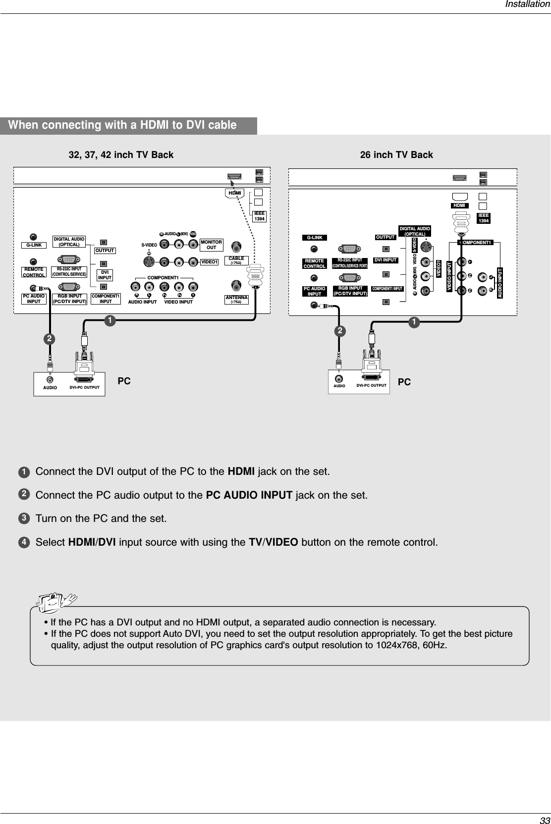
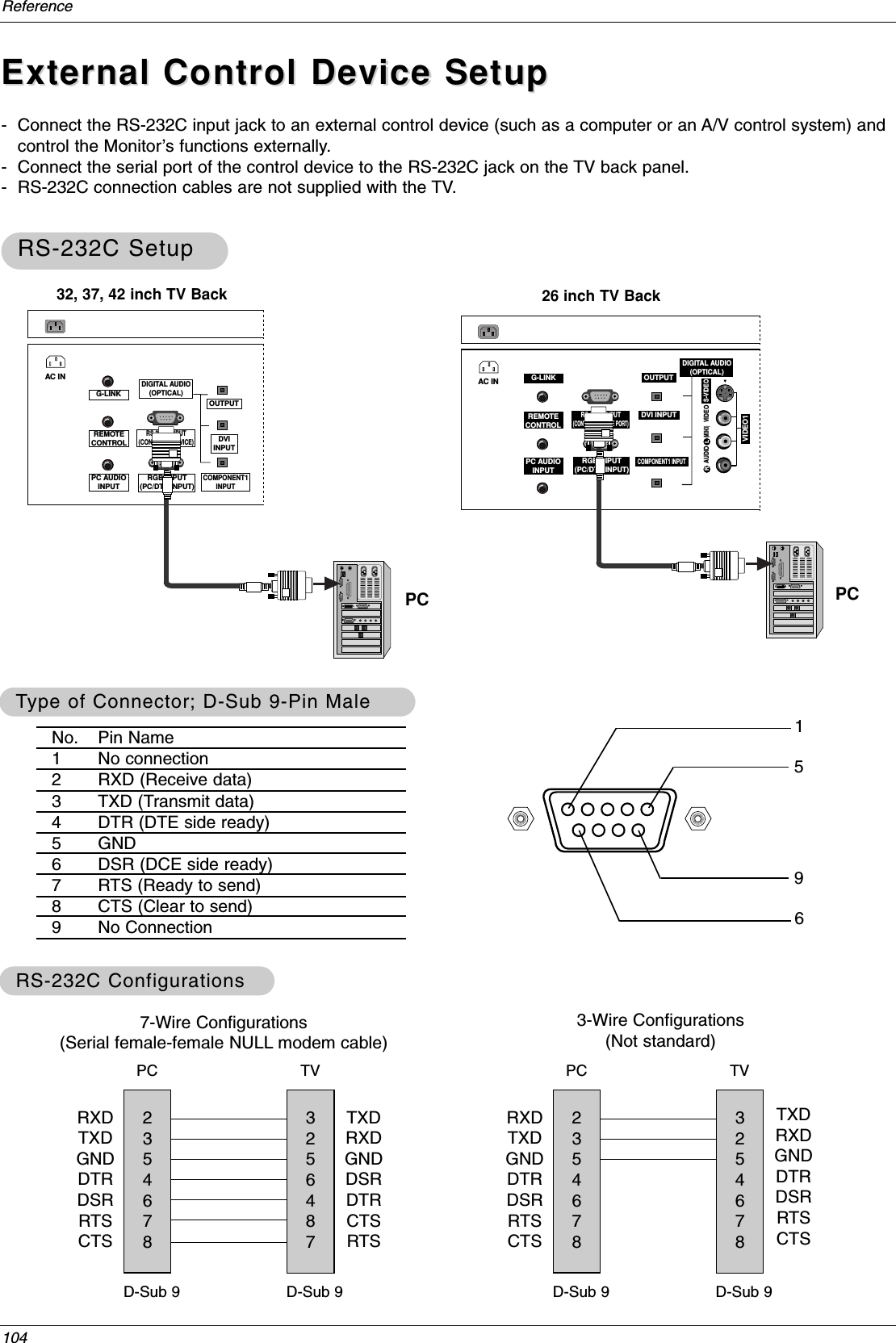
![106Reference02. Input Select (Command2:b) (Main Picture Input)GTo select input source for the TV.TransmissionData 0: DTV1: Analog2: Video 13: Video 24: Component 15: Component 26: RGB-DTV7: RGB-PC8: HDMI/DVIData 1: Normal screen (4:3)2: Wide screen (16:9)3: Horizon4: Zoom 15: Zoom 26: Auto (Set by program)10: Cinema Zoom (1)1F: Cinema Zoom (16)[k][b][ ][Set ID][ ][Data][Cr]Acknowledgement[b][ ][Set ID][ ][OK][Data][x]01. Power (Command2:a)GTo control Power On/Off of the TV.TransmissionData 0 : Power Off 1 : Power On[k][a][ ][Set ID][ ][Data][Cr]Acknowledgement[a][ ][Set ID][ ][OK][Data][x]* In a like manner, if other functions transmit ‘FF’databased on this format, Acknowledgement data feedbackpresents status about each function.* Real data mapping0 : Step 0A : Step 10 (SET ID 10)F : Step 15 (SET ID 15)10 : Step 16 (SET ID 16)64 : Step 10005. Volume Mute (Command2:e)GTo control volume mute on/off.You can also adjust mute using the MUTE button onremote control.TransmissionData 0 : Volume mute off (Volume on)1 : Volume mute on (Volume off)2 : Volume mute on, Caption on[k][e][ ][Set ID][ ][Data][Cr]Acknowledgement[e][ ][Set ID][ ][OK][Data][x]03. Aspect Ratio (Command2:c) (Main picture format)GTo adjust the screen format.You can also adjust the screen format using the RATIObutton on remote control or in the Option menu.Transmission[k][c][ ][Set ID][ ][Data][Cr]Acknowledgement[c][ ][Set ID][ ][OK][Data][x]04. Screen Mute (Command2:d)GTo select screen mute on/off.TransmissionData 0: Screen mute off (Picture on)1: Screen mute on (Picture off)[k][d][ ][Set ID][ ][Data][Cr]Acknowledgement[d][ ][Set ID][ ][OK][Data][x]06. Volume Control (Command2:f)GTo adjust volume.You can also adjust volume with the volume buttonson remote control.TransmissionData Min : 0 ~ Max : 64•Refer to ‘Real data mapping’as shown below.[k][f][ ][Set ID][ ][Data][Cr]Acknowledgement[f][ ][Set ID][ ][OK][Data][x]07. Contrast (Command2:g)GTo adjust screen contrast. You can also adjust contrast in the Video menu.TransmissionData Min : 0 ~ Max : 64•Refer to ‘Real data mapping’as shown below.[k][g][ ][Set ID][ ][Data][Cr]Acknowledgement[g][ ][Set ID][ ][OK][Data][x]08. Brightness (Command2:h)GTo adjust screen brightness.You can also adjust brightness in the Video menu.TransmissionData Min : 0 ~ Max : 64•Refer to ‘Real data mapping’as shown below.* Tint: R 50 ~ G 50[k][h][ ][Set ID][ ][Data][Cr]Acknowledgement[h][ ][Set ID][ ][OK][Data][x]](https://usermanual.wiki/LG-Electronics-USA/50PC1DRAUA/User-Guide-603659-Page-23.png)
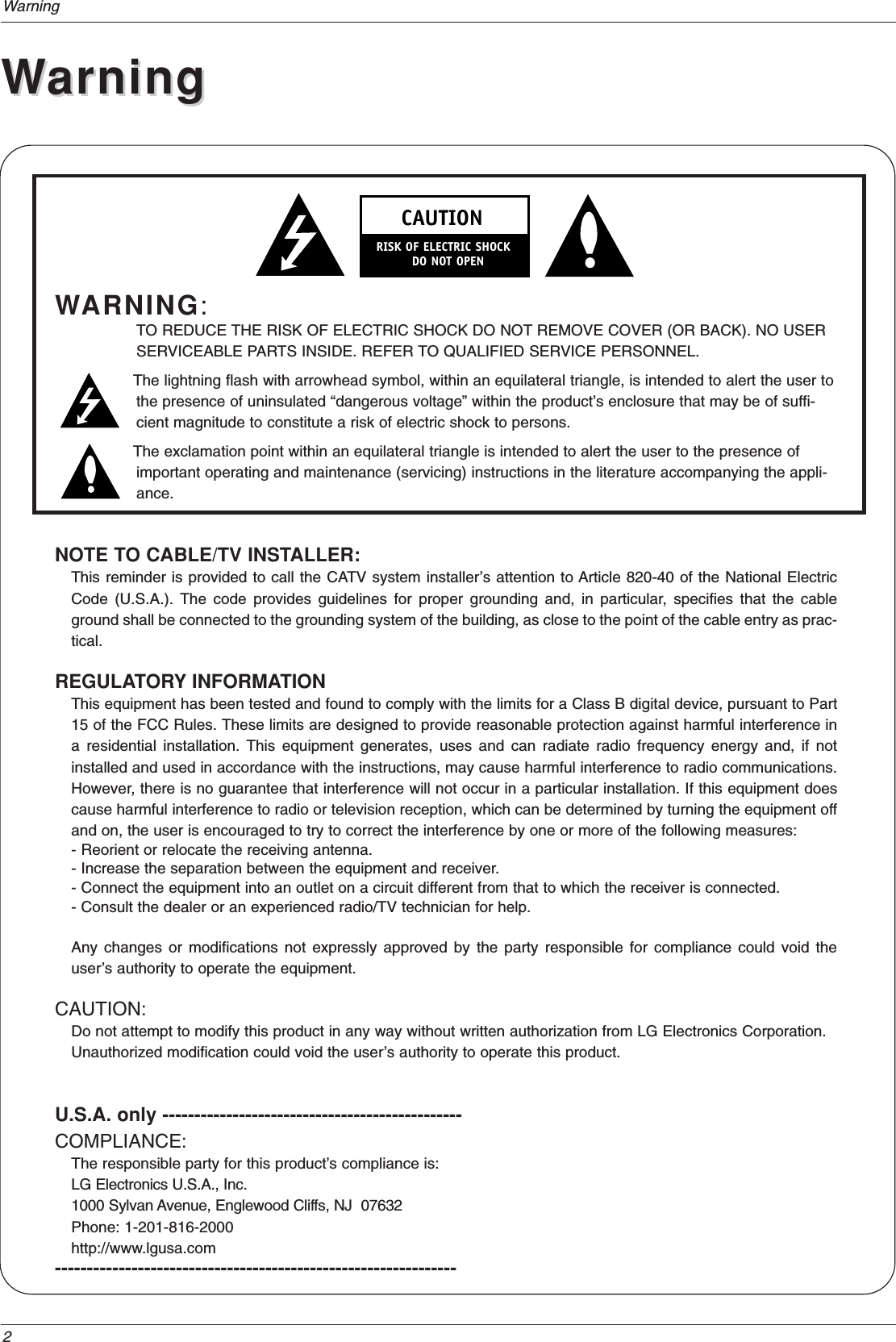
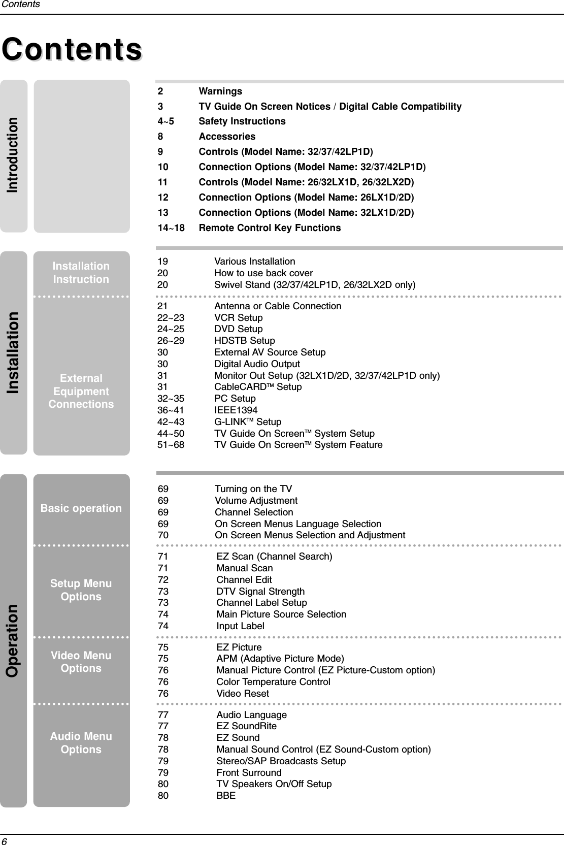
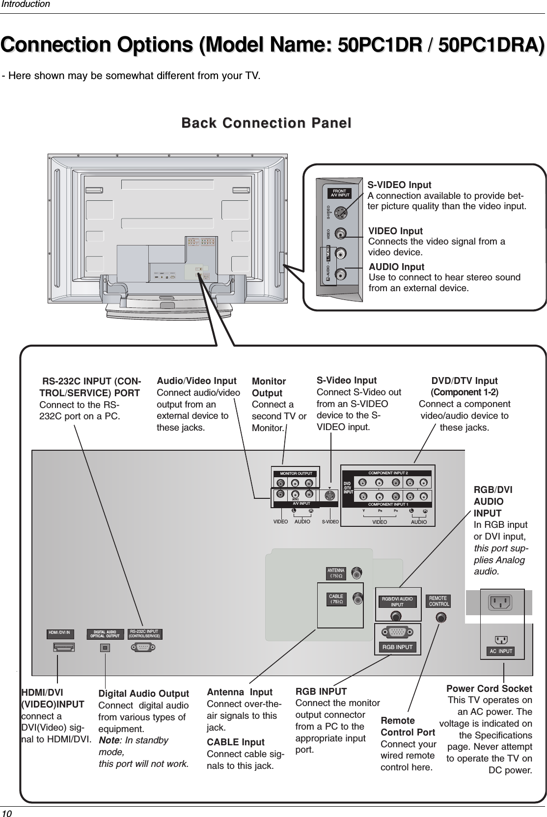
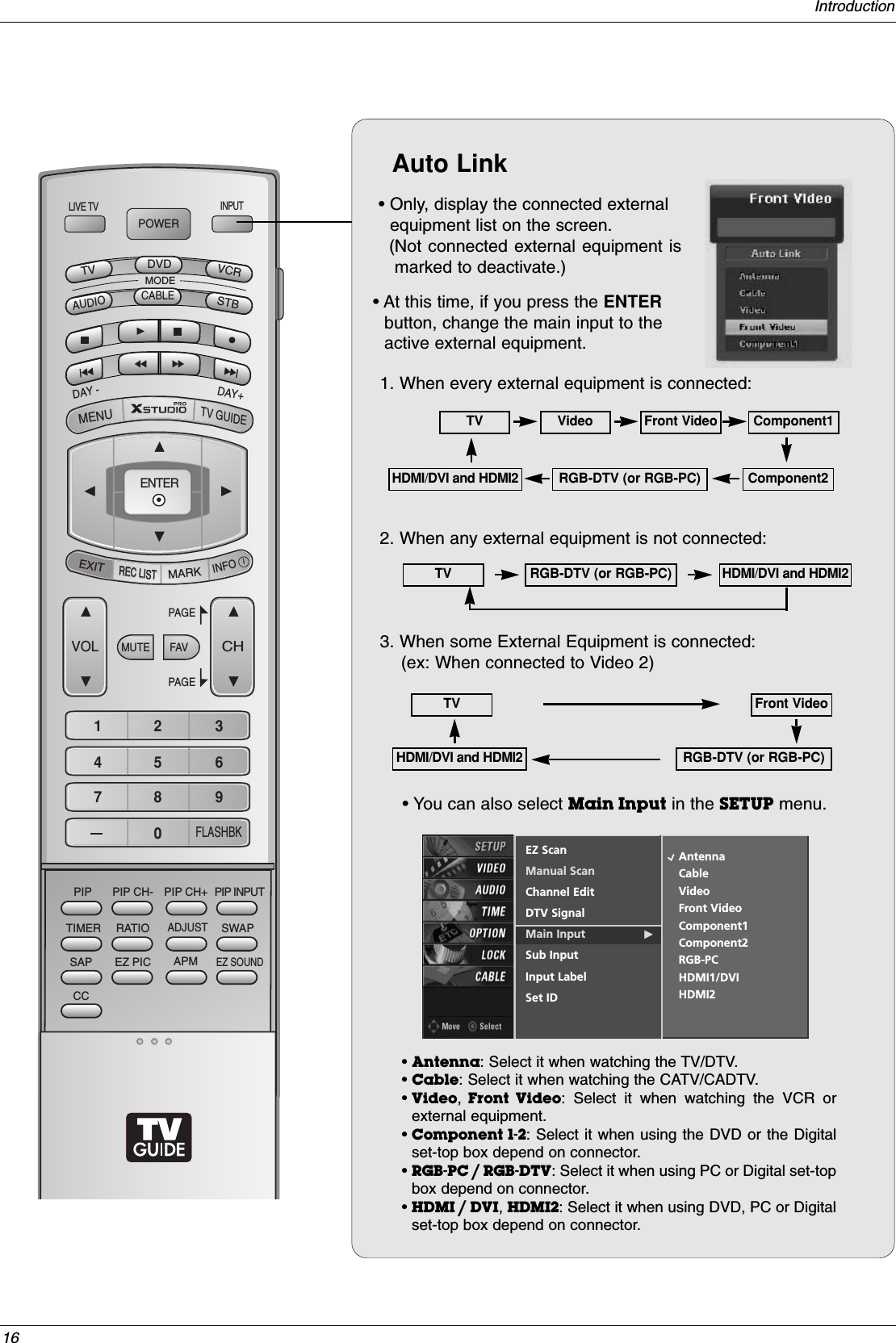
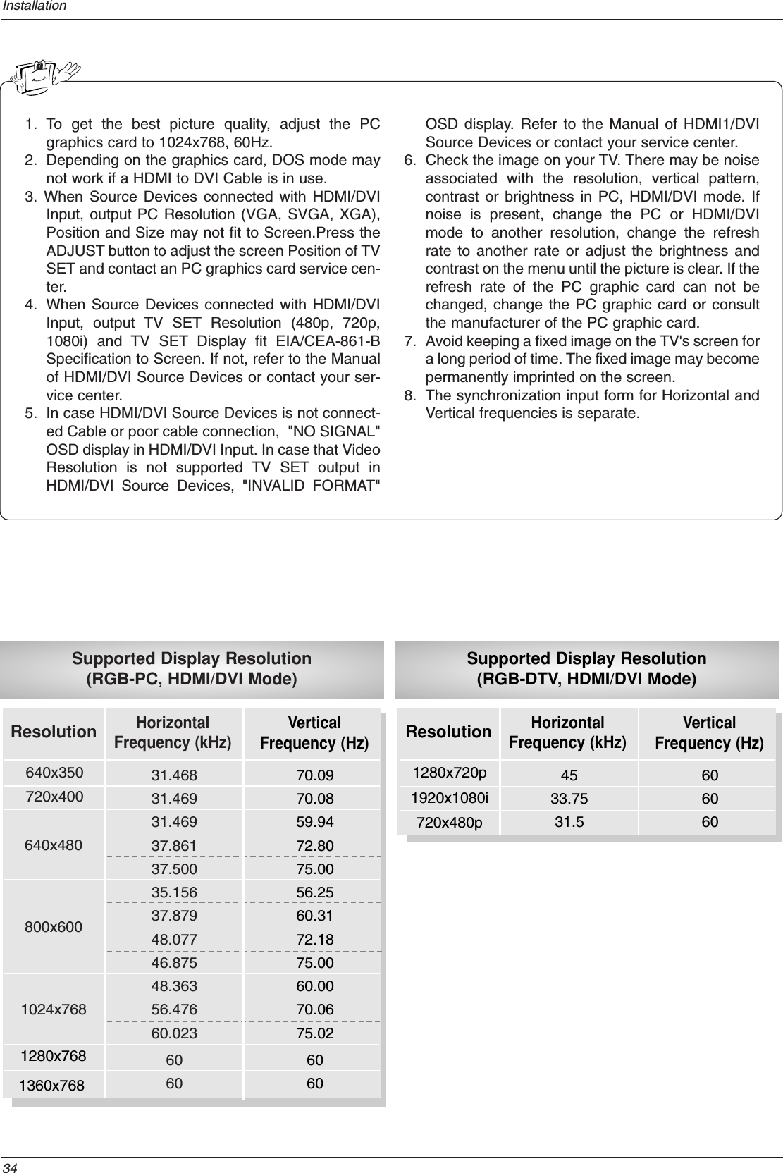
![107Reference09. Color (Command2:i)GTo adjust the screen color.You can also adjust color in the Video menu.TransmissionData Min : 0 ~ Max : 64•Refer to ‘Real data mapping’. See page 104.[k][i][ ][Set ID][ ][Data][Cr]Acknowledgement[i][ ][Set ID][ ][OK][Data][x]10. Tint (Command2:j)GTo adjust the screen tint.You can also adjust tint in the Video menu.TransmissionData Red : 0 ~ Green : 64•Refer to ‘Real data mapping’. See page 104.[k][j][ ][Set ID][ ][Data][Cr]Acknowledgement[j][ ][Set ID][ ][OK][Data][x]13. Remote Control Lock Mode (Command2:m)GTo lock the remote control and the front panel controls onthe set.Transmission[k][m][ ][Set ID][ ][Data][Cr]AcknowledgementData 0: Lock off 1: Lock on[m][ ][Set ID][ ][OK][Data][x]14. PIP/POP/Twin Picture (Command2:n)GTo control the PIP (Picture-in-Picture)/POP/Twin picture.You can also control the PIP/POP/Twin picture using thePIP button on the remote control.TransmissionData 0: PIP off1: PIP2: Twin Picture5: POP[k][n][ ][Set ID][ ][Data][Cr]Acknowledgement[n][ ][Set ID][ ][OK][Data][x]GTo adjust the screen sharpness.You can also adjust sharpness in the Video menu.Transmission11. Sharpness (Command2:k)Data Min: 0 ~ Max: 64•Refer to ‘Real data mapping’. See page 104.[k][k][ ][Set ID][ ][Data][Cr]Acknowledgement[k][ ][Set ID][ ][OK][Data][x]12. OSD Select (Command2:l)GTo select OSD (On Screen Display) on/off.Transmission[k][l][ ][Set ID][ ][Data][Cr]AcknowledgementData 0: OSD off 1: OSD on[l][ ][Set ID][ ][OK][Data][x]15. PIP Position (Command2:q)GTo select sub picture position for PIP.Transmission[k][q][ ][Set ID][ ][Data][Cr]AcknowledgementData 0: Right down on screen1: Left down on screen2: Left up on screen3: Right up on screen[q][ ][Set ID][ ][OK][Data][x]16. Treble (Command2:r)GTo adjust treble.You can also adjust treble in the Audio menu.TransmissionData Min: 0 ~ Max: 64•Refer to ‘Real data mapping’. See page 104.[k][r][ ][Set ID][ ][Data][Cr]Acknowledgement[r][ ][Set ID][ ][OK][Data][x]18. Balance (Command2:t)GTo adjust balance.You can also adjust balance in the Audio menu.TransmissionData Min: 0 ~ Max: 64•Refer to ‘Real data mapping’. See page 104.[k][t][ ][Set ID][ ][Data][Cr]Acknowledgement[t][ ][Set ID][ ][OK][Data][x]17. Bass (Command2:s)GTo adjust bass.You can also adjust bass in the Audio menu.TransmissionData Min: 0 ~ Max: 64•Refer to ‘Real data mapping’. See page 104.[k][s][ ][Set ID][ ][Data][Cr]Acknowledgement[s][ ][Set ID][ ][OK][Data][x]](https://usermanual.wiki/LG-Electronics-USA/50PC1DRAUA/User-Guide-603659-Page-24.png)
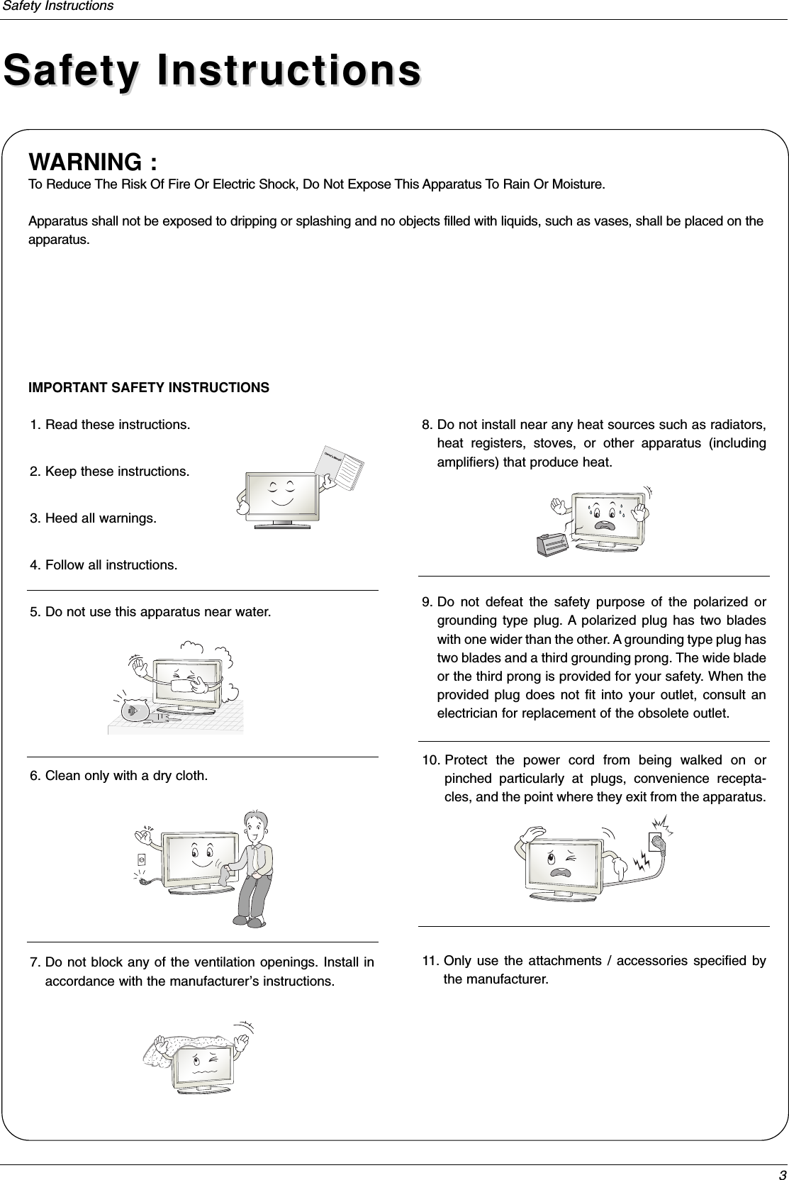
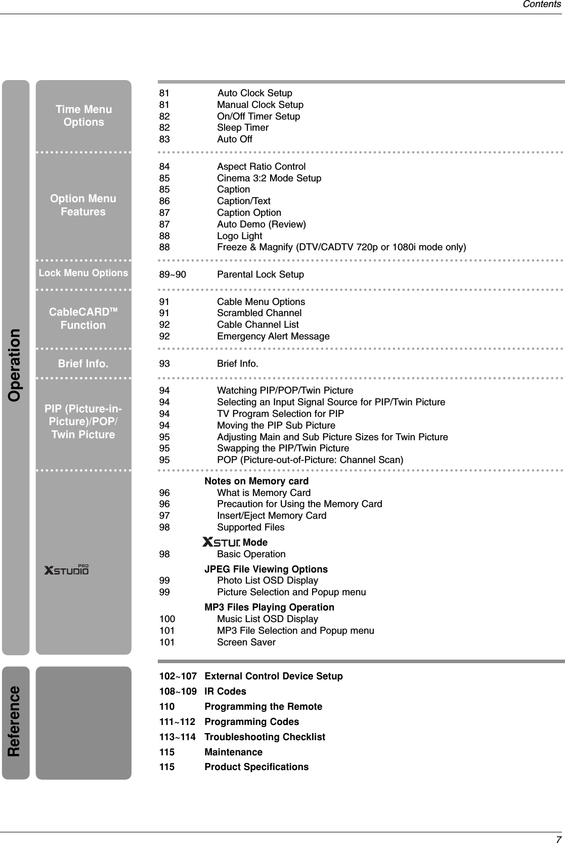
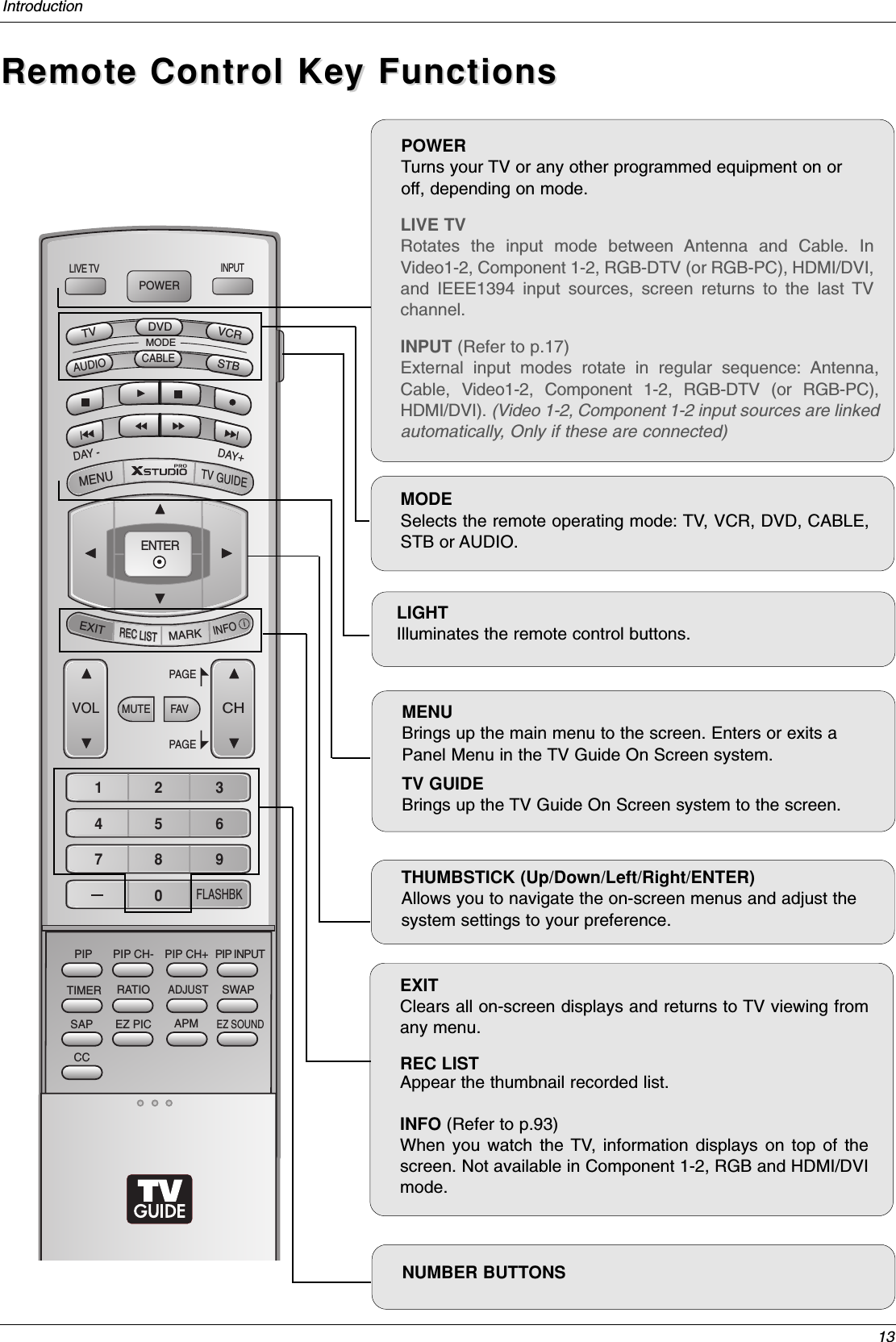
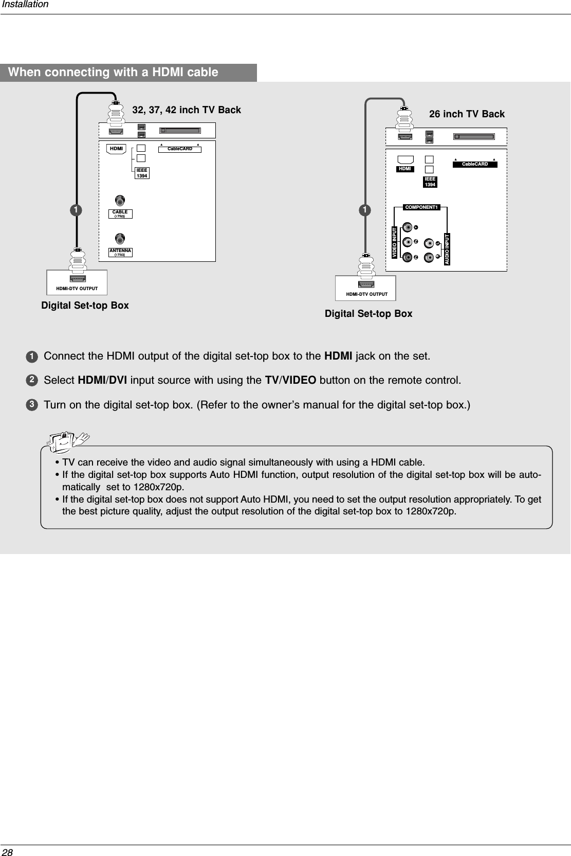
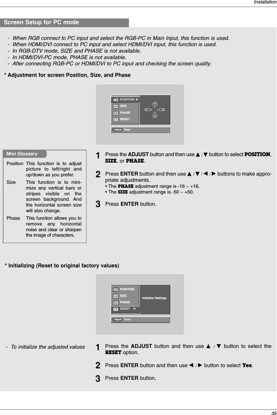
![108Reference19. Color Temperature (Command2:u)GTo adjust color temperature.You can also adjust color temperature in the Videomenu.TransmissionData 0: Medium 1: Cool 2: Warm[k][u][ ][Set ID][ ][Data][Cr]Acknowledgement[u][ ][Set ID][ ][OK][Data][x]21. Channel Tuning (Command: m a)GTo tune channel to following physical/major/minor numberTransmissionData 0: Physical channel number (Transmit by Hexadecimal code)* NTSC air: 02 ~ 45NTSC cable: 01, 0E ~ 7DATSC air: 01 ~ 45ATSC cable: 01 ~ 87Data1, 2: Major channel number(two part)/channel number(One part)* Data1: High byteData2: Low byteTwo part channel number: Major number-Minor numberOne part channel number: If the channel band is ATSCdigital cable, it can be used. In case of using one partchannel number, minor channel does not need.Data 3, 4: Minor Channel Number* Data3: High byte* Data4: Low byteData 5:* All data are transmitted by Hexadecimal code* Two/One part Channel: 6th bitThis bit is used in a cable-ready system. *Using physical channel: 5th bitIf the channel band is NTSC air or NTSC cable, channel tun-ing can be done by only physical channel. In this case, usingphysical channel bit must be low(0).But if the channel band is ATSC air or ATSC cable, there aretwo cases that physical channel enable or disable.If the physical channel sending is meaningful, you should setthis bit low(0). If the physical channel sending is meaningless,you should set this bit high(1).Example)1. Analog channel: NTSC cable, channel number(35), mainpictureCommand: ma 00 23 xx xx xx xx 01attribute(0x01): main picture, two part(it’s not mandatory),using physical channel, NTSC cable‘xx’data: don’t care major and minor channel number incase analog channel tuning2. Digital channel: ATSC air, channel number(don’t knowphysical channel, major(30), minor(3)), sub pictureCommand: ma 00 xx 00 1E 00 03 A2attribute(0xA2): sub picture, two part, not using physicalchannel, ATSC air‘xx’data: don’t care analog channel number in case digitalchannel tuning.3. Digital channel: ATSC air, channel number(physical(20),major(30), minor(3)), sub pictureCommand: ma 00 14 00 1E 00 03 82attribute(0x82): sub picture, two part, using physical chan-nel, ATSC air[a][ ][Set ID][ ][OK][Data0][Data1][Data2][Data3][Data4][Data5][x][a][ ][Set ID][ ][NG][Data0][x][m][a][ ][Set ID][ ][Data0][ ][Data1][ ][Data2][ ][Data3][ ][Data4][ ][Data5][Cr]Acknowledgement22. Channel Add/Del (Command: m b)GTo add and delete the channelsTransmissionData 0: Channel Delete1: Channel Add[m][b][ ][Set ID][ ][Data][Cr][b][ ][Set ID][ ][OK][Data][x][b][ ][Set ID][ ][NG][Data][x]Acknowledgement23. Key (Command: m c)GTo send IR remote key codeTransmissionData Key code: See page 109.[m][c][ ][Set ID][ ][Data][Cr][c][ ][Set ID][ ][OK][Data][x]Acknowledgement20. PIP Input Select (Command2:y)G To select input source for sub picture in PIP/Twin pic-ture mode.TransmissionData 0: DTV1: Analog2: Video 13: Video 2[k][y][ ][Set ID][ ][Data][Cr]Acknowledgement[y][ ][Set ID][ ][OK][Data][x]StepNTSC AirNTSC CableATSC AirATSC cable_stdATSC cable_hrcATSC cable_ircATSC cable autoReserved…Reserved001010101x1100110011x1200001111x1300000000x14Reservedxxxxxxxxxx601501701Two/OnePartChannelTwoOneUsingPhysicalChannelUseNo UseMain/Sub PictureMain Sub](https://usermanual.wiki/LG-Electronics-USA/50PC1DRAUA/User-Guide-603659-Page-25.png)
![109Reference24. Input Select (Command:x b) (Main Picture Input)G To select input source for TV.Transmission[x][b][ ][Set ID][ ][Data][Cr]Acknowledgement[b][ ][Set ID][ ][OK/NG][Data][x]25. PIP Input Select (Command:x y)GTo adjust the input source for sub picture in PIP modeTransmission[x][y][ ][Set ID][ ][Data][Cr]Acknowledgement[y][ ][Set ID][ ][OK/NG][Data][x]DTV (Antenna) 00DTV (Cable) 01Analog (Antenna) 10Analog (Cable) 11Video 1 20Video 2 21Component 1 40Component 2 41RGB-DTV 50RGB-PC 60HDMI/DVI 90DATA(Hex)INPUTDTV (Antenna) 00DTV (Cable) 01Analog (Antenna) 10Analog (Cable) 11Video 1 20Video 2 21DATA(Hex)INPUTData StructureData Structure](https://usermanual.wiki/LG-Electronics-USA/50PC1DRAUA/User-Guide-603659-Page-26.png)