LG Electronics USA 50PC1DRAUA Plasma Display User Manual U512Aen
LG Electronics USA Plasma Display U512Aen
Users Manual
LCD TV
Please read this manual carefully before operating your set.
Retain it for future reference.
Record model number and serial number of the set.
See the label attached on the back cover and quote
this information to your dealer
when you require service.
P/NO : 38289U0512A
OWNER’S MANUAL
MODELS: 42LB1DR 42LB1DRA
TM
PLASMA TV
OWNER’S MANUAL
MODELS: 50PC1DR 50PC1DRA
50PC1DR-UA 50PC1DRA-UA
2
Warning
WARNING:
TO REDUCE THE RISK OF ELECTRIC SHOCK DO NOT REMOVE COVER (OR BACK). NO USER
SERVICEABLE PARTS INSIDE. REFER TO QUALIFIED SERVICE PERSONNEL.
The lightning flash with arrowhead symbol, within an equilateral triangle, is intended to alert the user to
the presence of uninsulated “dangerous voltage” within the product’s enclosure that may be of suffi-
cient magnitude to constitute a risk of electric shock to persons.
The exclamation point within an equilateral triangle is intended to alert the user to the presence of
important operating and maintenance (servicing) instructions in the literature accompanying the appli-
ance.
NOTE TO CABLE/TV INSTALLER:
This reminder is provided to call the CATV system installer’s attention to Article 820-40 of the National Electric
Code (U.S.A.). The code provides guidelines for proper grounding and, in particular, specifies that the cable
ground shall be connected to the grounding system of the building, as close to the point of the cable entry as prac-
tical.
REGULATORY INFORMATION
This equipment has been tested and found to comply with the limits for a Class B digital device, pursuant to Part
15 of the FCC Rules. These limits are designed to provide reasonable protection against harmful interference in
a residential installation. This equipment generates, uses and can radiate radio frequency energy and, if not
installed and used in accordance with the instructions, may cause harmful interference to radio communications.
However, there is no guarantee that interference will not occur in a particular installation. If this equipment does
cause harmful interference to radio or television reception, which can be determined by turning the equipment off
and on, the user is encouraged to try to correct the interference by one or more of the following measures:
- Reorient or relocate the receiving antenna.
- Increase the separation between the equipment and receiver.
- Connect the equipment into an outlet on a circuit different from that to which the receiver is connected.
- Consult the dealer or an experienced radio/TV technician for help.
Any changes or modifications not expressly approved by the party responsible for compliance could void the
user’s authority to operate the equipment.
CAUTION:
Do not attempt to modify this product in any way without written authorization from LG Electronics Corporation.
Unauthorized modification could void the user’s authority to operate this product.
U.S.A. only -----------------------------------------------
COMPLIANCE:
The responsible party for this product’s compliance is:
LG Electronics U.S.A., Inc.
1000 Sylvan Avenue, Englewood Cliffs, NJ 07632
Phone: 1-201-816-2000
http://www.lgusa.com
---------------------------------------------------------------
CAUTION
RISK OF ELECTRIC SHOCK
DO NOT OPEN
W
Warning
arning
3
Safety Instructions
WARNING :
To Reduce The Risk Of Fire Or Electric Shock, Do Not Expose This Apparatus To Rain Or Moisture.
Apparatus shall not be exposed to dripping or splashing and no objects filled with liquids, such as vases, shall be placed on the
apparatus.
IMPORTANT SAFETY INSTRUCTIONS
1. Read these instructions.
2. Keep these instructions.
3. Heed all warnings.
4. Follow all instructions.
5. Do not use this apparatus near water.
6. Clean only with a dry cloth.
7. Do not block any of the ventilation openings. Install in
accordance with the manufacturer’s instructions.
8. Do not install near any heat sources such as radiators,
heat registers, stoves, or other apparatus (including
amplifiers) that produce heat.
9. Do not defeat the safety purpose of the polarized or
grounding type plug. A polarized plug has two blades
with one wider than the other. A grounding type plug has
two blades and a third grounding prong. The wide blade
or the third prong is provided for your safety. When the
provided plug does not fit into your outlet, consult an
electrician for replacement of the obsolete outlet.
10. Protect the power cord from being walked on or
pinched particularly at plugs, convenience recepta-
cles, and the point where they exit from the apparatus.
11. Only use the attachments / accessories specified by
the manufacturer.
Safety Instructions
Safety Instructions
Owner's Manual
44
Safety Instructions
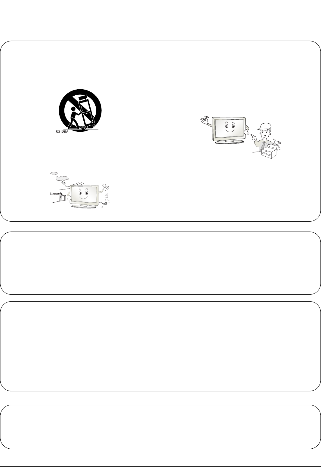
12. Use only with a cart, stand, tripod, bracket, or table
specified by the manufacturer, or sold with the appa-
ratus. When a cart is used, use caution when moving
the cart / apparatus combination to avoid injury from
tip-over.
13. Unplug this apparatus during lightning storms or when
unused for long periods of time.
14. Refer all servicing to qualified service personnel.
Servicing is required when the apparatus has been
damaged in any way, such as power supply cord or
plug is damaged, liquid has been spilled or objects
have fallen into the apparatus, the apparatus has been
exposed to rain or moisture, does not operate normal-
ly, or has been dropped.
On Disposal
a. The fluorescent lamp used in this product contains a small amount of mercury.
b. Do not dispose of this product with general household waste.
Disposal of this product must be carried out in accordance to the regulations of your local authority.
Note
- If the TV feels cold to the touch, there may be a small “flicker” when when it is turned on. This is normal, there is noth-
ing wrong with TV.
- Some minute dot defects may be visible on the screen, appearing as tiny red, green, or blue spots. However, they have
no adverse effect on the monitor's performance.
- Avoid touching the LCD screen or holding your finger(s) against it for long periods of time. Doing so may produce some
temporary distortion effects on the screen.
CAUTION concerning the Power Cord
Most appliances recommend they be placed upon a dedicated circuit; that is, a single outlet circuit which powers only that
appliance and has no additional outlets or branch circuits. Check the specification page of this owner's manual to be certain.
Do not overload wall outlets. Overloaded wall outlets, loose or damaged wall outlets, extension cords, frayed power cords,
or damaged or cracked wire insulation are dangerous. Any of these conditions could result in electric shock or fire.
Periodically examine the cord of your appliance, and if its appearance indicates damage or deterioration, unplug it, discon-
tinue use of the appliance, and have the cord replaced with an exact replacement part by an authorized servicer.
Protect the power cord from physical or mechanical abuse, such as being twisted, kinked, pinched, closed in a door, or
walked upon. Pay particular attention to plugs, wall outlets, and the point where the cord exits the appliance.
5
TV Guide On Screen Notices for U.S.A.
TV Guide On Screen Notices for U.S.A.
Digital Cable Compatibility
Digital Cable Compatibility
This digital television is capable of receiving basic analog, digital basic and digital premium cable television
programming by direct connection to a cable system providing such programming. A security card provided
by your cable operator is required to view encrypted digital programming. Cable operator enhanced program
(For example, electronic program guide provided by the cable operator), and data enhanced television ser-
vice may require the use of a set top box. For more information contact your local cable operator.
Official term for an HDTV that conforms to the plug-and-play digital cable TV standard using POD (point
of deployment) access cards, also called CableCARDs.
Users can plug the cable directly into an HDTV set, then enjoy HDTV and digital cable without having to
use a separate set-top box.
Manufactured under license from Dolby Laboratories. “Dolby” and the double-D
symbol are trademarks of Dolby Laboratories.
is a trademark of SRS Labs, Inc.
TruSurround XT technology is incorporated under license from SRS Labs, Inc.
Manufactured under license from Dolby Laboratories. “Dolby” and the double-D symbol are trademarks
of Dolby Laboratories.
R
TruSurround XT
TM
HDMITM, the HDMI logo and High-Definition Multimedia Interface is a trademark or registered trademark of
HDMI Licensing."
High-definition television. High-resolution digital television broadcast and playback system composed of
roughly a million or more pixels, 16:9 aspect-ratio screens, and AC3 digital audio. A subset of digital
television, HDTV formats include 1080i and 720p resolution.
LG's own special digital image generator. It consists of full digital image processor, APM mode & 6
different main picture quality factors.
R
TruSurround XT
In the United States, TV GUIDE and other related marks are registered marks of Gemstar-TV Guide
International, Inc. and/or one of its affiliates. In Canada, TV GUIDE is a registered mark of Transcontinental
Inc., and is used under license by Gemstar-TV Guide International, Inc.
The TV Guide On Screen system is protected by one or more of the following issued United States patents
6,498,895, 6,418,556, 6,331,877; 6,239,794; 6,154,203; 5,940,073; 4,908,713; 4,751,578; 4,706,121.
The TV Guide On Screen system is manufactured under license from Gemstar-TV Guide International, Inc.
and/or one of its affiliates.
Use of the CableCARDTM TradeMark.
“CableCARDTM is a trademark of Cable Television Laboratories, Inc.”
Trademark Notice
License Notice
Patent Notice
Manufactured under license from BBE Sound, Inc.
6
Contents
Contents
Contents
Introduction
Installation
Operation
69 Turning on the TV
69 Volume Adjustment
69 Channel Selection
69 On Screen Menus Language Selection
70 On Screen Menus Selection and Adjustment
71 EZ Scan (Channel Search)
71 Manual Scan
72 Channel Edit
73 DTV Signal Strength
73 Channel Label Setup
74 Main Picture Source Selection
74 Input Label
75 EZ Picture
75 APM (Adaptive Picture Mode)
76 Manual Picture Control (EZ Picture-Custom option)
76 Color Temperature Control
76 Video Reset
77 Audio Language
77 EZ SoundRite
78 EZ Sound
78 Manual Sound Control (EZ Sound-Custom option)
79 Stereo/SAP Broadcasts Setup
79 Front Surround
80 TV Speakers On/Off Setup
80 BBE
2 Warnings
3 TV Guide On Screen Notices / Digital Cable Compatibility
4~5 Safety Instructions
8 Accessories
9 Controls (Model Name: 32/37/42LP1D)
10 Connection Options (Model Name: 32/37/42LP1D)
11 Controls (Model Name: 26/32LX1D, 26/32LX2D)
12 Connection Options (Model Name: 26LX1D/2D)
13 Connection Options (Model Name: 32LX1D/2D)
14~18 Remote Control Key Functions
19 Various Installation
20 How to use back cover
20 Swivel Stand (32/37/42LP1D, 26/32LX2D only)
21 Antenna or Cable Connection
22~23 VCR Setup
24~25 DVD Setup
26~29 HDSTB Setup
30 External AV Source Setup
30 Digital Audio Output
31 Monitor Out Setup (32LX1D/2D, 32/37/42LP1D only)
31 CableCARDTM Setup
32~35 PC Setup
36~41 IEEE1394
42~43 G-LINKTM Setup
44~50 TV Guide On ScreenTM System Setup
51~68 TV Guide On ScreenTM System Feature
Setup Menu
Options
Video Menu
Options
Audio Menu
Options
Basic operation
External
Equipment
Connections
Installation
Instruction

7
Contents
Reference
81 Auto Clock Setup
81 Manual Clock Setup
82 On/Off Timer Setup
82 Sleep Timer
83 Auto Off
84 Aspect Ratio Control
85 Cinema 3:2 Mode Setup
85 Caption
86 Caption/Text
87 Caption Option
87 Auto Demo (Review)
88 Logo Light
88 Freeze & Magnify (DTV/CADTV 720p or 1080i mode only)
89~90 Parental Lock Setup
91 Cable Menu Options
91 Scrambled Channel
92 Cable Channel List
92 Emergency Alert Message
93 Brief Info.
94 Watching PIP/POP/Twin Picture
94 Selecting an Input Signal Source for PIP/Twin Picture
94 TV Program Selection for PIP
94 Moving the PIP Sub Picture
95 Adjusting Main and Sub Picture Sizes for Twin Picture
95 Swapping the PIP/Twin Picture
95 POP (Picture-out-of-Picture: Channel Scan)
Notes on Memory card
96 What is Memory Card
96 Precaution for Using the Memory Card
97 Insert/Eject Memory Card
98 Supported Files
Mode
98 Basic Operation
JPEG File Viewing Options
99 Photo List OSD Display
99 Picture Selection and Popup menu
MP3 Files Playing Operation
100 Music List OSD Display
101 MP3 File Selection and Popup menu
101 Screen Saver
102~107 External Control Device Setup
108~109 IR Codes
110 Programming the Remote
111~112 Programming Codes
113~114 Troubleshooting Checklist
115 Maintenance
115 Product Specifications
Option Menu
Features
Lock Menu Options
PIP (Picture-in-
Picture)/POP/
Twin Picture
CableCARDTM
Function
Brief Info.
Operation
Time Menu
Options
8
Introduction
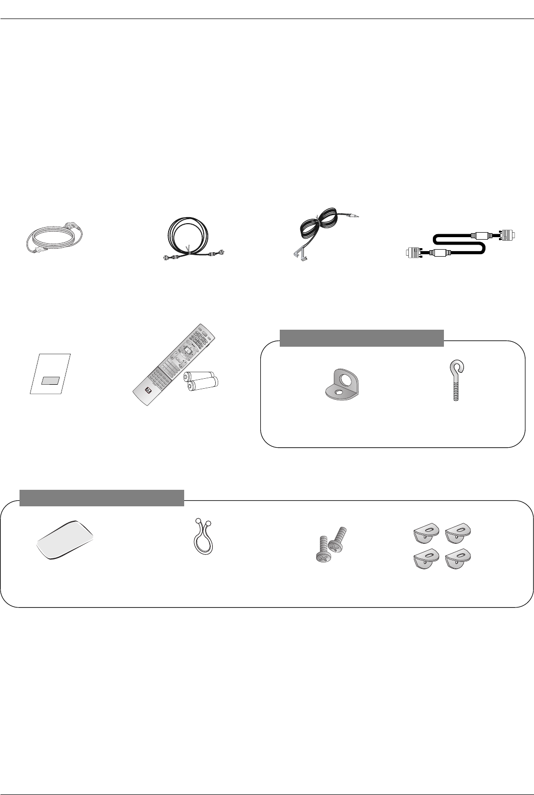
Accessories
Accessories
Introduction
Introduction
Owner’s Manual
75ΩRound Cable G-LINK CablePower Cord
Polishing Cloth
Polish the screen with the cloth.
Ensure that the following accessories are included with your TV. If any accessory is missing, please contact the
dealer from where you purchased the product.
1.5V
1.5V
TV INPUT
TV/VIDEO
VOL
FLASHBK
CH
POWER
1 2 3
456
78
0
9
ADJUST
RATIO SWAP
TIMER
PIP CH+PIP CH-
PIP
SAP
CC
M/C EJECT
FREEZE
AUTO DEMO
EZ PIC APM
EZ SOUND
PIP INPUT
AUDIO
DAY -
CABLE
MENU
MUTE
PAGE
PAGE
FAV
TV GUIDE
VCR
DAY+
STB
EXIT
1394
MARK
TV
DVD
MODE
INFO
i
ENTER
Remote Control /
Batteries
Twister Holder
Arrange the wires
with the twister holder.
D-sub 15 pin cable
2-Wall brackets 2-eye-bolts
2-TV Bracket Bolts
42LB1DR / 42LB1DRA Only
2-TV Brackets,
2-Wall Brackets
50PC1DR / 50PC1DRA Only
9
Introduction
Controls
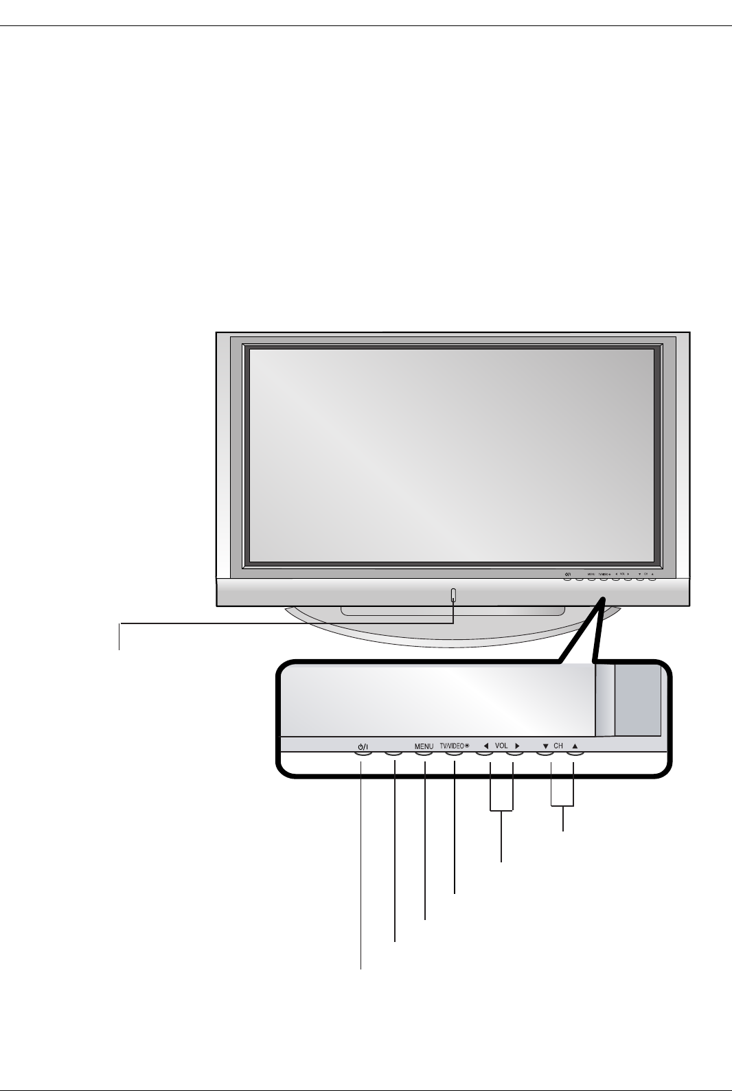
Controls (Model Name: 50PC1DR/50PC1DRA)
(Model Name: 50PC1DR/50PC1DRA)
- This is a simplified representation of front panel.
- Here shown may be somewhat different from your TV.
TV GUIDE
TV GUIDE
TV GUIDE
MENU Button
TV/VIDEO Button
VOLUME (FF,GG) Buttons
CHANNEL (EE, DD) Buttons
TV GUIDE Button
POWER Button
Front Panel Controls
Front Panel Controls
Remote Control Sensor/Power
Standby Indicator
Illuminates red when the TV is in
standby mode.
When the TV is switched on, blinks
green and then illuminates green.
10
Introduction
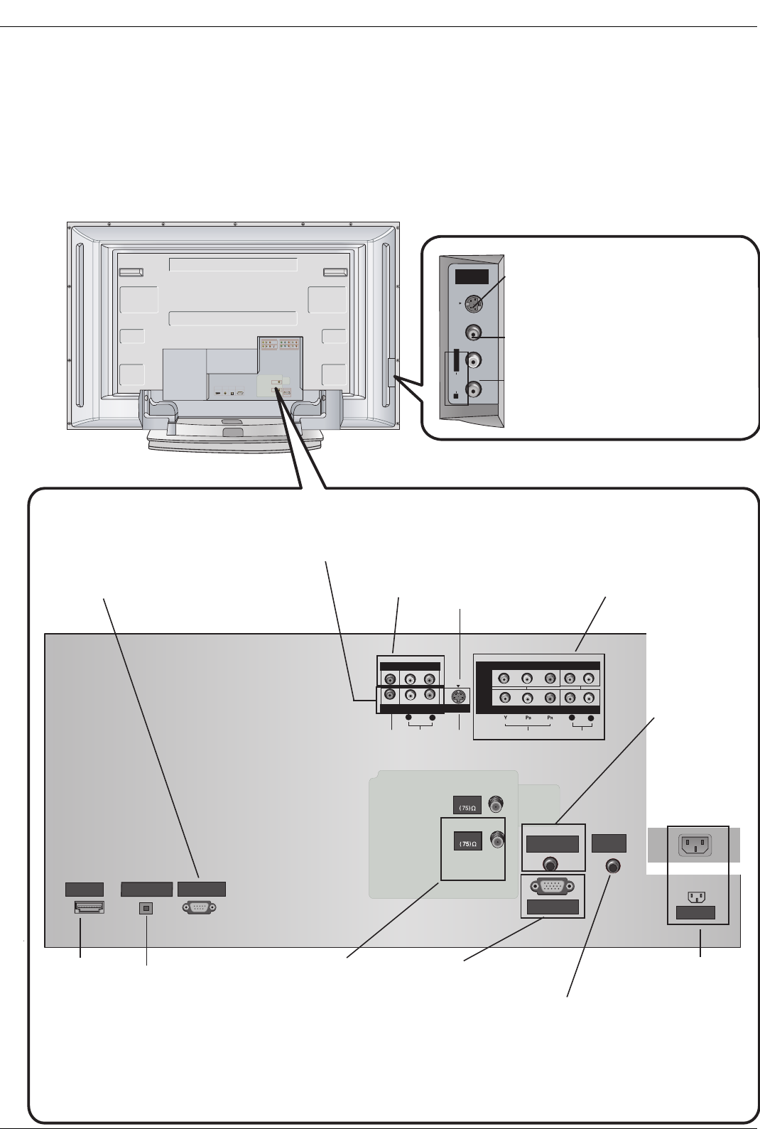
Connection Options (Model Name:
Connection Options (Model Name: 50PC1DR
50PC1DR / 50PC1DRA
/ 50PC1DRA)
)
- Here shown may be somewhat different from your TV.
HDMI/D VI 입력
HUPGRA DE
(MODULE)
디지털음성출력
UPGRA DE
안테나
케이블
음성(RGB/D VI)
RGB 입력
AV입력
AV출력
S-영상
컴포넌트 입력2
컴포넌트 입력1
영상 음성
Y P
R
좌 우 P
B
RS-VIDEO VIDEO
L / MONO
AUDIO
FRONT
A/V INPUT
HDMI /DVI IN
DIGITAL AUDIO
OPTICAL OUTPUT
(CONTROL/SERVICE)
RS-232C INPUT
AUDIO
R
L
VIDEO
COMPONENT INPUT 1
R
L
(MONO)
DVD
/DTV
INPUT
COMPONENT INPUT 2
MONITOR OUTPUT
A/V INPUT
VIDEO
AUDIO
S-VIDEO
RGB/DVI AUDIO
INPUT
REMOTE
CONTROL
AC INPUT
RGB INPUT
CABLE
ANTENNA
S-VIDEO Input
A connection available to provide bet-
ter picture quality than the video input.
VIDEO Input
Connects the video signal from a
video device.
AUDIO Input
Use to connect to hear stereo sound
from an external device.
Antenna Input
Connect over-the-
air signals to this
jack.
CABLE Input
Connect cable sig-
nals to this jack.
RGB INPUT
Connect the monitor
output connector
from a PC to the
appropriate input
port.
Digital Audio Output
Connect digital audio
from various types of
equipment.
Note: In standby
mode,
this port will not work.
DVD/DTV Input
(Component 1-2)
Connect a component
video/audio device to
these jacks.
Remote
Control Port
Connect your
wired remote
control here.
S-Video Input
Connect S-Video out
from an S-VIDEO
device to the S-
VIDEO input.
RS-232C INPUT (CON-
TROL/SERVICE) PORT
Connect to the RS-
232C port on a PC.
HDMI/DVI
(VIDEO)INPUT
connect a
DVI(Video) sig-
nal to HDMI/DVI.
Audio/Video Input
Connect audio/video
output from an
external device to
these jacks.
Back Connection Panel
Back Connection Panel
Power Cord Socket
This TV operates on
an AC power. The
voltage is indicated on
the Specifications
page. Never attempt
to operate the TV on
DC power.
Monitor
Output
Connect a
second TV or
Monitor.
RGB/DVI
AUDIO
INPUT
In RGB input
or DVI input,
this port sup-
plies Analog
audio.
13
Introduction
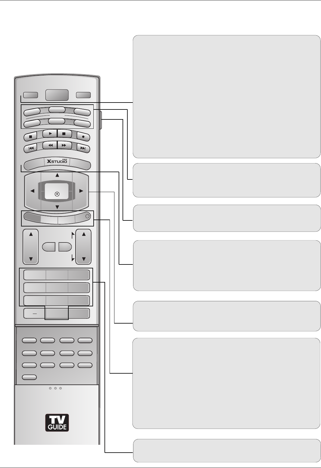
Remote Control Key Functions
Remote Control Key Functions
POWER
Turns your TV or any other programmed equipment on or
off, depending on mode.
LIVE TV
INPUT
VOL
FLASHBK
CH
POWER
1 2 3
4 5 6
78
0
9
ADJUST
RATIO SWAP
TIMER
PIP CH+PIP CH-
PIP
SAP
CC
EZ PIC APM
EZ SOUND
PIP INPUT
AUDIO
DAY -
CABLE
MENU
MUTE
PAGE
PAGE
FAV
TV GUIDE
VCR
DAY+
STB
EXIT
REC LISTREC LIST
MARK
TV
DVD
MODE
INFO
i
ENTER
LIVE TV
Rotates the input mode between Antenna and Cable. In
Video1-2, Component 1-2, RGB-DTV (or RGB-PC), HDMI/DVI,
and IEEE1394 input sources, screen returns to the last TV
channel.
MODE
Selects the remote operating mode: TV, VCR, DVD, CABLE,
STB or AUDIO.
INPUT (Refer to p.17)
External input modes rotate in regular sequence: Antenna,
Cable, Video1-2, Component 1-2, RGB-DTV (or RGB-PC),
HDMI/DVI). (Video 1-2, Component 1-2 input sources are linked
automatically, Only if these are connected)
EXIT
Clears all on-screen displays and returns to TV viewing from
any menu.
REC LIST
Appear the thumbnail recorded list.
INFO (Refer to p.93)
When you watch the TV, information displays on top of the
screen. Not available in Component 1-2, RGB and HDMI/DVI
mode.
MENU
Brings up the main menu to the screen. Enters or exits a
Panel Menu in the TV Guide On Screen system.
TV GUIDE
Brings up the TV Guide On Screen system to the screen.
THUMBSTICK (Up/Down/Left/Right/ENTER)
Allows you to navigate the on-screen menus and adjust the
system settings to your preference.
NUMBER BUTTONS
LIGHT
Illuminates the remote control buttons.
14
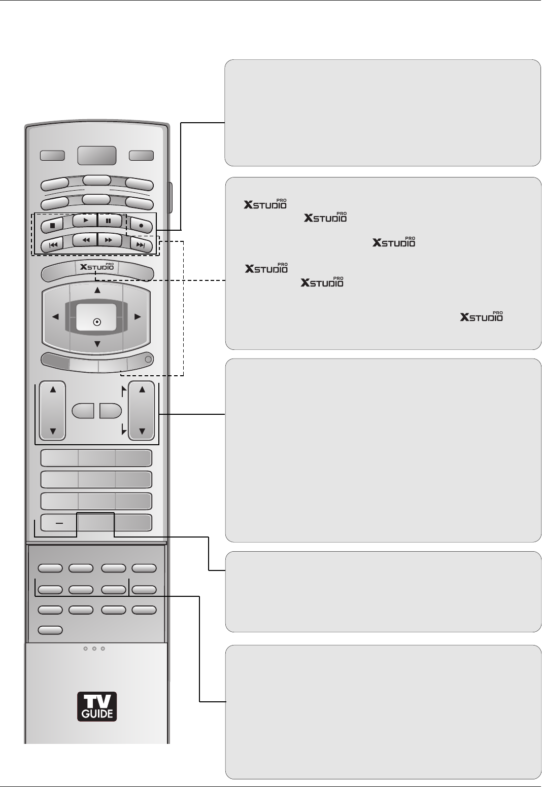
Introduction
TIMER (Refer to p.82)
Lets you select the amount of time before your TV turns
itself off automatically.
RATIO (Refer to p.84)
Changes the aspect ratio.
ADJUST (Refer to p.35)
Adjusts screen position, size, and phase in PC mode.
FAV
Use to scroll the Favorite channels.
MUTE (Refer to p.18)
Switches the sound on or off.
CHANNEL UP/DOWN
Selects available channels found with EZ scan and Manual scan.
PAGE UP/DOWN
Moves from one full set of screen information to the next one.
VOLUME UP/DOWN
Increases/decreases the sound level.
LIVE TV
INPUT
VOL
FLASHBK
CH
POWER
1 2 3
4 5 6
78
0
9
ADJUST
RATIO SWAP
TIMER
PIP CH+PIP CH-
PIP
SAP
CC
EZ PIC APM
EZ SOUND
PIP INPUT
AUDIO
DAY -
CABLE
MENU
MUTE
PAGE
PAGE
FAV
TV GUIDE
VCR
DAY+
STB
EXIT
REC LISTREC LIST
MARK
TV
DVD
MODE
INFO
i
ENTER
Mode Control Buttons
Controls the Mode.
Use for DVR record or trick play.
For further details, see the ‘’or ‘DVR’section.
— (DASH)
Used to enter a program number for multiple program chan-
nels such as 2-1, 2-2,etc.
FLASHBK
Returns to the last channel viewed.
VCR/DVD BUTTONS
Controls some video cassette recorders or DVD players
when you have already selected DVD or VCR mode
button.
DAY + / DAY-
Moves forward or backward in 24 hour increments.
Enter to the Mode.
MARK
Selects a recorded lists you want to view or play in
mode.
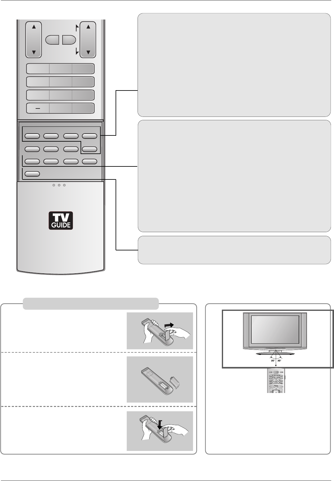
15
CC (Refer to p.86)
Select a closed caption: Off, CC1~4, Text1~4.
VOL
FLASHBK
CH
1 2 3
4 5 6
78
0
9
ADJUST
RATIO SWAP
TIMER
PIP CH+PIP CH-
PIP
SAP
CC
EZ PIC APM
EZ SOUND
PIP INPUT
MUTE
PAGE
PAGE
FAV
REC LIST
PIP (Refer to p.94)
Switches between PIP, POP (Picture-out-of-Picture) and
Twin picture modes. Switches the video window locking or
unlocking in the Listings Grid.
PIP CH-/PIP CH+ (Refer to p.94)
Changes to next higher/lower PIP channel.
PIP INPUT (Refer to p.94)
Selects the input source for the sub picture in PIP/Twin pic-
ture mode.
SWAP (Refer to p.95)
Exchanges the main/sub images in PIP/Twin picture mode.
SAP (Refer to p.79)
Selects MTS sound: Mono, Stereo, and SAP in analog mode.
Change the audio language in DTV mode.
EZ PIC (Refer to p.75)
Selects a factory preset picture mode depending on the view-
ing environment.
APM (Refer to p.75)
Concurrently, compare with the Daylight, Normal, Night Time
and Custom on the screen.
EZ SOUND (Refer to p.78)
Selects the sound appropriate for the program's character.
Introduction
Installing Batteries
Open the battery compartment
cover on the back side.
Insert two batteries in correct
polarity (+ with +, - with -). Don’t
mix old or used batteries with new
ones.
Close the cover.
* Use a remote control 7 meter distance
and 30 degree (left/right) within the
receiving unit scope.
* Dispose of used batteries in a recycle
bin to prevent environment.
TV INPUT
TV/VIDEO
POWER
AUDIO
DAY -
CABLE
MENU
TV GUIDE
VCR
DAY+
STB
TV
DVD
MODE
ENTER
1
2
3
i.e)
16
Introduction
LIVE TV
INPUT
VOL
FLASHBK
CH
POWER
1 2 3
4 5 6
78
0
9
ADJUST
RATIO SWAP
TIMER
PIP CH+PIP CH-
PIP
SAP
CC
EZ PIC APM
EZ SOUND
PIP INPUT
AUDIO
DAY -
CABLE
MENU
MUTE
PAGE
PAGE
FAV
TV GUIDE
VCR
DAY+
STB
EXIT
REC LIST
REC LIST
MARK
TV
DVD
MODE
INFO
i
ENTER
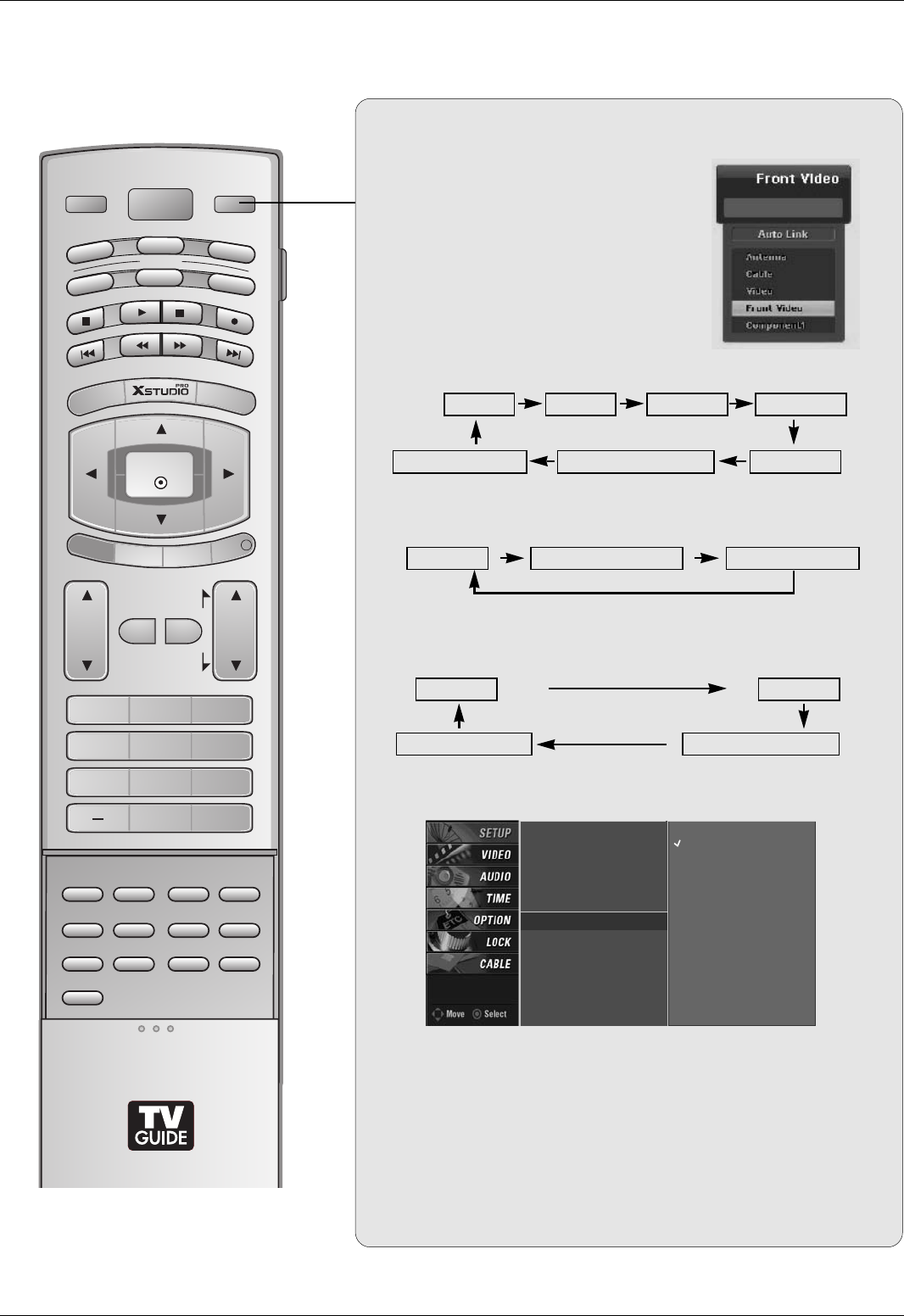
Auto Link
• You can also select Main Input in the SETUP menu.
• Antenna: Select it when watching the TV/DTV.
• Cable: Select it when watching the CATV/CADTV.
• Video,Front Video: Select it when watching the VCR or
external equipment.
• Component 1-2: Select it when using the DVD or the Digital
set-top box depend on connector.
• RGB-PC / RGB-DTV: Select it when using PC or Digital set-top
box depend on connector.
• HDMI / DVI, HDMI2: Select it when using DVD, PC or Digital
set-top box depend on connector.
1. When every external equipment is connected:
2. When any external equipment is not connected:
TV Video Front Video Component1
HDMI/DVI and HDMI2 Component2RGB-DTV (or RGB-PC)
3. When some External Equipment is connected:
(ex: When connected to Video 2)
TV
RGB-DTV (or RGB-PC)
Front Video
HDMI/DVI and HDMI2
TV RGB-DTV (or RGB-PC) HDMI/DVI and HDMI2
• Only, display the connected external
equipment list on the screen.
(Not connected external equipment is
marked to deactivate.)
• At this time, if you press the ENTER
button, change the main input to the
active external equipment.
EZ Scan
Manual Scan
Channel Edit
DTV Signal
Main Input G
Sub Input
Input Label
Set ID
Antenna
Cable
Video
Front Video
Component1
Component2
RGB-PC
HDMI1/DVI
HDMI2
28
Installation
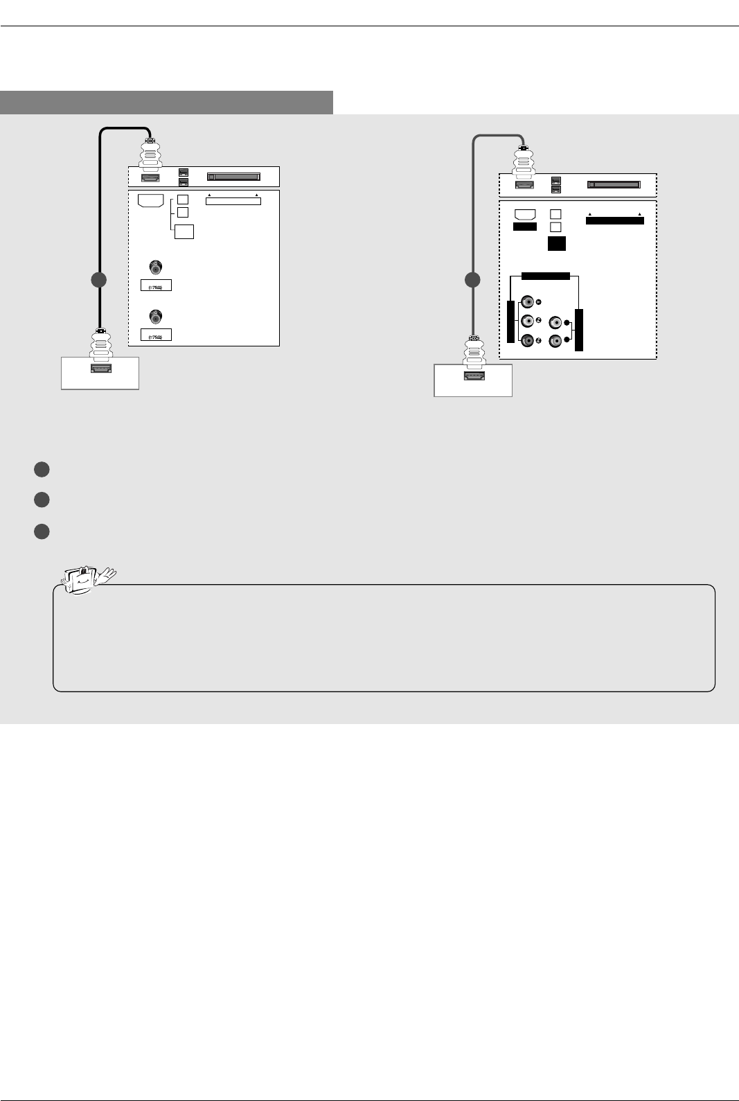
When connecting with a HDMI cable
1
2
3
Connect the HDMI output of the digital set-top box to the HDMI jack on the set.
Select HDMI/DVI input source with using the TV/VIDEO button on the remote control.
Turn on the digital set-top box. (Refer to the owner’s manual for the digital set-top box.)
ANTENNA
CableCARD
CABLE
HDMI-DTV OUTPUT
IEEE
1394
HDMI
HDMI-DTV OUTPUT
AUDIO INPUT
VIDEO INPUT
RL
CableCARD
IEEE
1394
HDMI
COMPONENT1
Digital Set-top Box Digital Set-top Box
1 1
•TV can receive the video and audio signal simultaneously with using a HDMI cable.
•If the digital set-top box supports Auto HDMI function, output resolution of the digital set-top box will be auto-
matically set to 1280x720p.
•If the digital set-top box does not support Auto HDMI, you need to set the output resolution appropriately. To get
the best picture quality, adjust the output resolution of the digital set-top box to 1280x720p.
32, 37, 42 inch TV Back 26 inch TV Back
29
Installation
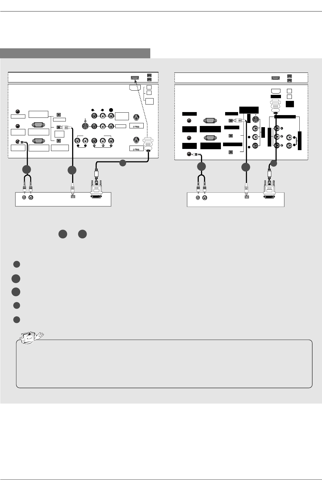
When connecting with a HDMI to DVI cable
1
4
5
Connect the DVI output of the digital set-top box to the HDMI jack on the set.
Connect the audio output of the digital set-top box to the PC AUDIO INPUT jack on the set.
Connect the optical audio output of the digital set-top box to the DIGITAL AUDIO DVI INPUT jack on the set.
Turn on the digital set-top box. (Refer to the owner’s manual for the digital set-top box.)
Select HDMI/DVI input source with using the TV/VIDEO button on the remote control.
(R) AUDIO (L) DIGITAL AUDIO
OPTICAL
DVI-DTV OUTPUT
ANTENNA
G-LINK
DIGITAL AUDIO
(OPTICAL)
DVI
INPUT
COMPONENT1
INPUT
OUTPUT
VIDEO1
RGB INPUT
(PC/DTV INPUT)
RS-232C INPUT
(CONTROL/SERVICE)
AUDIO INPUT
AUDIO
(MONO)
VIDEO INPUT
COMPONENT1
RL
RL
PC AUDIO
INPUT
REMOTE
CONTROL
S-VIDEO
CABLE
MONITOR
OUT
VIDEO
IEEE
1394
HDMI
(R) AUDIO (L) DIGITAL AUDIO
OPTICAL
DVI-DTV OUTPUT
G-LINK
DIGITAL AUDIO
(OPTICAL)
OUTPUT
VIDEO1
RGB INPUT
(PC/DTV INPUT)
RS-232C INPUT
(CONTROL/SERVICE PORT)
AUDIO INPUT
VIDEO INPUT
RL
PC AUDIO
INPUT
REMOTE
CONTROL
S-VIDEO
IEEE
1394
AUDIO VIDEO
(MONO)
RL
HDMI
DVI INPUT
COMPONENT1 INPUT
COMPONENT1
Digital Set-top Box Digital Set-top Box
1
2-1 2-2
1
2-1 2-2
Select or , depending on your digital set-top box connector.
2-1 2-2
• If the digital set-top box has a DVI output and no HDMI output, a separated audio connection is necessary.
•If the digital set-top box supports Auto DVI function, the output resolution of the digital set-top box will be auto-
matically set to 1280x720p.
•If the digital set-top box does not support Auto DVI, you need to set the output resolution appropriately. To get the
best picture quality, adjust the output resolution of the digital set-top box to 1280x720p.
2-1
2-2
32, 37, 42 inch TV Back 26 inch TV Back
33
Installation
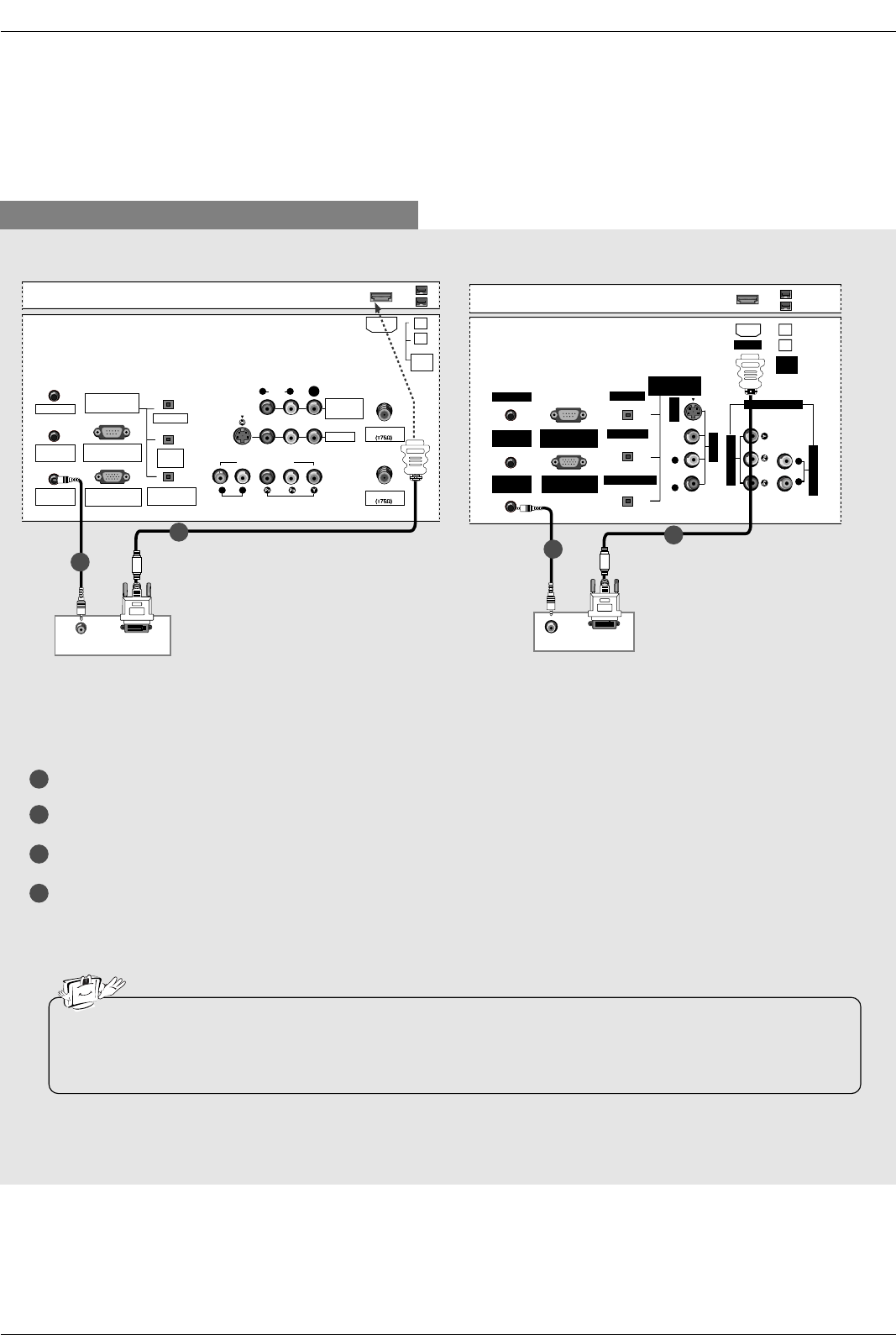
When connecting with a HDMI to DVI cable
1
2
3
4
Connect the DVI output of the PC to the HDMI jack on the set.
Connect the PC audio output to the PC AUDIO INPUT jack on the set.
Turn on the PC and the set.
Select HDMI/DVI input source with using the TV/VIDEO button on the remote control.
DVI-PC OUTPUT
AUDIO
ANTENNA
G-LINK
DIGITAL AUDIO
(OPTICAL)
DVI
INPUT
COMPONENT1
INPUT
OUTPUT
VIDEO1
RGB INPUT
(PC/DTV INPUT)
RS-232C INPUT
(CONTROL/SERVICE)
AUDIO INPUT
AUDIO
(MONO)
VIDEO INPUT
COMPONENT1
RL
RL
PC AUDIO
INPUT
REMOTE
CONTROL
S-VIDEO
CABLE
MONITOR
OUT
VIDEO
IEEE
1394
HDMI
AUDIO
DVI-PC OUTPUT
G-LINK
DIGITAL AUDIO
(OPTICAL)
OUTPUT
VIDEO1
RGB INPUT
(PC/DTV INPUT)
RS-232C INPUT
(CONTROL/SERVICE PORT)
AUDIO INPUT
VIDEO INPUT
RL
PC AUDIO
INPUT
REMOTE
CONTROL
S-VIDEO
IEEE
1394
AUDIO VIDEO
(MONO)
RL
HDMI
DVI INPUT
COMPONENT1 INPUT
COMPONENT1
PC PC
• If the PC has a DVI output and no HDMI output, a separated audio connection is necessary.
•If the PC does not support Auto DVI, you need to set the output resolution appropriately. To get the best picture
quality, adjust the output resolution of PC graphics card's output resolution to 1024x768, 60Hz.
32, 37, 42 inch TV Back 26 inch TV Back
1
2
1
2
34
Installation
1. To get the best picture quality, adjust the PC
graphics card to 1024x768, 60Hz.
2. Depending on the graphics card, DOS mode may
not work if a HDMI to DVI Cable is in use.
3. When Source Devices connected with HDMI/DVI
Input, output PC Resolution (VGA, SVGA, XGA),
Position and Size may not fit to Screen.Press the
ADJUST button to adjust the screen Position of TV
SET and contact an PC graphics card service cen-
ter.
4. When Source Devices connected with HDMI/DVI
Input, output TV SET Resolution (480p, 720p,
1080i) and TV SET Display fit EIA/CEA-861-B
Specification to Screen. If not, refer to the Manual
of HDMI/DVI Source Devices or contact your ser-
vice center.
5. In case HDMI/DVI Source Devices is not connect-
ed Cable or poor cable connection, "NO SIGNAL"
OSD display in HDMI/DVI Input. In case that Video
Resolution is not supported TV SET output in
HDMI/DVI Source Devices, "INVALID FORMAT"
OSD display. Refer to the Manual of HDMI1/DVI
Source Devices or contact your service center.
6. Check the image on your TV. There may be noise
associated with the resolution, vertical pattern,
contrast or brightness in PC, HDMI/DVI mode. If
noise is present, change the PC or HDMI/DVI
mode to another resolution, change the refresh
rate to another rate or adjust the brightness and
contrast on the menu until the picture is clear. If the
refresh rate of the PC graphic card can not be
changed, change the PC graphic card or consult
the manufacturer of the PC graphic card.
7. Avoid keeping a fixed image on the TV's screen for
a long period of time. The fixed image may become
permanently imprinted on the screen.
8. The synchronization input form for Horizontal and
Vertical frequencies is separate.
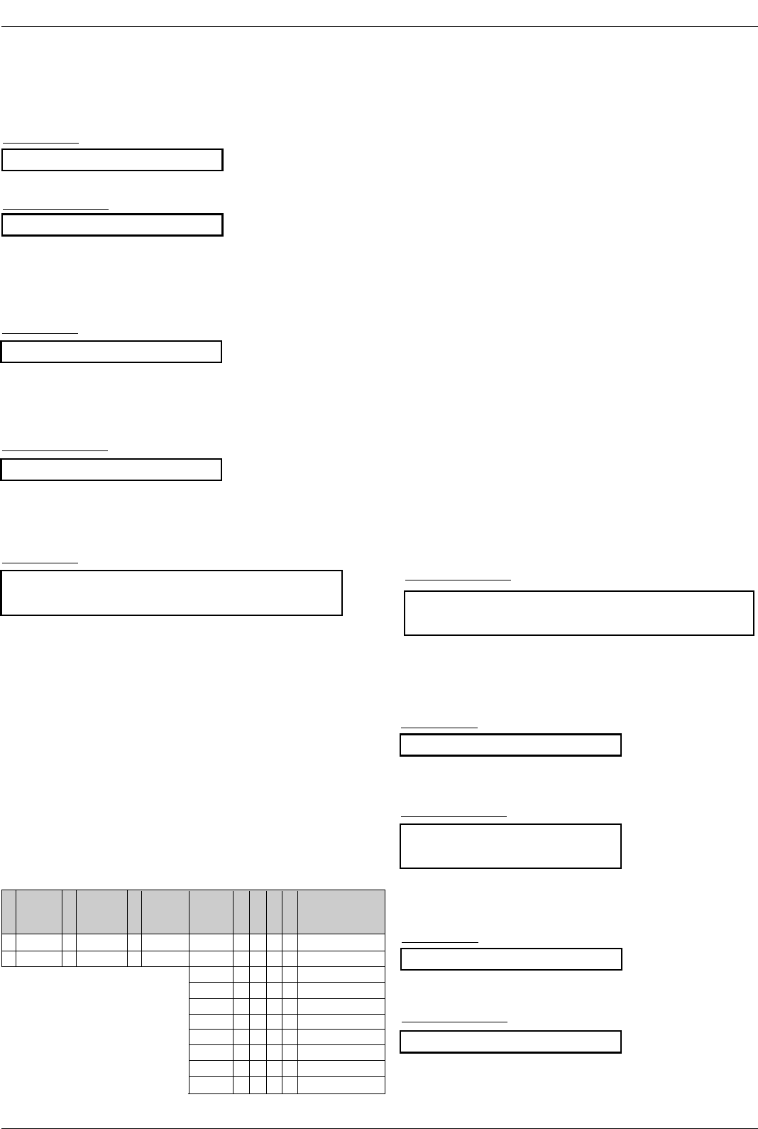
Supported Display Resolution
(RGB-PC, HDMI/DVI Mode)
Resolution
640x350
720x400
640x480
800x600
1024x768
Horizontal
Frequency (kHz)
31.468
31.469
31.469
37.861
37.500
35.156
37.879
48.077
46.875
48.363
56.476
60.023
60
60
70.09
70.08
59.94
72.80
75.00
56.25
60.31
72.18
75.00
60.00
70.06
75.02
60
60
Vertical
Frequency (Hz)
Supported Display Resolution
(RGB-DTV, HDMI/DVI Mode)
Resolution
1280x720p
1920x1080i
720x480p
Horizontal
Frequency (kHz)
45
33.75
31.5
60
60
60
Vertical
Frequency (Hz)
1280x768
1360x768
35
Installation
* Adjustment for screen Position, Size, and Phase
* Initializing (Reset to original factory values)
- To initialize the adjusted values
Close
POSITION GG
SIZE
PHASE
RESET
Adjust
DD
FFGG
EE
Close
POSITION
SIZE
PHASE
RESET GG
Adjust
Initialize Settings
Position This function is to adjust
picture to left/right and
up/down as you prefer.
Size This function is to mini-
mize any vertical bars or
stripes visible on the
screen background. And
the horizontal screen size
will also change.
Phase This function allows you to
remove any horizontal
noise and clear or sharpen
the image of characters.
Mini Glossary
- When RGB connect to PC input and select the RGB-PC in Main Input, this function is used.
- When HDMI/DVI connect to PC input and select HDMI/DVI input, this function is used.
- In RGB-DTV mode, SIZE and PHASE is not available.
- In HDMI/DVI-PC mode, PHASE is not available.
- After connecting RGB-PC or HDMI/DVI to PC input and checking the screen quality.
Press the ADJUST button and then use DD / EEbutton to select POSITION,
SIZE, or PHASE.
Press ENTER button and then use DD / EE/ FF / GG buttons to make appro-
priate adjustments.
• The PHASE adjustment range is -16 ~ +16.
• The SIZE adjustment range is -50 ~ +50.
Press ENTER button.
1
2
3
Press the ADJUST button and then use DD / EEbutton to select the
RESET option.
Press ENTER button and then use FF / GG button to select Yes.
Press ENTER button.
1
2
3
Screen Setup for PC mode
36
Operation
Operation
Operation
Basic operation
Basic operation
1. First, connect power cord correctly. At this moment, the TV switches to standby mode.
In standby mode to turn TV on, press the (or ON/OFF), INPUT, CH DD/ EEbutton on the TV or press the
POWER, INPUT, CH DD/ EE, Number (0 ~ 9) button on the remote control .
2. Select the viewing source by using INPUT button on the remote control.
This TV is programmed to remember which power state it was last set to, even if the power cord is out.
3. When finished using the TV, press the POWER button on the remote control. The TV reverts to standby mode.
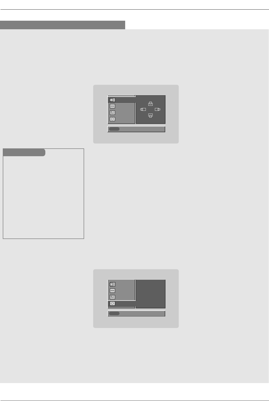
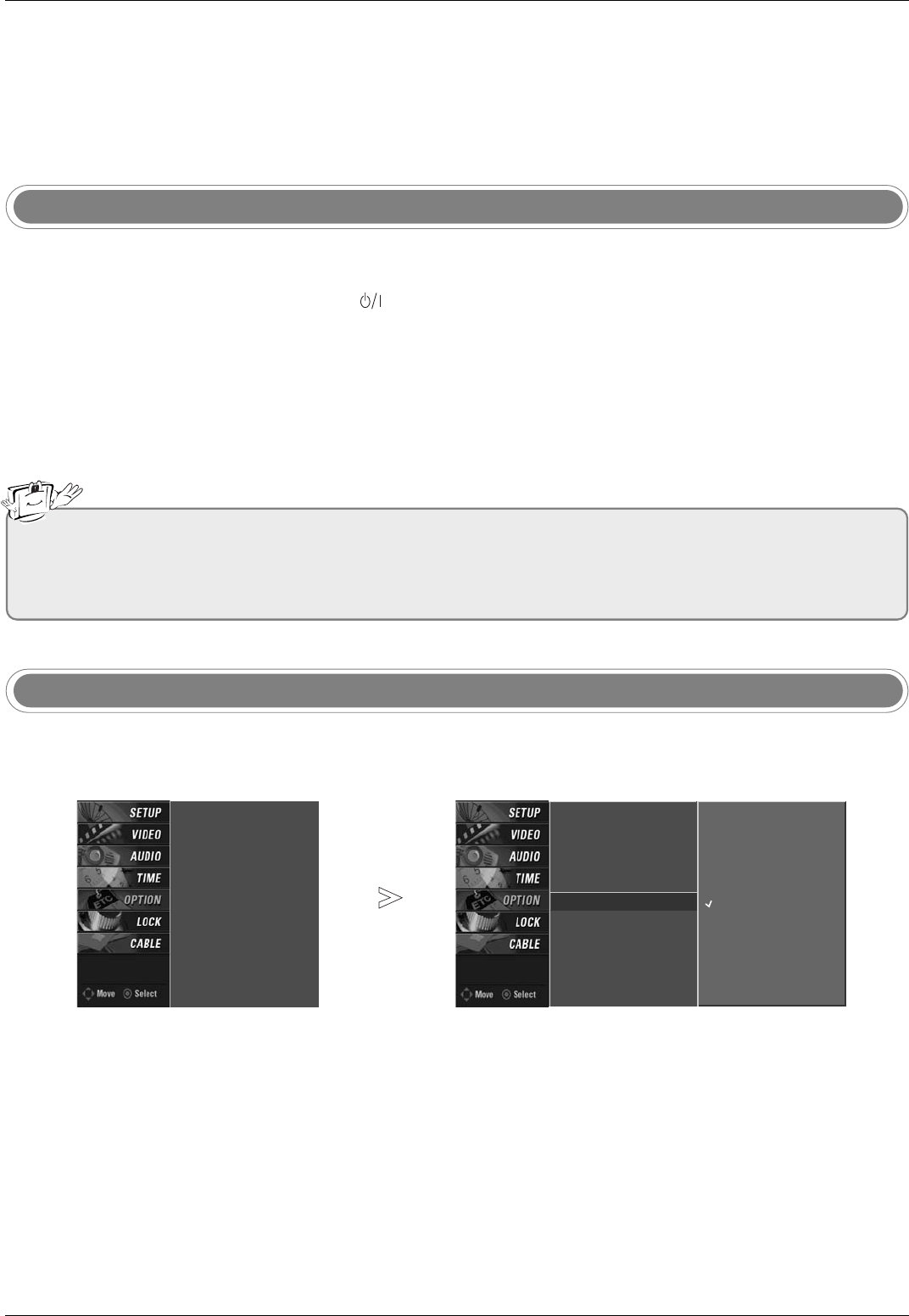
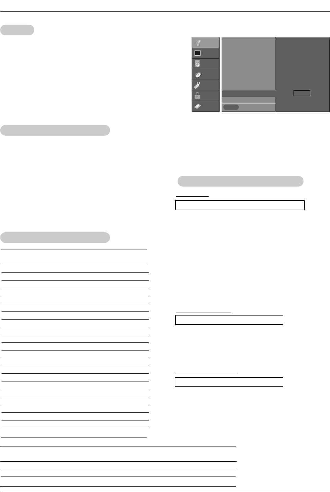
- The menus can be shown on the screen in the selected language. First select your language.
On Screen Menus Language Selection
Turning on the TV
Press the MENU button and then use DD/ EEbutton to select the OPTION menu.
Press the GGbutton and then use DD/ EEbutton to select Language.
Press the GGbutton and then use DD/ EEbutton to select your desired language. From this
point on, the on-screen menus will be shown in the selected language.
Press EXIT button to return to TV viewing or press MENU button to return to the previ-
ous menu.
1
2
3
4
• If you intend to be away on vacation, disconnect the power plug from the wall power outlet.
• After turning on the TV, it will take up to a week for the TV Guide On Screen system to receive full listings data.
• When the TV is turned On, the TV Guide On Screen system is automatically displayed. The screen may be slightly delayed
if the TV was unplugged and then powered On.
Timeshift Mode
Aspect Ratio
Caption/Text
Caption Option
Language G
HDD Format
English
Español (Spanish)
Français (French)
Timeshift Mode
Aspect Ratio
Caption/Text
Caption Option
Language
HDD Format
104
Reference
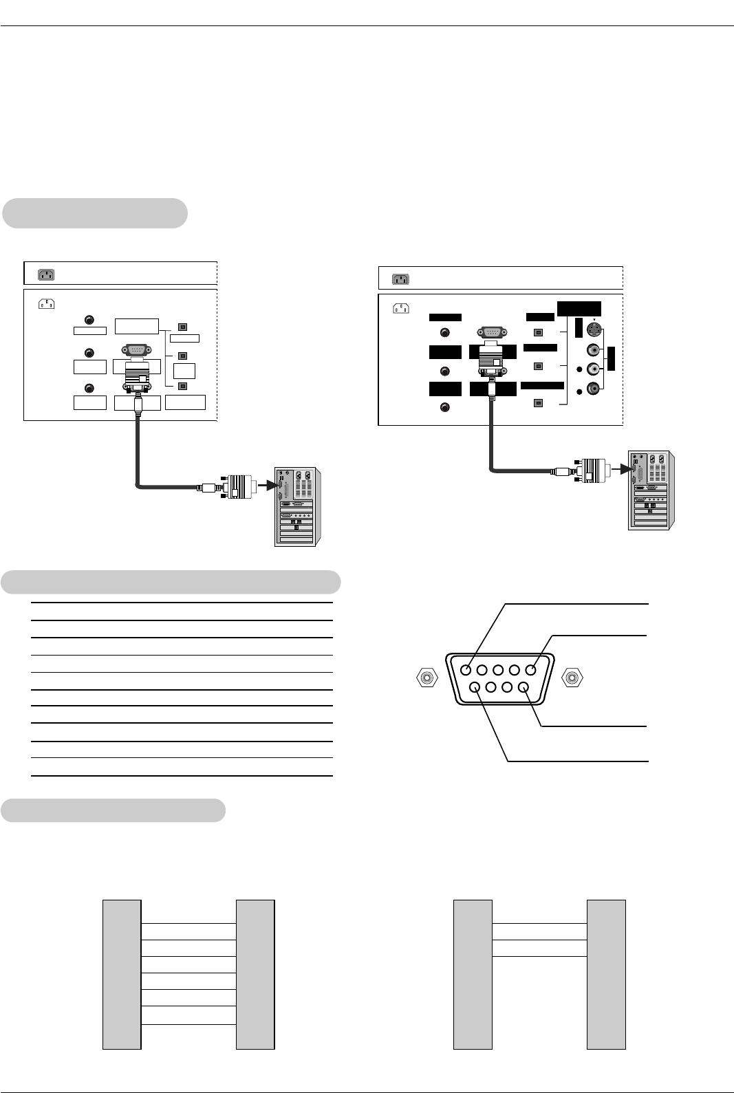
No. Pin Name
1 No connection
2 RXD (Receive data)
3 TXD (Transmit data)
4 DTR (DTE side ready)
5 GND
6 DSR (DCE side ready)
7 RTS (Ready to send)
8 CTS (Clear to send)
9 No Connection
1
5
6
9
2
3
5
4
6
7
8
RXD
TXD
GND
DTR
DSR
RTS
CTS
TXD
RXD
GND
DSR
DTR
CTS
RTS
PC
7-Wire Configurations
(Serial female-female NULL modem cable)
D-Sub 9
3
2
5
6
4
8
7
TV
D-Sub 9
2
3
5
4
6
7
8
RXD
TXD
GND
DTR
DSR
RTS
CTS
TXD
RXD
GND
DTR
DSR
RTS
CTS
PC
3-Wire Configurations
(Not standard)
D-Sub 9
3
2
5
4
6
7
8
TV
D-Sub 9
- Connect the RS-232C input jack to an external control device (such as a computer or an A/V control system) and
control the Monitor’s functions externally.
- Connect the serial port of the control device to the RS-232C jack on the TV back panel.
- RS-232C connection cables are not supplied with the TV.
T
Type of Connector; D-Sub 9-Pin Male
ype of Connector; D-Sub 9-Pin Male
RS-232C Configurations
RS-232C Configurations
External Control Device Setup
External Control Device Setup
RS-232C Setup
RS-232C Setup
AC IN
G-LINK
DIGITAL AUDIO
(OPTICAL)
DVI
INPUT
COMPONENT1
INPUT
OUTPUT
RGB INPUT
(PC/DTV INPUT)
RS-232C INPUT
(CONTROL/SERVICE)
PC AUDIO
INPUT
REMOTE
CONTROL
PC
AC IN G-LINK
DIGITAL AUDIO
(OPTICAL)
OUTPUT
VIDEO1
RGB INPUT
(PC/DTV INPUT)
RS-232C INPUT
(CONTROL/SERVICE PORT)
PC AUDIO
INPUT
REMOTE
CONTROL
S-VIDEO
AUDIO VIDEO
(MONO)
RL
DVI INPUT
COMPONENT1 INPUT
PC
32, 37, 42 inch TV Back 26 inch TV Back
105
Reference
Set ID
Set ID
- Use this function to specify a TV ID number.
- Refer to ‘Real Data Mapping’. See page 104.
• Baud rate : 9600 bps (UART)
• Data length : 8 bits
• Parity : None
* Use a crossed (reverse) cable.
• Stop bit : 1 bit
• Communication code : ASCII code
Communication Parameters
Communication Parameters
1. Press the MENU button and then use DD /EEbutton to select the
SETUP menu.
2. Press the GGbutton and then use DD /EEbutton to select SET ID.
3. Press the GGbutton and then use DD /EEbutton to adjust SET ID to
choose the desired TV ID number. The adjustment range of SET ID
is 1 ~ 99.
4. Press EXIT button to return to TV viewing or press MENU button to
return to the previous menu.
Transmission
* [Command 1]: First command to control the set. (j or k)
* [Command 2]: Second command to control the set.
* [Set ID]: You can adjust the set ID to choose desired monitor
ID number in Setup menu. Adjustment range is 1
~ 99. When selecting Set ID ‘0’, every connected
the TV is controlled. Set ID is indicated as decimal
(1~99) on menu and as Hexa decimal (0x0~0x63)
on transmission/receiving protocol.
* [DATA]: To transmit command data.
Transmit ‘FF’data to read status of command.
* [Cr]: Carriage Return
ASCII code ‘0x0D’
* [ ]: ASCII code ‘space (0x20)’
[Command1][Command2][ ][Set ID][ ][Data][Cr]
T
Transmission / Receiving Protocol
ransmission / Receiving Protocol
OK Acknowledgement
* The Monitor transmits ACK (acknowledgement) based on
this format when receiving normal data. At this time, if the
data is data read mode, it indicates present status data. If
the data is data write mode, it returns the data of the PC
computer.
[Command2][ ][Set ID][ ][OK][Data][x]
Error Acknowledgement
* The Monitor transmits ACK (acknowledgement) based on
this format when receiving abnormal data from non-viable
functions or communication errors.
[Command2][ ][Set ID][ ][NG][Data][x]
Data 1: Illegal Code
2: Not supported function
3: Wait more time
01. Power k a 0 ~ 1
02. Input Select k b 0 ~ 8
03. Aspect Ratio k c *
04. Screen Mute k d 0 ~ 1
05. Volume Mute k e 0 ~ 2
06. Volume Control k f 0 ~ 64
07. Contrast k g 0 ~ 64
08. Brightness k h 0 ~ 64
09. Color k i 0 ~ 64
10. Tint k j 0 ~ 64
11. Sharpness k k 0 ~ 64
12. OSD Select k l 0 ~ 1
13.
Remote Control Lock Mode
k m 0 ~ 1
14. PIP/POP/Twin Picture k n 0,1,2,5
15. PIP Position k q 0 ~ 3
16. Treble k r 0 ~ 64
17. Bass k s 0 ~ 64
18. Balance k t 0 ~ 64
19. Color Temperature k u 0 ~ 2
20. PIP Input Source k y 0 ~ 3
24. Input Select x b *
25. PIP Input Select x y *
COMMAND 1 COMMAND 2 DATA
(Hexadecimal)
21. Channel Tuning m a 01 ~ 87 01 ~ 87 00 ~ FE 00 ~ FE 00 ~ FE 00 ~ FE
22. Channel Add/Del m b 00 ~ 01
23. Key m c *
COM-
MAND 2
COM-
MAND 1
DATA 0
(Hexadecimal)
DATA 1
(Hexadecimal)
DATA 2
(Hexadecimal)
DATA 3
(Hexadecimal)
DATA 4
(Hexadecimal)
DATA 5
(Hexadecimal)
Command Reference List
Command Reference List
SETUP
VIDEO
AUDIO
TIME
OPTION
LOCK
CABLE Previous
MENU
EZ Scan
Manual Scan
Channel Edit
DTV Signal
Channel Label
Main Input
Sub Input
Input Label
Set ID G1
106
Reference
02. Input Select (Command2:b) (Main Picture Input)
GTo select input source for the TV.
Transmission
Data 0: DTV
1: Analog
2: Video 1
3: Video 2
4: Component 1
5: Component 2
6: RGB-DTV
7: RGB-PC
8: HDMI/DVI
Data 1: Normal screen (4:3)
2: Wide screen (16:9)
3: Horizon
4: Zoom 1
5: Zoom 2
6: Auto (Set by program)
10: Cinema Zoom (1)
1F: Cinema Zoom (16)
[k][b][ ][Set ID][ ][Data][Cr]
Acknowledgement
[b][ ][Set ID][ ][OK][Data][x]
01. Power (Command2:a)
GTo control Power On/Off of the TV.
Transmission
Data 0 : Power Off 1 : Power On
[k][a][ ][Set ID][ ][Data][Cr]
Acknowledgement
[a][ ][Set ID][ ][OK][Data][x]
* In a like manner, if other functions transmit ‘FF’data
based on this format, Acknowledgement data feedback
presents status about each function.
* Real data mapping
0 : Step 0
A : Step 10 (SET ID 10)
F : Step 15 (SET ID 15)
10 : Step 16 (SET ID 16)
64 : Step 100
05. Volume Mute (Command2:e)
GTo control volume mute on/off.
You can also adjust mute using the MUTE button on
remote control.
Transmission
Data 0 : Volume mute off (Volume on)
1 : Volume mute on (Volume off)
2 : Volume mute on, Caption on
[k][e][ ][Set ID][ ][Data][Cr]
Acknowledgement
[e][ ][Set ID][ ][OK][Data][x]
03. Aspect Ratio (Command2:c) (Main picture format)
GTo adjust the screen format.
You can also adjust the screen format using the RATIO
button on remote control or in the Option menu.
Transmission
[k][c][ ][Set ID][ ][Data][Cr]
Acknowledgement
[c][ ][Set ID][ ][OK][Data][x]
04. Screen Mute (Command2:d)
GTo select screen mute on/off.
Transmission
Data 0: Screen mute off (Picture on)
1: Screen mute on (Picture off)
[k][d][ ][Set ID][ ][Data][Cr]
Acknowledgement
[d][ ][Set ID][ ][OK][Data][x]
06. Volume Control (Command2:f)
GTo adjust volume.
You can also adjust volume with the volume buttons
on remote control.
Transmission
Data Min : 0 ~ Max : 64
•Refer to ‘Real data mapping’as shown below.
[k][f][ ][Set ID][ ][Data][Cr]
Acknowledgement
[f][ ][Set ID][ ][OK][Data][x]
07. Contrast (Command2:g)
GTo adjust screen contrast.
You can also adjust contrast in the Video menu.
Transmission
Data Min : 0 ~ Max : 64
•Refer to ‘Real data mapping’as shown below.
[k][g][ ][Set ID][ ][Data][Cr]
Acknowledgement
[g][ ][Set ID][ ][OK][Data][x]
08. Brightness (Command2:h)
GTo adjust screen brightness.
You can also adjust brightness in the Video menu.
Transmission
Data Min : 0 ~ Max : 64
•Refer to ‘Real data mapping’as shown below.
* Tint: R 50 ~ G 50
[k][h][ ][Set ID][ ][Data][Cr]
Acknowledgement
[h][ ][Set ID][ ][OK][Data][x]
107
Reference
09. Color (Command2:i)
GTo adjust the screen color.
You can also adjust color in the Video menu.
Transmission
Data Min : 0 ~ Max : 64
•Refer to ‘Real data mapping’. See page 104.
[k][i][ ][Set ID][ ][Data][Cr]
Acknowledgement
[i][ ][Set ID][ ][OK][Data][x]
10. Tint (Command2:j)
GTo adjust the screen tint.
You can also adjust tint in the Video menu.
Transmission
Data Red : 0 ~ Green : 64
•Refer to ‘Real data mapping’. See page 104.
[k][j][ ][Set ID][ ][Data][Cr]
Acknowledgement
[j][ ][Set ID][ ][OK][Data][x]
13. Remote Control Lock Mode (Command2:m)
GTo lock the remote control and the front panel controls on
the set.
Transmission
[k][m][ ][Set ID][ ][Data][Cr]
Acknowledgement
Data 0: Lock off 1: Lock on
[m][ ][Set ID][ ][OK][Data][x]
14. PIP/POP/Twin Picture (Command2:n)
GTo control the PIP (Picture-in-Picture)/POP/Twin picture.
You can also control the PIP/POP/Twin picture using the
PIP button on the remote control.
Transmission
Data 0: PIP off
1: PIP
2: Twin Picture
5: POP
[k][n][ ][Set ID][ ][Data][Cr]
Acknowledgement
[n][ ][Set ID][ ][OK][Data][x]
GTo adjust the screen sharpness.
You can also adjust sharpness in the Video menu.
Transmission
11. Sharpness (Command2:k)
Data Min: 0 ~ Max: 64
•Refer to ‘Real data mapping’. See page 104.
[k][k][ ][Set ID][ ][Data][Cr]
Acknowledgement
[k][ ][Set ID][ ][OK][Data][x]
12. OSD Select (Command2:l)
GTo select OSD (On Screen Display) on/off.
Transmission
[k][l][ ][Set ID][ ][Data][Cr]
Acknowledgement
Data 0: OSD off 1: OSD on
[l][ ][Set ID][ ][OK][Data][x]
15. PIP Position (Command2:q)
GTo select sub picture position for PIP.
Transmission
[k][q][ ][Set ID][ ][Data][Cr]
Acknowledgement
Data 0: Right down on screen
1: Left down on screen
2: Left up on screen
3: Right up on screen
[q][ ][Set ID][ ][OK][Data][x]
16. Treble (Command2:r)
GTo adjust treble.
You can also adjust treble in the Audio menu.
Transmission
Data Min: 0 ~ Max: 64
•Refer to ‘Real data mapping’. See page 104.
[k][r][ ][Set ID][ ][Data][Cr]
Acknowledgement
[r][ ][Set ID][ ][OK][Data][x]
18. Balance (Command2:t)
GTo adjust balance.
You can also adjust balance in the Audio menu.
Transmission
Data Min: 0 ~ Max: 64
•Refer to ‘Real data mapping’. See page 104.
[k][t][ ][Set ID][ ][Data][Cr]
Acknowledgement
[t][ ][Set ID][ ][OK][Data][x]
17. Bass (Command2:s)
GTo adjust bass.
You can also adjust bass in the Audio menu.
Transmission
Data Min: 0 ~ Max: 64
•Refer to ‘Real data mapping’. See page 104.
[k][s][ ][Set ID][ ][Data][Cr]
Acknowledgement
[s][ ][Set ID][ ][OK][Data][x]
108
Reference
19. Color Temperature (Command2:u)
GTo adjust color temperature.
You can also adjust color temperature in the Video
menu.
Transmission
Data 0: Medium 1: Cool 2: Warm
[k][u][ ][Set ID][ ][Data][Cr]
Acknowledgement
[u][ ][Set ID][ ][OK][Data][x]
21. Channel Tuning (Command: m a)
GTo tune channel to following physical/major/minor number
Transmission
Data 0:
Physical channel number (Transmit by Hexadecimal code)
* NTSC air: 02 ~ 45
NTSC cable: 01, 0E ~ 7D
ATSC air: 01 ~ 45
ATSC cable: 01 ~ 87
Data
1, 2: Major channel number(two part)/channel number(One part)
* Data1: High byte
Data2: Low byte
Two part channel number: Major number-Minor number
One part channel number: If the channel band is ATSC
digital cable, it can be used. In case of using one part
channel number, minor channel does not need.
Data 3, 4:
Minor Channel Number
* Data3: High byte
* Data4: Low byte
Data 5:
* All data are transmitted by Hexadecimal code
* Two/One part Channel: 6th bit
This bit is used in a cable-ready system.
*Using physical channel: 5th bit
If the channel band is NTSC air or NTSC cable, channel tun-
ing can be done by only physical channel. In this case, using
physical channel bit must be low(0).
But if the channel band is ATSC air or ATSC cable, there are
two cases that physical channel enable or disable.
If the physical channel sending is meaningful, you should set
this bit low(0). If the physical channel sending is meaningless,
you should set this bit high(1).
Example)
1. Analog channel: NTSC cable, channel number(35), main
picture
Command: ma 00 23 xx xx xx xx 01
attribute(0x01): main picture, two part(it’s not mandatory),
using physical channel, NTSC cable
‘xx’data: don’t care major and minor channel number in
case analog channel tuning
2. Digital channel: ATSC air, channel number(don’t know
physical channel, major(30), minor(3)), sub picture
Command: ma 00 xx 00 1E 00 03 A2
attribute(0xA2): sub picture, two part, not using physical
channel, ATSC air
‘xx’data: don’t care analog channel number in case digital
channel tuning.
3. Digital channel: ATSC air, channel number(physical(20),
major(30), minor(3)), sub picture
Command: ma 00 14 00 1E 00 03 82
attribute(0x82): sub picture, two part, using physical chan-
nel, ATSC air
[a][ ][Set ID][ ][OK][Data0][Data1][Data2][Data3][Data4][Data5][x]
[a][ ][Set ID][ ][NG][Data0][x]
[m][a][ ][Set ID][ ][Data0][ ][Data1][ ][Data2][ ][Data3][ ]
[Data4][ ][Data5][Cr]
Acknowledgement
22. Channel Add/Del (Command: m b)
GTo add and delete the channels
Transmission
Data 0: Channel Delete
1: Channel Add
[m][b][ ][Set ID][ ][Data][Cr]
[b][ ][Set ID][ ][OK][Data][x]
[b][ ][Set ID][ ][NG][Data][x]
Acknowledgement
23. Key (Command: m c)
GTo send IR remote key code
Transmission
Data Key code: See page 109.
[m][c][ ][Set ID][ ][Data][Cr]
[c][ ][Set ID][ ][OK][Data][x]
Acknowledgement
20. PIP Input Select (Command2:y)
G To select input source for sub picture in PIP/Twin pic-
ture mode.
Transmission
Data 0: DTV
1: Analog
2: Video 1
3: Video 2
[k][y][ ][Set ID][ ][Data][Cr]
Acknowledgement
[y][ ][Set ID][ ][OK][Data][x]
Step
NTSC Air
NTSC Cable
ATSC Air
ATSC cable_std
ATSC cable_hrc
ATSC cable_irc
ATSC cable auto
Reserved
…
Reserved
0
0
1
0
1
0
1
0
1
x
1
1
0
0
1
1
0
0
1
1
x
1
2
0
0
0
0
1
1
1
1
x
1
3
0
0
0
0
0
0
0
0
x
1
4
Reserved
x
x
x
x
x
x
x
x
x
x
6
0
1
5
0
1
7
0
1
Two/One
Part
Channel
Two
One
Using
Physical
Channel
Use
No Use
Main/Sub
Picture
Main
Sub
109
Reference
24. Input Select (Command:x b) (Main Picture Input)
G To select input source for TV.
Transmission
[x][b][ ][Set ID][ ][Data][Cr]
Acknowledgement
[b][ ][Set ID][ ][OK/NG][Data][x]
25. PIP Input Select (Command:x y)
GTo adjust the input source for sub picture in PIP mode
Transmission
[x][y][ ][Set ID][ ][Data][Cr]
Acknowledgement
[y][ ][Set ID][ ][OK/NG][Data][x]
DTV (Antenna) 00
DTV (Cable) 01
Analog (Antenna) 10
Analog (Cable) 11
Video 1 20
Video 2 21
Component 1 40
Component 2 41
RGB-DTV 50
RGB-PC 60
HDMI/DVI 90
DATA(Hex)INPUT
DTV (Antenna) 00
DTV (Cable) 01
Analog (Antenna) 10
Analog (Cable) 11
Video 1 20
Video 2 21
DATA(Hex)INPUT
Data Structure
Data Structure
117
Reference
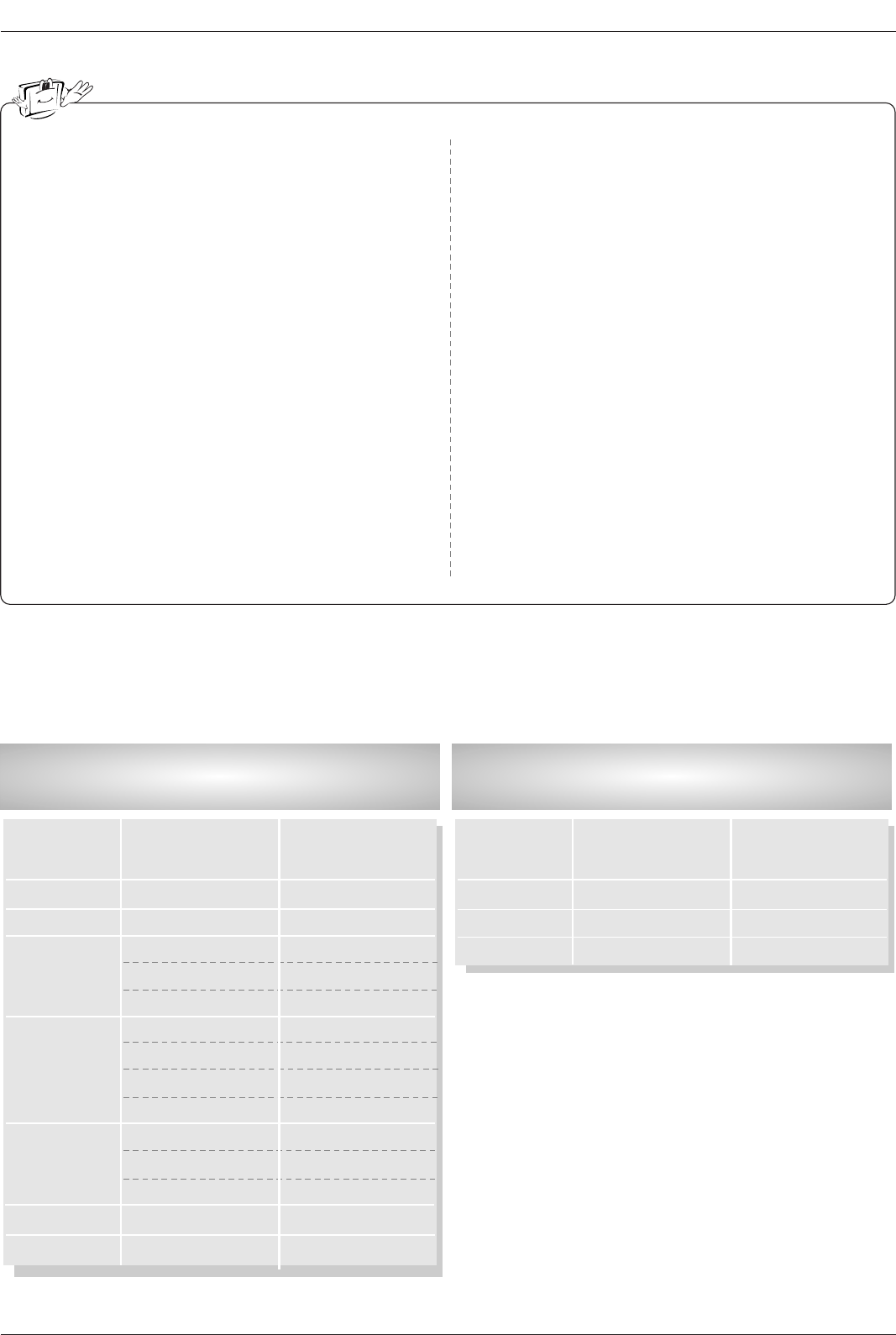
1. Here’s a great way to keep the dust off your screen for a while. Wet a soft cloth in a mixture of lukewarm water
and a little fabric softener or dish washing detergent. Wring the cloth until it’s almost dry, and then use it to wipe
the screen.
2. Make sure the excess water is off the screen, and then let it air-dry before you turn on your TV.
To remove dirt or dust, wipe the cabinet with a soft, dry, lint-free cloth.
Please be sure not to use a wet cloth.
If you expect to leave your TV dormant for a long time (such as a vacation), it’s a good idea to
unplug the power cord to protect against possible damage from lightning or power surges.
- Early malfunctions can be prevented. Careful and regular cleaning can extend the amount of time you will have
your new TV. Be sure to turn the power off and unplug the power cord before you begin any cleaning.
Cleaning the Screen
Cleaning the Screen
Cleaning the Cabinet
Cleaning the Cabinet
Extended
Extended Absence
Absence
Maintenance
Maintenance
Product Specifications
Product Specifications
•The specifications shown above may be changed without prior notice for quality improvement.
MODEL
Width (inches / mm)
Height (inches / mm)
Depth (inches / mm)
Weight (pounds / kg)
Power requirement
Television System
Program Coverage
External Antenna Impedance
55.9 / 1420
3520 / 889
14 / 356.8
137.8 / 62.5
36.3 / 922
23.6 / 599.7
8.6 / 218.5
54 / 24.5
50PC1DR-UA/50PC1DRA-UA 42LB1DR/42LB1DRA
NTSC-M, ATSC,64 & 256 QAM
VHF 2 ~ 13, UHF 14 ~ 69, CATV 1 ~ 135, CADTV 1 ~ 135, DTV 2 ~ 69
75 Ω
AC 100-240V~ 50/60Hz AC 100-240V~ 50/60Hz 2.0A

118