LG Electronics USA 50PY2DRUA PDP Display User Manual 528Aen TU 50PY22 1
LG Electronics USA PDP Display 528Aen TU 50PY22 1
Contents
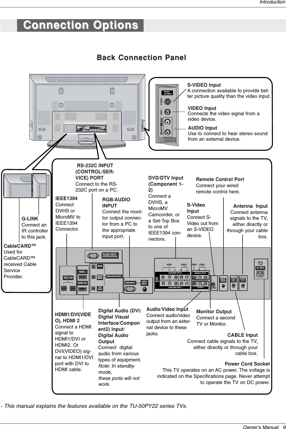
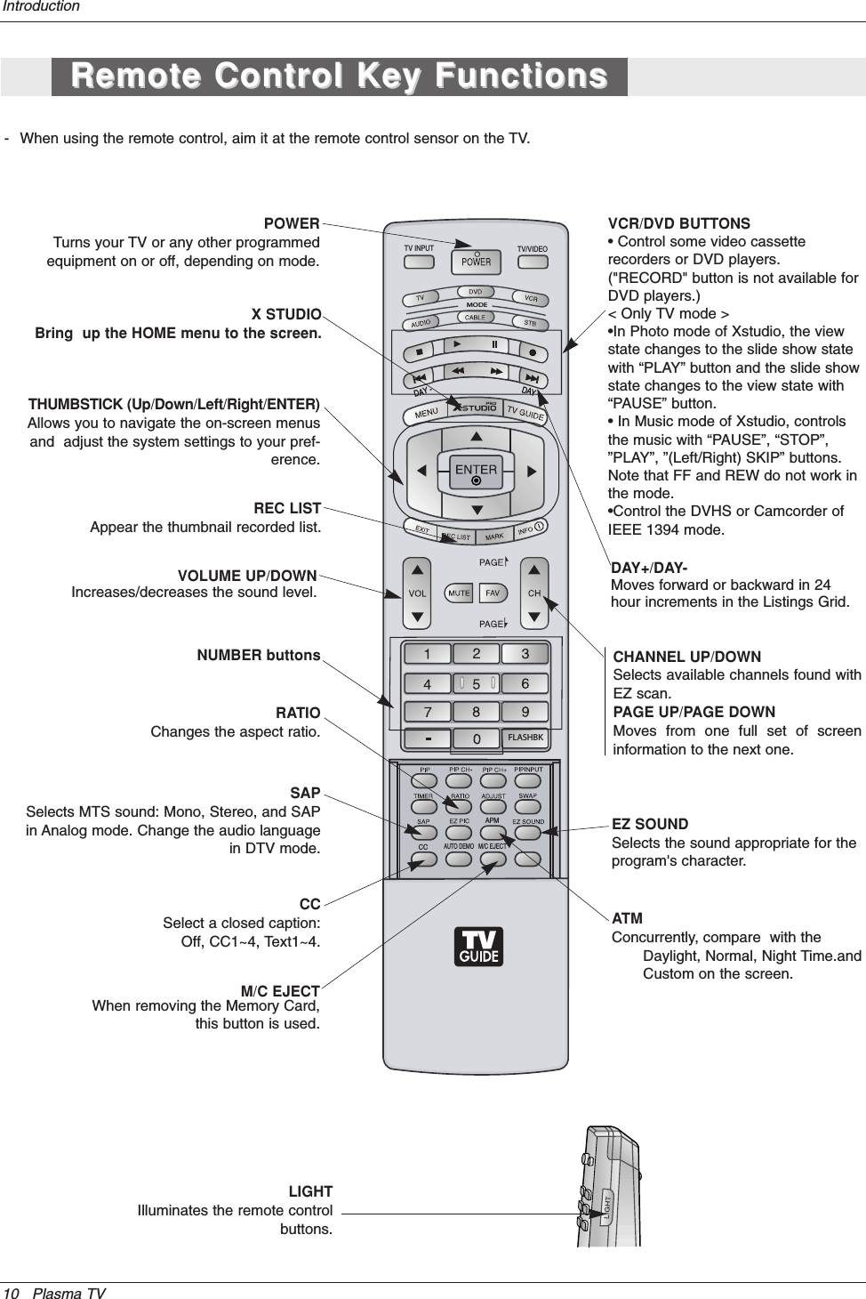
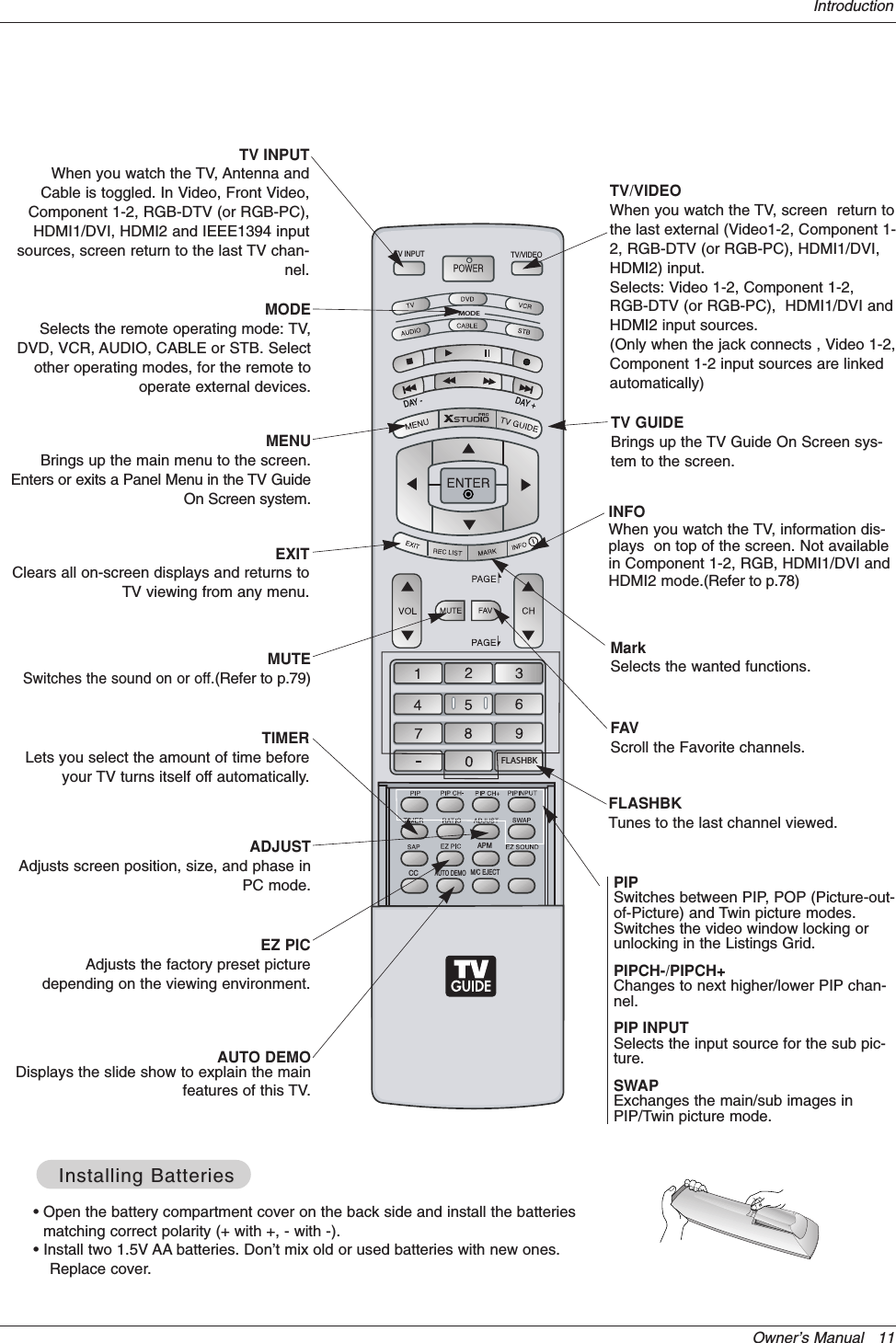
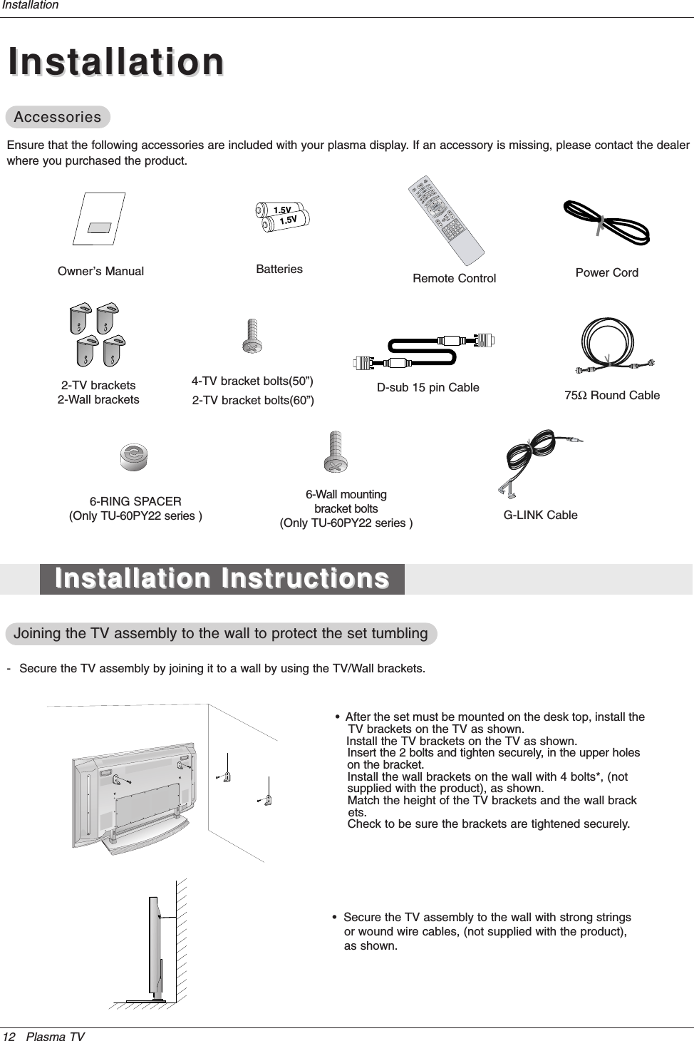
- 1. Users Manual Part 1 Revision 2
- 2. Users Manual Part 2 Revision 2
- 3. Users Manual Part 3 Revision 2
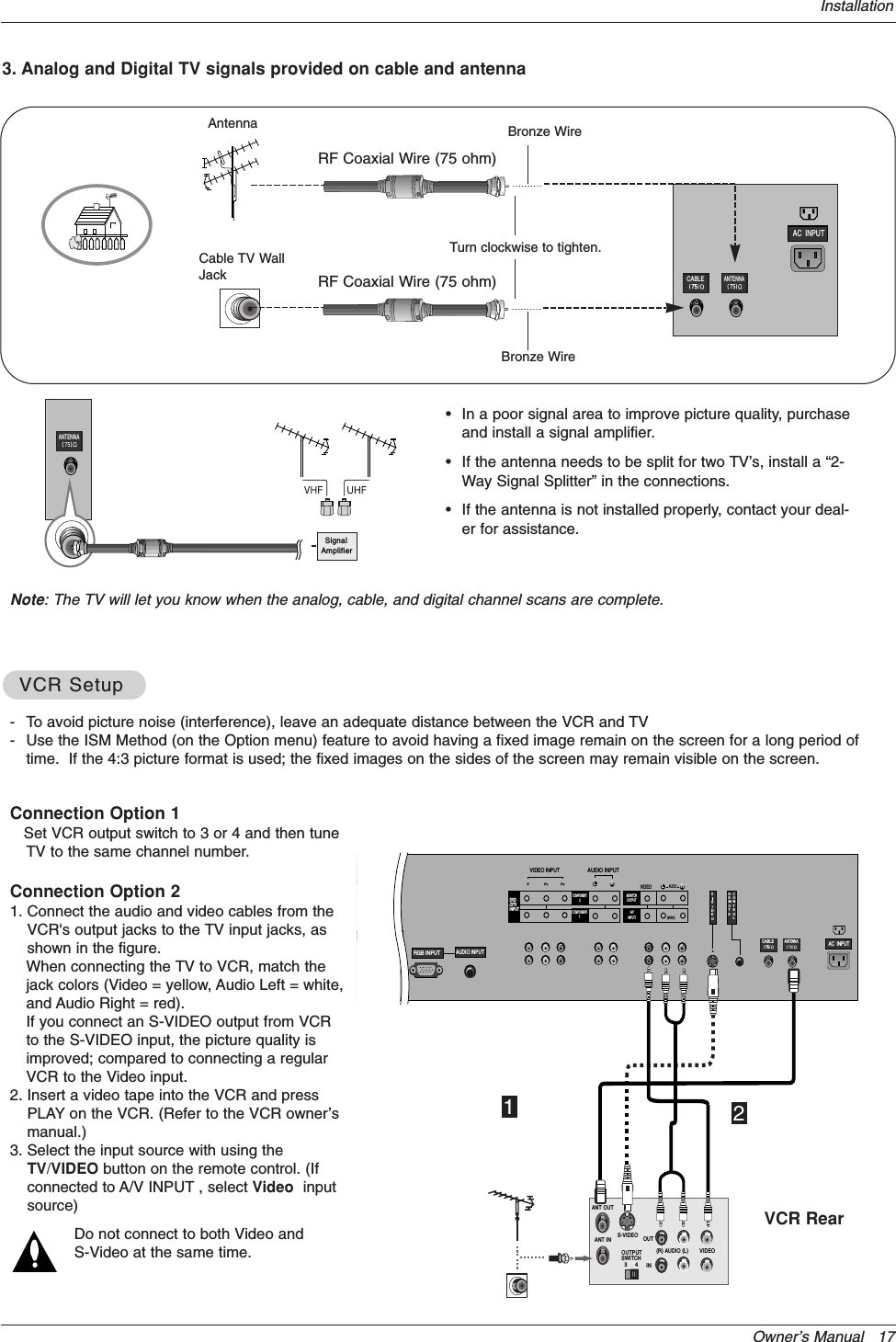
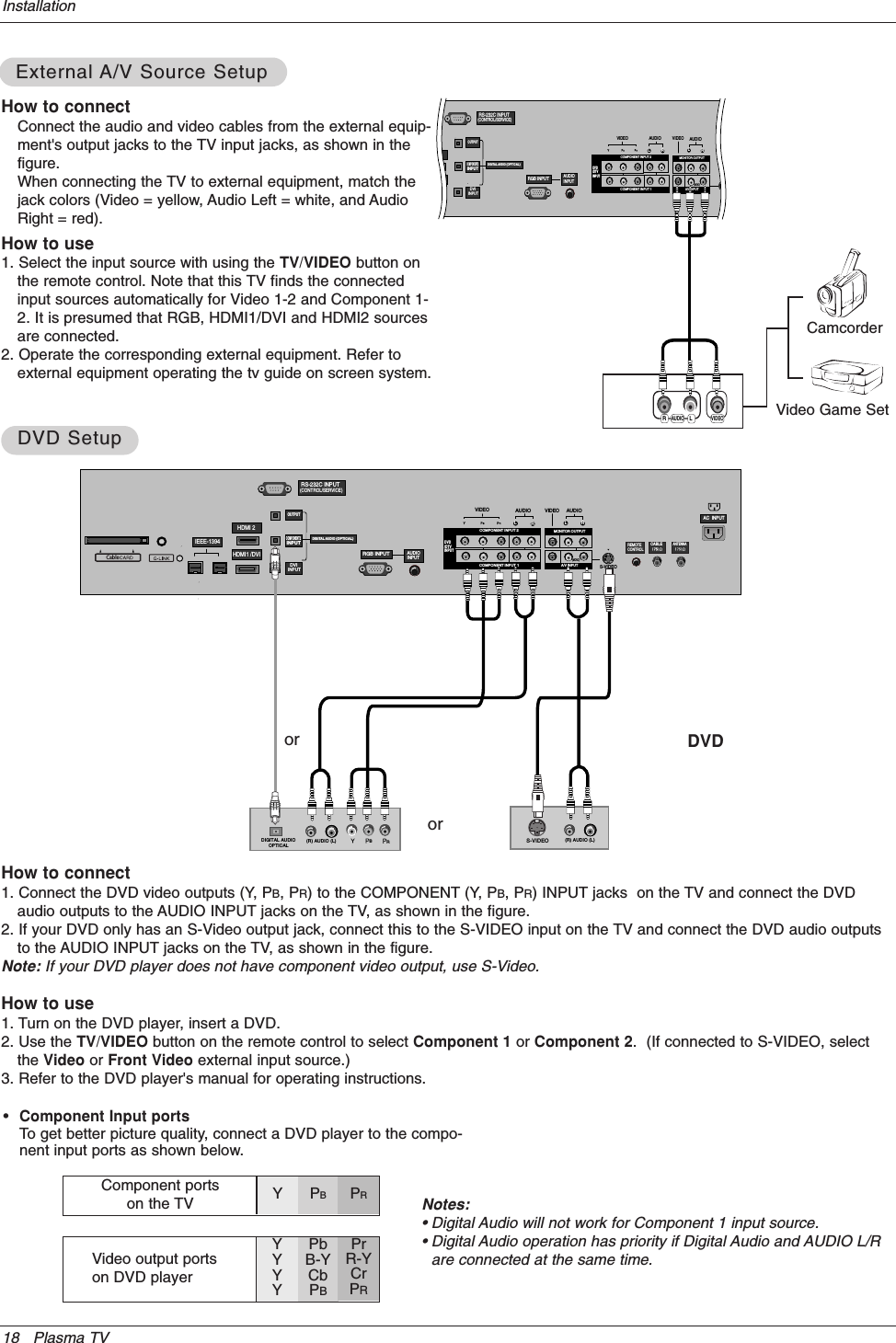
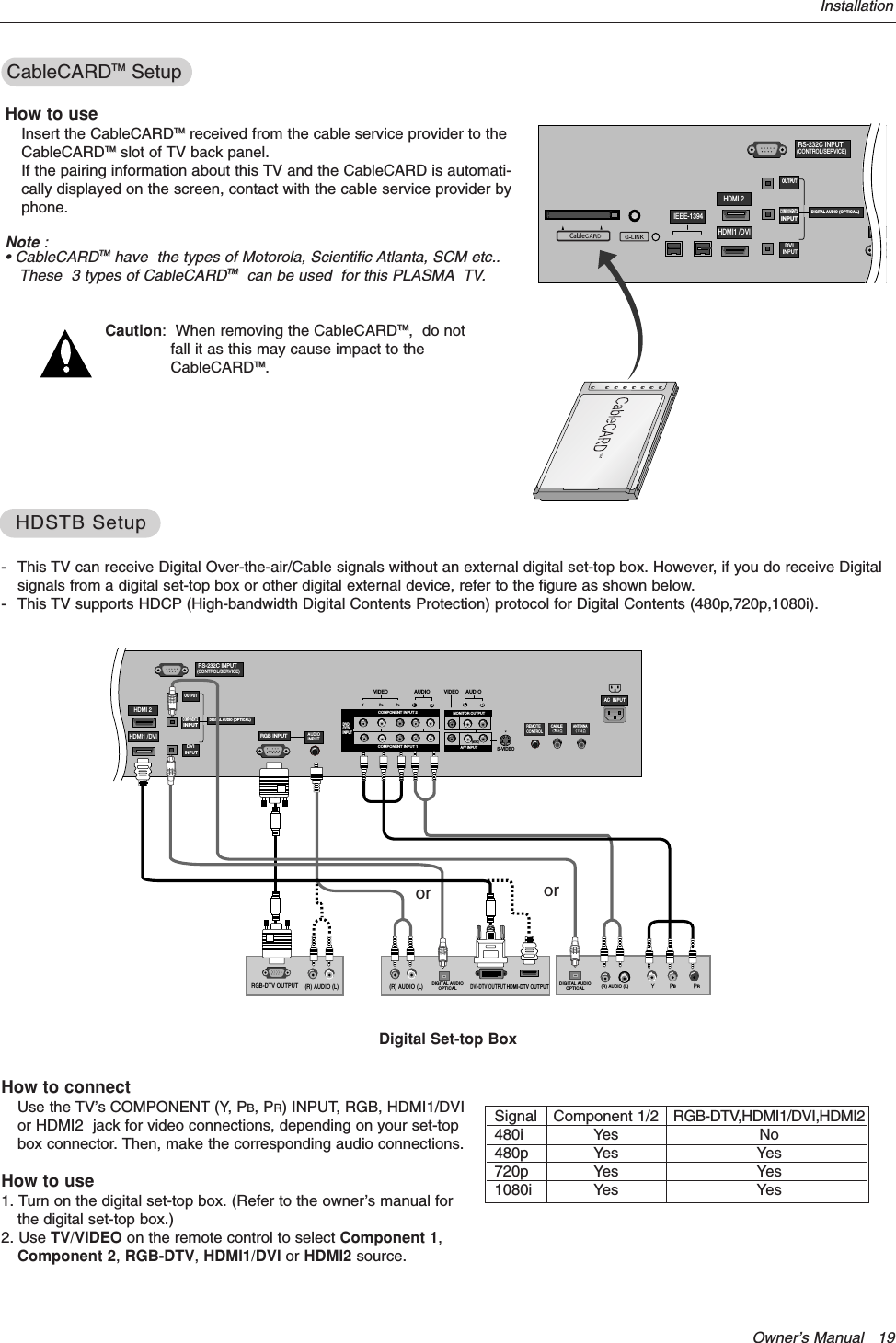
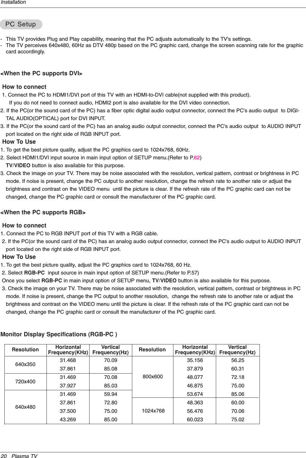
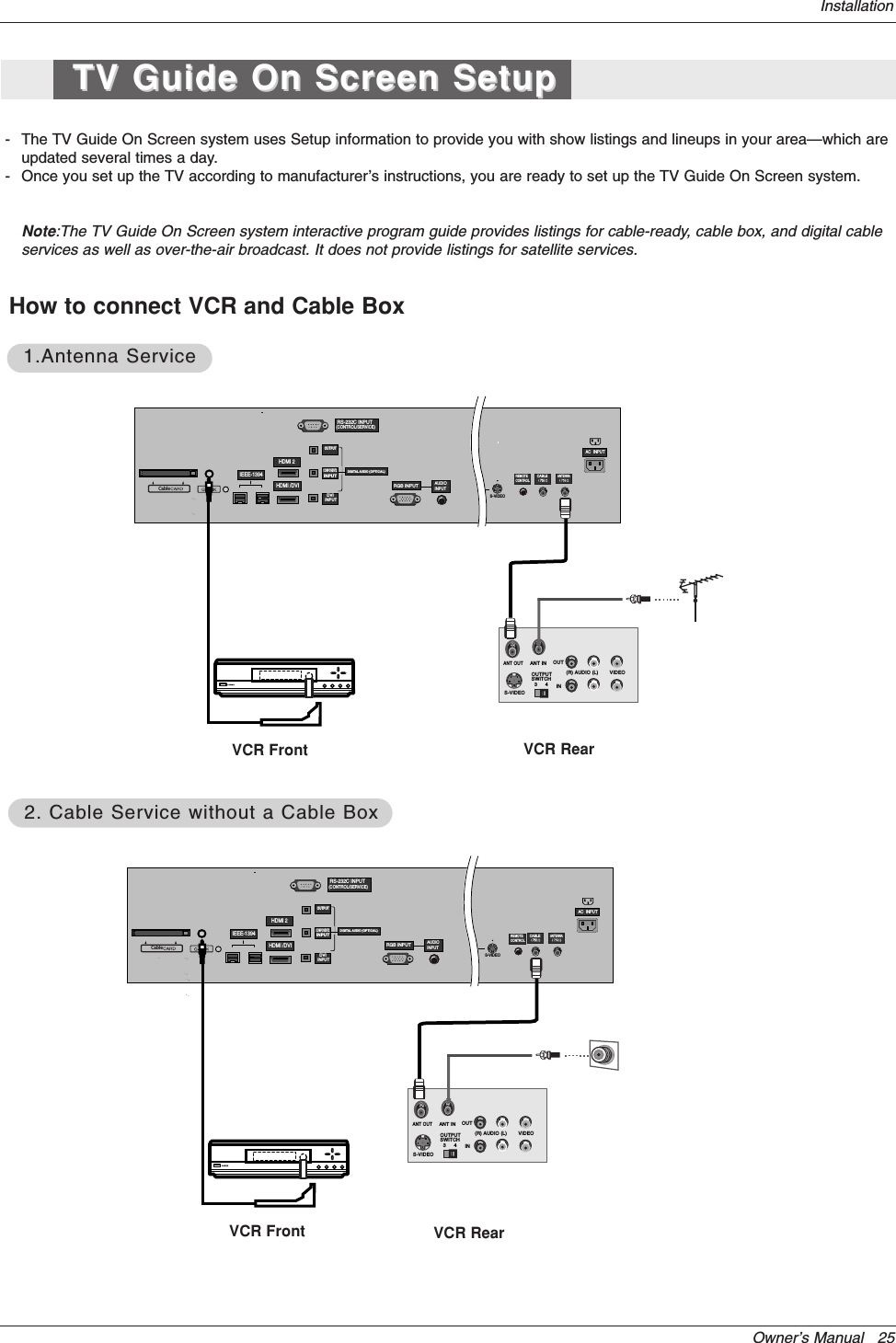
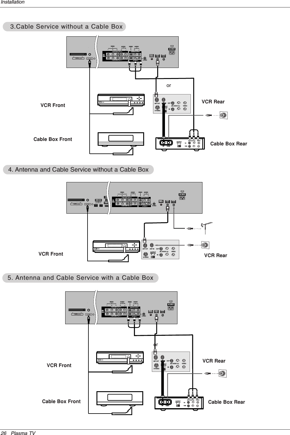
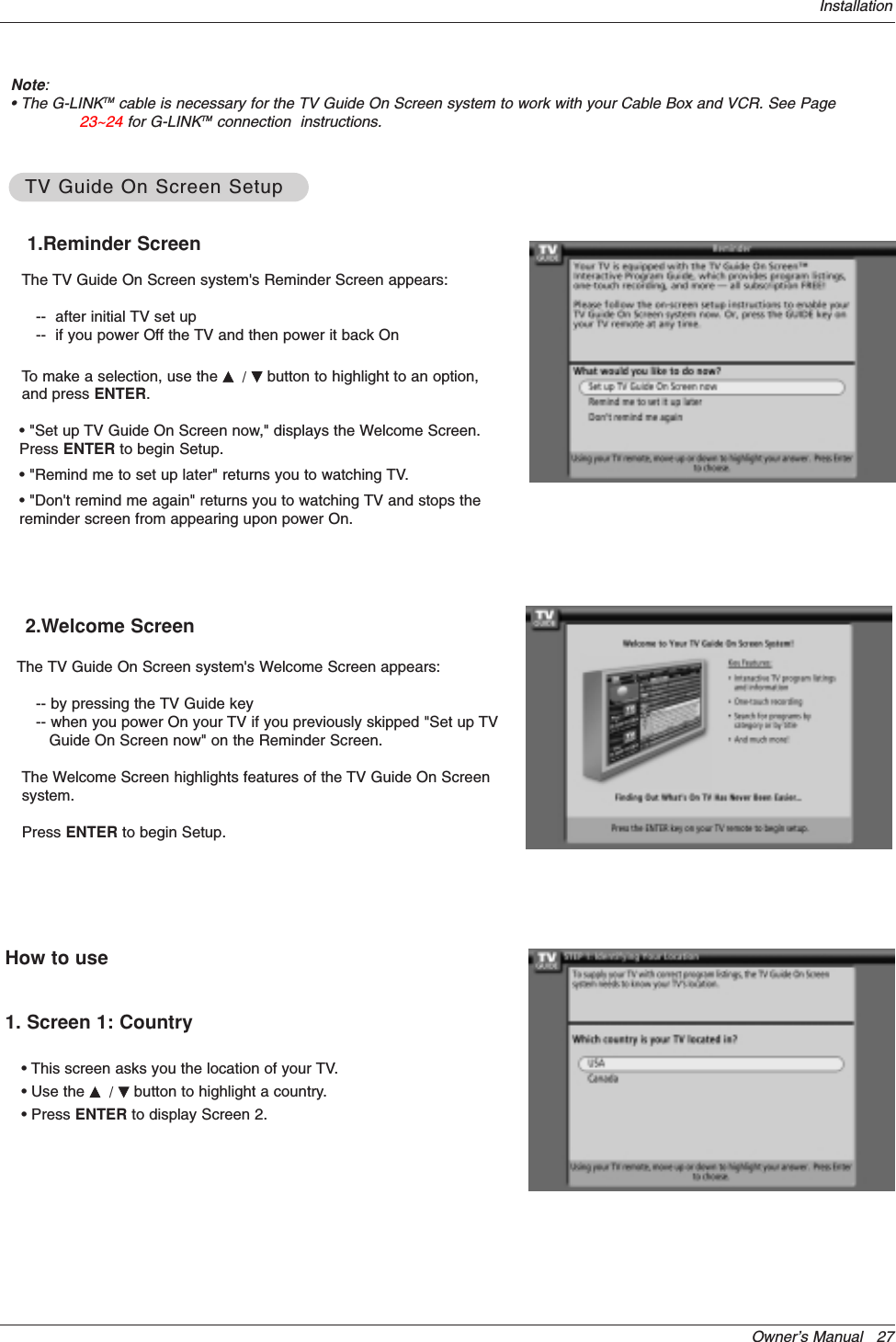
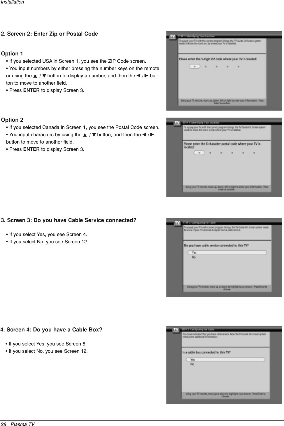
Users Manual Part 1 Revision 2