LG Electronics USA 60PK750UA PLASMA TV/MONITOR User Manual BBTV edit1 indd
LG Electronics USA PLASMA TV/MONITOR BBTV edit1 indd
Contents
- 1. User Manual 1
- 2. User Manual 2
- 3. User Manual 3
- 4. User Manual 4
User Manual 2
9
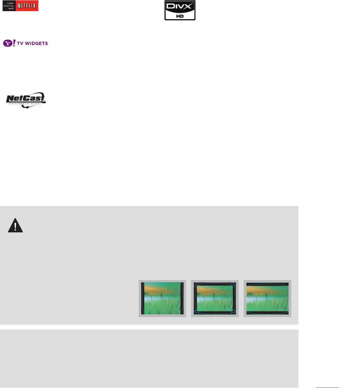
IMPORTANT INFORMATION TO PREVENT “IMAGE
BURN / BURN-IN” ON YOUR TV SCREEN
ABOUT DIVX VIDEO: DivX® is a
digital video format created by
DivX,Inc. This is an official DivX
Certified device that plays DivX
video. Visit www.divx.com for more
information and software tools to
convert your files into DivX video.
ABOUT DIVX VIDEO-ON-
DEMAND: This DivX Certified®
device must be registered in order
to play DivX Video-on-Demand
(VOD) content. To generate the
registration code, locate the DivX
VOD section in the device setup
menu. Go to vod.divx.com with this
code to complete the registration
process and learn more about
DivX VOD.
“DivX Certified to play DivX video
up to HD 1080p, including premi-
um content”
“Pat. 7,295,673;
7,460,688;7,519,274”
When a fixed image (e.g. logos, screen menus, video game, and computer display) is displayed
on the TV for an extended period, it can become permanently imprinted on the screen. This
phenomenon is known as “image burn” or “burn-in.” Image burn is not covered under the man-
ufacturer’s warranty.
In order to prevent image burn, avoid displaying a fixed image on your TV screen for a prolonged
period (2 or more hours for LCD, 1 or more
hours for Plasma).
Image burn can also occur on the letter-
boxed areas of your TV if you use the 4:3
aspect ratio setting for an extended period.
Unlimited instant access to movies
and TV shows with Netflix subscrip-
tion.
Yahoo! TV Widgets give you the
best of the Internet in perfect har-
mony with the simplicity and reli-
ability of your TV. TV Widgets deliv-
er a Cinematic InternetTM experi-
ence by converting your favorite
web services for viewing on the TV.
Stream movies, TV shows and
video, and get up to the minute
news, stock information and weath-
er updates directly to your TV using
Yahoo!, Netflix, YouTube and Vudu.
ON DISPOSAL
(Only Hg lamp used LCD TV)
The fluorescent lamp used in this product contains a small amount of mercury. Do not dispose of this
product with general household waste. Disposal of this product must be carried out in accordance to
the regulations of your local authority.
PREPARATION
PREPARATION
10
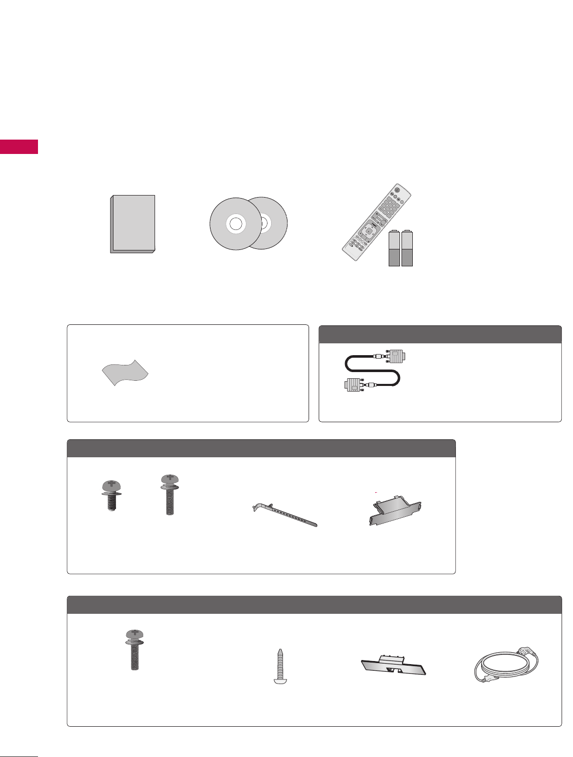
ACCESSORIES
PREPARATION
Ensure that the following accessories are included with your TV. If an accessory is missing, please con-
tact the dealer where you purchased the TV.
The accessories included may differ from the images below.
Option Extras
* Wipe spots on the exterior only
with the polishing cloth.
* Do not wipe roughly when remov-
ing stain. Excessive pressure may
cause scratch or discoloration.
Polishing Cloth
Not included with all models
1.5V 1.5V
1,5Vcc 1,5Vcc
D-sub 15 pin Cable
When using the VGA (D-sub 15
pin cable) PC connection, the
user must use shielded signal
interface cables with ferrite cores
to maintain standards compli-
ance.
LCD TV (32/42/46/52/60LD550, 47/55LD650)
Protection Cover
(Refer to P.17)
Power Cord
1.5V 1.5V
1,5Vcc 1,5Vcc
1.5V 1.5V
1,5Vcc 1,5Vcc
1.5V 1.5V
1,5Vcc 1,5Vcc
ENERGY
CHVOL
1 2
ABC
3
DEF
4
GHI
5
JKL
6
MNO
7
PQRS
8
TUV
0
9
WXYZ
P
A
G
E
SAVING
TV
AV MODE
INPUT
FAV
RATIO
MUTE
BACK EXIT
WIDGETS
ENTER
MARK
DELETE
CHAR/NUM
LIST
FLASHBK
MENU
FREEZE
Q.MENU
INFO
Owner’s Manual CD Manual,
Program CD
Remote Control,
Batteries (AAA)
Plasma TV
(M4 x 20)
Screws for stand assembly
(Refer to P.16)
Screw for stand fixing
(Refer to P.22)
x 8
(For 50PK750)
(For 32/42LD550)
Protection Cover
(Refer to p.15)
Cable Holder
(Refer to p.19)
x 2
x 3 x 4
Screws for stand assembly
(Refer to P.14)
(M5 x 14) (M4 x 28)

19
PREPARATION
1 LAN
Network connection for Netflix, Yahoo! TV Widgets,
etc.
Also used for photo and music files on local
network.
2 HDMI/DVI IN, HDMI IN
Digital Connection.
Supports HD video and Digital audio. Doesn’t
support 480i.
Accepts DVI video using an adapter or HDMI
to DVI cable (not included).
3 RGB IN (PC)
Analog PC Connection. Uses a D-sub 15 pin
cable (VGA cable).
AUDIO IN (RGB/DVI)
1/8” (0.32 cm) headphone jack for analog PC
audio input.
4 RS-232C IN (CONTROL & SERVICE) PORT
Used by third party devices.
This port is used for service or Hotel mode.
5 OPTICAL DIGITAL AUDIO OUT
Digital optical audio output for use with amps
and home theater systems.
Note: In standby mode, this port doesn’t work.
6 AV (Audio/Video) IN
Analog composite connection. Supports stan-
dard definition video only (480i).
7 ANTENNA/CABLE IN
Connect over-the air signals to this jack.
Connect cable signals to this jack.
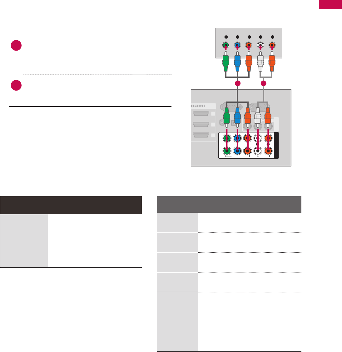
8 COMPONENT IN
Analog Connection.
Supports HD.
Uses a red, green, and blue cable for video &
red and white for audio.
9 WIRELESS CONTROL
Connect the Wireless Dongle to the TV to
control the external input devices connected
to Media Box wirelessly.
10 USB INPUT
Used for viewing photos and listening to
MP3s.
11 HEADPHONE INPUT
Plug the headphone into the headphone
socket.
12 Power Cord Socket
For operation with AC power.
Caution: Never attempt to operate the TV on
DC power.
13 REMOTE CONTROL IN PORT
For a wired remote control.
35
EXTERNAL EQUIPMENT SETUP
HD RECEIVER SETUP
To prevent the equipment damage, never plug in any power cords until you have finished connecting all
equipment.
I
mage shown may differ from your TV.
Supported Resolutions Y, CB/PB, CR/PR
1. How to connect
1Connect the video outputs (Y, PB, PR) of the
digital set-top box to the COMPONENT IN
VIDEO 1 or 2 jacks on the TV. Match the jack
colors (Y = green, PB = blue, and PR = red).
2Connect the audio output of the digital set-top
box to the COMPONENT IN AUDIO 1 or 2 jacks
on the TV.
2. How to use
Turn on the digital set-top box.
(Refer to the owner’s manual for the digital set-top
box operation.)
Select the Component1 or Component2 input
source on the TV using the INPUT button on the
remote control.
Component Connection
This TV can receive digital over-the-air/digital cable signals without an external digital set-top box.
However, if you do receive digital signals from a digital set-top box or other digital external device.
Signal Component HDMI
480i Yes No
480p Yes Yes
720p Yes Yes
1080i Yes Yes
1080p Yes Yes
Resolution Horizontal
Frequency(KHz)Vertical
Frequency(KHz)
720x480i 15.73 59.94
15.73 60.00
720x480p 31.47 59.94
31.50 60.00
1280x720p 44.96 59.94
45.00 60.00
1920x1080i
33.72 59.94
33.75 60.00
1920x1080p
26.97 23.976
27.00 24.00
33.71 29.97
33.75 30.00
67.432 59.94
67.50 60.00
EXTERNAL EQUIPMENT SETUP
L R
DVI OUTPUT
AUDIO
HDMI OUTPUT
RGB IN (PC)
LAN
WIRELESS
CONTROL
(RGB/DVI)
RS-232C IN
(
CONTROL&SERVICE)
OPTICAL
DIGITAL
/DVI IN
2
3
1
VIDEO
AUDIO
L(MONO)
R
AV IN 1
AUDIO IN
AUDIO OUT
RGB IN (PC)
LAN
WIRELESS
CONTROL
(RGB/DVI)
RS-232C IN
(
CONTROL&SERVICE)
OPTICAL
DIGITAL
VIDEO
AUDIO
L(MONO)
R
VIDEO AUDIO
COMPONENT INAV IN 1
Y PBPRL R
AUDIO IN
AUDIO OUT
2
1
VIDEO AUDIO
COMPONENT IN
Y PBPRL R
2
1
Y L RPBPR
/DVI IN
2
3
1
RGB IN (PC)
LAN
WIRELESS
CONTROL
RS-232C IN
(
CONTROL&SERVICE)
OPTICAL
DIGITAL
VIDEO
AUDIO
L(MONO)
R
VIDEO AUDIO
COMPONENT INAV IN 1
Y PBPRL R
AUDIO OUT
2
1
/DVI IN
2
3
1
(RGB/DVI)
AUDIO IN
1 2
EXTERNAL EQUIPMENT SETUP
EXTERNAL EQUIPMENT SETUP
36
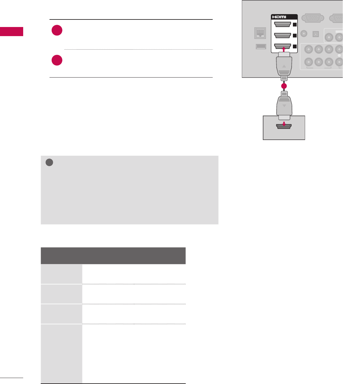
HDMI Connection
1. How to connect
1Connect the digital set-top box to HDMI/DVI IN
1, 2, 3, or 4 jack on the TV.
2No separate audio connection is necessary.
HDMI supports both audio and video.
2. How to use
Turn on the digital set-top box.
(Refer to the owner’s manual for the digital set-
top box.)
Select the HDMI1, HDMI2, HDMI3, or HDMI4 input
source on the TV using the INPUT
button on the
remote control.
!
?
!
?
NOTE
► Check HDMI cable over version 1.3.
If the HDMI cables don’t support HDMI version 1.3, it
can cause flickers or no screen display. In this case use
the latest cables that support HDMI version 1.3.
► HDMI Audio Supported Format: AC3 (32KHz,
44.1KHz,48KHz), Linear PCM (32KHz, 44.1KHz,48KHz)
HDMI-DTV
Resolution Horizontal
Frequency(KHz)Vertical
Frequency(KHz)
720x480p 31.47 59.94
31.50 60.00
1280x720p 44.96 59.94
45.00 60.00
1920x1080i
33.72 59.94
33.75 60.00
1920x1080p
26.97 23.976
27.00 24.00
33.71 29.97
33.75 30.00
67.432 59.94
67.50 60.00
L R
DVI OUTPUT
AUDIO
HDMI OUTPUT
RGB IN (PC)
LAN
WIRELESS
CONTROL
(RGB/DVI)
RS-232C IN
(
CONTROL&SERVICE)
OPTICAL
DIGITAL
/DVI IN
2
3
1
VIDEO
AUDIO
L(MONO)
R
AV IN 1
AUDIO IN
AUDIO OUT
RGB IN (PC)
LAN
WIRELESS
CONTROL
(RGB/DVI)
R
S-232C IN
(
CONTROL&SERVICE)
OPTICAL
DIGITAL
VIDEO
AUDIO
L(MONO
)
R
VIDEO
AUDIO
COMPONENT INAV IN 1
Y PBPRL
R
AUDIO IN
AUDIO OUT
2
1
VIDEO AUDIO
COMPONENT IN
Y PBPRL R
2
1
Y L RPBPR
/DVI IN
2
3
1
RGB IN (PC)
LAN
WIRELESS
CONTROL
RS-232C IN
(
CONTROL&SERVICE)
OPTICAL
DIGITAL
VIDEO
AUDIO
L(MONO)
R
VIDEO AUDIO
COMPONENT INAV IN 1
Y PBPRL R
AUDIO OUT
2
1
/DVI IN
2
3
1
(RGB/DVI)
AUDIO IN
1
47
EXTERNAL EQUIPMENT SETUP
Supported Display Specifications (RGB-PC, HDMI-PC)
!
?
!
?
NOTE
►To get the the best picture quality, adjust the PC graphics card to 1920x1080.
►Depending on the graphics card, DOS mode may not work if a HDMI to DVI Cable is in use.
►In PC mode, there may be noise associated with the resolution, vertical pattern, contrast or bright-
ness. If noise is present, change the PC output to another resolution, change the refresh rate to
another rate or adjust the brightness and contrast on the PICTURE menu until the picture is clear.
►Avoid keeping a fixed image on the screen for a long period of time. The fixed image may become
permanently imprinted on the screen.
►The synchronization input form for Horizontal and Vertical frequencies is separate.
►Depending on the graphics card, some resolution settings may not allow the image to be posi-
tioned on the screen properly.
►If there are overscan in HDMI-PC 1920x1080, change aspect ratio to Just scan.
►When selecting HDMI-PC, set the “Input Label - PC” in the OPTION menu.
Resolution Horizontal
Frequency(KHz)Vertical
Frequency(KHz)
640x350 31.468 70.09
720x400 31.469 70.08
640x480 31.469 59.94
800x600 37.879 60.31
1024x768 48.363 60.00
1280x768 47.776 59.87
1360x768
47.712 60.015
1280x1024
63.981 60.02
1600x1200
75.00 60.00
1920x1080
RGB-PC
66.587 59.934
1920x1080
HDMI-PC
67.50 60.00
EXTERNAL EQUIPMENT SETUP
EXTERNAL EQUIPMENT SETUP
52
RGB IN (PC)
WIRELESS
CONTROL
(RGB/DVI)
RS-232C IN
(
CONTROL&SERVICE)
OPTICAL
DIGITAL
/DVI IN
2
3
1
VIDEO
AUDIO
L(MONO)
R
VIDEO AUDIO
COMPONENT INAV IN 1
Y PBPRL R
AUDIO IN
AUDIO OUT
2
1
LAN
Broadband modem
Broadband modem
Router
Broadband Service
Broadband Service
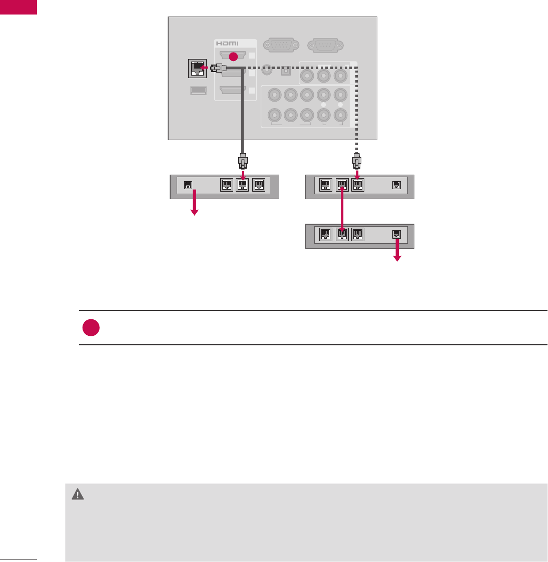
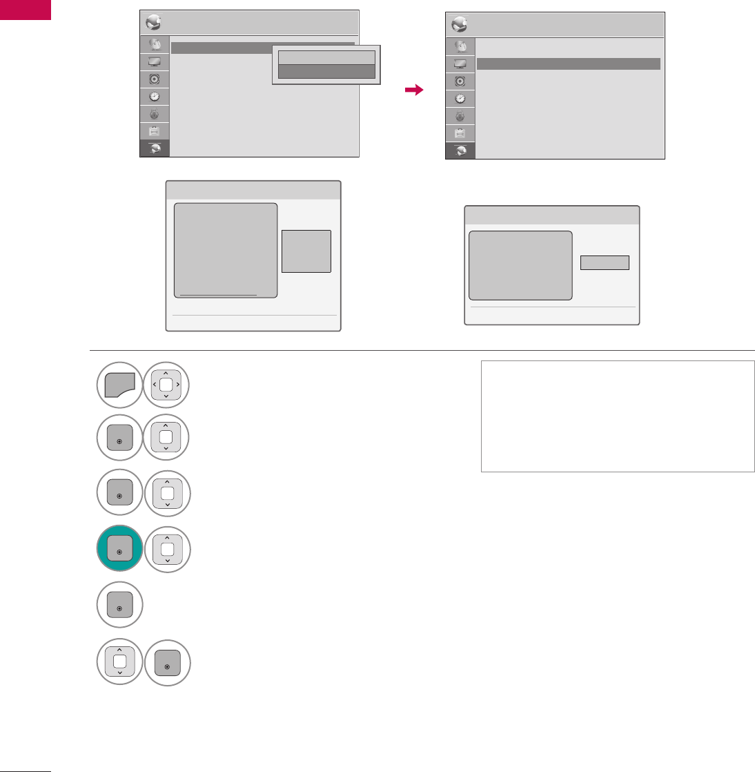
NETWORK SETUP
This TV can be connected to a local area network (LAN) via the LAN port. After making the physical
connection, the TV needs to be set up for network communication.
!
?
!
?
CAUTION
► Do not connect a modular phone cable to the LAN port.
► Since there are various connection methods, please follow the specifications of your telecommu-
nication carrier or internet service provider.
1. How to connect
1Connect the LAN port of the Modem or Router to the LAN port on the TV.
2. How to use
Select “Network Setting - IP Auto Setting” in the NETWORK menu (►p.?).
After connecting the LAN port, use the NetCast menu (Yahoo! TV Widgets, Netflix, Vudu,
YouTube, My Media etc.) (►p.70-127).
Wired Network Connection
1
53
EXTERNAL EQUIPMENT SETUP
IN 4
AV IN 2
VIDE
O
AUDIO
L(MONO)
R
H/P USB IN 1 USB IN 2
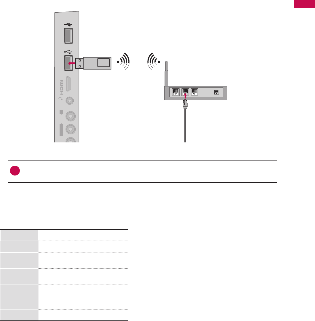
This connection is to use an Access Point or an wireless router.
The network configuration and connection method may vary depending on the equipment in use and
the network environment. Refer to the setup instructions supplied with your access point or wireless
router for detailed connection steps and network settings.
1. How to connect
1Connect the “LG Wi-Fi Dongle (AN-WF100) (sold separately)” to the USB IN 1 or 2 port on
the TV.
2. How to use
Select “Network Setting - IP Auto Setting” in the NETWORK menu (►p.?).
Wireless Network Connection
Standard IEEE 802.11a/b/g/n
Host interface USB 2.0
Frequency
Range
2.412GHz ~ 2.4835GHz
5.15 GHz ~ 5.850 GHz
Security 64/128bit WEP, WPA,
TKIP, AES, WPS (PIN, PBC)
Data rate
802.11a/g: 54Mbps
802.11b: 11Mbps
802.11n: 300Mbps(40MHz)
Throughput 110Mbps @ 300Mbps
Wi-Fi Dongle (AN-WF100) SPEC

EXTERNAL EQUIPMENT SETUP
EXTERNAL EQUIPMENT SETUP
54
!
?
!
?
NOTE
► Use a standard LAN cable with this TV. Cat5
or better with a RJ45 connector.
► Many network connection problems during
set up can often be fixed by re-setting the
router or modem. After connecting the player
to the home network, quickly power off and/
or disconnect the power cable of the home
network router or cable modem. Then power
on and/or connect the power cable again.
► Depending on the internet service provider
(ISP), the number of devices that can receive
internet service may be limited by the appli-
cable terms of service. For details, contact
your ISP.
► LG is not responsible for any malfunction of
the TV and/or the internet connection feature
due to communication errors/malfunctions
associated with your broadband internet con-
nection, or other connected equipment.
► LG is not responsible for problems with in your
internet connection.
► Some content available through the network
connection may not be compatible with the
TV. If you have questions about such content,
please contact the producer of the content.
► You may experience undesired results if the
network connection speed does not meet the
requirements of the content being accessed.
► Some internet connection operations may not
be possible due to certain restrictions set by
the Internet service provider (ISP) supplying
your broadband Internet connection.
► Any fees charged by an ISP including, without
limitation, connection charges are your respon-
sibility.
► A 10 Base-T or 100 Base-TX LAN port is
required for connection to this TV. If your inter-
net service does not allow for such a connec-
tion, you will not be able to connect the TV.
► A DSL modem is required to use DSL service
and a cable modem is required to use cable
modem service. Depending on the access
method of and subscriber agreement with
your ISP, you may not be able to use the inter-
net connection feature contained in this TV or
you may be limited to the number of devices
you can connect at the same time. (If your ISP
limits sub-scription to one device, this TV may
not be allowed to connect when a PC is
already connected.)
► The use of a “Router” may not be allowed or
its usage may be limited depending on the
policies and restrictions of your ISP. For details,
contact your ISP directly.
► The wireless network operate at 2.4GHz radio
frequencies that are also used by other house-
hold devices such as cordless telephone,
Bluetooth® devices, microwave oven, and can
be affected by interference from them.
► Turn off all unused network equipment in your
local home network. Some devices may gen-
erate network traffic
► For the purpose of the better transmission,
placing the player from the access point as
close as possible.
► In some instances, placing the access point or
wireless router at least 1.5 ft (0.45m) above
the floor may improve the reception.
► Move closer to the access point if possible or
re-orient the player so there is nothing between
it and the access point.
► The reception quality over wireless depends
on many factors such as type of the access
point, distance between the player and access
point, and the location of the player.
55
EXTERNAL EQUIPMENT SETUP
Gateway
DTV
Gateway
DNS
Internet
DNS
DTV
Gateway Gateway
This feature requires an always-on
broadband internet connection.
You do not need to connect to a PC
to use this function.
If the Network Setting is not working,
check your network conditions. Check
the LAN cable and make sure your
router has DHCP turned on if you
wish to use the Auto Setting.
If the Network Setting is not com-
pleted, network may not operate nor-
mally.
IP Auto Setting: Select it if there is a
DHCP server on the local area net-
work (LAN) via wired connection, the
TV will automatically be allocated an
IP address. If you’re using a broad-
band router or broadband modem
that has a DHCP (Dynamic Host
Configuration Protocol) server func-
tion. The IP address will automati-
cally be determined.
IP Manual Setting: Select it if there is
no DHCP server on the network and
you want to set the IP address manu-
ally.
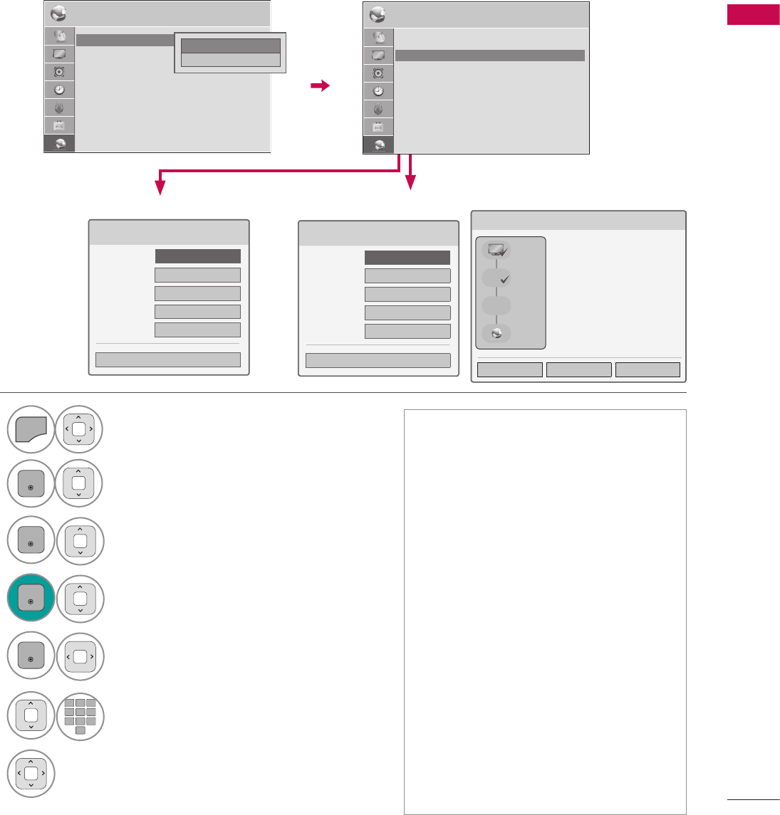
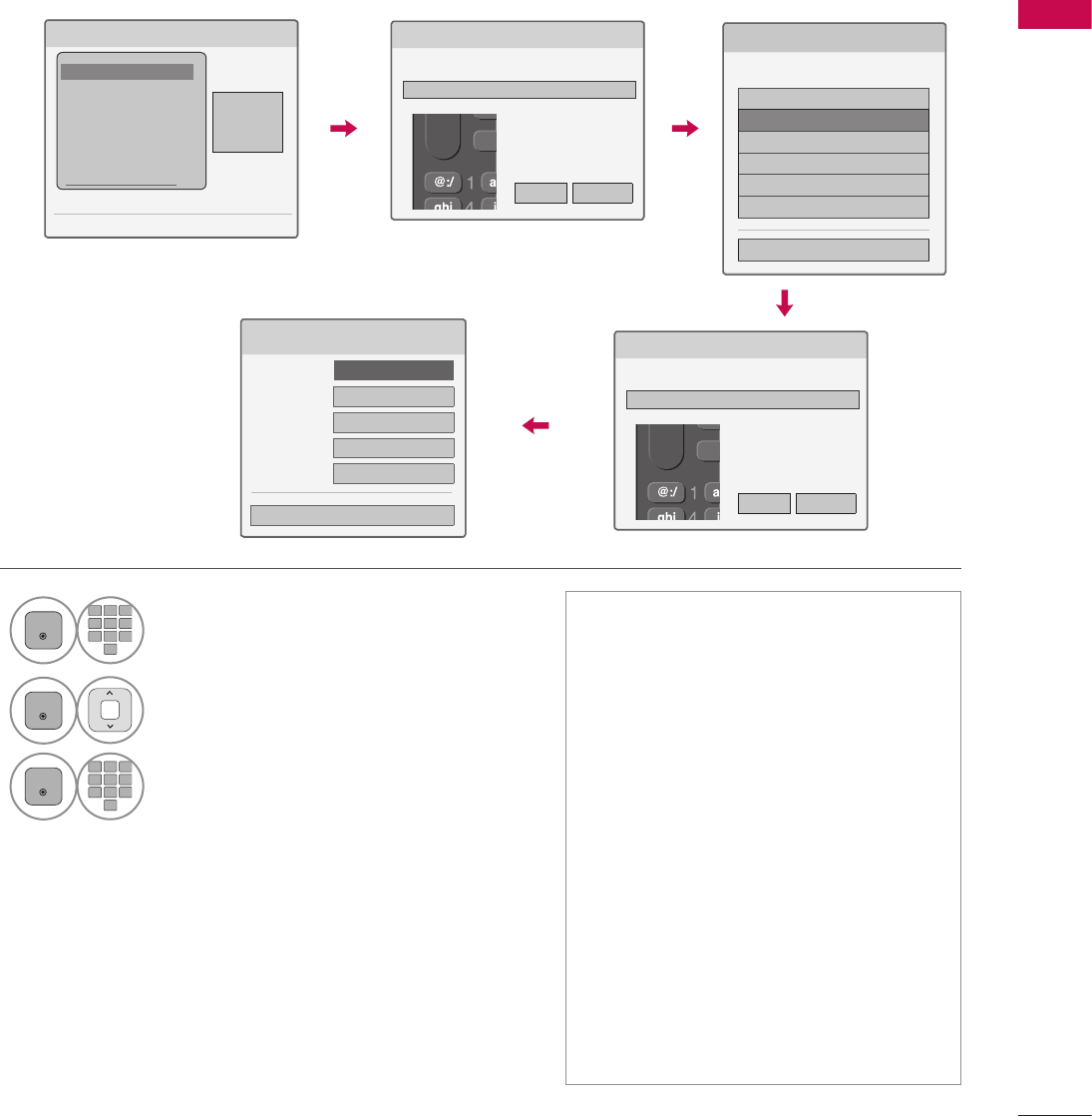
Wired Network Setup
1
MENU
Select NETWORK.
2
ENTER
Select Network Type.
3
ENTER
Select Wired.
4
ENTER
Select Network Setting.
5
ENTER
Select IP Auto Setting or IP
Manual Setting.
6
1 2
ABC
3
DEF
4
GHI
5
JKL
6
MNO
7
PQRS
8
TUV
0
9
WXYZ
When Selecting IP Manual
Setting:
Input the internet protocol.
7Select a desired menu option
(Setting, Test, Close).
IP Auto Setting
IP Manual Setting
If wired and wireless networks are both available, use Wired. Because the connected devices connect
directly to the network and are not subject to radio frequency interference.
After making the physical connection, a small number of home networks may require the TV network
setting to be adjusted.
For detail information, contact your internet provider or router manual.
EXTERNAL EQUIPMENT SETUP
EXTERNAL EQUIPMENT SETUP
56
Setting up the AP (Access Point) or the wireless router is required before connecting the TV to the
network.
Wireless Network Setup
Setting: Return to the IP setting
menu.
Test: Test the current network status
after setting the network.
Close: Return to the previous menu.
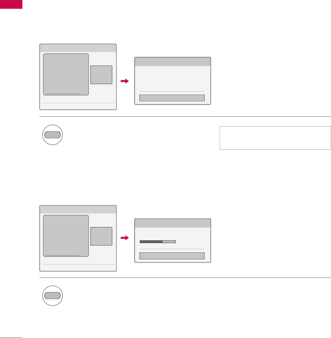
1
MENU
Select NETWORK.
2
ENTER
Select Network Type.
3
ENTER
Select Wireless.
4
ENTER
Select Network Setting.
5
ENTER
Scan the all available AP (Access
Point) or wireless routers within
range and display them as a list.
6
ENTER
Select an AP (Access Point)
or wireless router on the list.
57
EXTERNAL EQUIPMENT SETUP
DELETE
SYMB
CHAR/NUM
DELETE
SYMB
CHAR/NUM
WPA1
WPA2
7
ENTER
1 2
ABC
3
DEF
4
GHI
5
JKL
6
MNO
7
PQRS
8
TUV
0
9
WXYZ
When selecting Direct Input,
Input the SSID (Service Set
Identifier).
8
ENTER
Select the wireless network
security.
9
ENTER
1 2
ABC
3
DEF
4
GHI
5
JKL
6
MNO
7
PQRS
8
TUV
0
9
WXYZ
Input the password.
Reteat steo 5-7 on P.?
If you have security on your AP
(Access Point) or wireless router, ver-
ify that the WEP (Wired Equivalent
Privacy) or WPA (Wi-Fi Protected
Access) key that was entered into the
TV matches the router’s information
exactly. You need to input the secu-
rity code as necessary.
WEP security mode generally have 4
keys available on an access point or
wireless router’s setting. If your
access point or wireless router use
WEP security, enter the security code
of the key “No.1” to connect on your
home network.
An Access Point is a device that
allows you to connect to your home
network wirelessly.
Direct Input Connection: When a security code is not set
EXTERNAL EQUIPMENT SETUP
EXTERNAL EQUIPMENT SETUP
58
If your access point or wireless router that supports WPS, it’s available to use your access point or
wireless router within 120 counts. You do not need to know the access point name (SSID: Service Set
Identifier) and security code of your access point or wireless router.
WPS (Wi-Fi Protected Setup) Connection: When a security code is
already set)
PIN (Personal Identification Number)
PBC (Push Button Configuration)
7Connect the acccess point
as PIN.
Reteat steo 5-7 on P.?
7Connect the acccess point
as PBC.
GREEN
BLUE
PIN Number 는 Dongle 이 가지고
있는 고유의 8자리 숫자임