LG Electronics USA 60PK950UA Plasma TV and Monitor User Manual
LG Electronics USA Plasma TV and Monitor
Contents
- 1. User manual 1 of 2
- 2. User manual 2 of 2
User manual 1 of 2

P/NO : SAC34134203 (1001-REV03) www.lge.com
OWNER’S MANUAL
LED LCD TV / LCD TV
PLASMA TV
Please read this manual carefully before operating
your set and retain it for future reference.
2
WARNING / CAUTION
The lightning flash with arrowhead
symbol, within an equilateral trian-
gle, is intended to alert the user to
the presence of uninsulated “dan-
gerous voltage” within the product’s enclo-
sure that may be of sufficient magnitude to
constitute a risk of electric shock to persons.
The exclamation point within an equi-
lateral triangle is intended to alert
the user to the presence of important oper-
ating and maintenance (servicing) instruc-
tions in the literature accompanying the
appliance.
TO REDUCE THE RISK OF ELECTRIC
SHOCK DO NOT REMOVE COVER (OR
BACK). NO USER SERVICEABLE PARTS
INSIDE. REFER TO QUALIFIED SERVICE
PERSONNEL.
WARNING/CAUTION
TO REDUCE THE RISK OF FIRE AND
ELECTRIC SHOCK, DO NOT EXPOSE THIS
PRODUCT TO RAIN OR MOISTURE.
NOTE TO CABLE/TV INSTALLER
This reminder is provided to call the CATV system
installer’s attention to Article 820-40 of the National
Electric Code (U.S.A.). The code provides guide-
lines for proper grounding and, in particular, speci-
fies that the cable ground shall be connected to the
grounding system of the building, as close to the
point of the cable entry as practical.
WARNING / CAUTION
To prevent fire or shock hazards, do not expose
this product to rain or moisture.
FCC Notice
Class B digital device
This equipment has been tested and found to
comply with the limits for a Class B digital device,
pursuant to Part 15 of the FCC Rules. These
limits are designed to provide reasonable pro-
tection against harmful interference in a residen-
tial installation. This equipment generates, uses
and can radiate radio frequency energy and, if not
installed and used in accordance with the
instructions, may cause harmful interference to
radio communications. However, there is no
guarantee that interference will not occur in a
particular installation. If this equipment does
cause harmful interference to radio or television
reception, which can be determined by turning
the equipment off and on, the user is encour-
aged to try to correct the interference by one or
more of the following measures:
- Reorient or relocate the receiving antenna.
- Increase the separation between the equip-
ment and receiver.
- Connect the equipment to an outlet on a circuit
different from that to which the receiver is con-
nected.
- Consult the dealer or an experienced radio/TV
technician for help.
This device complies with part 15 of the FCC
Rules.
Operation is subject to the following two condi-
tions: (1) This device may not cause (harmful)
interference, and (2) this device must accept
any interference received, including interference
that may cause undesired operation (of the
device).
Any changes or modifications in construction of
this device which are not expressly approved by
the party responsible for compliance could void
the user’s authority to operate the equipment.
CAUTION
Do not attempt to modify this product in any
way without written authorization from LG
Electronics.
Unauthorized modification could void the user’s
authority to operate this product.
3
SAFETY INSTRUCTIONS
Read these instructions.
Keep these instructions.
Heed all warnings.
Follow all instructions.
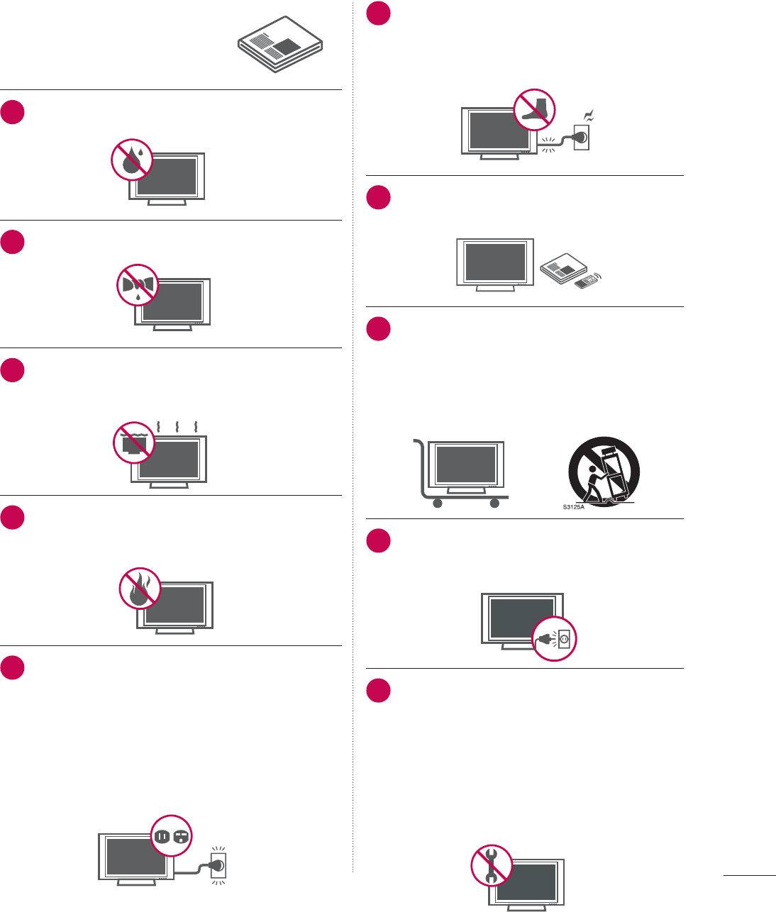
1Do not use this apparatus near water.
2Clean only with dry cloth.
3
Do not block any ventilation openings. Install in
accordance with the manufacturer’s instructions.
4
Do not install near any heat sources such as
radiators, heat registers, stoves, or other appa-
ratus (including amplifiers) that produce heat.
5
Do not defeat the safety purpose of the polarized
or grounding-type plug. A polarized plug has
two blades with one wider than the other. A
grounding type plug has two blades and a third
grounding prong, The wide blade or the third
prong are provided for your safety. If the provided
plug does not fit into your outlet, consult an elec-
trician for replacement of the obsolete outlet.
6Protect the power cord from being walked
on or pinched particularly at plugs, conve-
nience receptacles, and the point where
they exit from the apparatus.
7Only use attachments/accessories speci-
fied by the manufacturer.
8Use only with the cart, stand, tripod, bracket,
or table specified by the manufacturer, or
sold with the apparatus. When a cart is
used, use caution when moving the cart/
apparatus combination to avoid injury from
tip-over.
9Unplug this apparatus during lighting
storms or when unused for long periods
of time.
10
Refer all servicing to qualified service per-
sonnel. Servicing is required when the
apparatus has been damaged in any way,
such as power-supply cord or plug is dam-
aged, liquid has been spilled or objects
have fallen into the apparatus, the appara-
tus has been exposed to rain or moisture,
does not operate normally, or has been
dropped.
IMPORTANT SAFETY INSTRUCTIONS
4
SAFETY INSTRUCTIONS
11
Never touch this apparatus or antenna during
a thunder or lighting storm.
12
When mounting a TV on the wall, make sure
not to install the TV by the hanging power
and signal cables on the back of the TV.
13
Do not allow an impact shock or any objects
to fall into the product, and do not drop onto
the screen with something.
14
CAUTION concerning the Power Cord:
It is recommend that appliances be placed
upon a dedicated circuit; that is, a single
outlet circuit which powers only that appli-
ance and has no additional outlets or
branch circuits. Check the specification page
of this owner's manual to be certain.
Do not connect too many appliances to the
same AC power outlet as this could result in
fire or electric shock.
Do not overload wall outlets. Overloaded wall
outlets, loose or damaged wall outlets, exten-
sion cords, frayed power cords, or damaged
or cracked wire insulation are dangerous . Any
of these conditions could result in electric
shock or fire. Periodically examine the cord of
your appliance, and if its appearance indicates
damage or deterioration, unplug it, discon-
tinue use of the appliance, and have the cord
replaced with an exact replacement part by
an authorized servicer. Protect the power cord
from physical or mechanical abuse, such as
being twisted, kinked, pinched, closed in a
door, or walked upon. Pay particular attention
to plugs, wall outlets, and the point where the
cord exits the appliance.
Do not use a damaged or loose power cord.
Do not pull on the power cord to unplug the
TV. Grasp the plug when unplugging the
power cord.
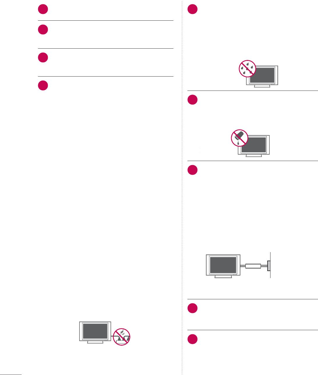
15
WARNING - To reduce the risk of fire or elec-
trical shock, do not expose this product to
rain, moisture or other liquids. Do not touch
the TV with wet hands. Do not install this
product near flammable objects such as
gasoline or candles or expose the TV to
direct air conditioning.
16
Do not expose to dripping or splashing and
do not place objects filled with liquids, such
as vases, cups, etc. on or over the appara-
tus (e.g. on shelves above the unit).
17
GROUNDING
Ensure that you connect the earth ground
wire to prevent possible electric shock (i.e. a
TV with a three-prong grounded AC plug
must be connected to a three-prong ground-
ed AC outlet). If grounding methods are not
possible, have a qualified electrician install a
separate circuit breaker.
Do not try to ground the unit by connecting it
to telephone wires, lightening rods, or gas
pipes.
Power
Supply
Short-circuit
Breaker
18
DISCONNECTING DEVICE FROM MAINS
Mains plug is the disconnecting device. The
plug must remain readily operable.
19
As long as this unit is connected to the AC
wall outlet, it is not disconnected from AC
power even if you turn off the power switch
on the unit.
5
20
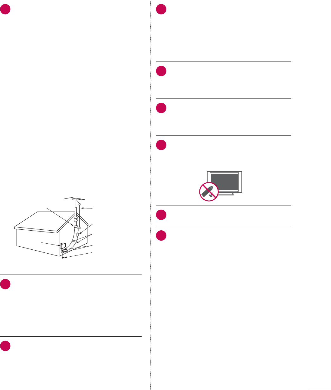
ANTENNAS
Outdoor antenna grounding
If an outdoor antenna is installed, follow the
precautions below. An outdoor antenna sys-
tem should not be located in the vicinity of
overhead power lines or other electric light or
power circuits, or where it can come in contact
with such power lines or circuits as death or
serious injury can occur.
Be sure the antenna system is grounded so as
to provide some protection against voltage
surges and built-up static charges.
Section 810 of the National Electrical Code
(NEC) in the U.S.A. provides information with
respect to proper grounding of the mast and
supporting structure, grounding of the lead-in
wire to an antenna discharge unit, size of
grounding conductors, location of antenna
discharge unit, connection to grounding elec-
trodes and requirements for the grounding
electrode.
Antenna grounding according to the National
Electrical Code, ANSI/NFPA 70
Antenna Lead in Wire
Antenna Discharge Unit
(NEC Section 810-20)
Grounding Conductor
(NEC Section 810-21)
Ground Clamps
Power Service Grounding
Electrode System (NEC
Art 250, Part H)
Ground Clamp
Electric Service
Equipment
NEC: National Electrical Code
21
Cleaning
When cleaning, unplug the power cord and
rub gently with a soft cloth to prevent
scratching. Do not spray water or other liquids
directly on the TV as electric shock may occur.
Do not clean with chemicals such as alcohol,
thinners or benzene.
22
Moving
Make sure the product is turned off, unplugged
and all cables have been removed. It may take
2 or more people to carry larger TVs. Do not
press against or put stress on the front panel
of the TV.
23
Ventilation
Install your TV where there is proper ventila-
tion. Do not install in a confined space such
as a bookcase. Do not cover the product
with cloth or other materials (e.g.) plastic
while plugged in. Do not install in exces-
sively dusty places.
24
Take care not to touch the ventilation open-
ings. When watching the TV for a long
period, the ventilation openings may
become hot.
25
If you smell smoke or other odors coming
from the TV or hear strange sounds, unplug
the power cord contact an authorized service
center.
26
Do not press strongly upon the panel with
hand or sharp object such as nail, pencil or
pen, or make a scratch on it.
27
Keep the product away from direct sunlight.
28
For LED LCD TV/LCD TV
If the TV feels cold to the touch, there may be
a small “flicker” when it is turned on. This is
normal, there is nothing wrong with TV.
Some minute dot defects may be visible on
the screen, appearing as tiny red, green, or
blue spots. However, they have no adverse
effect on the monitor's performance.
Avoid touching the LCD screen or holding
your finger(s) against it for long periods of
time. Doing so may produce some tempo-
rary distortion effects on the screen.

6
WARNING / CAUTION
............................2
SAFETY INSTRUCTIONS
........................3
CONTENTS
......................................................6
FEATURE OF THIS TV
............................. 8
PREPARATION
Accessories...........................................................10
Optional Extras ..................................................... 11
Front Panel Information ....................................12
Back Panel Information..................................... 17
Stand Instructions
.....................................................20
VESA Wall Mounting ........................................26
Cable Management ..........................................28
Desktop Pedestal Installation ..........................31
Swivel Stand .........................................................31
Attaching the TV to a Desk ............................32
Kensington Security System ..........................32
Securing the TV to the wall to prevent falling
when the tv is used on a stand.....................33
Antenna or Cable Connection.......................34
EXTERNAL EQUIPMENT SETUP
HD Receiver Setup............................................35
DVD SETUP.........................................................39
VCR SETUP.........................................................42
Other A/V Source Setup.................................44
USB Connection ................................................45
Headphone Setup
....................................................46
Audio Out Connection..................................... 47
External Equipment WIreless Connection
(Optional Extras).................................................48
PC Setup..............................................................49
Network Setup ....................................................55
WATCHING TV / CHANNEL CONTROL
Remote Control Functions ..............................63
Turning on the TV..............................................66
Channel Selection..............................................66
Volume Adjustment ..........................................66
Initial Setting ....................................................... 67
On-Screen Menus Selection ..........................69
Quick Menu .......................................................... 71
Customer Support
- Software Update............................................. 72
- Picture Test/Sound Test................................ 73
- Product/Service Info...................................... 74
- Network Test..................................................... 74
Simple Manual.................................................... 75
Channel Setup
- Auto Scan (Auto Tuning).............................. 76
- Add/Delete Channel (Manual Tuning) ..... 77
- Channel Editing............................................... 78
Favorite Channel Setup.................................... 79
Favorite Channel List ........................................ 79
Channel List ....................................................... 80
Channel Information .......................................... 81
Channel Brief Information...............................82
Input List ..............................................................83
Input Label...........................................................84
Reset to Factory Default (Initial Setting) .....85
Mode Setting ......................................................86
Demo Mode ........................................................ 87
AV Mode...............................................................88
Game.....................................................................89
SIMPLINK.............................................................90
MY MEDIA
Entry Mode ..........................................................92
Connection Method ..........................................93
Movie list............................................................. 102
Photo list............................................................. 109
Music list.............................................................. 115
DivX Registration Code.................................. 120
Deactivation ........................................................ 121
NETWORK
Legal Notice ...................................................... 122
CONTENTS

7
NETCAST
Netcast Menu.................................................... 123
YOUTUBE........................................................... 124
PICASA............................................................... 126
PICTURE CONTROL
Picture Size (Aspect Ratio) Control............ 128
Picture Wizard................................................... 130
ᰚEnergy Saving ............................................ 132
Preset Picture Settings (Picture Mode)..... 133
Manual Picture Adjustment - User Mode 134
Picture Improvement Technology (Advanced
Control) ............................................................... 135
Expert Picture control..................................... 136
Picture Reset..................................................... 139
TruMotion .........................................................140
LED Local Dimming ........................................141
Power Indicator ................................................ 142
Image Sticking Minimization (ISM) Method
.143
SOUND & LANGUAGE CONTROL
Auto Volume...................................................... 144
Clear Voice II ..................................................... 145
Balance ............................................................... 146
Preset Sound Settings (Sound Mode) .......147
Sound Setting Adjustment - User Mode.148
Audio Reset....................................................... 149
TV Speakers On/Off Setup .......................... 150
Stereo/SAP Broadcast Setup ....................... 151
Audio Language ............................................. 152
On-screen Menus Language Selection.... 153
Caption Mode
- Analog Broadcasting System Captions . 154
- Digital Broadcasting System Captions... 155
- Caption Option.............................................. 156
TIME SETTING
Clock Setting
- Auto Clock Setup ..........................................157
- Manual Clock Setup .................................... 158
Auto On/Off Time Setting............................ 159
Sleep Timer Setting ........................................ 160
PARENTAL CONTROL / RATINGS
Set Password & Lock System
- Setting up Your Password ............................161
- Set Password ................................................. 162
Lock System...................................................... 163
Channel Blocking............................................. 164
Movie & TV Rating .......................................... 165
Downloadable Rating.......................................170
External Input Blocking ....................................171
Key Lock ..............................................................172
APPENDIX
Troubleshooting.................................................173
Maintenance.......................................................176
Product Specifications ....................................177
IR Codes............................................................. 182
Open Source License..................................... 184

8
FEATURE OF THIS TV
ᯫ
Some of these features are not available on all models.
This TV contains the detailed cali-
brations necessary for professional
certification by the Imaging Science
Foundation. The resulting ISF “day”
and “night” modes will then be
accessible by the user to experi-
ence the best their LG HDTV has to
offer.
Sophisticated and detailed calibra-
tions can be made through the
ISFccc mode.
Detailed calibration requires a
licensed technician.
Please contact your local dealer to
inquire about an ISF certified tech-
nician.
THX (Thomlinson Holman’s
Experiment) is an audio and video
certification standard established
by George Lucas and Thomlinson.
A THX certified display guarantees
screen quality that exceeds the dis-
play standard specification in both
hardware and software.
A unique invisible speaker system
tuned by renowned audio expert,
Mr. Mark Levinson. Speakers are
embedded in strategic spots
behind the front cabinet and use
minute vibrations to turn the entire
front bezel into the speaker system.
The result s a clean, polished look,
and enhanced audio by increasing
the “sweet spot”, giving a wider and
richer sound field.
Unlike other sensors which can only
sense brightness of ambient light,
LG’s “Intelligent Sensor” uses
4,096 sensing steps to evaluate its
surroundings. Using a sophisticat-
ed algorithm, the LG processes
picture quality elements including
brightness, contrast, color, sharp-
ness and white balance. The result
is a picture optimized for it’s sur-
roundings, more pleasing to watch
and which can also save up to 50%
in power consumption.
High-definition television. High-
resolution digital television broad-
cast and playback system com-
posed of roughly a million or more
pixels, 16:9 aspect-ratio screens,
and AC3 digital audio. A subset of
digital television, HDTV formats
include 1080p, 1080i, and 720p
resolutions.
Manufactured under license from
Dolby Laboratories. “Dolby “and the
double-D symbol are trademarks of
Dolby Laboratories.
HDMI, the HDMI logo and High-
Definition Multimedia Interface are
trademarks or registered trade-
marks of HDMI Licensing LLC."
Displays HDTV programs in full
1920 x 1080p resolution for a more
detailed picture.
ABOUT DIVX VIDEO: DivX® is a
digital video format created by
DivX,Inc. This is an official DivX
Certified device that plays DivX
video. Visit www.divx.com for more
information and software tools to
convert your files into DivX video.
ABOUT DIVX VIDEO-ON-
DEMAND: This DivX Certified®
device must be registered in order
to play DivX Video-on-Demand
(VOD) content. To generate the
registration code, locate the DivX
VOD section in the device setup
menu. Go to vod.divx.com with this
code to complete the registration
process and learn more about
DivX VOD.
“DivX Certified to play DivX video
up to HD 1080p, including premi-
um content”
“Pat. 7,295,673; 7,460,688;7,519,274”
9
IMPORTANT INFORMATION TO PREVENT “IMAGE
BURN / BURN-IN” ON YOUR TV SCREEN
ᯫ
When a fixed image (e.g. logos, screen menus, video game, and computer display) is displayed
on the TV for an extended period, it can become permanently imprinted on the screen. This
phenomenon is known as “image burn” or “burn-in.” Image burn is not covered under the man-
ufacturer’s warranty.
ᯫ
In order to prevent image burn, avoid displaying a fixed image on your TV screen for a prolonged
period (2 or more hours for LCD, 1 or more
hours for Plasma).
ᯫ
Image burn can also occur on the letter-
boxed areas of your TV if you use the 4:3
aspect ratio setting for an extended period.
ON DISPOSAL
(Only Hg lamp used LCD TV)
The fluorescent lamp used in this product contains a small amount of mercury. Do not dispose of this
product with general household waste. Disposal of this product must be carried out in accordance to
the regulations of your local authority.
View videos and photos and listen
to music on your TV through USB
2.0 (‘videos’ dependent on model).
AV Mode is three preset picture
and audio settings. It allows the
viewer to quickly switch between
common settings. It includes
Cinema, Sports, and Game Modes.
Automatically enhances and ampli-
fies the sound of human voice fre-
quency range to help keep dia-
logue audible when background
noise swells.
PREPARATION
PREPARATION
10
ACCESSORIES
PREPARATION
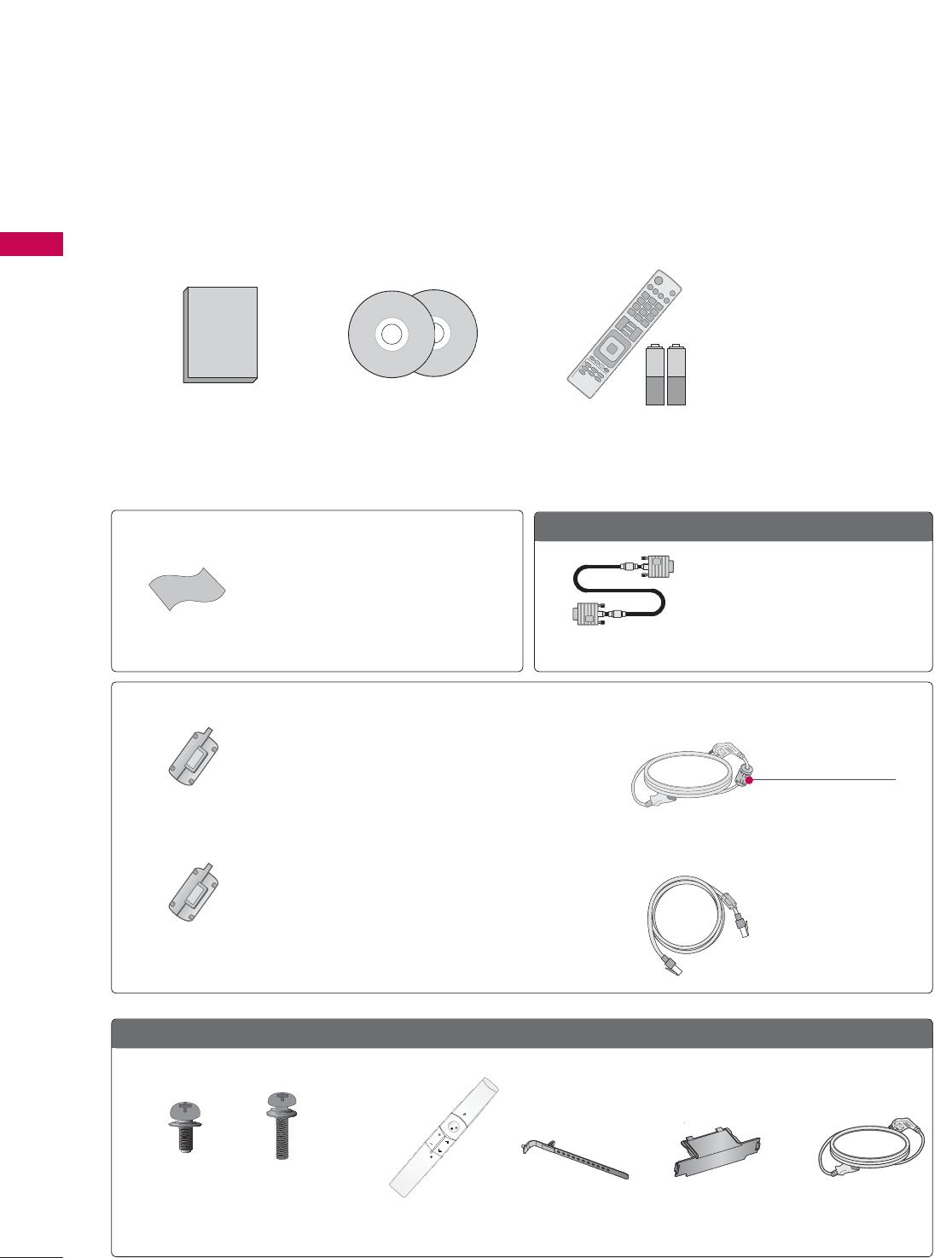
Ensure that the following accessories are included with your TV. If an accessory is missing, please con-
tact the dealer where you purchased the TV.
The accessories included may differ from the images below.
Option Extras
* Wipe spots on the exterior only with the
polishing cloth.
* Do not wipe roughly when removing
stains. Excessive pressure may cause
scratches or discoloration.
Polishing Cloth
Not included with all models
Not included with all models
D-sub 15 pin Cable
When using the VGA (D-sub 15
pin cable) PC connection, the user
must use shielded signal interface
cables with ferrite cores to main-
tain standards compliance.
Power Cord
1.5V 1.5V
Owner’s Manual CD Manual,
Nero MediaHome 4
Essentials CD
Remote Control,
Batteries (AAA)
50/60PK750, 50/60PK950
(For 50PK750) (For 50/60PK950)
Protection Cover
(Refer to p.21)
Motion Remote
Control
Cable Holder
(Refer to p.28)
x 2
x 3 x 4
Screws for stand assembly
(Refer to P.20)
ENTER
VOL
MUTE
CH
(M5 x 14) (M4 x 28)
Ferrite Core
(Black)
Ferrite Core
(White)
Close to the wall plug.
Ferrite core can be used to reduce the electromagnetic
waves that may interfere with the TV. Install the Ferrite
core on the power cable close to the wall plug.
Ferrite core can be used to reduce the electromagnetic
wave when connecting the LAN cable. Place the ferrite
core far from TV and wind the LAN cable in the ferrite
core once.
11
PREPARATION
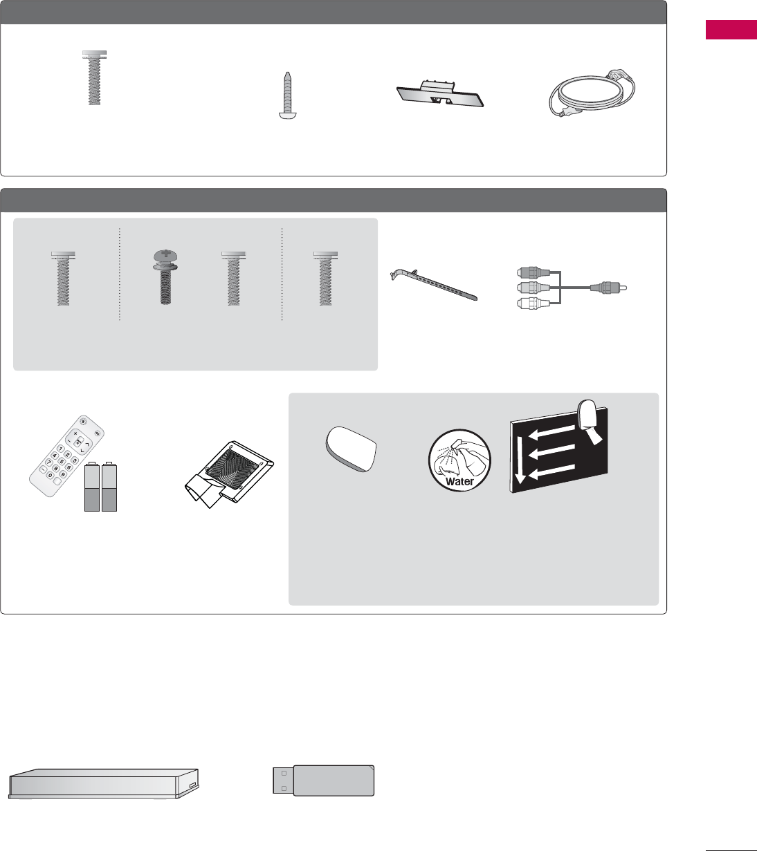
OPTIONAL EXTRAS
Optional extras can be changed or modified for quality improvement without any notification.
Contact your dealer for buying these items.
This device only works with compatible LG LED LCD TV, LCD TV, or Plasma TV.
32/42/46/52/60LD550, 47/55LD650
Protection Cover
(Refer to P.23)
Power Cord
Wireless Media Box
(AN-WL100W)
Wireless LAN for Broadband/
DLNA Adaptor
(AN-WF100)
(M4 x 20)
Screws for stand assembly
(Refer to P.22)
Screw for stand fixing
(Refer to P.32)
x 8
42/47/55LE5400, 42/47/55LE5500, 42/47/55LE7500, 47/55LE8500
Cable Holder
(Refer to p.30)
Component gender cable,
AV gender cable
Screws for stand assembly
(Refer to P.24)
Simple Remote Control,
Batteries (AAA)
Stand Rear Cover
x 8 x 8x 4x 4 x 2
(M4 x 20) (M4 x 16)(M4 x 16)(M4 x 24)
(47/55LE8500) (Other models)(55LE5500, 55LE7500)
(For 42/47/55LE7500,
47/55LE8500) (For 42/47/55LE7500)
(For 32/42LD550)
* Wipe spots on the exterior only with the polishing cloth.
* Do not wipe roughly when removing stains. Excessive pressure may cause
scratches or discoloration.
* For cleaning front frame, please slowly wipe in one direction after spraying
water 1-2 times on cleansing cloths. Please remove excessive moisture
after cleaning. Excessive moisture may cause water stains on the frame.
1.5V 1.5V
CH
FLASHBK
VOL
POW
ER TV/
INPUT
Polishing Cloth
PREPARATION
PREPARATION
12
ᯫ
Image shown may differ from your TV.
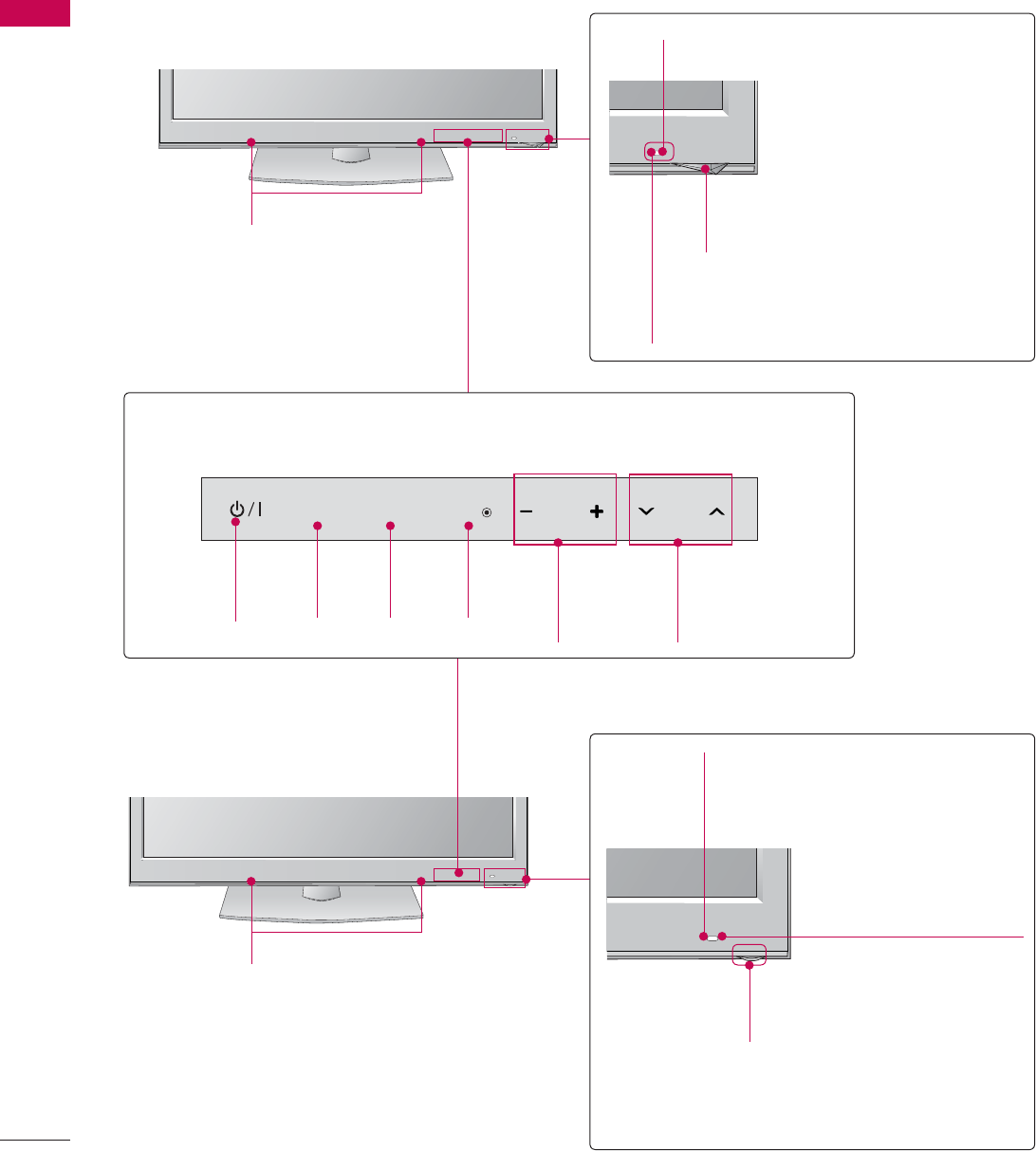
50/6OK750
FRONT PANEL INFORMATION
SPEAKER
Remote Control Sensor
Intelligent Sensor
Adjusts picture according to the
surrounding conditions
Power/Standby Indicator
Illuminates red in standby mode.
50/60PK950
SPEAKER Remote Control Sensor
Intelligent Sensor
Adjusts picture according to the
surrounding conditions
Power/Standby Indicator
Illuminates red in standby mode.
The lighting is off while the TV remains on.
Touch Button
You can operate the button just by touching the button lightly with your finger.
ENTER CH
VOL
MENU
INPUT
CHANNEL
(ᰝ,ᰜ)
Buttons
VOLUME
(-, +)
Buttons
ENTER
Button
MENU
Button
INPUT
Button
POWER
Button
17
PREPARATION
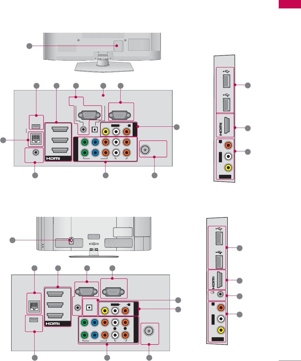
BACK PANEL INFORMATION
ᯫ
Image shown may differ from your TV.
ANTENNA
/CABLE
IN
RGB IN (PC)
LAN
WIRELESS
CONTROL
REMOTE CONTROL IN
AUDIO IN
(RGB/DVI)
SERVICE ONLY
O
PTICAL
DIGITAL
AUDIO OUT
/DVI IN
2
3
1
2
1
VIDEO
AUDIO
L(MONO)
R
VIDEO AUDIO
COMPONENT IN
AV IN 1
YLR
P
B
P
R
DVI IN 4
USB IN 1 USB IN 2
AV IN 2
VIDEO
AUDIO
L(MONO)
R
50/60PK750, 50/60PK950
1
2 3 45
6
7813
910
2
6
12
CABLE MANAGEMENT
AC IN
ANTENNA/
CABLE IN
RGB IN (PC)
LAN
WIRELESS
CONTROL
AUDIO IN
AUDIO OUT
RGB/DVI
RS-232C IN
(
SERVICE ONLY)
OPTICAL DIGITAL
/DVI IN
2
3
1
2
1
VIDEO
AUDIO
L(MONO)
R
VIDEO AUDIO
COMPONENT INAV IN 1
YP
B
P
R
ꔡ
LR
IN 4
H/P USB IN 1 USB IN 2
AV IN 2
VIDEO
AUDIO
L/MONO
R
1
12
2 3 4
5
6
789
32/42/46/52/60LD550, 47/55LD650
10
2
11
6

19
PREPARATION
1LAN
Network connection for Netflix, Yahoo! TV
Widgets, etc (for USA).
Also used for video, photo and music files on
a local network.
2HDMI/DVI IN, HDMI IN
Digital Connection.
Supports HD video and Digital audio. Doesn’t
support 480i.
Accepts DVI video using an adapter or HDMI
to DVI cable (not included).
3RGB IN (PC)
Analog PC Connection. Uses a D-sub 15 pin
cable (VGA cable).
AUDIO IN (RGB/DVI)
0.32 cm (1/8 inch) headphone jack for analog
PC audio input.
4
RS-232C IN (SERVICE ONLY),SERVICE ONLY
This port is used for service.
5OPTICAL DIGITAL AUDIO OUT
Digital optical audio output for use with amps
and home theater systems.
Note: In standby mode, this port doesn’t work.
6AV (Audio/Video) IN
Analog composite connection. Supports
standard definition video only (480i).
7ANTENNA/CABLE IN
Connect over-the-air or cable signals to this
jack.
8COMPONENT IN
Analog Connection.
Supports HD.
Uses a red, green, and blue cable for video &
red and white for audio.
9WIRELESS CONTROL
Connect the Wireless Ready Dongle to the TV
to control the external input devices con-
nected to Media Box wirelessly.
10 USB INPUT
Used for viewing photos, watching movies
and listening to MP3s.
11 HEADPHONE
0.32 cm (1/8 inch) headphone jack
Impedance 16 Ω , Maximum audio out 15 mW
12 Power Cord or Socket
For operation with AC power.
Caution: Never attempt to operate the TV on
DC power.
13 REMOTE CONTROL IN
For a wired remote control.
PREPARATION
PREPARATION
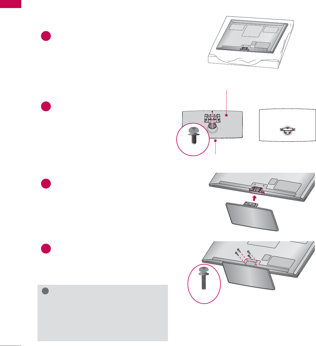
20
STAND INSTRUCTIONS
(For 50/60PK750, 50/60PK950)
ᯫ
Image shown may differ from your TV.
INSTALLATION (For 50PK750, 50PK950)
!
NOTE
ŹWhen assembling the desk type stand,
make sure the screws are fully tightened (If
not tightened fully, the TV can tilt forward
after the product installation). Do not over
tighten.
1Carefully place the TV screen side down on
a cushioned surface to protect the screen
from damage.
2Assemble the parts of the STAND BODY
with the STAND BASE of the TV.
3Assemble the TV as shown.
4Install the 4 screws into the holes shown.
STAND BASE
STAND BODY
M5 x 14
M4 x 28
21
PREPARATION
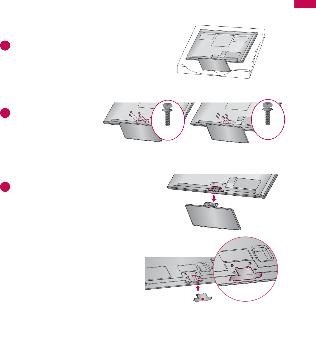
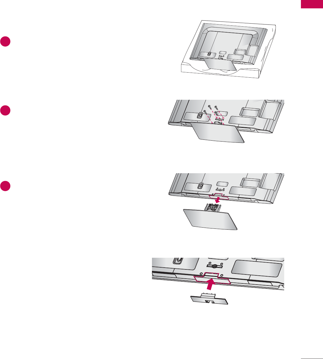
DETACHMENT
PROTECTION COVER
After removing the stand, install the included
PROTECTION COVER over the hole for the
stand.
Press the PROTECTION COVER into the TV until
you hear it click.
When installing the wall mounting bracket, use
the PROTECTION COVER.
1Carefully place the TV screen side down on
a cushioned surface to protect the screen
from damage.
2Remove the screws that
hold the stand on.
3Detach the stand from TV.
PROTECTION COVER
Fix a guide to the outside.
50PK750 60PK750
M4 x 30
M4 x 28
PREPARATION
PREPARATION
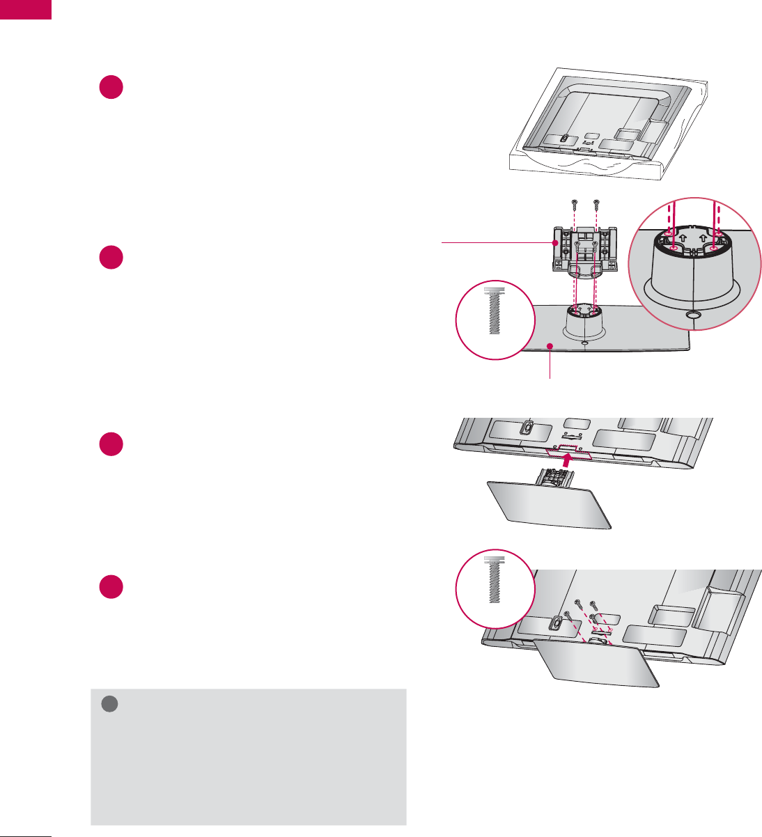
22
STAND INSTRUCTIONS
(For 32/42/46/52/60LD550, 47/55LD650)
ᯫ
Image shown may differ from your TV.
!
NOTE
ŹWhen assembling the desk type stand,
make sure the screws are fully tightened (If
not tightened fully, the TV can tilt forward
after the product installation). Do not over
tighten.
1Carefully place the TV screen side down on
a cushioned surface to protect the screen
from damage.
2Assemble the parts of the STAND BODY
with the STAND BASE of the TV.
3Assemble the TV as shown.
4Install the 4 screws into the holes shown.
AC IN
CABLE MANAGEMENT
AC IN
CABLE MANAGEMENT
AC IN
CABLE MANAGEMENT
STAND BASE
STAND BODY
INSTALLATION
M4 x 20
M4 x 20
23
PREPARATION
AC IN
CABLE MANAGEMENT
AC IN
CABLE MANAGEMENT
DETACHMENT
AC IN
CABLE MANAGEMENT
PROTECTION COVER
After removing the stand, install the included
PROTECTION COVER over the hole for the
stand.
Press the PROTECTION COVER into the TV until
you hear it click.
When installing the wall mounting bracket, use
the PROTECTION COVER.
1Carefully place the TV screen side down on
a cushioned surface to protect the screen
from damage.
2Remove the screws that hold the stand on.
3Detach the stand from TV.
PREPARATION
PREPARATION
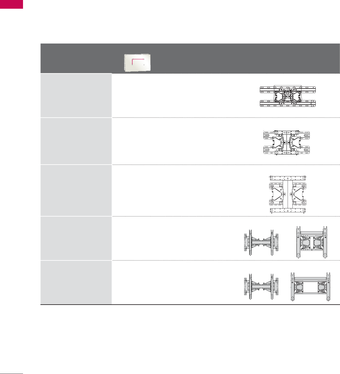
26
VESA WALL MOUNTING
Install your wall mount on a solid wall perpendicular to the floor. When attaching to other building mate-
rials, please contact your nearest installer.
If installed on a ceiling or slanted wall, it may fall and result in severe personal injury.
We recommend that you use an LG brand wall mount when mounting the TV to a wall.
LG recommends that wall mounting be performed by a qualified professional installer.
Model
VESA (A * B)
A
B
Standard
Screw Quantity Wall Mounting Bracket
(sold separately)
32LD550 200 * 100 M4 4
LSW100B, LSW100BG
42/46LD550,
47LD650,
42/47LE5400,
42/47LE5500,
42/47LE7500,
47LE8500
200 * 200 M6 4
LSW200B, LSW200BG
52LD550, 55LD650,
55LE5400,
55LE5500,
55LE7500,
55LE8500,
60LD550
400 * 400 M6 4
LSW400B, LSW400BG
50PK750 400 * 400 M6 4
AW-50PG60M AW-50PG60MS
60PK750 600 * 400 M8 4
AW-60PG60M AW-60PG60MS

27
PREPARATION
CAUTION
ŹDo not install your wall mount kit while your TV is turned on. It may result in personal injury due to
electric shock.
!
NOTE
ŹScrew length needed depends on the wall
mount used. For further information, refer to
the instructions included with the mount.
ŹStandard dimensions for wall mount kits are
shown in the table.
ŹWhen purchasing our wall mount kit, a detailed
installation manual and all parts necessary for
assembly are provided.
ŹDo not use screws longer than the standard
dimension, as they may cause damage to the
inside to the TV.
ŹFor wall mounts that do not comply with the
VESA standard screw specifications, the length
of the screws may differ depending on their
specifications.
ŹDo not use screws that do not comply with the
VESA standard screw specifications.
Do not use fasten the screws too strongly, this
may damage the TV or cause the TV to a fall,
leading to personal injury. LG is not liable for
these kinds of accidents.
ŹLG is not liable for TV damage or personal
injury when a non-VESA or non specified wall
mount is used or the consumer fails to follow
the TV installation instructions.
PREPARATION
PREPARATION
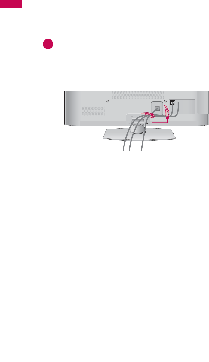
28
CABLE MANAGEMENT
ᯫ
Image shown may differ from your TV.
Plasma TV
CABLE HOLDER
1
After connecting the cables as necessary,
install the CABLE HOLDER as shown
and bundle the cables.
In case of the LAN cable, install as
shown to reduce the electromagnetic
wave.
PREPARATION
PREPARATION
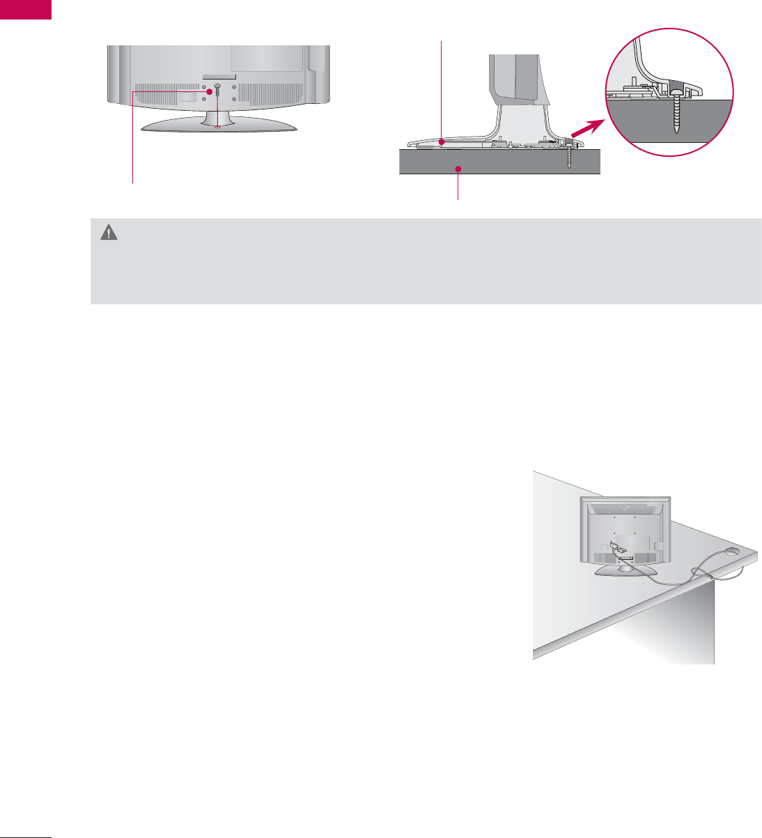
32
ATTACHING THE TV TO A DESK (For
32/42LD550
)
The TV must be attached to a desk so it cannot be pulled in a forward/backward direction, poten-
tially causing injury or damaging the product.
1-Screw
(provided as parts of the product)
Desk
Stand
KENSINGTON SECURITY SYSTEM
ᯫ
This feature is not available for all models.
- The TV is equipped with a Kensington Security System con-
nector on the back panel. Connect the Kensington Security
System cable as shown below.
- For the detailed installation and use of the Kensington Security
System, refer to the user’s guide provided with the Kensington
Security System.
For further information, contact http://www.kensington.com,
the internet homepage of the Kensington company. Kensington
sells security systems for expensive electronic equipment such
as notebook PCs and LCD projectors.
NOTE: The Kensington Security System is an optional accessory.
WARNING
ŹTo prevent TV from falling over, the TV should be securely attached to the floor/wall per installa-
tion instructions. Tipping, shaking, or rocking the machine may cause injury.
ᯫ
Image shown may differ from your TV.
33
PREPARATION
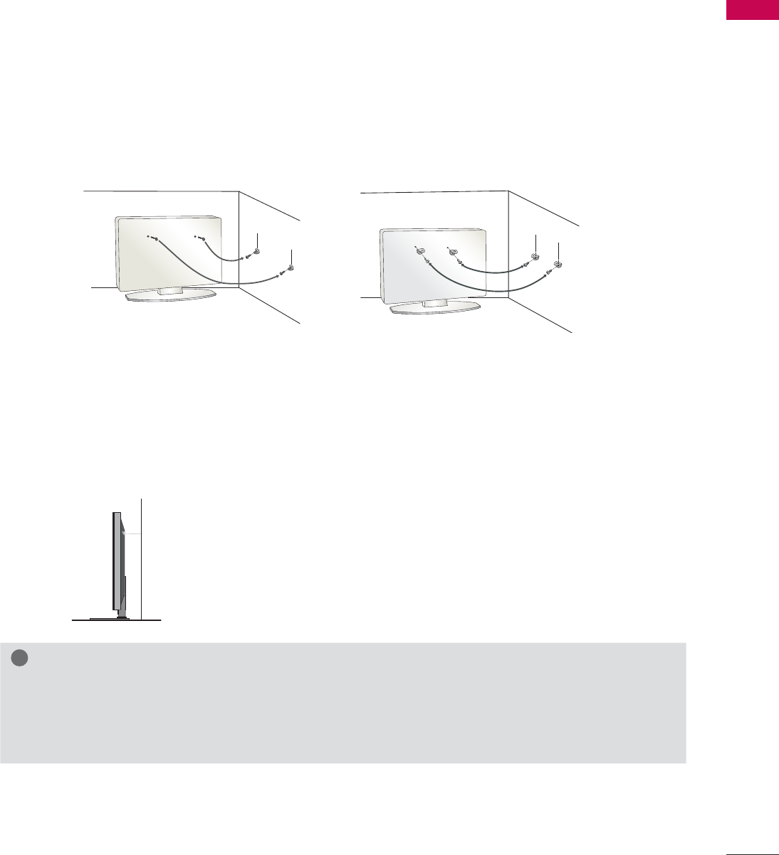
SECURING THE TV TO THE WALL TO PREVENT FALLING
WHEN THE TV IS USED ON A STAND
We recommend that you set up the TV close to a wall so it cannot fall over if pushed backwards.
Additionally, we recommend that the TV be attached to a wall so it cannot be pulled in a forward
direction, potentially causing injury or damaging the product.
Caution: Please make sure that children don’t climb on or hang from the TV.
ᯫ
Insert the eye-bolts (or TV brackets and bolts) to tighten the product to the wall as shown in the
picture.
* If your product has the bolts in the eye-bolts position before inserting the eye-bolts, loosen the
bolts.
* Insert the eye-bolts or TV brackets/bolts and tighten them securely in the upper holes.
Secure the wall brackets with the bolts (sold separately) to the wall. Match the height of the bracket
that is mounted on the wall to the holes in the product.
Ensure the eye-bolts or brackets are tightened securely.
ᯫ
Use a sturdy rope (sold separately) to tie the product. It is safer to tie the
rope so it becomes horizontal between the wall and the product.
ᯫ
You should purchase necessary components to prevent the TV from tipping over (when not using a
wall mount).
ᯫ
Image shown may differ from your TV.
!
NOTE
ŹUse a platform or cabinet strong enough and large enough to support the size and weight of
the TV.
ŹTo use the TV safely make sure that the height of the bracket on the wall and the one on the TV are
the same.
PREPARATION
PREPARATION
34
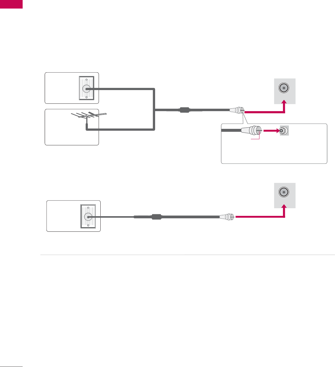
ANTENNA OR CABLE CONNECTION
ᯫ
To prevent damage do not connect to the power outlet until all connections are made between the
devices.
ᯫ
Image shown may differ from your TV.
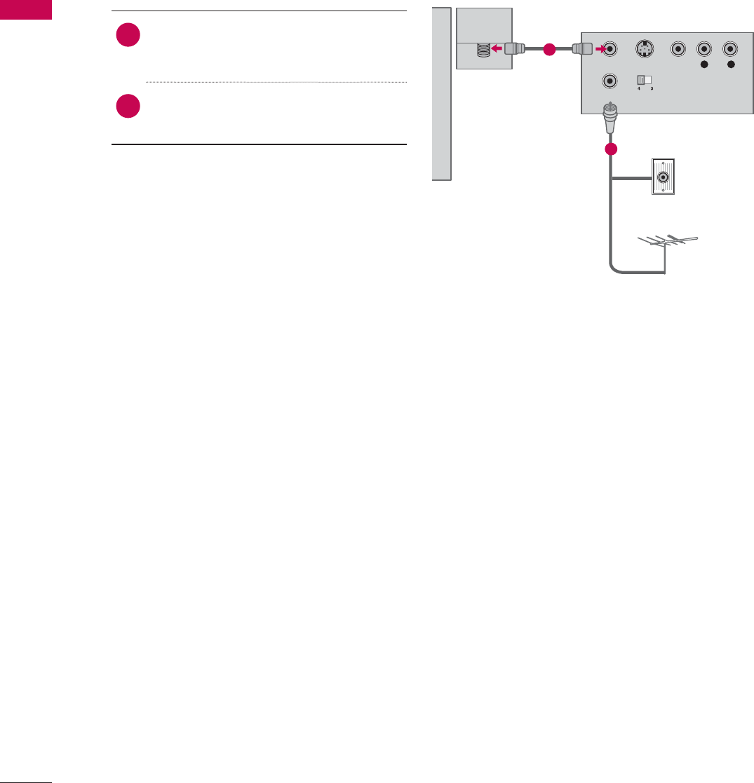
1. Antenna (Analog or Digital)
Wall Antenna Socket or Outdoor Antenna without a Cable Box Connections.
For optimum picture quality, adjust antenna direction if needed.
2. Cable
Wall
Antenna
Socket
Outdoor
Antenna
(VHF, UHF)
Cable TV
Wall Jack
Multi-family Dwellings/Apartments
(Connect to wall antenna socket)
RF Coaxial Wire (75 Ω)
RF Coaxial Wire (75 Ω)
Single-family Dwellings /Houses
(Connect to wall jack for outdoor antenna)
Be careful not to bend the copper wire
when connecting the antenna.
Copper Wire
ᯫ
If the antenna needs to be split for two TV’s, install a 2-Way Signal Splitter.
ᯫ
For much more information about antennas visit our Knowledgebase at http://lgknowledgebase.
com. Search for antenna.
ANTENNA/
CABLE IN
ANTENNA/
CABLE IN
35
EXTERNAL EQUIPMENT SETUP
HD RECEIVER SETUP
ᯫ
To prevent the equipment damage, never plug in any power cords until you have finished connecting all
equipment.
ᯫ
I
mage shown may differ from your TV.
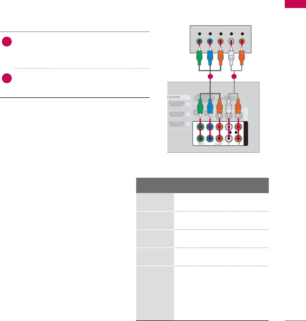
1. How to connect
1Connect the video outputs (Y, P B, PR) of the
digital set-top box to the COMPONENT IN
VIDEO 1, 2,or3* jacks on the TV. Match the
jack colors (Y = green, PB = blue, and PR = red).
2Connect the audio output of the digital set-top
box to the COMPONENT IN AUDIO 1, 2,or3*
jacks on the TV.
2. How to use
ᯫ
Turn on the digital set-top box.
(Refer to the owner’s manual for the digital set-
top box operation.)
ᯫ
Select the Component1,Component2, or
Component3 input source on the TV using the
INPUT button on the remote control.
Component Connection
This TV can receive digital over-the-air/digital cable signals without an external digital set-top box.
However, if you do receive digital signals from a digital set-top box or other digital external device.
EXTERNAL EQUIPMENT SETUP
RGB IN (PC)
(RGB/DVI)
RS-232C IN
(
SERVICE ONLY)
OPTICAL
DIGITAL
/DVI IN
2
3
1
VIDEO
AUDIO
L(MONO)
R
AV IN 1
AUDIO IN
AUDIO OUT
VIDEO AUDIO
COMPONENT IN
YP
B
P
R
L R
2
1
Y L RP
B
P
R
1 2
Y, C B/PB, CR/PR
Resolution Horizontal
Frequency(KHz)Vertical
Frequency(KHz)
720x480i 15.73 59.94
15.73 60.00
720x480p 31.47 59.94
31.50 60.00
1280x720p 44.96 59.94
45.00 60.00
1920x1080i
33.72 59.94
33.75 60.00
1920x1080p
26.97 23.976
27.00 24.00
33.71 29.97
33.75 30.00
67.432 59.94
67.50 60.00
* Component3: For LED LCD TV
37
EXTERNAL EQUIPMENT SETUP
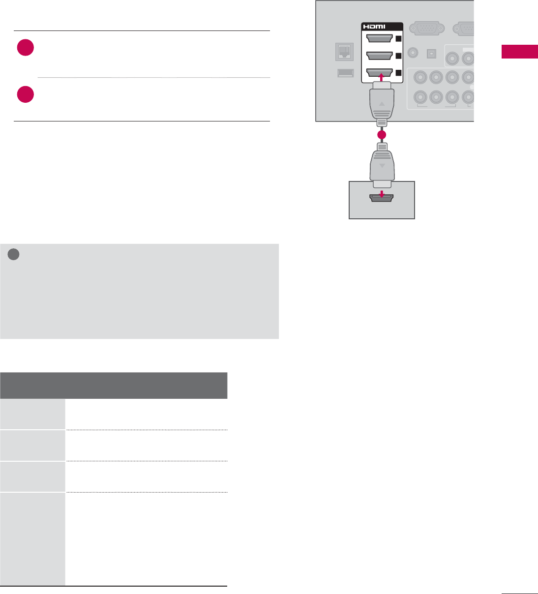
HDMI Connection
1. How to connect
1Connect the digital set-top box to HDMI/DVI IN
1,2,3, or 4jack on the TV.
2No separate audio connection is necessary.
HDMI supports both audio and video.
2. How to use
ᯫ
Turn on the digital set-top box.
(Refer to the owner’s manual for the digital set-
top box.)
ᯫ
Select the HDMI1,HDMI2,HDMI3, or HDMI4 input
source on the TV using the INPUT button on the
remote control.
!
NOTE
ŹIf an HDMI cable doesn’t support HDMI version 1.3, it
can cause flickers or no screen display. In this case
use the latest cables that support HDMI version 1.3.
ŹHDMI Audio Supported Format: Dolby Digital (32 KHz, 44.1
KHz, 48 KHz), Linear PCM (32 KHz, 44.1 KHz, 48 KHz)
HDMI-DTV
Resolution Horizontal
Frequency(KHz)Vertical
Frequency(KHz)
720x480p 31.47 59.94
31.50 60.00
1280x720p 44.96 59.94
45.00 60.00
1920x1080i
33.72 59.94
33.75 60.00
1920x1080p
26.97 23.976
27.00 24.00
33.71 29.97
33.75 30.00
67.432 59.94
67.50 60.00
HDMI OUTPUT
RGB IN (PC)
LAN
WIRELESS
CONTROL
(RGB/DVI)
VIDEO
L(MONO
VIDEO A
AUDIO IN
AUDIO OUT
2
1
/DVI IN
2
3
1
YP
B
P
R
L
OPTICAL DIGITAL
RS-23
2
(
SERVICE
ꔡ
1
EXTERNAL EQUIPMENT SETUP
EXTERNAL EQUIPMENT SETUP
38
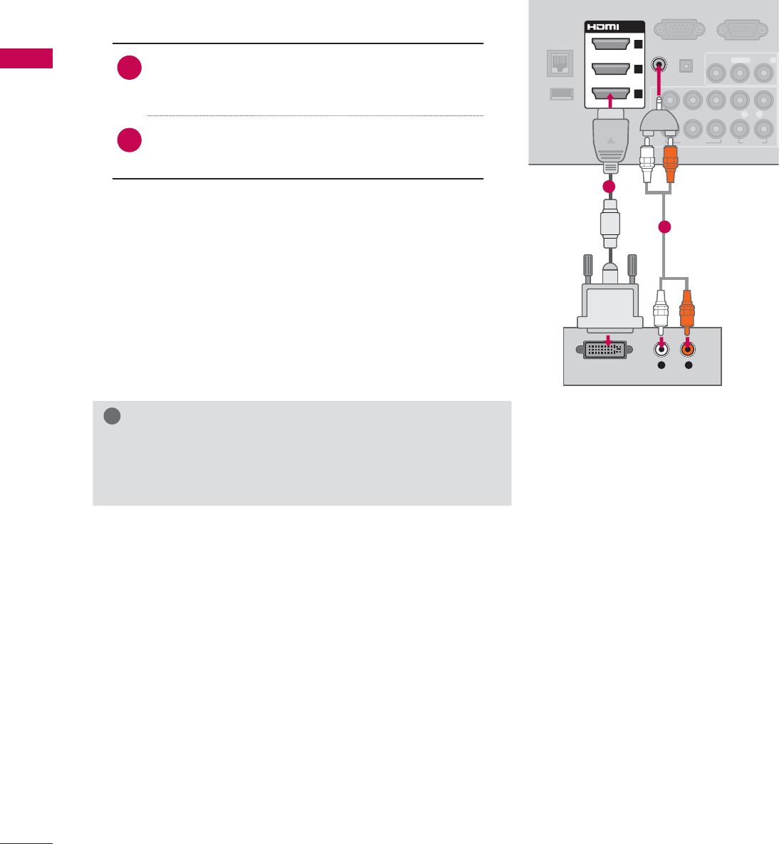
DVI to HDMI Connection
1. How to connect
1Connect the DVI output of the digital set-top
box to the HDMI/DVI IN 1,2,3, or 4* jack on
the TV.
2Connect the digital set-top box audio output to
the AUDIO IN (RGB/DVI) jack on the TV.
2. How to use
ᯫ
Turn on the digital set-top box.
(Refer to the owner’s manual for the digital set-
top box.)
ᯫ
Select the HDMI1,HDMI2,HDMI3, or HDMI4* input
source on the TV using the INPUT button on the
remote control.
!
NOTE
ŹA DVI to HDMI cable or adapter is required for this con-
nection. DVI doesn't support audio, so a separate audio
connection is necessary.
L R
DVI OUTPUT
AUDIO
RGB IN (PC)
LAN
WIRELESS
CONTROL
RS-232C IN
(
SERVICE ONLY)
VIDEO
AUDIO
L(MONO)
R
VIDEO AUDIO
YP
B
P
R
L R
AUDIO OUT
2
1
/DVI IN
2
3
1
(RGB/DVI)
AUDIO IN
OPTICAL DIGITAL
ꔡ
1
2
* HDMI4: For Plasma TV
39
EXTERNAL EQUIPMENT SETUP
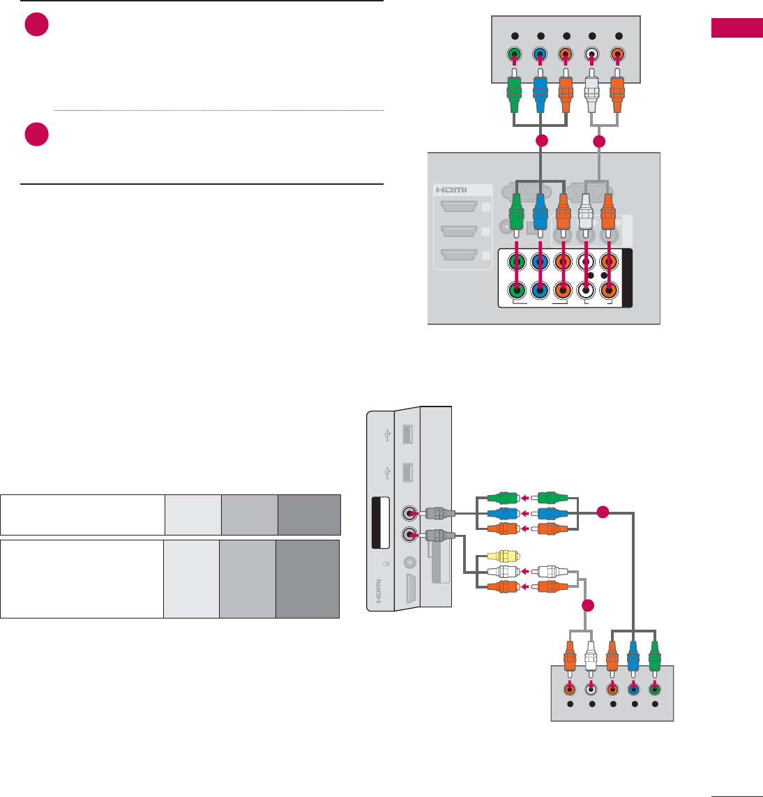
DVD SETUP
Component Input ports
To get better picture quality, connect a DVD player
to the component input ports as shown below.
1. How to connect
1Connect the video outputs (Y, P B, PR) of the
DVD to the COMPONENT IN VIDEO 1, 2,or3*
jacks on the TV.
Match the jack colors (Y = green, PB = blue, and
PR = red).
2Connect the audio outputs of the DVD to the
COMPONENT IN AUDIO 1, 2,or3* jacks on the
TV.
2. How to use
ᯫ
Turn on the DVD player, insert a DVD.
ᯫ
Select the Component1, Component2, or
Component3 input source on the TV using the
INPUT button on the remote control.
ᯫ
Refer to the DVD player’s manual for operating
instructions.
Component Connection
RGB IN (PC)
S
L
(RGB/DVI)
/DVI IN
2
3
1
VIDEO
AUDIO
L(MONO)
R
AV IN 1
AUDIO IN
AUDIO OUT
VIDEO AUDIO
COMPONENT IN
YP
B
P
R
L R
2
1
Y L RP
B
P
R
OPTICAL DIGITAL
RS-232C IN
(
SERVICE ONLY)
12
* Component3: For LED LCD TV
Component ports on
the TV
YP
B
P
R
Video output ports
on DVD player
YP
B
P
R
YB-YR-Y
YCbCr
YPb Pr
YLR P
B
P
R
AUDIO / Y P
B
P
R
IN 4
H/P USB IN 1 USB IN 2
AV IN2
VIDEO / AUDIO
COMPONENT IN3
1
2
For LED LCD TV
EXTERNAL EQUIPMENT SETUP
EXTERNAL EQUIPMENT SETUP
40
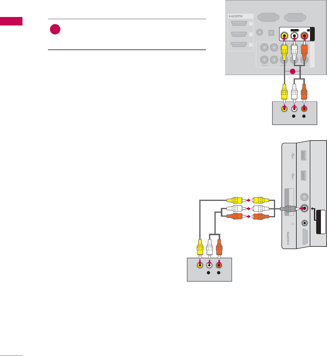
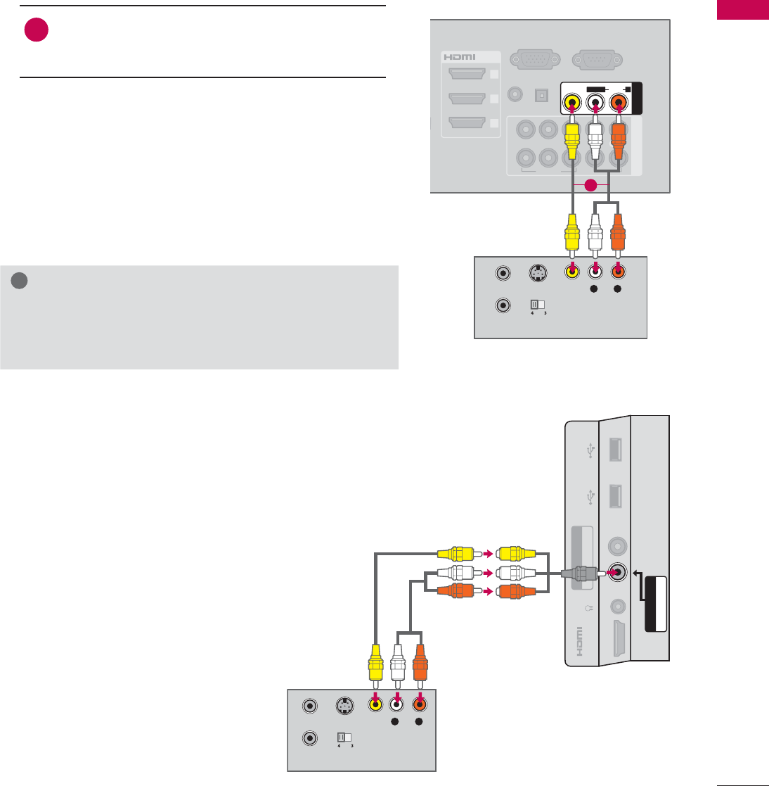
Composite (RCA) Connection
1. How to connect
1Connect the AUDIO/VIDEO jacks between TV
and DVD. Match the jack colors (Video = yellow,
Audio Left = white, and Audio Right = red)
2. How to use
ᯫ
Turn on the DVD player, insert a DVD.
ᯫ
Select the AV1 or AV2 input source on the TV
using the INPUT button on the remote control.
ᯫ
Refer to the DVD player's manual for operating
instructions.
RGB IN (PC)
S
L
(RGB/DVI)
/DVI IN
2
3
1
VIDEO AUDIO
COMPONENT IN
AUDIO IN
AUDIO OUT
2
1
VIDEO
AUDIO
L(MONO)
R
AV IN 1
YP
B
P
R
L R
OPTICAL DIGITAL
RS-232C IN
(
SERVICE ONLY)
L R
VIDEO
AUDIO
1
L R
VIDEO
AUDIO
AUDIO / Y P
B
P
R
IN 4
H/P USB IN 1 USB IN 2
VIDEO / AUDIO
COMPONENT IN3
AV IN2
For LED LCD TV
41
EXTERNAL EQUIPMENT SETUP
HDMI OUTPUT
RGB IN (PC)
LAN
WIRELESS
CONTROL
(RGB/DVI)
VIDEO
AUDIO
L(MONO)
R
VIDEO AUDIO
COMPONENT INAV IN 1
AUDIO IN
AUDIO OUT
2
1
/DVI IN
2
3
1
YP
B
P
R
L R
OPTICAL DIGITAL
RS-232C IN
(
SERVICE ONLY)
ꔡ
1
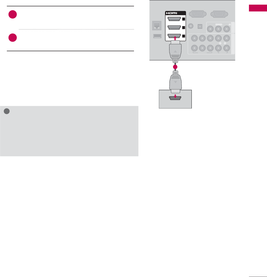
HDMI Connection
1. How to connect
1Connect the HDMI output of the DVD to the
HDMI/DVI IN 1,2,3or 4 jack on the TV.
2No separate audio connection is necessary.
HDMI supports both audio and video.
2. How to use
ᯫ
Select the HDMI1,HDMI2,HDMI3, or HDMI4 input
source on the TV using the INPUT button on the
remote control.
ᯫ
Refer to the DVD player's manual for operating
instructions.
!
NOTE
ŹIf an HDMI cable doesn’t support HDMI version 1.3, it
can cause flickers or no screen display. In this case
use the latest cables that support HDMI version 1.3.
ŹHDMI Audio Supported Format: Dolby Digital (32 KHz, 44.1
KHz, 48 KHz), Linear PCM (32 KHz, 44.1 KHz, 48 KHz)
EXTERNAL EQUIPMENT SETUP
EXTERNAL EQUIPMENT SETUP
42
VCR SETUP
Antenna Connection
ANTENNA/
CABLE IN
L R
S-VIDEO VIDEO
AUDIO
OUTPUT
SWITCH
ANT IN
ANT OUT
Wall Jack
Antenna
1. How to connect
1Connect the RF antenna out socket
of the VCR to the ANTENNA/CABLE
IN socket on the TV.
2Connect the antenna cable to the RF
antenna in socket of the VCR.
2. How to use
ᯫ
Set VCR output switch to 3 or 4 and
then tune TV to the same channel num-
ber.
ᯫ
Insert a video tape into the VCR and
press PLAY on the VCR (Refer to the
VCR owner’s manual).
1
2
43
EXTERNAL EQUIPMENT SETUP
Composite (RCA) Connection
S-VIDEO
OUTPUT
SWITCH
ANT IN
ANT OUT
RGB IN (PC)
S
S
O
L
(RGB/DVI)
/DVI IN
2
3
1
VIDEO AUDIO
COMPONENT IN
AUDIO IN
AUDIO OUT
2
1
VIDEO
AUDIO
L(MONO)
R
AV IN 1
YP
B
P
R
L R
OPTICAL DIGITAL
RS-232C IN
(
SERVICE ONLY)
L R
VIDEO
AUDIO
1. How to connect
1Connect the AUDIO/VIDEO jacks between TV
and VCR. Match the jack colors (Video = yellow,
Audio Left = white, and Audio Right = red)
2. How to use
ᯫ
Insert a video tape into the VCR and press PLAY
on the VCR. (Refer to the VCR owner’s manual.)
ᯫ
Select the AV1 or AV2 input source on the TV
using the INPUT button on the remote control.
!
NOTE
ŹIf you have a mono VCR, connect the audio cable
from the VCR to the AUDIO L/MONO jack of the TV.
1
S-VIDEO
OUTPUT
SWITCH
ANT IN
ANT OUT
L R
VIDEO
AUDIO
AUDIO / Y P
B
P
R
IN 4
H/P USB IN 1 USB IN 2
VIDEO / AUDIO
COMPONENT IN3
AV IN2
For LED LCD TV
EXTERNAL EQUIPMENT SETUP
EXTERNAL EQUIPMENT SETUP
44
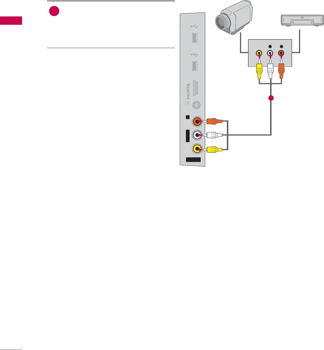
OTHER A/V SOURCE SETUP
AV IN 2
VIDEO
AUDIO
L(MONO)
R
H/P
IN 4
USB IN 1 USB IN 2
L R
VIDEO
Camcorder
Video Game Set
1. How to connect
1Connect the AUDIO/VIDEO jacks
between TV and external equipment.
Match the jack colors
.
(Video = yellow, Audio Left = white, and
Audio Right = red)
2. How to use
ᯫ
Select the AV1 or AV2 input source on
the TV using the INPUT button on the
remote control.
ᯫ
Operate the corresponding external
equipment.
1
45
EXTERNAL EQUIPMENT SETUP
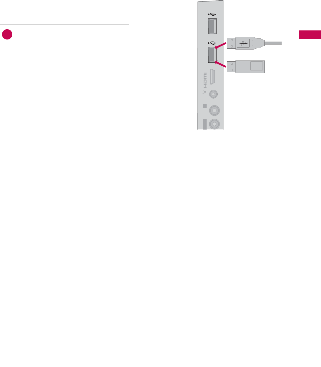
USB CONNECTION
IN 4
AUDIO
L
(MONO)
R
H/P USB IN 1 USB IN 2
Memory Key
or
1. How to connect
1Connect the USB device to the USB
IN 1 or 2 jack on the side of TV.
2. How to use
ᯫ
After connecting the USB IN jack, you
use the USB function. (Źp.93)
EXTERNAL EQUIPMENT SETUP
EXTERNAL EQUIPMENT SETUP
46
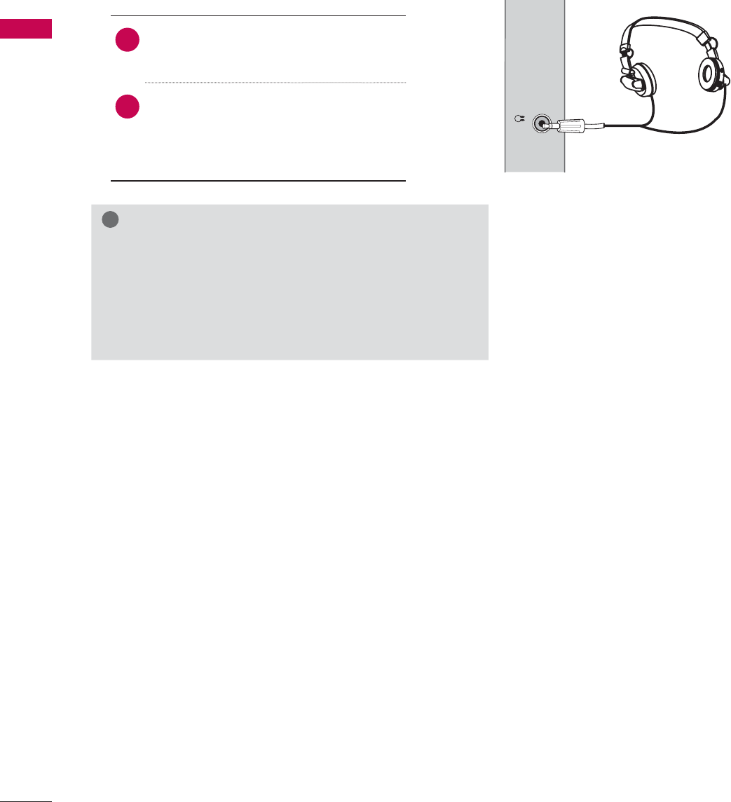
HEADPHONE SETUP (FOR LED LCD TV/LCD TV)
H/P
You can listen to the sound through the headphone.
1. How to connect
1Plug the headphone into the head-
phone socket.
2To adjust the headphone volume,
press the VOL +/- button. If you
press the MUTE button, the sound
from the headphone is switched off.
!
NOTE
ŹAUDIO menu options are disabled when connecting a
headphone.
ŹWhen changing AV MODE with a headphone con-
nected, the change is applied to video but not to audio.
ŹOptical Digital Audio Out is not available when con-
necting a headphone.
47
EXTERNAL EQUIPMENT SETUP
()
L
ESS
T
ROL
(RGB/DVI)
/DVI IN
2
3
1
VIDEO
AUDIO
L(MONO)
R
VIDEO AUDIO
COMPONENT INAV IN 1
AUDIO IN
2
1
AUDIO OUT
YP
B
P
R
L R
OPTICAL DIGITAL
(
)
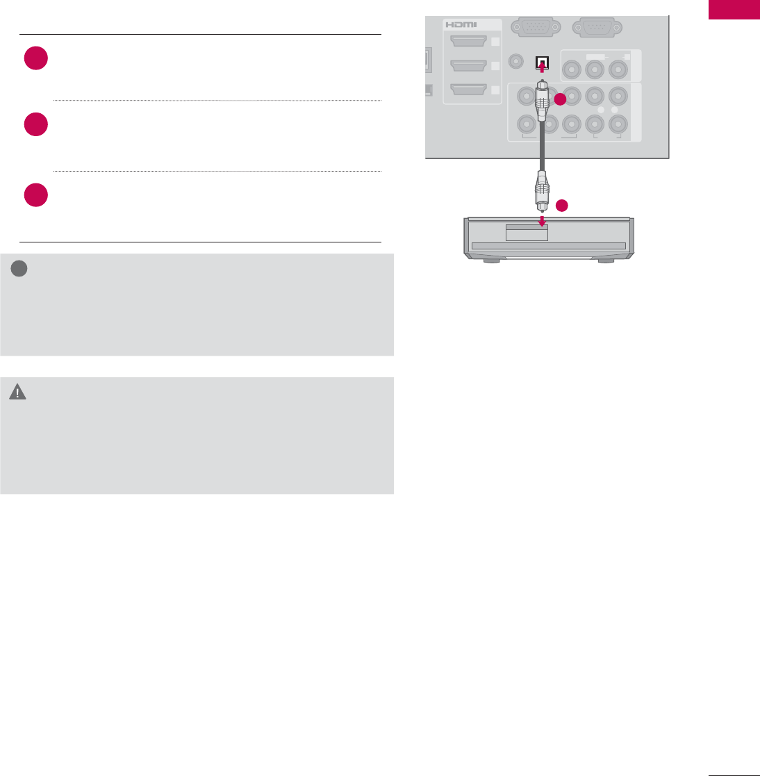
AUDIO OUT CONNECTION
Send the TV’s audio to external audio equipment via the Audio Output port.
If you want to enjoy digital broadcasting through 5.1-channel speakers, connect the OPTICAL DIGITAL
AUDIO OUT terminal on the back of TV to a Home Theater (or amp).
!
NOTE
ŹWhen connecting with external audio equipment, such
as amplifiers or speakers, you can turn the TV speakers
off in the menu. (Źp.150)
CAUTION
ŹDo not look into the optical output port. Looking at
the laser beam may damage your vision.
ŹAudio with ACP (Audio Copy Protection) function may
block digital audio output.
1. How to connect
1Connect one end of the optical cable to the
TV port of OPTICAL DIGITAL AUDIO OUT.
2Connect the other end of the optical cable to
the digital audio input on the audio equip-
ment.
3Set the “TV Speaker option - Off” in the
AUDIO menu. (Źp.150). See the external audio
equipment instruction manual for operation.
1
2
EXTERNAL EQUIPMENT SETUP
EXTERNAL EQUIPMENT SETUP
48
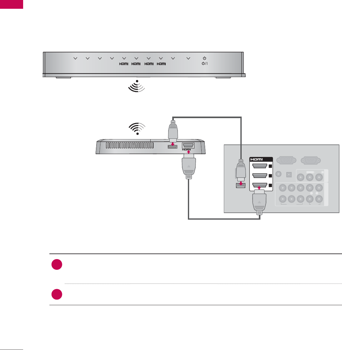
EXTERNAL EQUIPMENT WIRELESS CONNECTION
(OPTIONAL EXTRAS)
LG TVs with a Wireless Control port support the LG Wireless Media Box, which is sold separately.
When you connect the wireless ready dongle (included with the media box) to the TV, external devices
can be connected to the LG Wireless Media Box and video and audio will be sent to the TV wirelessly.
RGB IN (PC)
LAN
(RGB/DVI)
VIDEO
AUDIO
L(MONO)
R
VIDEO AUDIO
COMPONENT INAV IN 1
AUDIO IN
AUDIO OUT
2
1
WIRELESS
CONTROL
OUT
WIRELESS
CONTROL
AV1 AV2
COM1 COM2 1RGB WIRELESS
2 3 4
/DVI IN
2
3
1
YP
B
P
R
L R
OPTICAL DIGITAL
RS-232C IN
(
SERVICE ONLY)
ꔡ
1. How to connect
1Connect the WIRELESS CONTROL jack of the Wireless Ready Dongle to the WIRELESS
CONTROL jack on the TV.
2Connect HDMI OUT jack of the Wireless Ready Dongle to the HDMI IN jack on the TV.
2. How to use
ᯫ
Select the desired input source on the TV using the INPUT button on the remote control.
ᯫ
Refer to the Wireless Media Box manual for operating instructions.
49
EXTERNAL EQUIPMENT SETUP
LAN
IRELESS
O
NTROL
/DVI IN
2
3
1
VIDEO
AUDIO
L(MONO)
R
VIDEO AUDIO
COMPONENT INAV IN 1
AUDIO OUT
2
1
RGB IN (PC)
RGB OUTPUT
AUDIO
(RGB/DVI)
AUDIO IN
YP
B
P
R
L R
OPTICAL DIGITAL
RS-232C IN
(
SERVICE ONLY)
ꔡ
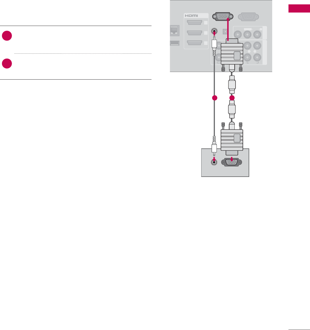
PC SETUP
This TV provides Plug and Play capability, meaning that a PC adjusts automatically to the TV's set-
tings.
1. How to connect
1Connect the VGA output of the PC to the
RGB IN (PC)jack on the TV.
2Connect PC audio output to the AUDIO IN
(RGB/DVI) jack on the TV.
2. How to use
ᯫ
Turn on the PC and the TV.
ᯫ
Select the RGB-PC input source on the TV using
the INPUT button on the remote control.
VGA (D-Sub 15 Pin) Connection
12
EXTERNAL EQUIPMENT SETUP
EXTERNAL EQUIPMENT SETUP
50
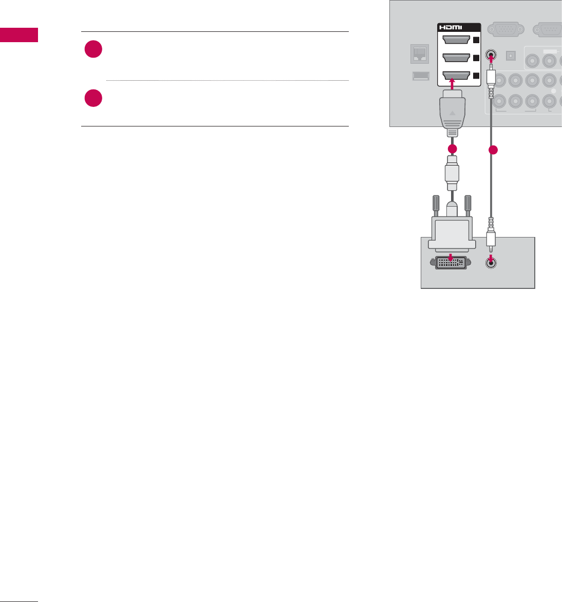
DVI to HDMI Connection
1. How to connect
1Connect the DVI output of the PC to the HDMI/
DVI IN 1,2,3, or 4* jack on the TV.
2Connect the PC audio output to the AUDIO IN
(RGB/DVI) jack on the TV.
2. How to use
ᯫ
Turn on the PC and the TV.
ᯫ
Select the HDMI1,HDMI2,HDMI3, or HDMI4* input
source on the TV using the INPUT button on the
remote control.
DVI OUTPUT AUDIO
RGB IN (PC)
LAN
WIRELESS
CONTROL
VIDEO
AU
L(MONO)
VIDEO AUDI
AUDIO OUT
2
1
/DVI IN
2
3
1
(RGB/DVI)
AUDIO IN
YP
B
P
R
L
OPTICAL DIGITAL
RS-232C IN
(
SERVICE ON
L
ꔡ
12
* HDMI4: For Plasma TV

51
EXTERNAL EQUIPMENT SETUP
Supported Display Specifications (RGB-PC, HDMI-PC)
!
NOTE
ŹTo get the the best picture quality, adjust the PC graphics card to 1920x1080.
ŹDepending on the graphics card, DOS mode may not work if a HDMI to DVI Cable is in use.
ŹIn PC mode, there may be noise associated with the resolution, vertical pattern, contrast or bright-
ness. If noise is present, change the PC output to another resolution, change the refresh rate to
another rate or adjust the brightness and contrast on the PICTURE menu until the picture is clear.
ŹAvoid keeping a fixed image on the screen for a long period of time. The fixed image may become
permanently imprinted on the screen.
ŹThe synchronization input form for Horizontal and Vertical frequencies is separate.
ŹDepending on the graphics card, some resolution settings may not allow the image to be posi-
tioned on the screen properly.
ŹIf you experience overscan issues when using HDMI-PC 1920x1080, change aspect ratio to Just
scan.
ŹWhen selecting HDMI-PC, set the “Input Label - PC” in the OPTION menu.
Resolution Horizontal
Frequency (KHz)Vertical
Frequency (KHz)
640x350 31.468 70.09
720x400 31.469 70.08
640x480 31.469 59.94
800x600 37.879 60.31
1024x768 48.363 60.00
1280x768 47.776 59.87
1360x768
47.712 60.015
1280x1024
63.981 60.02
1920x1080
RGB-PC
66.587 59.934
1920x1080
HDMI-PC
67.50 60.00
EXTERNAL EQUIPMENT SETUP
EXTERNAL EQUIPMENT SETUP
52
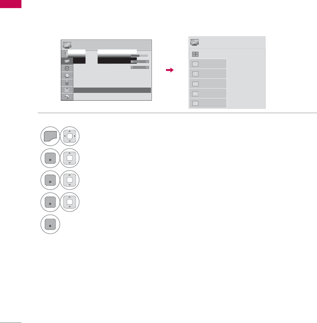
Screen Setup for PC mode
You can choose the resolution in RGB-PC mode.
The Position, Phase, and Size can also be adjusted.
You can choose this option only when the PC resolution is set to 1024X768, 1280X768 or 1360X768.
Selecting Resolution
ᯡ[
۳[
۳[
$XWR&RQILJ
5HVROXWLRQ
3RVLWLRQ
6L]H
Phase
Reset
6&5((1
ᯒ0RYHᰙ3UHY
1
MENU
Select PICTURE.
2
ENTER
Select Screen (RGB-PC).
3
ENTER
Select Resolution.
4
ENTER
Select the desired resolution.
5
ENTER
3,&785( ᯒ0RYHᯙ(QWHU
ᯐ
ᯙ
ؒ&RORU
ؒ7LQW
ؒ&RORU7HPS
ؒ$GYDQFHG&RQWURO
ؒ3LFWXUH5HVHW
ؒ7UX0RWLRQ
ؒ6FUHHQ5*%3&
ؒ/('/RFDO'LPPLQJ2Q
R*
W&
53
EXTERNAL EQUIPMENT SETUP
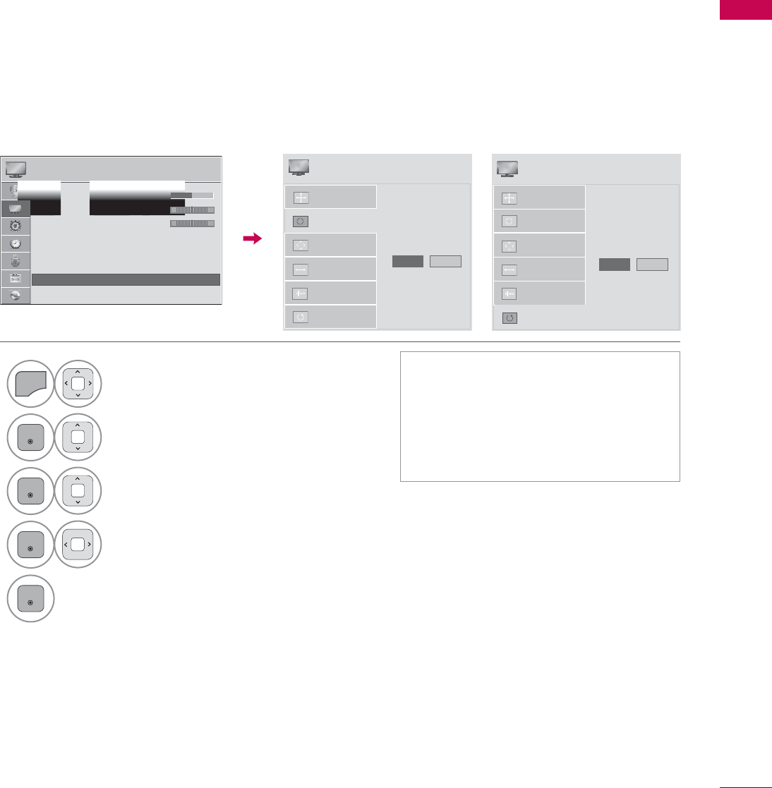
Automatically adjusts picture position and minimizes image instability. After adjustment, if the image
is still not correct, try using the manual settings or a different resolution or refresh rate on the PC.
Auto Configure
1
MENU
Select PICTURE.
2
ENTER
Select Screen (RGB-PC).
3
ENTER
Select Auto Config. or
Reset.
4
ENTER
Select Yes.
5
ENTER
ᯫ
If the position of the image is still not
correct, try Auto adjustment again.
ᯫ
If picture needs to be adjusted again
after Auto adjustment in RGB-PC,
you can adjust the Position,Size or
Phase.
$XWR&RQILJ
5HVROXWLRQ
3RVLWLRQ
6L]H
Phase
Reset
7R6HW
Yes 1R
6&5((1
ᯒ0RYHᰙ3UHY
3,&785( ᯒ0RYHᯙ(QWHU
ᯐ
ᯙ
ؒ&RORU
ؒ7LQW
ؒ&RORU7HPS
ؒ$GYDQFHG&RQWURO
ؒ3LFWXUH5HVHW
ؒ7UX0RWLRQ
ؒ6FUHHQ5*%3&
ؒ/('/RFDO'LPPLQJ2Q
R*
W&
Returns Position,Size, and Phase to the default initial settings.
This feature operates only in RGB-PC mode.
Screen Reset (Reset to original initial values)
$XWR&RQILJ
3RVLWLRQ
5HVROXWLRQ
6L]H
Phase
Reset
7R6HW
Yes 1R
6&5((1
ᯒ0RYHᰙ3UHY
EXTERNAL EQUIPMENT SETUP
EXTERNAL EQUIPMENT SETUP
54
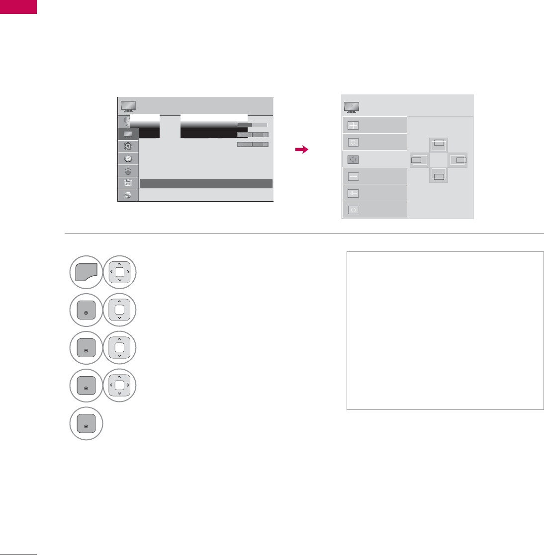
If the picture is not clear after auto adjustment or if text is shaking, adjust the picture phase manually.
This feature operates only in RGB-PC mode.
Adjustment for screen Position, Size, and Phase
1
MENU
Select PICTURE.
2
ENTER
Select Screen (RGB-PC).
3
ENTER
Select Position,Size, or Phase.
4
ENTER
Make appropriate adjustments.
5
ENTER
ᯫ
Position: This function is to adjust
picture to left/right and up/down as
you prefer.
ᯫ
Size: This function is to minimize any
vertical bars or stripes visible on the
screen background. And the horizon-
tal screen size will also change.
ᯫ
Phase: This function allows you to
remove any horizontal noise and
clear or sharpen the image of char-
acters.
Auto Config.
Resolution
Position
Size
Phase
Reset
SCREEN
ᯒ0RYHᰙ3UHY
PICTURE ᯒ0RYHᯙ(QWHU
ᯐ
ᯙ
ؒ&RORU
ؒ7LQW
ؒ&RORU7HPS
ؒ$GYDQFHG&RQWURO
ؒ3LFWXUH5HVHW
ؒ7UX0RWLRQ
ؒ6FUHHQ5*%3&
ؒ/('/RFDO'LPPLQJ2Q
R*
WC
ۻ
܁۽
ۿ
55
EXTERNAL EQUIPMENT SETUP
RGB IN (PC)
WIRELESS
CONTROL
(RGB/DVI)
/DVI IN
2
3
1
VIDEO
AUDIO
L(MONO)
R
VIDEO AUDIO
COMPONENT INAV IN 1
AUDIO IN
AUDIO OUT
2
1
LAN
YP
B
P
R
L R
OPTICAL DIGITAL
RS-232C IN
(
SERVICE ONLY)
ꔡ
Broadband modem
Broadband modem
Router
Broadband Service
Broadband Service
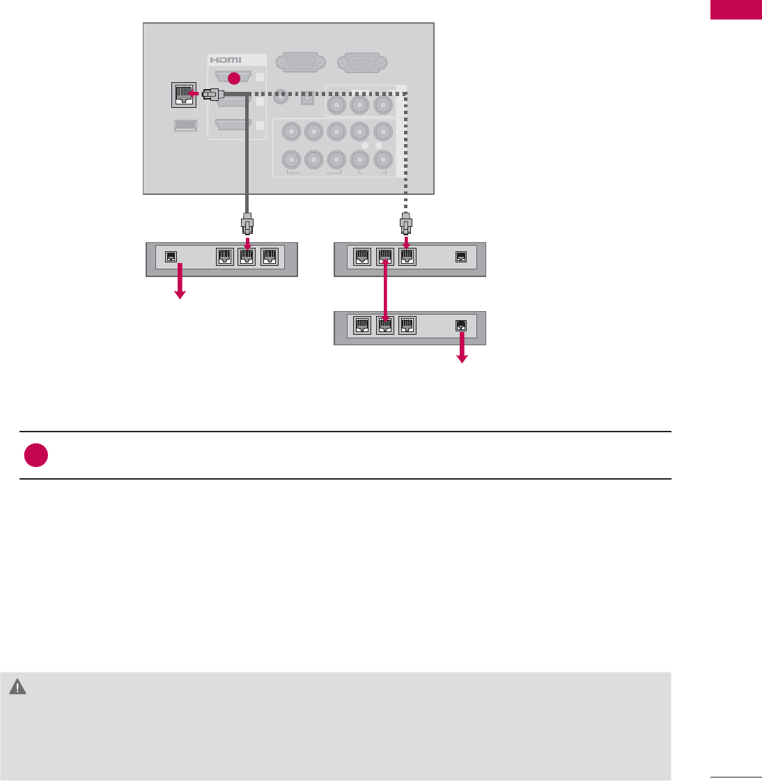
NETWORK SETUP
This TV can be connected to a local area network (LAN) via the LAN port. After making the physical
connection, the TV needs to be set up for network communication.
CAUTION
ŹDo not connect a modular phone cable to the LAN port.
ŹSince there are various connection methods, please follow the specifications of your telecommu-
nication carrier or internet service provider.
1. How to connect
1Connect the LAN port of the Modem or Router to the LAN port on the TV.
2. How to use
ᯫ
Select “Network Setting” in the NETWORK menu.
ᯫ
After connecting the LAN port, use the NETCAST menu.
ᯫ
For more information about NETCAST setup and troubleshooting, visit http://lgknowledgebase.
com. Search for NETCAST.
Wired Network Connection
1
EXTERNAL EQUIPMENT SETUP
EXTERNAL EQUIPMENT SETUP
56
ᯫ
This feature requires an always-on
broadband internet connection.
ᯫ
You do not need to connect to a PC
to use this function.
ᯫ
If Network Setting is not working,
check your network conditions. Check
the LAN cable and make sure your
router has DHCP turned on if you
wish to use the Auto Setting.
ᯫ
If the Network Setting is not com-
pleted, network may not operate nor-
mally.
ᯫ
IP Auto Setting: Select it if there is a
DHCP server on the local area net-
work (LAN) via wired connection, the
TV will automatically be allocated an
IP address. If you’re using a broad-
band router or broadband modem
that has a DHCP (Dynamic Host
Configuration Protocol) server func-
tion. The IP address will automati-
cally be determined.
ᯫ
IP Manual Setting: Select it if there is
no DHCP server on the network and
you want to set the IP address manu-
ally.
1(7:25. ᯒ0RYHᯙ(QWHU
ؒ1HWZRUN6HWWLQJ :LUHG
ؒ1HWZRUN6WDWXV ,QWHUQHWLVFRQQHFWHG
ؒ/HJDO1RWLFH
ؒ(61
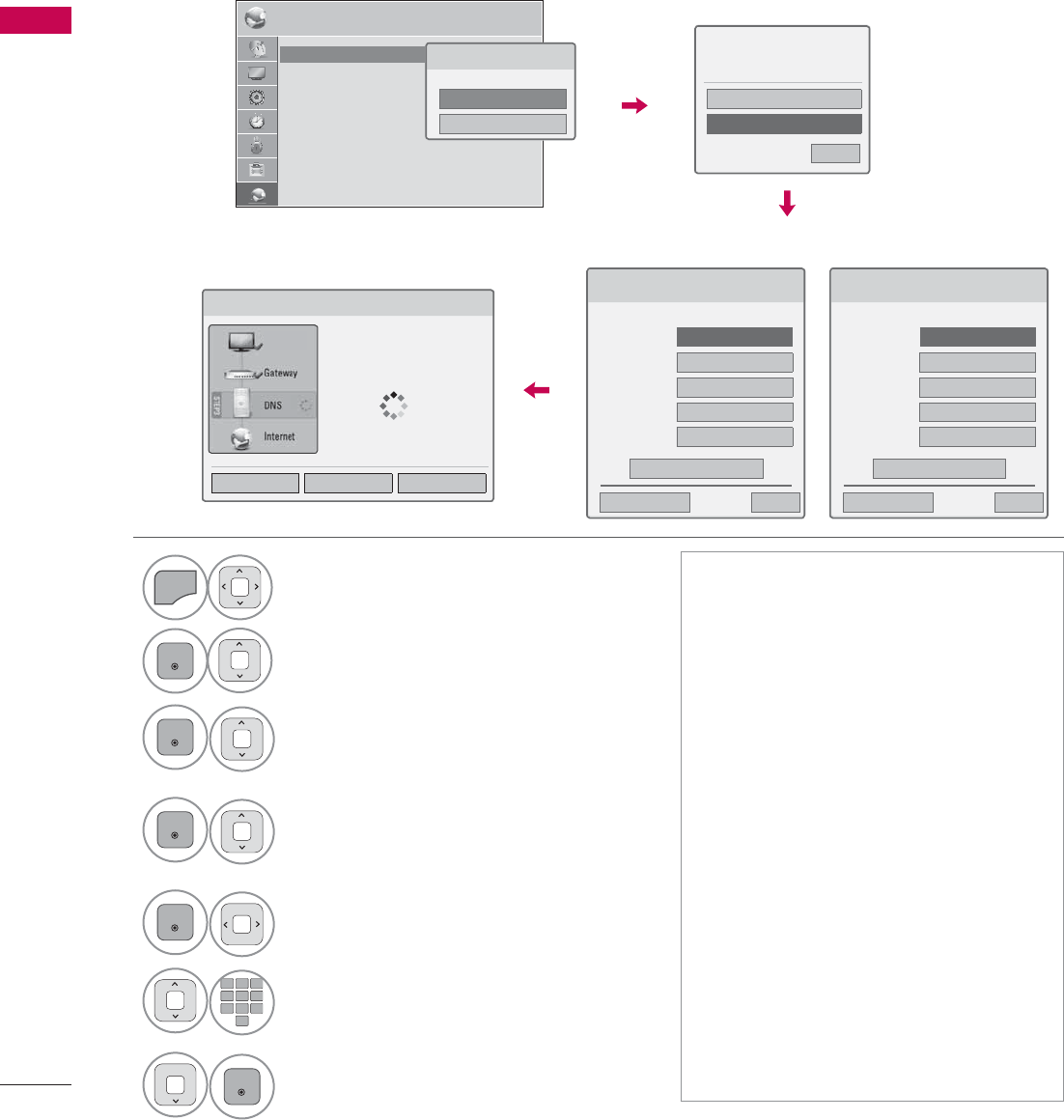
Wired Network Setup
1
MENU
Select NETWORK.
2
ENTER
Select Network Setting.
3
ENTER
Select Wired.
4
ENTER
If you already set Network Setting:
Select Resetting. The new connection
settings resets the current network
settings.
5
ENTER
Select IP Auto Setting or IP Manual
Setting.
12
ABC
3
DEF
4
GHI
5
JKL
6
MNO
7
PQRS
8
TUV
0
9
WXYZ
When Selecting IP Manual Setting:
IP addresses will need to be input
manually.
6
ENTER
Select Enter.
IP Auto Setting
If you already set the
Network Setting
IP Manual Setting
If wired and wireless networks are both available, wired is the preferred method.
After making a physical connection, a small number of home networks may require the TV network
settings to be adjusted.
For detail information, contact your internet provider or router manual.
1HWZRUN7\SH
:LUHGQHWZRUNLVUHFRPPHQGHG
:LUHG
:LUHOHVV
1HWZRUN6HWWLQJ
6HOHFWWKH,3VHWWLQJPRGH
,30RGH ܁,3$XWR6HWWLQJ۽
ᯘ,3$GGUHVV
ᯘ6XEQHW0DVN
ᯘ*DWHZD\
ᯘ'166HUYHU
ᰙ3UHYLRXV
(QWHU
᰿([LW
1HWZRUN6HWWLQJ
,QVHUWWKH,3DGGUHVV
,30RGH ܁,30DQXDO6HWWLQJ۽
ᯘ,3$GGUHVV
ᯘ6XEQHW0DVN
ᯘ*DWHZD\
ᯘ'166HUYHU
ᰙ3UHYLRXV
(QWHU
᰿([LW
1HWZRUN6HWWLQJ
1HWZRUNFRQQHFWLQJ
6HWWLQJ 7HVW &ORVH
3UHYLRXVVHWWLQJYDOXHH[LVWV'R
\RXZDQWWRFRQQHFWZLWKWKH
SUHYLRXVVHWWLQJ"
(QWHU
5HVHWWLQJ
᰿([LW
ᯙ1H[W
79

57
EXTERNAL EQUIPMENT SETUP
!
NOTE
ŹFor more information about NETCAST setup
and troubleshooting, visit http://lgknowledge-
base.com. Search for NETCAST.
ŹUse a standard LAN cable with this TV. Cat5
or better with a RJ45 connector.
ŹMany network connection problems during set
up can often be fixed by re-setting the router
or modem. After connecting the player to the
home network, quickly power off and/or dis-
connect the power cable of the home network
router or cable modem. Then power on and/or
connect the power cable again.
ŹDepending on the internet service provider
(ISP), the number of devices that can receive
internet service may be limited by the appli-
cable terms of service. For details, contact
your ISP.
ŹLG is not responsible for any malfunction of
the TV and/or the internet connection feature
due to communication errors/malfunctions
associated with your broadband internet con-
nection, or other connected equipment.
ŹLG is not responsible for problems within your
internet connection.
ŹSome content available through the network
connection may not be compatible with the
TV. If you have questions about such content,
please contact the producer of the content.
ŹYou may experience undesired results if the
network connection speed does not meet the
requirements of the content being accessed.
ŹSome internet connection operations may not
be possible due to certain restrictions set by
the Internet service provider (ISP) supplying
your broadband Internet connection.
ŹAny fees charged by an ISP including, without
limitation, connection charges are your respon-
sibility.
ŹA 10 Base-T or 100 Base-TX LAN port is
required for connection to this TV. If your inter-
net service does not allow for such a connec-
tion, you will not be able to connect the TV.
ŹA DSL modem is required to use DSL service
and a cable modem is required to use cable
modem service. Depending on the access
method of and subscriber agreement with
your ISP, you may not be able to use the inter-
net connection feature contained in this TV or
you may be limited to the number of devices
you can connect at the same time. (If your ISP
limits subscription to one device, this TV may
not be allowed to connect when a PC is
already connected.)
ŹThe use of a “Router” may not be allowed or
its usage may be limited depending on the
policies and restrictions of your ISP. For details,
contact your ISP directly.
ŹThe wireless network operates at 2.4 GHz
radio frequencies that are also used by other
household devices such as cordless tele-
phone, Bluetooth® devices, microwave oven,
and can be affected by interference from
them. It can be interrupted by the device
using 5Ghz radio frequencies. It is same
device with LG wireless media box, cordless
telephone, other Wi-Fi device.
ŹIt may decrease the service speed using
Wireless network by surrounding wireless con-
dition.
ŹTurn off all unused network equipment in your
local home network. Some devices may gen-
erate network traffic.
ŹIn some instances, placing the access point or
wireless router higher up away from the floor
may improve the reception.
ŹThe reception quality over wireless depends
on many factors such as type of the access
point, distance between the TV and access
point, and the location of the TV.
ŹWhen connecting internet through the wired/
wireless sharing machine, it may interrupt the
connection because of the use limitation and
confirmation of service company.
EXTERNAL EQUIPMENT SETUP
EXTERNAL EQUIPMENT SETUP
58
IN 4
AV IN 2
VIDEO
AUDIO
L(MONO)
R
H/P USB IN 1 USB IN 2
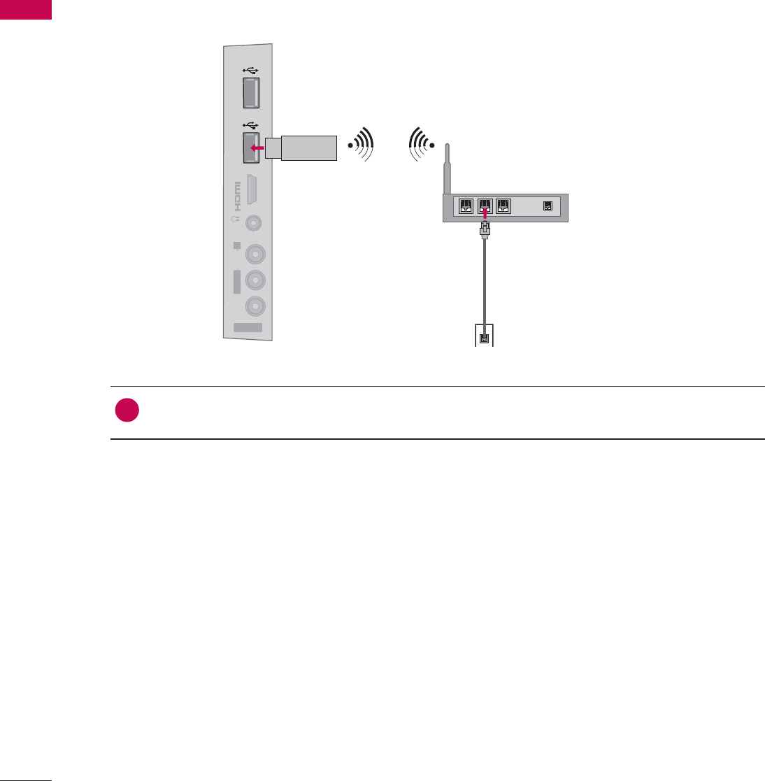
The LG Wireless LAN for Broadband/DLNA Adaptor, which is sold separately, allows the TV to connect
to a wireless lan network.
The network configuration and connection method may vary depending on the equipment in use and
the network environment. Refer to the setup instructions supplied with your access point or wireless
router for detailed connection steps and network settings.
1. How to connect
1Connect the “LG Wireless LAN for Broadband/DLNA Adaptor (sold separately)” to the USB
IN 1 or 2port on the TV.
2. How to use
ᯫ
Select “Network Setting” in the NETWORK menu.
ᯫ
After connecting, you can use the NETCAST menu.
Wireless Network
59
EXTERNAL EQUIPMENT SETUP
Setting up the AP (Access Point) or the wireless router is required before connecting the TV to the
network.
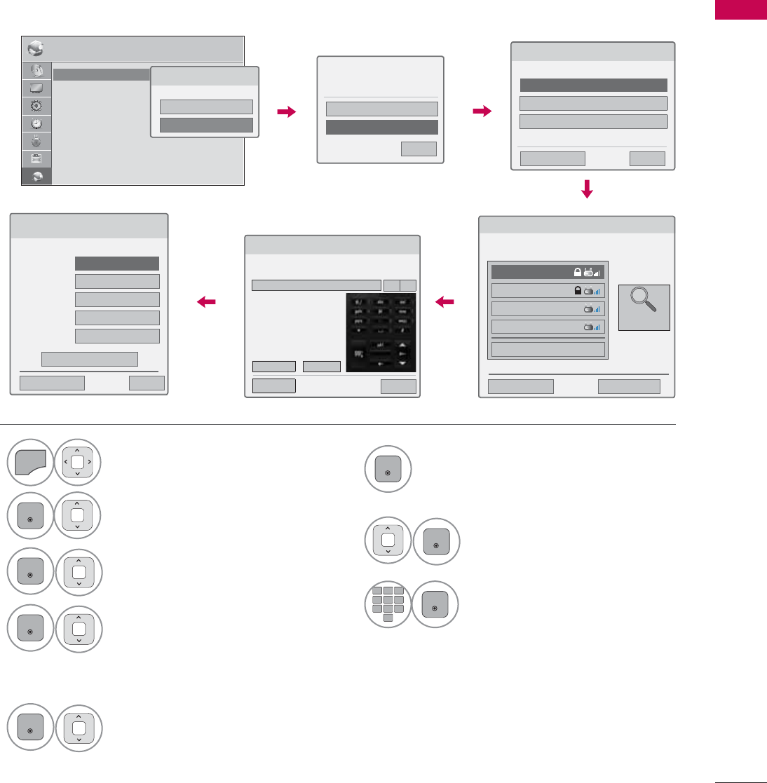
Wireless Network Setup
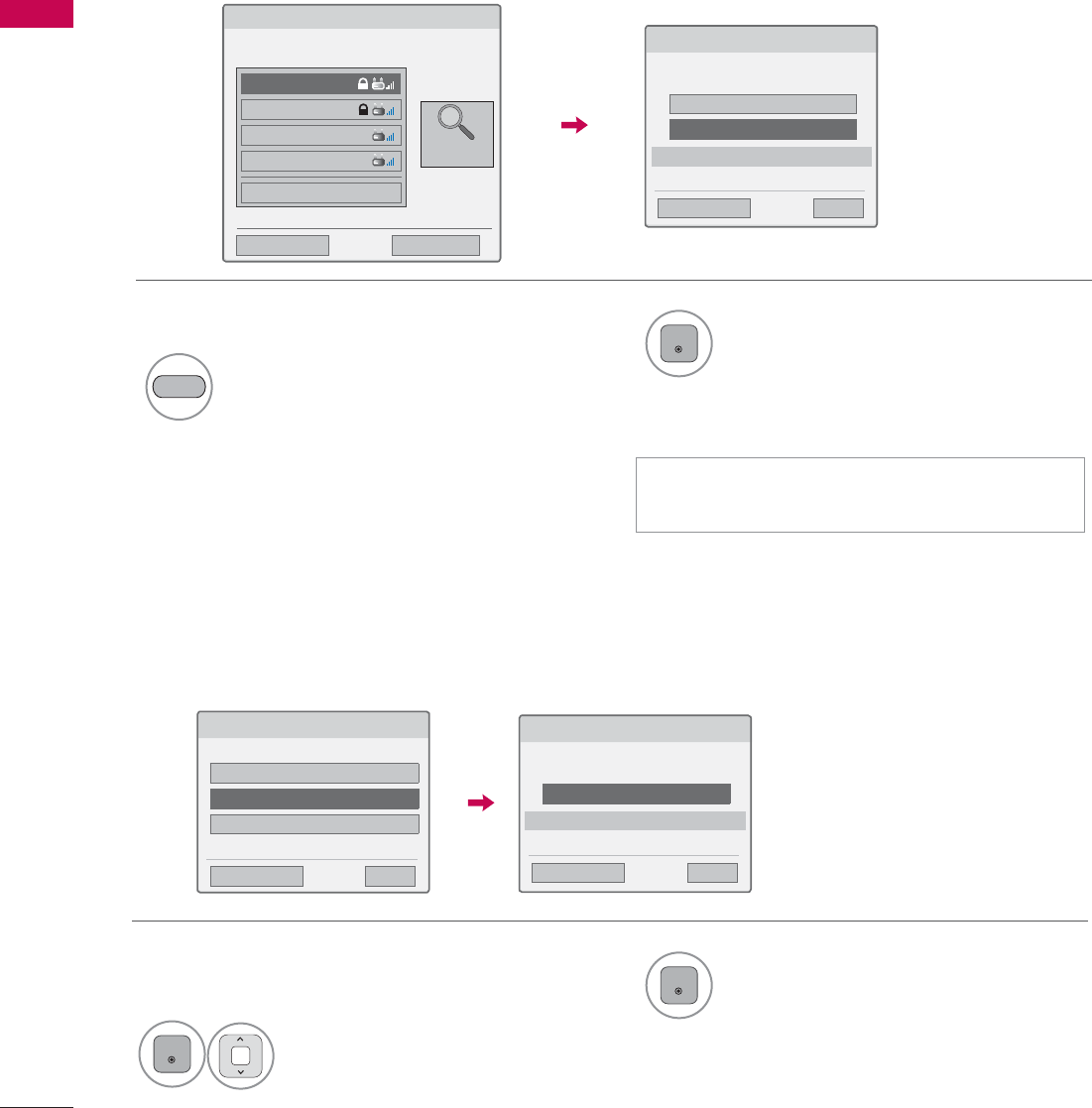
6
ENTER
Scan the all available AP (Access
Point) or wireless routers within range
and display them as a list.
7
ENTER
Select an AP (Access Point) or
wireless router on the list.
(If your AP is locked, insert the
security key of AP).
8
12
ABC
3
DEF
4
GHI
5
JKL
6
MNO
7
PQRS
8
TUV
0
9
WXYZ
ENTER
Input the security key of AP.
1
MENU
Select NETWORK.
2
ENTER
Select Network Setting.
3
ENTER
Select Wireless.
4
ENTER
If you already set Network
Setting: Select Resetting.
The new connection settings
resets the current network set-
tings.
5
ENTER
Select Setting from the AP list.
1(7:25. ᯒ0RYHᯙ(QWHU
ؒ1HWZRUN6HWWLQJ :LUHG
ؒ1HWZRUN6WDWXV ,QWHUQHWLVFRQQHFWHG
ؒ/HJDO1RWLFH
ؒ(61
1HWZRUN7\SH
:LUHGQHWZRUNLVUHFRPPHQGHG
:LUHG
:LUHOHVV
6HOHFWLQJWKHZLUHOHVVQHWZRUNVHWWLQJW\SH
6HOHFWWKHZLUHOHVVQHWZRUNVHWWLQJW\SH
6HWWLQJIURPWKH$3OLVW
6LPSOHVHWWLQJ3%&0RGH
6HWWLQJ$GKRFQHWZRUN
ᰙ3UHYLRXV ᰿([LW
ᯙ1H[W
6HOHFWLQJ$3
ᰙ3UHYLRXV ᰿([LW
ᯙ1H[W
6HOHFW$3\RXZDQWWRFRQQHFW
PDJH1/1
,37,0(
LSWLPH
ASW
1HWZRUN
ᯕ&RQQHFWLQJZLWK3,1PRGH
$FFHVV3RLQW
6HDUFK
9Repeat step 4-5 on P.56.
If your AP is locked
If you already set the
Network Setting
3UHYLRXVVHWWLQJYDOXHH[LVWV'R
\RXZDQWWRFRQQHFWZLWKWKH
SUHYLRXVVHWWLQJ"
(QWHU
5HVHWWLQJ
᰿([LW
ᯙ1H[W
,QVHUWLQJWKHVHFXULW\NH\
,QVHUWWKHVHFXULW\NH\RI$3
,QVHUWKH[DGHFLPDOa$a)RUGLJLWV,QVHUWRU$6&,,FKDUDFWHUV
(QWHU &DQFHO
ᰙ3UHY ᰿([LW
܁۽
1HWZRUN6HWWLQJ
6HOHFWWKH,3VHWWLQJPRGH
,30RGH ܁,3$XWR6HWWLQJ۽
ᯘ,3$GGUHVV
ᯘ6XEQHW0DVN
ᯘ*DWHZD\
ᯘ'166HUYHU
ᰙ3UHYLRXV
(QWHU
᰿([LW
EXTERNAL EQUIPMENT SETUP
EXTERNAL EQUIPMENT SETUP
60
If you want to connect the AP (Access Point) or router with PIN, use this feature.
If your access point or wireless router that supports PIN or PBC, it’s available to use your access point
or wireless router within 120 counts. You do not need to know the access point name (SSID: Service
Set Identifier) and security code of your access point or wireless router.
When a security code is already set
PIN (Personal Identification Number)
PBC (Push Button Configuration)
ᯫ
PIN number is the unique 8 digit number
of the dongle.
&RQQHFWLQJZLWK3,1PRGH
,QVHUW3,1QXPEHUDWWKH$3ZHESDJHDQG
SUHVV؋&RQQHFW،EXWWRQ
3,118%0(5
&RQQHFW
ᰙ3UHYLRXV
)RUPRUHLQIRUPDWLRQFKHFNWKH$3PDQXDO
᰿([LW
ᯙ1H[W
6LPSOHVHWWLQJ3%&0RGH
3UHVV3%&0RGHEXWWRQRI$3DQGSUHVV؋&RQQHFW،EXWWRQ
&RQQHFW
ᰙ3UHYLRXV
&DXWLRQ&KHFNLI3%&PRGHEXWWRQLVDYDLODEOHIRU\RXU$3
᰿([LW
ᯙ1H[W
6HOHFWLQJ$3
ᰙ3UHYLRXV ᰿([LW
ᯙ1H[W
6HOHFW$3\RXZDQWWRFRQQHFW
PDJH1/1
,37,0(
LSWLPH
ASW
1HWZRUN
ᯕ&RQQHFWLQJZLWK3,1PRGH
$FFHVV3RLQW
6HDUFK
2Connect the acccess point with PIN
mode.
4
ENTER
Select Connect.
RED
1Repeat step 1-7 on P.59.
3You can see the Network ID and Security Key
on your TV screen.
Enter the PIN number to your device.
6HOHFWWKHZLUHOHVVQHWZRUNVHWWLQJW\SH
6HOHFWWKHZLUHOHVVQHWZRUNVHWWLQJW\SH
6HWWLQJIURPWKH$3OLVW
6LPSOHVHWWLQJ3%&0RGH
6HWWLQJ$GKRFQHWZRUN
ᰙ3UHYLRXV ᰿([LW
ᯙ1H[W
1Repeat step 1-4 on P.59. 3
ENTER
Select Connect.
2
ENTER
Select Simple setting (PBC
mode).
5Repeat step 4-5 on P.56.
4Repeat step 4-5 on P.56.
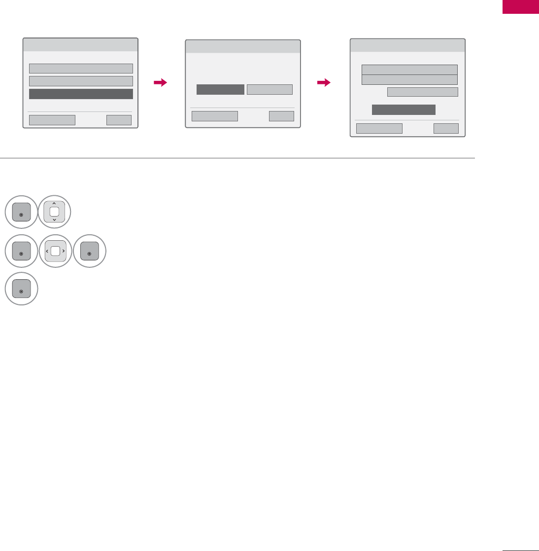
61
EXTERNAL EQUIPMENT SETUP
This is the method of communicating directly with the machine to communicate without AP.
This is the same as connecting two PCs with a cross cable.
AD-hoc Mode
1Repeat step 1-3 on P.59.
6HOHFWLQJWKHZLUHOHVVQHWZRUNVHWWLQJW\SH
6HOHFWWKHZLUHOHVVQHWZRUNVHWWLQJW\SH
6HWWLQJIURPWKH$3OLVW
6LPSOHVHWWLQJ3%&0RGH
6HWWLQJ$GKRFQHWZRUN
ᰙ3UHYLRXV ᰿([LW
ᯙ1H[W
6HWWLQJ$GKRFQHWZRUN
)HDWXUHVXVLQJH[LWLQJQHWZRUNFDQEHXQDYDLODEOH'R\RX
ZDQWWRFKDQJHQHWZRUNFRQQHFWLRQ"
ᰙ3UHYLRXV ᰿([LW
ᯙ1H[W
(QWHU &DQFHO
6HWWLQJ$GKRFQHWZRUN
,QVHUWWKHVHWWLQJLQIRUPDWLRQLQWRWKHGHYLFH
ᰙ3UHYLRXV ᰿([LW
ᯙ1H[W
1HWZRUN,'66,'/*79
6HFXULW\.H\
ᯕ&KDQJLQJWKHVHWWLQJLQIRUPDWLRQ
&RQQHFW
2
ENTER
Select Setting AD-hoc network.
3
ENTER
ENTER
Select Enter.
4
ENTER
Select Connect to connect Ad-hoc network.
You can see the Network ID and Security Key
on your TV screen.
Enter this Network ID and Security Key to
your device.
If a network may not operate, change the
setting information using the RED button.
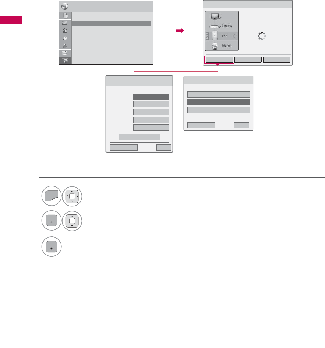
EXTERNAL EQUIPMENT SETUP
EXTERNAL EQUIPMENT SETUP
62
1
MENU
Select NETWORK.
2
ENTER
Select Network Status.
3
ENTER
Check the newtwork status.
Network Status
1HWZRUN6HWWLQJ
1HWZRUNFRQQHFWLQJ
6HWWLQJ 7HVW &ORVH
ᯫ
Setting: Return to the network set-
ting menu or wireless network setting
type menu.
ᯫ
Test: Test the current network status
after setting the network.
ᯫ
Close: Return to the previous menu.
1(7:25. ᯒ0RYHᯙ(QWHU
ؒ1HWZRUN6HWWLQJ :LUHG
ؒ1HWZRUN6WDWXV ,QWHUQHWLVFRQQHFWHG
ؒ/HJDO1RWLFH
ؒ(61
6HOHFWWKHZLUHOHVVQHWZRUNVHWWLQJW\SH
6HOHFWWKHZLUHOHVVQHWZRUNVHWWLQJW\SH
6HWWLQJIURPWKH$3OLVW
6LPSOHVHWWLQJ3%&PRGH
6HWWLQJ$GKRFQHWZRUN
ᰙ3UHYLRXV ᰿([LW
ᯙ1H[W
Wired Connection
Wireless Connection
1HWZRUN6HWWLQJ
6HOHFWWKH,3VHWWLQJPRGH
,30RGH ܁,3$XWR6HWWLQJ۽
ᯘ,3$GGUHVV
ᯘ6XEQHW0DVN
ᯘ*DWHZD\
ᯘ'166HUYHU
ᰙ3UHYLRXV
(QWHU
᰿([LW
79
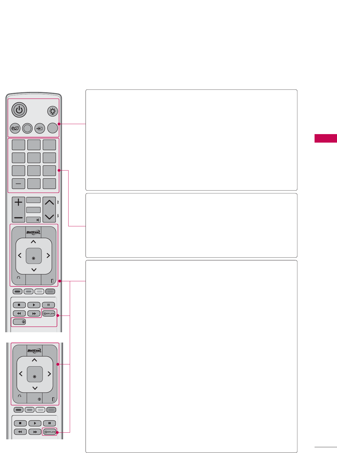
63
WATCHING TV / CHANNEL CONTROL
ENERGY
CHVOL
12 ABC 3 DEF
4 GHI 5 JKL 6
MNO
7
PQRS
8 TUV
0
9
WXYZ
P
A
G
E
SAVING
TV
AV MODE
INPUT
LIGHT
FAV
RATIO
MUTE
BACK
WIDGETS
EXIT
ENTER
MARK
DELETE
CHAR/NUM
LIST
FLASHBK
MENU
FREEZE
Q.MENU
INFO
BACK EXIT
ENTER
MENU
Q.MENU
INFO
FREEZE
REMOTE CONTROL FUNCTIONS
When using the remote control, aim it at the remote control sensor on the TV.
The remote control may differ from the images below.
WATCHING TV / CHANNEL CONTROL
POWER Turns the TV on from standby or off to standby.
LIGHT Illuminates the remote control buttons.
(Except 32/42/46/52/60LD550, 47/55LD650)
ENERGY SAVING
Adjusts the Energy Saving setting. Źp.132
AV MODE Toggles through preset Video and Audio modes. Źp.88
INPUT Rotates through inputs.
Also switches the TV on from standby. Źp.83
TV Returns to the last TV channel.
NUMBER button
— (DASH) Used to enter a program number for multiple program
channels such as 2-1, 2-2, etc.
LIST Displays the channel table. Źp.80
FLASHBK Tunes to the last channel viewed.
MENU Displays the main menu or clears all on-screen displays
and return to TV viewing.
NETCAST
Select the desired NETCAST menu source.
Źp.123
Q.MENU Opens the list of Quick Menu options. Źp.71
THUMBSTICK
(Up/Down/Left
Right/ENTER)
Navigates the on-screen menus and adjusts the system
settings to your preference.
BACK Allows the user to move return one step in an interactive
application or other user interaction function.
WIDGETS WIDGETS for showing or hiding the Yahoo! Dock and
accessing the Yahoo! TV Widgets user experience.
INFO Displays channel information at the bottom of the
screen. Źp.81
EXIT Clears all on-screen displays and return to TV viewing.
SIMPLINK See a list of AV devices connected to TV.
When you toggle this button, the SIMPLINK menu
appears at the screen. Źp.90
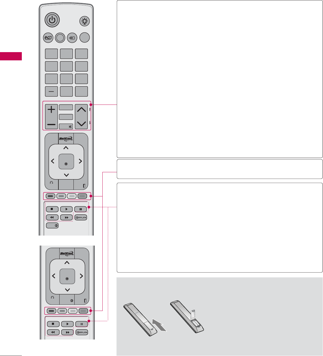
WATCHING TV / CHANNEL CONTROL
WATCHING TV / CHANNEL CONTROL
64
ᯫ
Open the battery compartment cover
on the back side and install the batter-
ies matching correct polarity.
ᯫ
Install two 1.5V AAA batteries. Don’t
mix old or used batteries with new
ones.
ᯫ
Close cover.
Installing Batteries
ENERGY
CHVOL
12 ABC 3 DEF
4 GHI 5 JKL 6
MNO
7
PQRS
8 TUV
0
9
WXYZ
P
A
G
E
SAVING
TV
AV MODE
INPUT
LIGHT
FAV
RATIO
MUTE
BACK
WIDGETS
EXIT
ENTER
MARK
DELETE
CHAR/NUM
LIST
FLASHBK
MENU
FREEZE
Q.MENU
INFO
BACK EXIT
ENTER
MENU
Q.MENU
INFO
FREEZE
VOLUME
UP/DOWN Adjusts the volume.
FAV Set up desired favorite channels list. Źp.79
MARK Select the input to apply the Picture Wizard settings.
Źp.131
Use to mark or unmark a photo/music/movie. Źp.105,
110, 116
RATIO Changes the aspect ratio. Źp.128
CHAR/NUM Shifts the Character or Number for internet service.
MUTE Switches the sound on or off. Źp.66
DELETE Deleted the character or number on the screen.
CHANNEL
UP/DOWN
Changes the channel.
PAGE
UP/DOWN
Moves from one full set of screen information to the
next one.
COLOR
BUTTON
Access special functions in some menus.
USB,
SIMPLINK
Control buttons
ţControls MY MEDIA menu (Movie List, Photo List,
Music List)
ţ Controls the SIMPLINK compatible devices.
FREEZE
(For Plasma TV)
Pause the present picture at the screen. (It doesn’t work
at USB Mode and Simplink.)
The TV returns to normal viewing automatically if no
signal is received or no operation is performed for 5
minutes.
If you keep the screen in Freeze condition, the residu-
al image can exist.
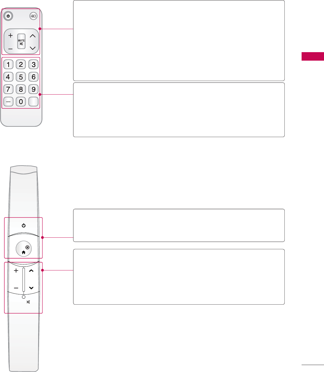
65
WATCHING TV / CHANNEL CONTROL
Simple Remote Control (For 42/47/55LE7500, 47/55LE8500)
Motion Remote Control (For 50/60PK950)
CH
FLASHBK
VOL
POWER TV/INPUT
POWER Turns the TV on from standby or off to standby.
TV/INPUT Rotates through inputs.
Also switches the TV on from standby. Źp.83
VOLUME UP/
DOWN Adjusts the volume.
MUTE Switches the sound on or off. Źp.66
CHANNEL
UP/DOWN
Changes the channel.
NUMBER button
— (DASH) Used to enter a program number for multiple program
channels such as 2-1, 2-2, etc.
FLASHBK Tunes to the last channel viewed.
ENTER
VOL
MUTE
CH
POWER Turns the TV on from standby or off to standby.
ENTER
VOLUME UP/
DOWN Adjusts the volume.
CHANNEL
UP/DOWN
Changes the channel.
MUTE Switches the sound on or off. Źp.66

WATCHING TV / CHANNEL CONTROL
WATCHING TV / CHANNEL CONTROL
66
TURNING ON THE TV
CHANNEL SELECTION
VOLUME ADJUSTMENT
Adjust the volume to suit your personal preference.
1First, connect power cord correctly.
At this moment, the TV switches to standby mode.
ᯫ
In standby mode to turn TV on, press the / I,INPUT,CH (ᰜor ᰝ) button on the TV or press
the , INPUT, CH (ᰜor ᰝ),Number (0-9) button on the remote control.
2Select the viewing source by using the INPUT button on the remote control.
3When finished using the TV, press the POWER button on the remote control. The TV reverts
to standby mode.
!
NOTE
Ź If you intend to be away on vacation, disconnect the power plug from the wall power outlet.
Ź If you do not complete the Initial setting, it will appear whenever the TV is switched on until the
Initial setting procedure is completed.
1Press the CH (ᰜor ᰝ) or NUMBER buttons to select a channel number.
1 Press the VOL (+ or -) button to adjust the volume.
2If you want to switch the sound off, press the MUTE button.
3You can cancel the Mute function by pressing the MUTE or VOL (+ or -) button.
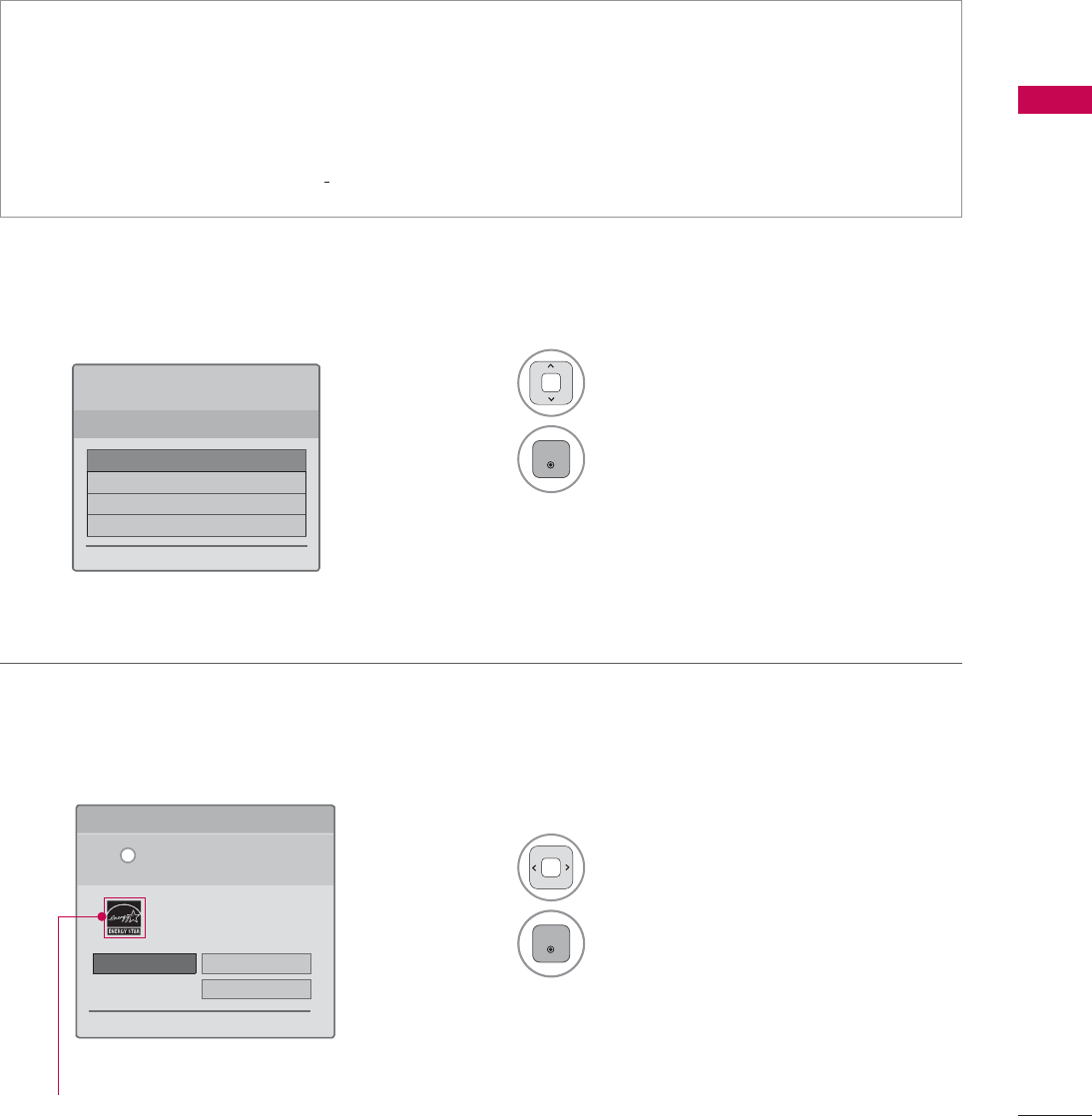
67
WATCHING TV / CHANNEL CONTROL
Step 1. Selecting Language
Step 2. Mode setting
INITIAL SETTING
This Function guides the user to easily set the essential items for viewing the TV for the first time
when purchasing the TV. It will be displayed on the screen when turning the TV on for the first time. It
can also be activated from the user menus.
ᯫ
Default selection is “Home Use”. We recommend setting the TV to “Home Use” mode for the best
picture in your home environment.
ᯫ
“Store Demo” Mode is only intended for use in retail environments. Customers can adjust the
“Picture menu - Picture mode” manually while inspecting the TV, but the TV will automatically
return to preset in-store mode after 5 minutes.
ᯫ
“Store Demo” Mode is an optimal setting for displaying at stores. “Store Demo” mode initializes
the TV to set the image quality.
1Select Menu Language.
2
ENTER
1Select Home Use.
2
ENTER
6WHS0RGH6HWWLQJ
6HOHFWLQJWKHHQYLURQPHQW
&KRRVHWKHVHWWLQJPRGH\RXZDQW
6HOHFW>+RPH8VH@ZKHQVHWWLQJ79XS
LQKRPH<RXFDQDGMXVWSLFWXUHTXDOLW\
DFFRUGLQJO\WKURXJK3LFWXUH0RGHPHQX
RSWLRQ
ᰙ3UHYLRXV ᯙ1H[W
:(/&20(
7KDQN\RXIRUFKRRVLQJ/*
ᯙ1H[W
6WHS/DQJXDJH
(QJOLVK
(VSDñol
)UDQ«DLV
䭢⍴㮻
L
+RPH8VH 6WRUH'HPR
ؒ'HPR0RGH 2II
For LED LCD TV
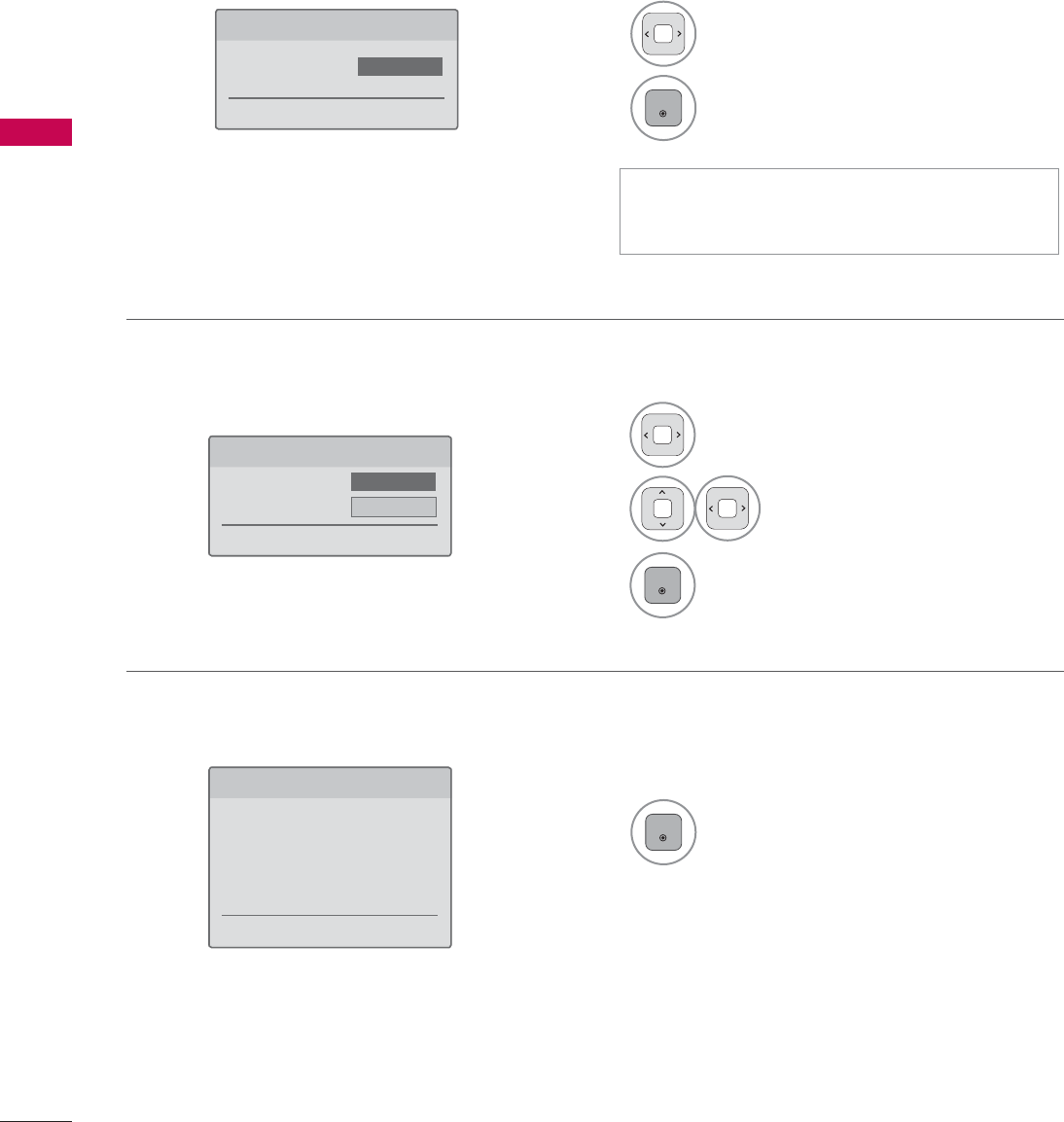
WATCHING TV / CHANNEL CONTROL
WATCHING TV / CHANNEL CONTROL
68
Step 4. Time Zone
Step 5. Auto Tuning
1Select Time Zone option.
2Select Daylight Saving
option.
3
ENTER
1
ENTER
Check your antenna connection and
start Auto Tuning.
6WHS7LPH=RQH
ᰙ3UHYLRXV ᯙ1H[W
7LPH=RQH ܁(DVWHUQ۽
'D\OLJKW6DYLQJ Auto
6WHS$XWR7XQLQJ
ᰙ3UHYLRXV ᯙ1H[W
%HIRUHVWDUWLQJ
EHVXUHWKDWWKH
79DQWHQQDLVFRQQHFWHG
Step 3. Power Indicator (For LED LCD TV)
1Select On or Off.
2
ENTER
6WHS3RZHU,QGLFDWRU
ᰙ3UHYLRXV ᯙ1H[W
6WDQGE\/LJKW ܁2II۽
ᯫ
This function is disable in “Step2. Mode
Setting - Store Demo”.
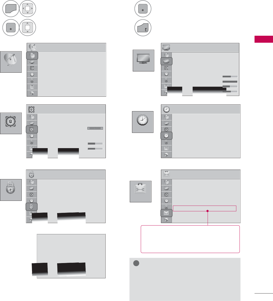
69
WATCHING TV / CHANNEL CONTROL
&+$11(/
237,21
3,&785(
$8',2 7,0(
/2&.
ON-SCREEN MENUS SELECTION
Your TV's OSD (On Screen Display) may differ slightly from that shown in this manual.
3,&785( ᯒ0RYHᯙ(QWHU
ؒ$VSHFW5DWLR
ؒ3LFWXUH:L]DUG
ؒ ᰚ(QHUJ\6DYLQJ 2II
ؒ3LFWXUH0RGH 6WDQGDUG
ؒ%DFNOLJKW
ؒ&RQWUDVW
ؒ%ULJKWQHVV
ؒ6KDUSQHVV
7,0( ᯒ0RYHᯙ(QWHU
ؒ&ORFN
ؒ2II7LPH 2II
ؒ2Q7,PH 2II
ؒ6OHHS7LPHU 2II
/2&. ᯒ0RYHᯙ(QWHU
ؒ6HW3DVVZRUG
ؒ/RFN6\VWHP 2Q
ؒ%ORFN&KDQQHO
ؒ0RYLH5DWLQJ
ؒ795DWLQJ&KLOGUHQ
ؒ795DWLQJ*HQHUDO
ؒ'RZQORDGDEOH5DWLQJ
ؒ,QSXW%ORFN
ؒ6HW3DVVZRUG
ؒ/RFN6\VWHP 2Q
ؒ%ORFN&KDQQHO
ؒ795DWLQJ(QJOLVK
ؒ795DWLQJ)UHQFK
ؒ'RZQORDGDEOH5DWLQJ
ؒ,QSXW%ORFN
ؒ.H\/RFN 2II
237,21 ᯒ0RYHᯙ(QWHU
ؒ/DQJXDJH
ؒ&DSWLRQ 2II
ؒ3RZHU,QGLFDWRU
ؒ,QLWLDO6HWWLQJ
ؒ0RGH6HWWLQJ +RPH8VH
ؒ,5%ODVWHU 2II
$8',2 ᯒ0RYHᯙ(QWHU
ؒ$XWR9ROXPH 2II
ؒ&OHDU9RLFH,, 2IIᰕ3
ؒ%DODQFH
ؒ6RXQG0RGH 6WDQGDUG
ؒ
,QILQLWH6RXQG2II
ؒ7UHEOH
ؒ%DVV
ؒ5HVHW
/R
&+$11(/ ᯒ0RYHᯙ(QWHU
ؒ$XWR7XQLQJ
ؒ0DQXDO7XQLQJ
ؒ&KDQQHO(GLW
1
MENU
Display each menu.
2
ENTER
Select a menu item.
3
ENTER
Accept the current selection.
4
EXIT
Return to TV viewing.
!
NOTE
ŹISM Method: For Plasma TV.
ŹBacklight, TruMotion, LED Local Dimming,
Power Indicator: For LED LCD TV/LCD
TV.
ᯫ
For further information, refer to the
optional “Wireless Media Box”
manual for operating instructions.
For USA
For Canada

WATCHING TV / CHANNEL CONTROL
WATCHING TV / CHANNEL CONTROL
70
,1387
0<0(',$
*$0(
,QSXW/LVW ᯒ0RYH ᯙ(QWHU
79 86% 86% $9 $9 &RPSRQHQW
&RPSRQHQW 5*%3& +'0, +'0, +'0, +'0,
ᯕ,QSXW/DEHO ᰙ([LW
0RYLH/LVW
0<0(',$
3UHVV(QWHUᯙWRVHHPRYLHVIURPWKH86%
ᯕ2SWLRQ ᰙ([LW
3KRWR/LVW 0XVLF/LVW
1(7:25.
1(7:25. ᯒ0RYHᯙ(QWHU
ؒ1HWZRUN6HWWLQJ 1RQH
ؒ1HWZRUN6WDWXV 1RWFRQQHFWHG
ؒ/HJDO1RWLFH
ؒ(61
-803 +2/(,121( :+$&.$02/( 68'2.8 &22.,1*%85*(5
6$9,1*&5<67$/ ,19$'(5 85*(176859,9$/
᰿([LW
*$0(
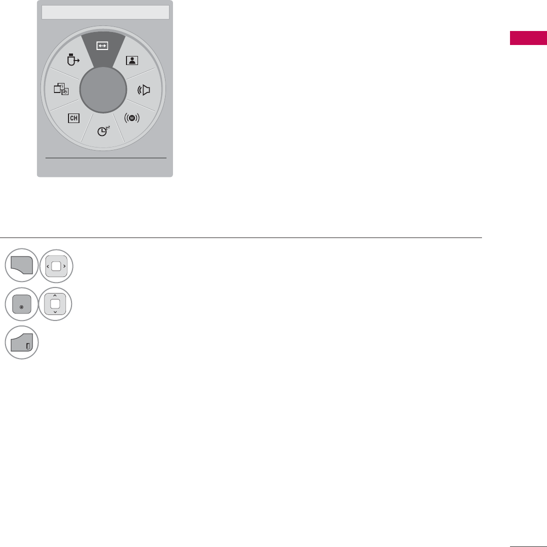
71
WATCHING TV / CHANNEL CONTROL
A
ᯙ
܁$VSHFW5DWLR۽ ᯳Aspect Ratio: Selects your desired picture format.
ᰗPicture Mode: Selects the desired preset picture setting.
ᰘSound Mode: Selects the desired preset sound setting.
ᰄMulti Audio: Changes the audio language (Digital signal).
ᰄSAP: Selects MTS sound (Analog signal).
Sleep Timer: Select the amount of time before your TV
turns off automatically.
ᰃDel/Add: Select channel you want to add or delete.
ᰔCaption: Select on or off.
᯲USB Device: Select “Eject” in order to eject a USB device.
QUICK MENU
Your TV's OSD (On Screen Display) may differ slightly from what is shown in this manual.
Q.Menu (Quick Menu) is a menu of features which users might use frequently.
1
Q.MENU
Display each menu.
2
ENTER
Make appropriate adjustments.
3
EXIT
Return to TV viewing.
ᰙ([LW
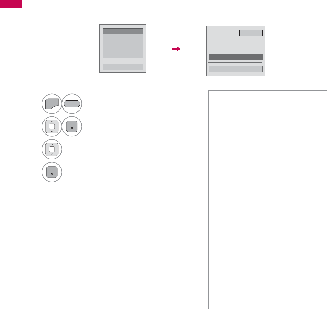
WATCHING TV / CHANNEL CONTROL
WATCHING TV / CHANNEL CONTROL
72
CUSTOMER SUPPORT
Software Update
ᯡ6RIWZDUH8SGDWH
۳3LFWXUH7HVW
۳6RXQG7HVW
۳3URGXFW6HUYLFH,QIR
۳1HWZRUN7HVW
&ORVH
6RIWZDUH8SGDWH 2Q
ؒ&XUUHQW9HUVLRQ
&KHFN8SGDWH9HUVLRQ
&ORVH
You can update the TV with the latest software to enhance the product operation and/or add new fea-
tures.
You can update the software by connecting the TV directly to the software update server.
The Software Update function may not work properly depending on your internet environment. In this
case, you can obtain the latest software from the authorized LG Electronics Service Center then update
your TV.
1
MENU
Select Customer Support.
2
ENTER
Select Software Update.
3Select Check Update Version to check
the newest version.
4
ENTER
RED
ᯫ
The software downloading time will
vary depending on the software size
and network conditions.
ᯫ
During the software update proce-
dure, do not turn off the TV or dis-
connect AC power, or disconnect the
LAN cable.
ᯫ
After software update, you can con-
firm the update software version at
software Update menu.
ᯫ
When update is completed, the TV
will restart automatically in 5 sec-
onds.
ᯫ
The TV functions may be improved
or changed by software update.
ᯫ
The available time or functionality of
NetCast menu may be depends on
your ISP network conditions.
ᯫ
When an update is completed, some
CHANNEL, PICTURE, and AUDIO
menu settings may need resetting.
ᯫ
This TV cannot be updated to previ-
ous software version.
ᯫ
Use the “Check Update Version” but-
ton to update the latest software on
the Network server manually.
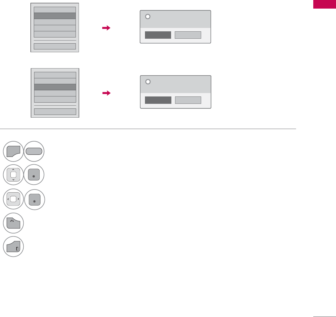
73
WATCHING TV / CHANNEL CONTROL
Picture Test/Sound Test
This function is a customer support function that can execute picture and sound tests.
۳6RIWZDUH8SGDWH
۳3LFWXUH7HVW
ᯡ6RXQG7HVW
۳3URGXFW6HUYLFH,QIR
۳1HWZRUN7HVW
&ORVH
1R
Yes
'R\RXKDYHDVRXQGSUREOHPLQWKLV
VFUHHQ"
"
1
MENU
Select Customer Support.
2
ENTER
Select Picture Test or Sound Test.
3
ENTER
Select Yes.
4
BACK
Return to the previous menu.
EXIT
Return to TV viewing.
۳6RIWZDUH8SGDWH
ᯡ3LFWXUH7HVW
۳6RXQG7HVW
۳3URGXFW6HUYLFH,QIR
۳1HWZRUN7HVW
&ORVH
1R
Yes
'R\RXKDYHDSUREOHPLQWKLVWHVW
VFUHHQ"
"
RED
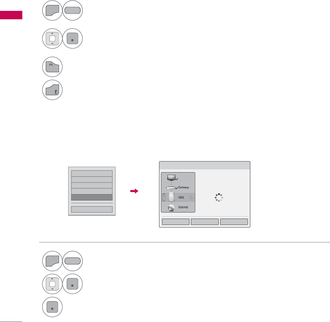
WATCHING TV / CHANNEL CONTROL
WATCHING TV / CHANNEL CONTROL
74
Product/Service Info.
Network Test
۳6RIWZDUH8SGDWH
۳3LFWXUH7HVW
۳6RXQG7HVW
۳3URGXFW6HUYLFH,QIR
ᯡ1HWZRUN7HVW
&ORVH
This function shows support and product information.
Customer Service Center can differ by country.
Check the newtwork status.
1
MENU
Select Customer Support.
2
ENTER
Select Product/Service Info..
You can check the various
product/Service infomation
based on your model.
3
BACK
Return to the previous menu.
EXIT
Return to TV viewing.
1
MENU
Select Customer Support.
2
ENTER
Select Network Test.
3
ENTER
Check the newtwork status.
RED
RED
1HWZRUN6HWWLQJ
1HWZRUNFRQQHFWLQJ
6HWWLQJ 7HVW &ORVH
79

75
WATCHING TV / CHANNEL CONTROL
SIMPLE MANUAL
You can easily and effectively access the TV information by viewing a simple manual on the TV.
During the Simple Manual operation, audio will be muted.
1
MENU
Select Simple Manual.
2Select the part of the manual you would like to see.
Go to the Index page.
Play the Simple Manual automatically or manually.
3
EXIT
Return to TV viewing.
RED
BLUE
GREEN
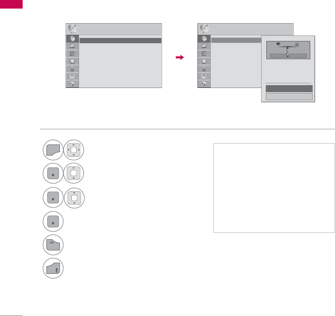
WATCHING TV / CHANNEL CONTROL
WATCHING TV / CHANNEL CONTROL
76
CHANNEL SETUP
Auto Scan (Auto Tuning)
Automatically finds all channels available through antenna or cable inputs, and stores them in memory
on the channel list.
Run this function if you change your residence or move the TV.
Auto Tuning memorizes only the channels available at the time.
1
MENU
Select CHANNEL.
2
ENTER
Select Auto Tuning.
3
ENTER
Select Start.
4
ENTER
Run Auto tuning.
5
BACK
Return to the previous menu.
EXIT
Return to TV viewing.
ᯫ
The TV will ask for a password if
parental control has been activated
(LOCK Menu). Use the password you
set up in the LOCK Menu to allow a
channel search.
ᯫ
The maximum number of channels
the TV can store is 1000.
ᯫ
Found channels are grouped in the
order of DTV, TV, Cable DTV and
Cable TV.
&+$11(/ &+$11(/
ᯒ0RYHᯙ(QWHU ᯒ0RYHᯙ(QWHU
ᯱ
ᯙ
ؒ$XWR7XQLQJ
ؒ0DQXDO7XQLQJ
ؒ&KDQQHO(GLW
ؒ$XWR7XQLQJ
ؒ0DQXDO7XQLQJ
ؒ&KDQQHO(GLW
&KHFN\RXUDQWHQQDFRQQHFWLRQ
7KHSUHYLRXVFKDQQHOLQIRUPDWLRQ
ZLOOEHXSGDWHGGXULQJ$XWR7XQLQJ
$QWHQQD
&DEOH
6WDUW
&ORVH
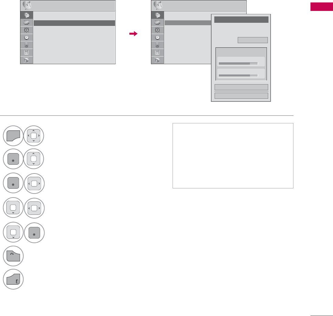
77
WATCHING TV / CHANNEL CONTROL
Add/Delete Channel (Manual Tuning)
When selecting DTV or Cable DTV input signal in Manual Tuning, you can view the on-screen signal
strength monitor to see the quality of the signal being received.
1
MENU
Select CHANNEL.
2
ENTER
Select Manual Tuning.
3
ENTER
Select DTV,TV,Cable DTV,
or Cable TV.
4Select channel you want to
add or delete.
5
ENTER
Select Add or Delete.
6
BACK
Return to the previous menu.
EXIT
Return to TV viewing.
ᯫ
The TV will ask for a password if
parental control has been activated
(LOCK Menu). Use the password you
set up in the LOCK Menu to allow a
channel search.
ᯫ
The maximum number of channels
the TV can store is 1000.
&+$11(/ &+$11(/
ᯒ0RYHᯙ(QWHU ᯒ0RYHᯙ(QWHU
ؒ$XWR7XQLQJ
ؒ0DQXDO7XQLQJ
ؒ&KDQQHO(GLW
&KDQQHO
6HOHFWFKDQQHOW\SHDQG5)FKDQQHO
QXPEHU
܁
'79
۽
2
&ORVH
'HOHWH
'79
ؒ6LJQDO6WUHQJWK
ؒ6LJQDO4XDOLW\
ᯐ
ᯙ
ؒ$XWR7XQLQJ
ؒ0DQXDO7XQLQJ
ؒ&KDQQHO(GLW
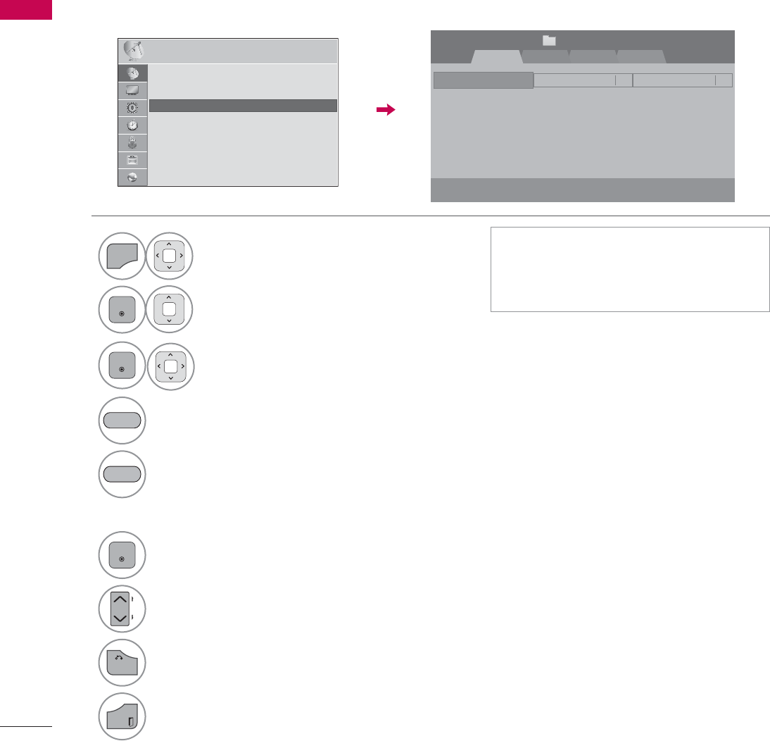
WATCHING TV / CHANNEL CONTROL
WATCHING TV / CHANNEL CONTROL
78
Channel Editing
The channels in the Channel Edit List are displayed in black and the channels deleted from the Channel
Edit List are displayed in blue.
When a channel number is deleted, it means that you will be unable to select it using CHنهbutton
during TV viewing. If you wish to select the deleted channel, directly enter the channel number with the
NUMBER buttons or select it in the Channel Edit menu.
ᯫ
Keep pressing the ᰜbutton and use
the
or
>
buttons to move between
DTV, TV, Cable DTV and Cable TV.
1
MENU
Select CHANNEL.
2
ENTER
Select Channel Edit.
3
ENTER
Select a channel.
4Add or delete a channel.
Block or unblock the channel.
You can block/unblock channels even if
you select “Lock system-Off” in the LOCK
menu.
ENTER
Switch to the chosen channel number.
CH
P
A
G
E
Move the pages when the channel list is
too long.
5
BACK
Return to the previous menu.
EXIT
Return to TV viewing.
BLUE
YELLOW
&+$11(/ ᯒ0RYHᯙ(QWHU
5-13-17-1
ᯙ&+&KDQJH
'79 79 &DEOH'79 &DEOH79
ᯒ1DYLJDWLRQ ᱇3DJH&KDQJH ᯕ%ORFN8QEORFN ᯕ$GG'HOHWH
᱆)DYRULWH&K
&KDQQHO(GLW 3DJH
ᱭ)DYRULWH&K*URXS ᰙ3UHYLRXV
)DYRULWH*URXS A
ᯙ
ᯰ
ؒ$XWR7XQLQJ
ؒ0DQXDO7XQLQJ
ؒ&KDQQHO(GLW
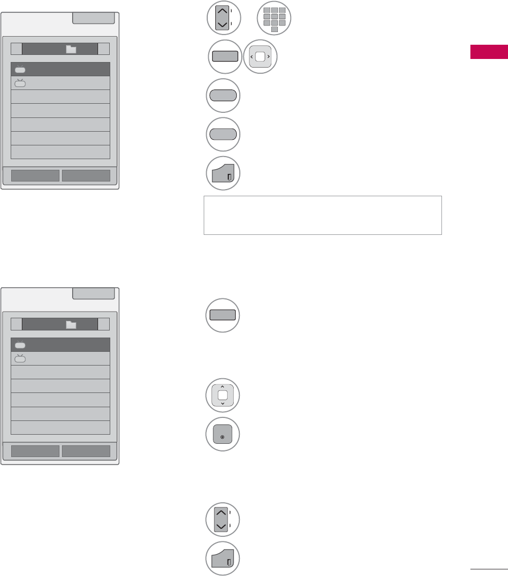
79
WATCHING TV / CHANNEL CONTROL
FAVORITE CHANNEL SETUP
Favorite Channels are a convenient feature that lets you quickly select channels of your choice without
waiting for the TV to select all the in-between channels.
1
FAV
MARK
CHAR/NUM
Display the Favorite channel list.
1Select a channel.
2
ENTER
Switch to the chosen channel number.
1
CH
P
A
G
E
Turn the pages.
2
EXIT
Return to TV viewing.
ᯚᯛ)DYRULWH&K*URXS
ᯚᯛ)DYRULWH&K*URXS
)DYRULWH/LVW
)DYRULWH/LVW
ᰙ([LW
ᰙ([LW
܁*URXSA۽
܁*URXSA۽
DTV
DTV
DTV
DTV
ᯕ&K5HJ
ᯕ&K5HJ
ᯕ&K(GLW
ᯕ&K(GLW
FAVORITE CHANNEL LIST
Selecting a channel in the favorite
channel list
Paging through a favorite channel
list
Displaying the favorite channel list
12 ABC 3 DEF
4 GHI 5 JKL 6
MNO
7
PQRS
8 TUV
0
9
WXYZ
1or
CH
P
A
G
E
Select your desired channel.
2
FAV
MARK
CHAR/NUM
Select your desired favorite
channel group from A to D.
3Register or cancel the current channel
in favorite channel list.
Go to the “CHANNEL menu - Channel
Edit”.
4
EXIT
Return to TV viewing.
YELLOW
BLUE
ᯫ
You can also setup Favorite List in the
CHANNEL menu - Channel Edit.
ᯱ
ᯙ
ᯱ
ᯙ
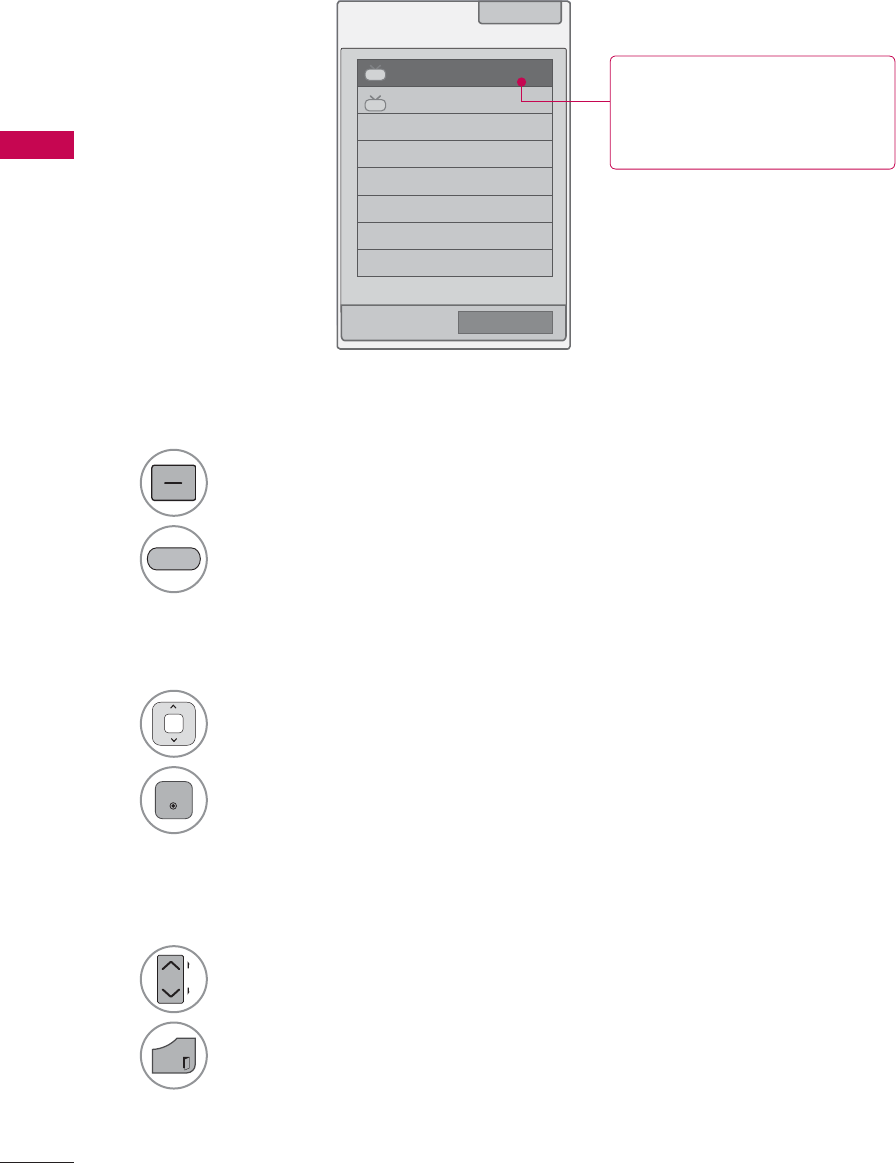
WATCHING TV / CHANNEL CONTROL
WATCHING TV / CHANNEL CONTROL
80
CHANNEL LIST
You can check which channels are stored in the memory by displaying the channel list.
&KDQQHO/LVW ᰙ([LW
DTV
ᯢ
DTV
ᯕ&K(GLW
1Select a channel.
2
ENTER
Switch to the chosen channel number.
1
LIST
Display the Channel List.
Tune to the “CHANNEL menu - Channel Edit”.
1
CH
P
A
G
E
Turn the pages.
2
EXIT
Return to TV viewing.
Selecting a channel in the channel list
Paging through a channel list
Displaying Channel List
BLUE
This padlock is displayed
when the channel is locked
with parental control.
ᯱ
ᯙ
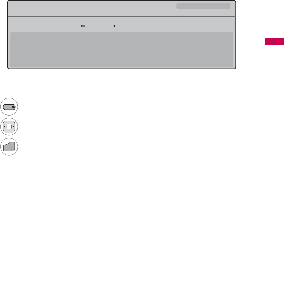
WATCHING TV / CHANNEL CONTROL
81
Displaying Channel Information
CHANNEL INFORMATION
1
INFO
Show the current channel program Information on the screen.
2Show a previous or next channel’s pro gram information
3
EXIT
Return to TV viewing.
0XOWLOLQJXDO᯿&DSWLRQᰇLᯢ793*'/69
%ULHI,QIR7LWOH7HVW
᯦'79&11 ᯐ&K&KDQJH۽1H[Wᯙ:DWFK
$0 $0
1RLQIRUPDWLRQ
6DUDK%UDGOH\6WHYH*UD\DQG%UHQGRQ3RQJLDSUHVHQWWKHODWHVWLQIDVKLRQWKHDUWVHQWHUWDLQPHQWOLIHVW\OHDQGFRRNLQJ
ZLWKUHJXODUDQGVSHFLDOJXHVWV
6DUDK%UDGOH\6WHYH*UD\DQG%UHQGRQ3RQJLDSUHVHQWWKHODWHVWLQIDVKLRQWKHDUWVHQWHUWDLQPHQWOLIHVW\OHDQGFRRNLQJ
ᯱ
ᯕ8S
ᯕ'RZQ
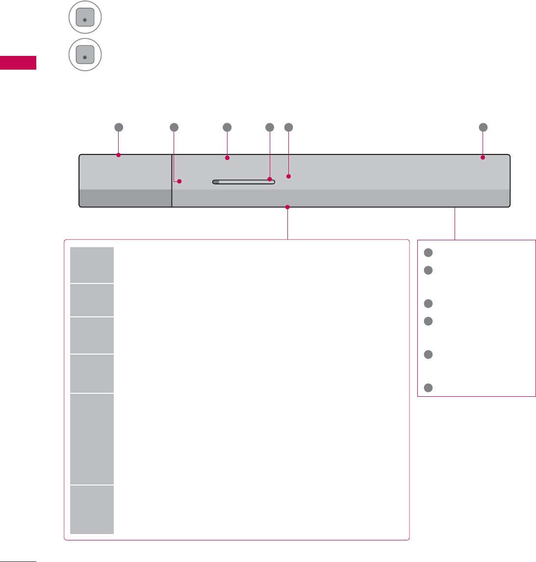
WATCHING TV / CHANNEL CONTROL
WATCHING TV / CHANNEL CONTROL
82
CHANNEL BRIEF INFORMATION
Brief Info shows the present screen information.
1
ENTER
Shows the current channel’s brief info screen.
2
ENTER
Return to TV viewing.
1Program title
2Day, Month, Year,
Present time
3Program start time
4Program progress
bar
5Program finish
time
6Banner information
6XQ)HE$0
0XOWLOLQJXDO᯿&DSWLRQᰇLᯢ793*'/69
$0 $0
%ULHI,QIR7LWOH7HVW
1H[W$01HZV
&11
᯦'79
ᱏ
6 3 11 4 5 2
Multilingual : The program contains two or more audio servic-
es. Use the Q.MENU menu to select wanted Audio.
᯿Caption : The program contains one or more caption services.
Use the Q.MENU menu to select wanted Closed caption.
Dolby Digital: The program contains a Dolby Digital audio
signal in TV and HDMI input source.
ᰆThe original aspect ratio of the video is 4:3
ᰇThe original aspect ratio of the video is 16:9 (wide)
480i
480p
720p
1080i
1080p
The video resolution is 720x480i
The video resolution is 720x480p
The video resolution is 1280x720p
The video resolution is 1920x1080i
The video resolution is 1920x1080p
ᯢ
V-Chip: The program contains V-Chip information. Refer to
the LOCK menu: A (Age), D (Dialogue), L (Language), S (Sex),
V (Violence), FV (Fantasy Violence)
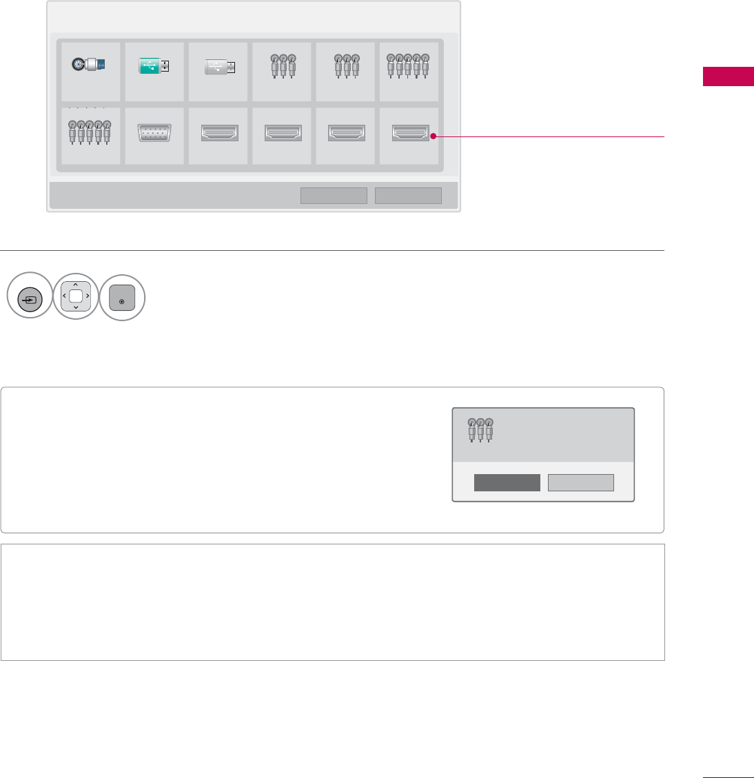
83
WATCHING TV / CHANNEL CONTROL
ᯫ
When new external device is connected, this popup
menu is displayed automatically.
If selecting Yes, you can select input source that you
want to appreciate.
ᯫ
But, when selecting “SIMPLINK - On”, popup menu for
HDMI input will not be displayed.
Disconnected inputs are inactive
(grayed out)
INPUT LIST
Only these input signals which are connected to a TV can be activated and selected.
1
INPUT
ENTER
Select the desired input source.
ᯫ
You can also select the desired input source in the INPUT menu.
ᯫ
TV: Select it to watch over-the-air, cable and digital cable broadcasts.
ᯫ
AV: Select them to watch a VCR or other external equipment.
ᯫ
Component: Select them to watch DVD or a Digital set-top box.
ᯫ
RGB-PC: Select it to view PC input.
ᯫ
HDMI: Select them to watch high definition devices.
1R
Yes
1HZH[WHUQDOLQSXWLVFRQQHFWHG
'R\RXZDQWWRXVHWKLV"
$9
,QSXW/LVW ᯒ0RYH ᯙ(QWHU
79 86% 86% $9 $9 &RPSRQHQW
&RPSRQHQW 5*%3& +'0, +'0, +'0, +'0,
ᯕ,QSXW/DEHO ᰙ([LW
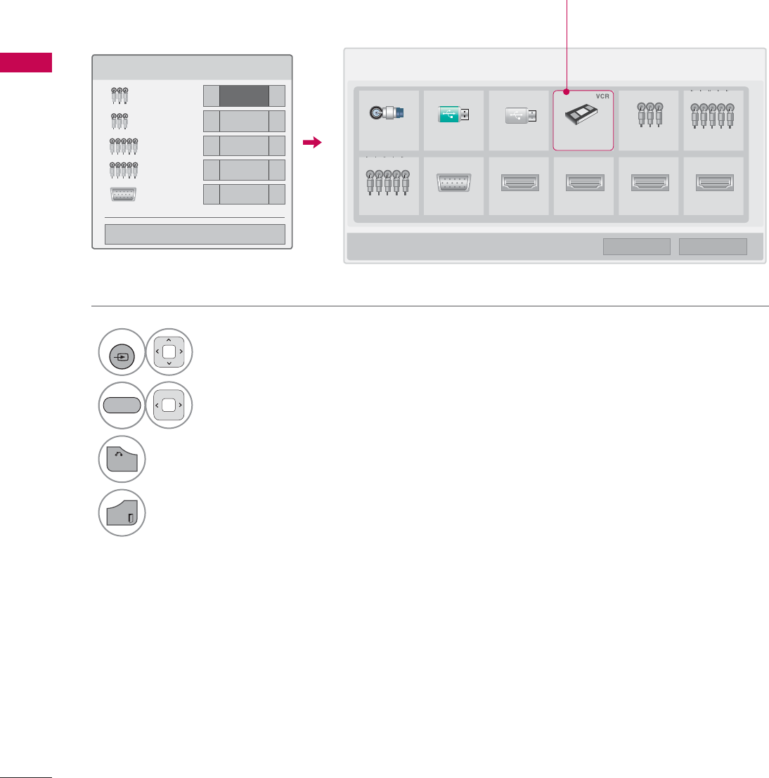
WATCHING TV / CHANNEL CONTROL
WATCHING TV / CHANNEL CONTROL
84
INPUT LABEL
This indicates which device is connected to which input port.
1
INPUT
Select the desired input
source.
2Select the label.
3
BACK
Return to the previous menu.
EXIT
Return to TV viewing.
,QSXW/DEHO
$9 ܁9&5 ۽
$9 ܁۽
&RPSRQHQW ܁۽
&RPSRQHQW ܁۽
5*%3& ܁۽
ᯝ
&ORVH
BLUE
,QSXW/LVW ᯒ0RYH ᯙ(QWHU
79 86% 86% $9 $9 &RPSRQHQW
&RPSRQHQW 5*%3& +'0, +'0, +'0, +'0,
ᯕ,QSXW/DEHO ᰙ([LW
ie) Change the input label using
Blue button
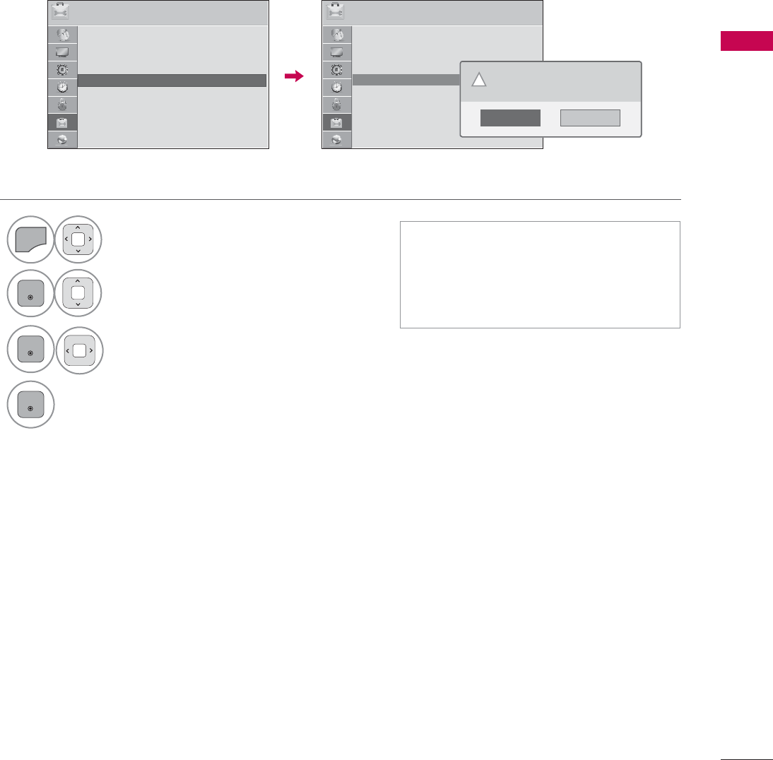
85
WATCHING TV / CHANNEL CONTROL
RESET TO FACTORY DEFAULT (INITIAL SETTING)
This function resets the TV to factory default and erases all stored channels.
ᯫ
When selecting “Lock System - On”
in the LOCK menu, the message to
enter the password appears.
ᯫ
If you forget your password, press
“0-3-2-5” on the remote control.
237,21 ᯒ0RYHᯙ(QWHU 237,21 ᯒ0RYHᯙ(QWHU
ؒ/DQJXDJH
ؒ&DSWLRQ 2II
ؒ3RZHU,QGLFDWRU
ؒ,QLWLDO6HWWLQJ
ؒ0RGH6HWWLQJ +RPH8VH
ᯐ
ᯙ
ؒ/DQJXDJH
ؒ&DSWLRQ 2II
ؒ3RZHU,QGLFDWRU
ؒ,QLWLDO6HWWLQJ
ؒ0RGH6HWWLQJ +RPH8VH
1
MENU
Select OPTION.
2
ENTER
Select Initial Setting.
3
ENTER
Select Yes.
4
ENTER
TV turns off automatically and starts
factory reset.
1R
Yes
$OOXVHUVHWWLQJVDQGFKDQQHOVHWWLQJVZLOO
EHUHVHW6WLOOFRQWLQXH"
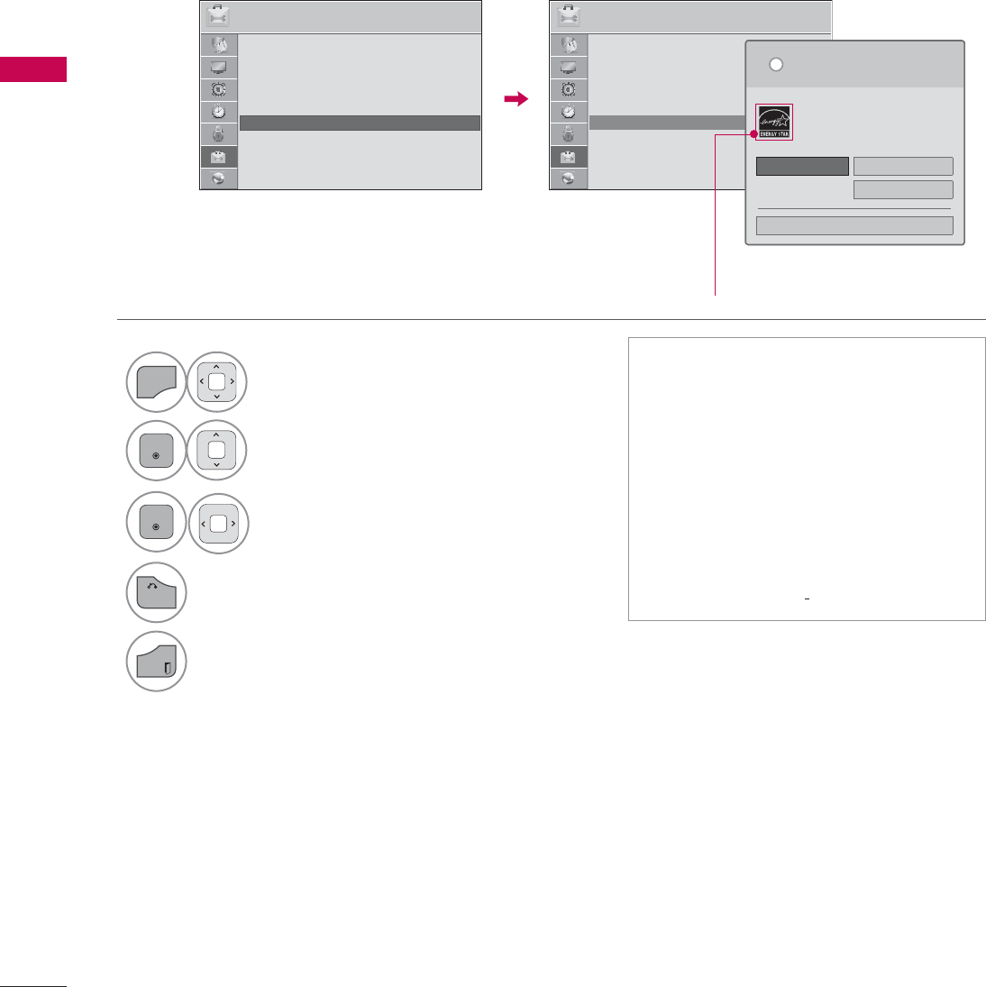
WATCHING TV / CHANNEL CONTROL
WATCHING TV / CHANNEL CONTROL
86
MODE SETTING
Default selection is “Home Use”. We recommend setting the TV to “Home Use” mode for the best
picture in your home environment.
ᯫ
“Store Demo” Mode is only intended
for use in retail environments.
Customers can adjust the “Picture
menu - Picture mode” manually while
inspecting the TV, but the TV will
automatically return to preset in-
store mode after 5 minutes.
ᯫ
“Store Demo” Mode is an optimal
setting for displaying at stores. “Store
Demo” mode initializes the TV to set
the image quality.
237,21 ᯒ0RYHᯙ(QWHU 237,21 ᯒ0RYHᯙ(QWHU
ؒ/DQJXDJH
ؒ&DSWLRQ 2II
ؒ3RZHU,QGLFDWRU
ؒ,QLWLDO6HWWLQJ
ؒ0RGH6HWWLQJ +RPH8VH
1
MENU
Select OPTION.
2
ENTER
Select Mode Setting.
3
ENTER
Select Home Use.
4
BACK
Return to the previous menu.
EXIT
Return to TV viewing.
ᯙ
ᯰ
ؒ/DQJXDJH
ؒ&DSWLRQ 2II
ؒ3RZHU,QGLFDWRU
ؒ,QLWLDO6HWWLQJ
ؒ0RGH6HWWLQJ +RPH8VH
6HOHFWLQJWKHHQYLURQPHQW
&KRRVHWKHVHWWLQJPRGH\RXZDQW
L
+RPH8VH 6WRUH'HPR
ؒ'HPR0RGH 2II
&ORVH
6HOHFW>+RPH8VH@ZKHQVHWWLQJ79XS
LQKRPH<RXFDQDGMXVWSLFWXUHTXDOLW\
DFFRUGLQJO\WKURXJK3LFWXUH0RGHPHQX
RSWLRQ
For LED LCD TV
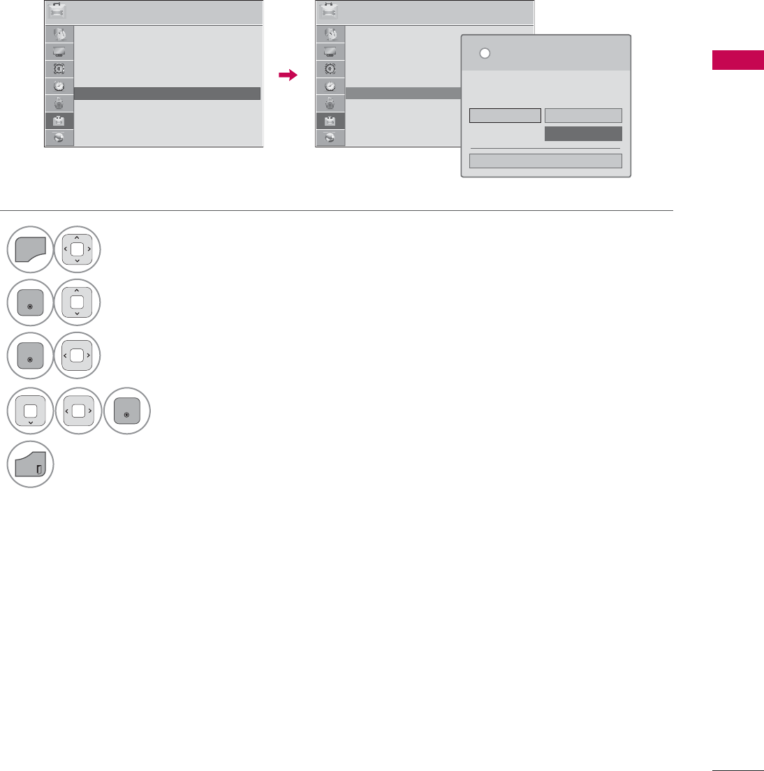
87
WATCHING TV / CHANNEL CONTROL
DEMO MODE
Displays a slide show to explain the various feature of this TV.
237,21 ᯒ0RYHᯙ(QWHU 237,21 ᯒ0RYHᯙ(QWHU
ؒ/DQJXDJH
ؒ&DSWLRQ 2II
ؒ3RZHU,QGLFDWRU
ؒ,QLWLDO6HWWLQJ
ؒ0RGH6HWWLQJ 6WRUH'HPR
6HOHFWLQJWKHHQYLURQPHQW
&KRRVHWKHVHWWLQJPRGH\RXZDQW
6HOHFW>6WRUH'HPR@IRULQVWRUHGVSOD\)RUXVH
LQKRPHVHOHFW>+RPH8VH@
L
+RPH8VH 6WRUH'HPR
ؒ'HPR0RGH 2II
&ORVH
1
MENU
Select OPTION.
2
ENTER
Select Mode Setting.
3
ENTER
Select Store Demo.
4
ENTER
Select On.
5
EXIT
Return to TV viewing.
After a while, Demo Mode. starts.
If you want to stop the demo, press any
button (Except VOL +, - and MUTE button).
ᯙ
ᯰ
ؒ/DQJXDJH
ؒ&DSWLRQ 2II
ؒ3RZHU,QGLFDWRU
ؒ,QLWLDO6HWWLQJ
ؒ0RGH6HWWLQJ +RPH8VH
WATCHING TV / CHANNEL CONTROL
WATCHING TV / CHANNEL CONTROL
88
Off &LQHPD&LQHPD
Game Sport
AV MODE
AV Mode toggles through preset Video and Audio settings.
1
AV MODE
Press the AV MODE button repeatedly to
select the desired source.
2
ENTER
ᯫ
If you select “Cinema / Cinema”
in AV mode, Cinema / Cinema
will be selected both for “PICTURE
menu - Picture Mode” and “AUDIO
menu - Sound Mode” respectively.
ᯫ
If you select “Off” in AV mode, the
“Picture Mode” and “Sound Mode”
return to previous selected value.
ᯫ
Off: Disables the AV MODE.
ᯫ
Cinema: Optimizes video and audio
for watching movies.
ᯫ
Sport: Optimizes video and audio for
watching sports events.
ᯫ
Game: Optimizes video and audio for
playing games.
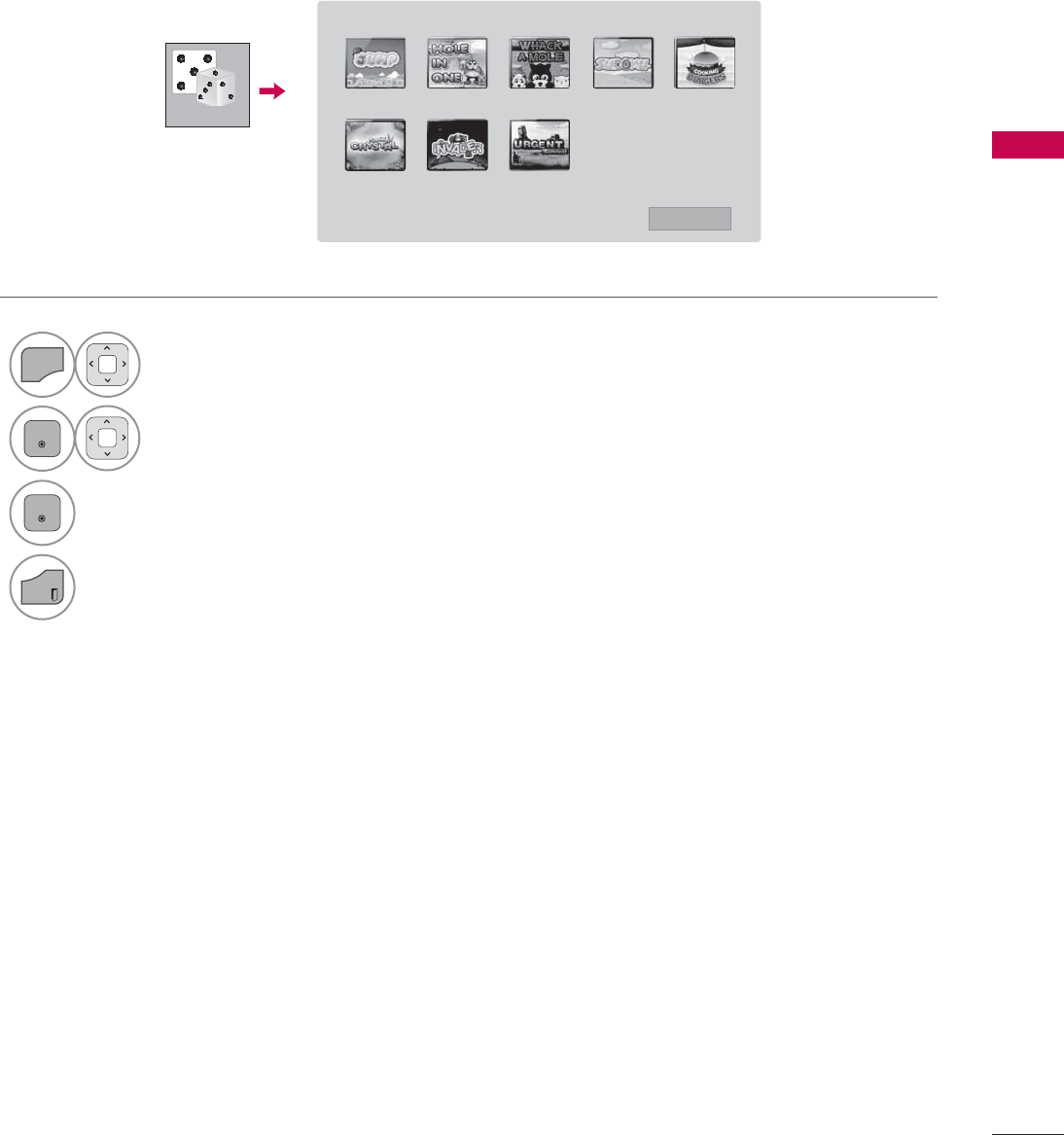
89
WATCHING TV / CHANNEL CONTROL
GAME
Allows you to enjoy the games installed on the TV.
1
MENU
Select GAME.
2
ENTER
Select the desired game.
3
ENTER
Enter the selected game mode.
4
EXIT
Return to TV viewing.
*$0( -803 +2/(,121( :+$&.$02/( 68'2.8 &22.,1*%85*(5
6$9,1*&5<67$/ ,19$'(5 85*(176859,9$/
᰿([LW
*$0(
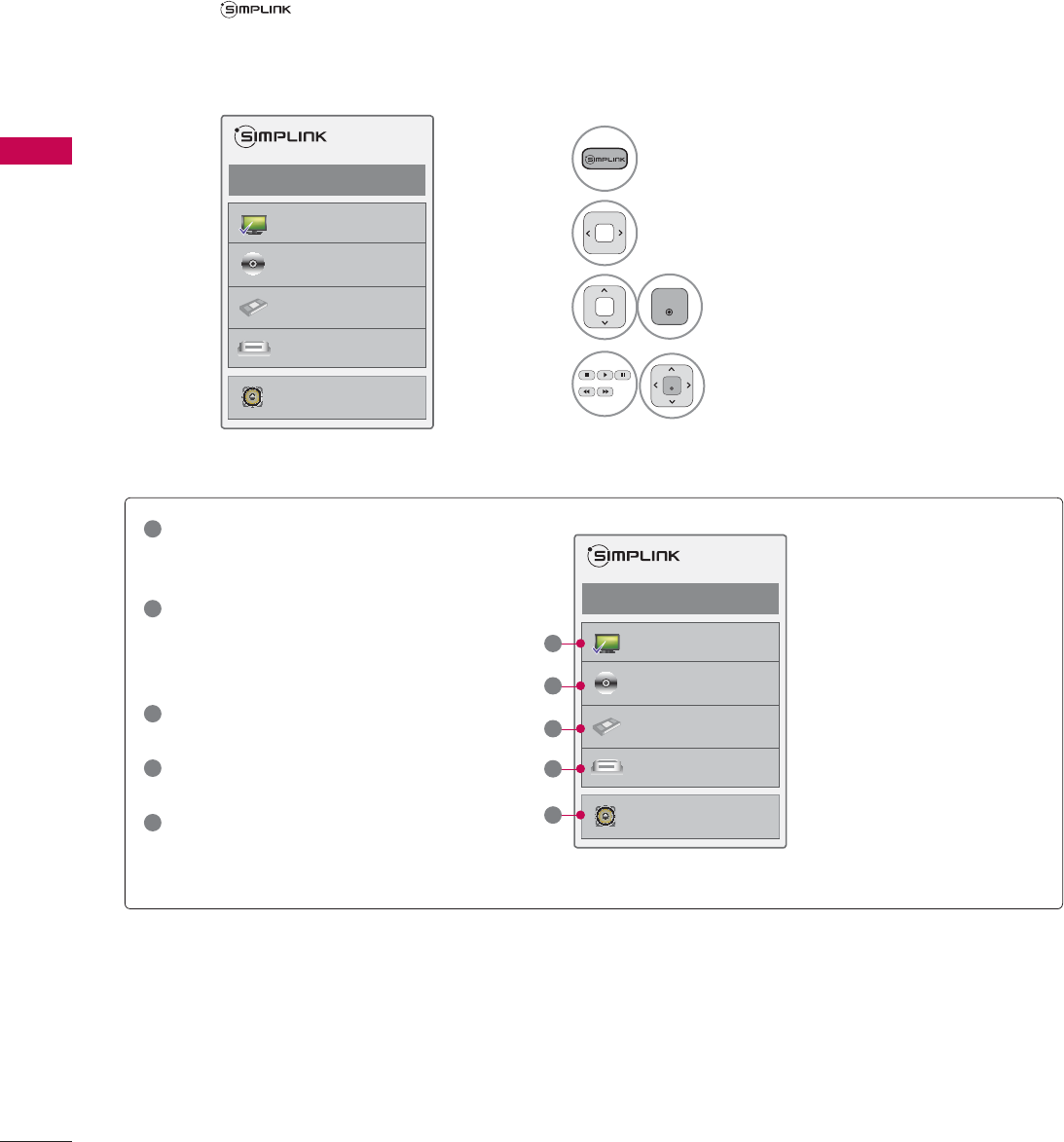
WATCHING TV / CHANNEL CONTROL
WATCHING TV / CHANNEL CONTROL
90
SIMPLINK
SIMPLINK allows you to control and play other AV devices connected with HDMI cable without addi-
tional cables and settings. This TV may work with devices with HDMI-CEC support, but only devices
with the logo are fully supported.
SIMPLINK can be turned on and off in the user menus.
1Display SIMPLINK menu.
2Select On.
3
ENTER
Select the desired device.
4
ENTER
Control connected AV devices.
ᯙ(QWHUᰙ([LW
܁2Q۽
:DWFK79
܁۽
܁۽
+''5HFRUGHU
܁۽
',6&
+'''9'5
9&5
+'+7
6SHDNHU
796SHDNHU
ᯙ(QWHUᰙ([LW
܁2Q۽
:DWFK79
܁۽
܁۽
+''5HFRUGHU
܁۽
',6&
+'''9'5
9&5
+'+7
6SHDNHU
796SHDNHU
1
TV viewing: Switch to the previous TV
channel regardless of the current
mode.
2
DISC playback: Select and play discs.
When multiple discs are available, the
disc devices are conveniently displayed
at the bottom of the screen.
3
VCR playback: Control the connected
VCR.
4
HDD Recordings playback: Control
recordings stored in HDD.
5
Audio Out to Home Theater speaker/
Audio Out to TV: Select Home Theater
speaker or TV speaker for Audio Out.
Ź
When no device is con-
nected (displayed in gray)
Ź
Selected Device
Ź
When a device is conect-
ed (displayed in bright
color)
1
2
3
4
5

91
WATCHING TV / CHANNEL CONTROL
SIMPLINK Functions
ᯫ
Direct Play: After connecting AV devices to the TV, you can directly control the devices and play media
without additional settings.
ᯫ
Select AV device: Enables you to select one of the AV devices connected to the TV.
ᯫ
Disc playback: Control connected AV devices by pressing the ᰜᰝ
!
, ENTER, ᰦ, ᰧ, ᰨ, ᰪand ᰩ but-
tons.
ᯫ
Power off all devices: When you power off the TV, all connected devices are turned off.
ᯫ
Switch audio-out: Offers an easy way to switch audio-out.
ᯫ
Sync Power on: When the equipment with Simplink function connected HDMI terminal starts to play,
The TV will automatically turn on.
Note: To operate SIMPLINK, an HDMI cable over Version 1.3 with *CEC function should be used. (*CEC:
Consumer Electronics Control).
(A device, which is connected to the TV through a HDMI cable but does not support SIMPLINK, does
not provide this function)
!
NOTE
ŹConnect the HDMI/DVI IN or HDMI IN terminal of the TV to the rear terminal (HDMI terminal) of
the SIMPLINK device with the HDMI cable
ŹWhen you switch the Input source with the INPUT button on the remote control, the SIMPLINK
device will stop.
ŹWhen you select a device with home theater functionality, the sound output automatically switches
to the home theater speakers and the TV speakers are turned off.
ŹIf a connected SIMPLINK home theater system doesn’t play the audio from the TV, connect the
DIGITAL AUDIO OUT terminal on the back of the TV to the DIGITAL AUDIO IN terminal on the
back of the SIMPLINK device with an OPTICAL cable.
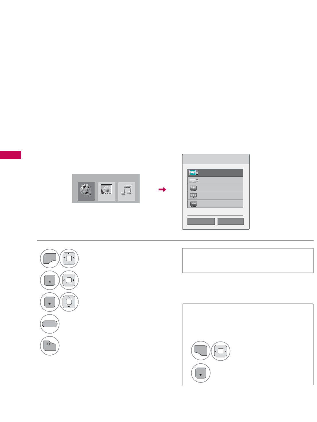
MY MEDIA
MY MEDIA
92
ENTRY MODE
The My Media menu will open automatically when you insert a USB drive. My Media can also be
accessed by choosing My Media in the user menu.
After choosing the desired type of media, choose a device to open files from. The options are: USB
device, CIFS (Windows Sharing), or DLNA.
When removing the USB device
Select the USB Device menu before
removing the USB device.
MY MEDIA
ᯫ
This TV can view JPG image files, HD DivX
files and play MP3 audio files.
1
Q.MENU
Select USB Device.
2
ENTER
Select Eject.
3OHDVHVHOHFWWKHGHYLFH
86%/DEHO
86%/DEHO
&,)6
&,)6
'/1$
ᯙ'HYLFH6HOHFWLRQ
ᯕ6HDUFK ᰙ3UHYLRXV
1
MENU
Select MY MEDIA.
2
ENTER
Select Movie List, Photo List
or Music List.
3
ENTER
Select the desired device.
Search other network device.k
4
BACK
Return to the previous menu.
BLUE
0RYLH/LVW
0<0(',$
Photo/LVW 0XVLF/LVW
*CIFS: This feature is not available for all models.
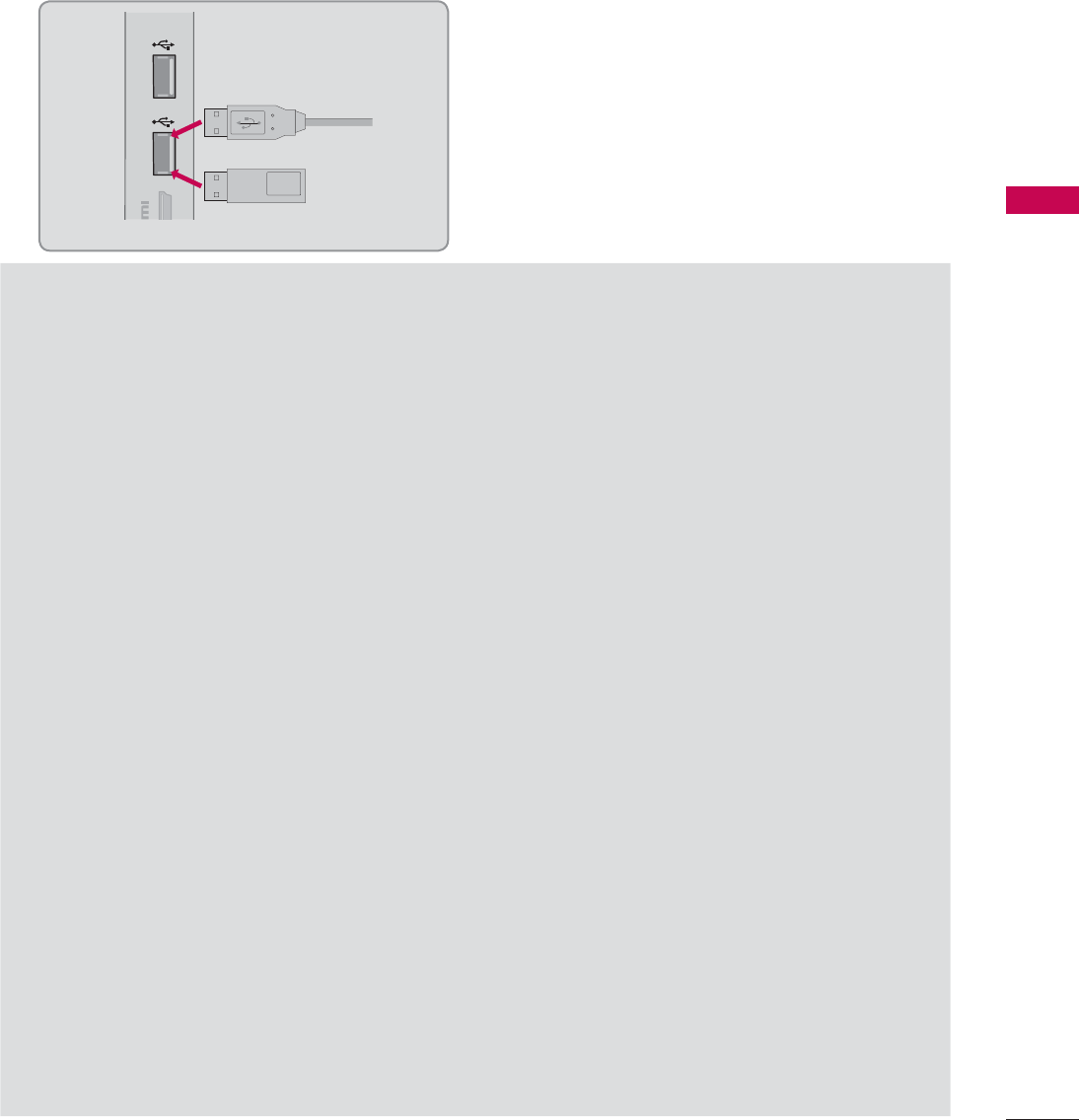
93
MY MEDIA
CONNECTION METHOD
USB Connection
Connect the USB device to the USB IN jack on the side of TV.
1
Precautions when using the USB device
ŹOnly a USB storage device is recognizable.
ŹConnecting a USB storage device through a USB hub is not supported.
ŹA USB storage device which uses its own driver may not be recognized.
ŹThe recognition speed of a USB storage device may depend on each device.
ŹPlease do not turn off the TV or unplug the USB device when the connected USB storage device
is working. When such device is suddenly separated or unplugged, the stored files or the USB
storage device may be damaged.
ŹOnly use a USB storage device which has normal music files, image files, or movie files.
ŹPlease use only a USB storage device which was formatted as a FAT 32 or NTFS file system pro-
vided with the Windows operating system. Others may not be recognized.
ŹSome USB storage devices require a power adapter. The power adapter must be connected in
order to be seen by the TV.
ŹIf a device is not recognized by the TV, try a different cable. Excessively long cables are not sup-
ported.
ŹSome USB storage devices may not be supported or operate properly.
ŹPlease backup important files because data on USB device could be damaged. Data management
is consumer's responsibility and as a result, the manufacturer does not cover data damage.
ŹIf your USB memory device has multiple partitions, or if you use a USB multi-card reader, you can
use up to 4 partitions or USB memory devices.
ŹIn case of USB storage devices formatted as NTFS, deletion is not supported.
ŹFile alignment method of USB storage device is similar to Window XP and file names can be up
to 100 English characters.
ŹThe recommended capacity is 1 TB or less for a USB external hard disk and 32 GB or less for USB
memory.
ŹIf a USB external hard disk with a “Energy Saving” function doesn’t work, turn the hard disk off and
on again to make it work properly. Refer to the user manual of the USB external hard disk.
ŹUSB storage devices below USB 2.0 are supported as well. But they may not work properly in the
movie list.
IN 4
USB IN 1 USB IN 2
Memory Key
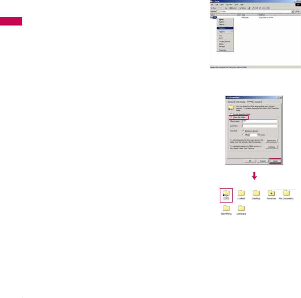
MY MEDIA
MY MEDIA
94
CIFS (Common Internet File System)
Share folder (CIFS: Common Internet File System) Setup
Case 1 (Windows XP)
ᯫ
The method of setting the shared folder may be different by the OS environment.
1Select the folder you wish to share and
then click Sharing.
2Check Share this folder and click Apply.
*This feature is not available for all models.
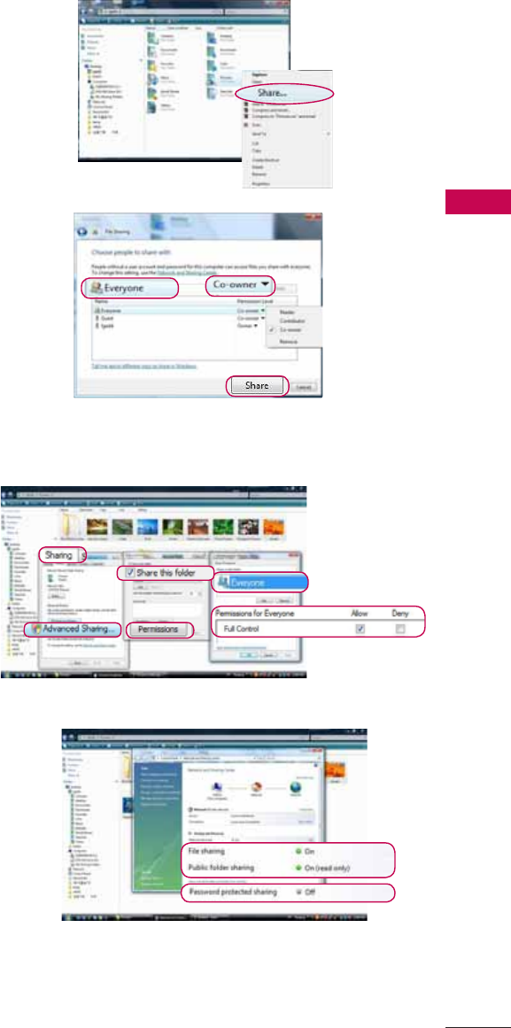
95
MY MEDIA
Case 2 (For Windows Vista)
1Choose the folder that you want to share.
Then, right-click and click Share.
Add the Everyone and click Share.
2Choose the folder that you want to share.
Right-click and click Properties.
Click Advanced Sharing on Sharing tab.
Check Share this folder and click Permission.
Add Everyone and check Full Control - Allow.
3Check File sharing-On, Public folder sharing-
On, and Password protected sharing-Off.
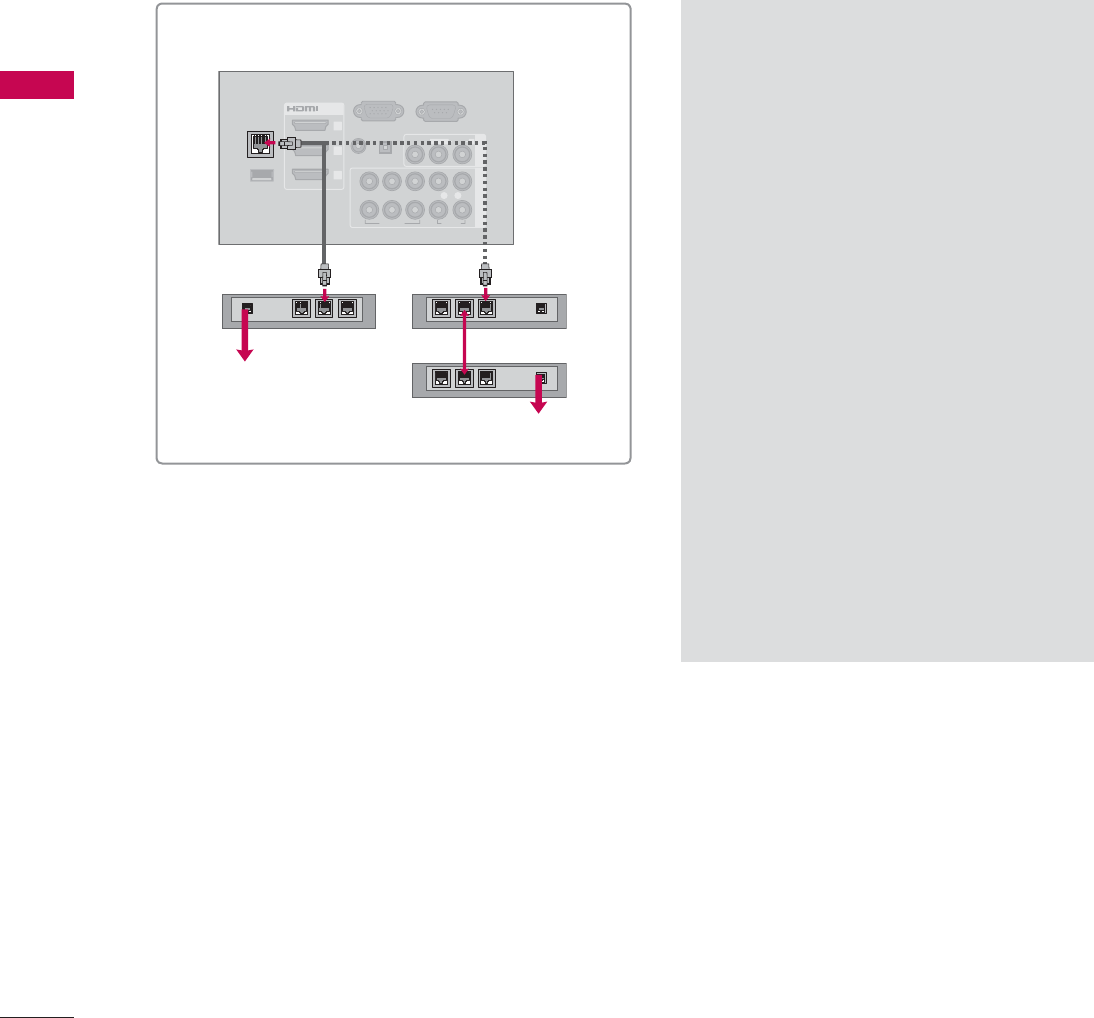
MY MEDIA
MY MEDIA
96
Viewing Files on the Network
You can view the photos, movies or listen to music files from folders shared on the network.
RGB IN (PC)
WIRELESS
CONTROL
(RGB/DVI)
/DVI IN
2
3
1
VIDEO
AUDIO
L(MONO)
R
VIDEO AUDIO
COMPONENT INAV IN 1
AUDIO IN
AUDIO OUT
2
1
LAN
YP
B
P
R
L R
OPTICAL DIGITAL
RS-232C IN
(
SERVICE ONLY)
ꔡ
ŹConnect the PC and TV using a shar-
ing device so that you can see the PC’s
shared files on the TV.
ŹHow to set a share folder may differ
depending on the Windows version.
ŹThe speed may be slow or it may cause
an error if you try to access a folder
from two TVs at the same time.
ŹBecause files could be deleted from a
shared PC, set the user access level to
Read Only.
ŹDo not share any important personal
documents as it may be accessed by a
different PC.
ŹIf you rename or disable a shared
folder on the PC after mounting, you
cannot mount it again.
ŹIf the status of the network or a share
folder on the PC is changed, search is
run again when entering the highest
folder in the menu.
ŹMaximum of 32 computers can be
shared.
i.e) LED LCD TV/LCD TV
Broadband
modem
Broadband modem
Router
Broadband Service
Broadband Service
1Set a share folder (CIFS: Common Internet File System) on the PC (Refer to P.94-95).
2Connect the LAN port of the Modem or Router to the LAN port on the TV.
3Repeat step 1-4 on P.92.

97
MY MEDIA
DLNA
About DLNA
This TV is a DLNA Certified digital media product that can display and play movie, photo and music
content from your DLNA Certified network device and DLNA server. The Digital Living Network Alliance
(DLNA) is a cross-industry organization of consumer electronics, computing industry and mobile device
companies. Digital Living provides consumers with easy sharing of digital media through a wired or
wireless network in the home.
The DLNA certification logo makes it easy to find products that comply with the DLNA Interoperability
Guidelines. This unit complies with DLNA Interoperability Guidelines v1.5. When a PC running DLNA
server software or other DLNA compatible device is connected to this TV, some setting changes of
software or other devices may be required. Please refer to the operating instructions for the software or
device for more information.
!
NOTE
ŹThe supplied Nero MediaHome 4 Essentials CD-ROM is a customized software edition only for
sharing files and folders to this TV.
ŹThe supplied Nero MediaHome 4 Essentials software does not support following functions:
Transcoding, Remote UI, TV control, Internet services and Apple iTunes
ŹThis manual explains operations with the English version of Nero MediaHome 4 Essentials as
examples. Follow the explanation referring to the actual operations of your language version.

MY MEDIA
MY MEDIA
98
Installing Nero MediaHome 4 Essentials
Nero MediaHome 4 Essentials is easy to use DLNA server software for Windows. If you are already
using DLNA server software on your PC, Nero MediaHome is not required. Nero MediaHome is not
required for Windows 7 since it has a built-in DLNA server.
Requirement PC system before you install Nero MediaHome 4 Essentials
ᯫ
Windows® XP (Service Pack 2 or higher), Windows Vista® (no Service Pack required), Windows® XP
Media Center Edition 2005 (Service Pack 2 or higher), Windows Server® 2003
ᯫ
Windows Vista® 64-bit edition (application runs in 32-bit mode)
ᯫ
Hard drive space: 200 MB hard drive space for a typical installation of Nero MediaHome stand-
alone
ᯫ
1.2 GHz Intel® Pentium® III or AMD Sempron™ 2200+ processors
ᯫ
Memory: 256 MB RAM
ᯫ
Graphics card with at least 32 MB video memory, minimum resolution of 800 x 600 pixels, and
16-bit color settings
ᯫ
Windows® Internet Explorer® 6.0 or higher
ᯫ
DirectX® 9.0c revision 30 (August 2006) or higher
ᯫ
Network environment: 100 Mb Ethernet, WLAN (IEEE 802.11b/g/n)

99
MY MEDIA
1Start up your computer, and insert the Nero MediaHome 4 Essentials CD-ROM into your compu-
ter’s CD-ROM drive.
An installation wizard will walk you through the quick and uncomplicated installation process.
2Close all Microsoft Windows programs and exit any anti-virus software that may be running.
3Insert the Nero MediaHome 4 Essentials CD-ROM into your computer’s CD-ROM drive.
4Click Nero MediaHome 4 Essentials. The installation is prepared and the installation wizard appears.
5Click the Next button to display the serial number input screen.
Click Next to go to the next step.
6If you accept all conditions, click I accept the License Conditions check box and click Next.
Installation is not possible without this agreement.
7Click Typical and click Next. The installation process is started.
8If you want to take part in the anonymous collection of data, select the check box and click the
Next button.
9Click the Exit button to complete the installation.

MY MEDIA
MY MEDIA
100
Sharing files and folders
After installing Nero MediaHome, you must add folders you wish to share.
1Double-click the Nero MediaHome 4 Essentials icon on the desktop.
2Click Network icon on the left and define your network name in the Network name field. The
Network name you enter will be recognized by your TV.
3Click Shares icon on the left.
4Click Local Folders tab on the Shared screen.
5Click Add icon to open the Browse Folder window.
6Select the folder containing the files you want to share. The selected folder is added to the list of
shared folders.
7Click Start Server icon to start the server.
!
NOTE
ŹIf the shared folders or files are not displayed on the TV, click the folder on the Local Folders
tab and click Rescan Folder at the More button.
ŹVisit www.nero.com for more information and software tools.

101
MY MEDIA
Playing back shared contents
You can display and play movie, photo and music content stored on your computer or other DLNA
media servers.
1Start the server on your computer or other device that connected on your home network.
!
NOTE
ŹTo play the file on the media server, the TV and the media server must be connected to the
same access point.
ŹBecause the compatibility and available playback functions on the MY MEDIA menu are tested
on the bundle DLNA server (Nero MediaHome 4 Essentials) environment, file requirements and
playback functions on the MY MEDIA may differ depending on media servers.
ŹThe file requirements on this page are not always compatible. There may have some restrictions
by file features and media server’s ability.
ŹMovie thumbnail is not supported in DLNA Movie.
ŹIf there is an unplayable music file in the MY MEDIA menu, the TV will skip the file and play next
file.
ŹThe file information indicated on the screen may not always correct for music and movie files in
MY MEDIA menu
ŹThis TV only supports movie subtitle files supplied by Nero MediaHome 4.
ŹThe subtitle file name and movie file name have to be the same and located at the same folder.
ŹIf subtitle files have been added after a directory has been indexed already, the user has to
remove and re-add the folder to the list of shares.
ŹThe playback and operating quality of the MY MEDIA function may be affected by your home
network condition.
ŹThe files from removable media such as USB drive, DVD-drive etc. on your media server may
not share properly.
ŹWhen playing the Media through DLNA connection, it does not support the DivX file play which
is protected by DRM.
2
MENU
Select MY MEDIA.
3
ENTER
Select Movie List, Photo List or Music List.
4
ENTER
Select the DLNA.
Depending on the media server, this TV may need to get the permission from
the server.
If you want to re-scan available media server, press blue color button.