LG Electronics USA 60PS80UA PLASMA TV/MONITOR User Manual
LG Electronics USA PLASMA TV/MONITOR
Contents
- 1. User manaul 1 of 2
- 2. User manual 2 of 2
User manaul 1 of 2
Please read this manual carefully before operating
your set and retain it for future reference.
The model and serial number of the TV is located
on the back and one side of the TV.
Record it below should you ever need service.
P/NO : SAC33601905 (0903-REV00)
www.lgusa.com / www.lg.ca
This product qualifies for ENERGY STAR in the “factory
default (Home Use)” setting and this is the setting in which
power savings will be achieved.
Changing the factory default picture setting or enabling other
features will increase power consumption that could exceed
the limits necessary to quality for Energy Star rating.
Model:
Serial:
1-800-243-0000 USA, Consumer User
1-888-865-3026 USA, Commercial User
1-888-542-2623 CANADA
LG Customer Information Center
LCD TV PLASMA TV
OWNER’S MANUAL
LCD TV MODELS
42LH50
47LH50
PLASMA TV MODELS
50PS80
60PS80
2
WARNING / CAUTION
The lightning flash with arrowhead
symbol, within an equilateral triangle, is
intended to alert the user to the presence
of uninsulated “dangerous voltage” within the
product’s enclosure that may be of sufficient
magnitude to constitute a risk of electric shock to
persons.
The exclamation point within an equilateral
triangle is intended to alert the user to
the presence of important operating and
maintenance (servicing) instructions in the litera-
ture accompanying the appliance.
TO REDUCE THE RISK OF ELECTRIC SHOCK
DO NOT REMOVE COVER (OR BACK). NO
USER SERVICEABLE PARTS INSIDE. REFER TO
QUALIFIED SERVICE PERSONNEL.
WARNING/CAUTION
TO REDUCE THE RISK OF FIRE AND ELECTRIC
SHOCK, DO NOT EXPOSE THIS PRODUCT TO
RAIN OR MOISTURE.
NOTE TO CABLE/TV INSTALLER
This reminder is provided to call the CATV system
installer’s attention to Article 820-40 of the National
Electric Code (U.S.A.). The code provides guidelines for
proper grounding and, in particular, specifies that the
cable ground shall be connected to the grounding system
of the building, as close to the point of the cable entry
as practical.
WARNING / CAUTION
To prevent fire or shock hazards, do not expose
this product to rain or moisture.
FCC NOTICE
Class B digital device
This equipment has been tested and found to comply
with the limits for a Class B digital device, pursuant to
Part 15 of the FCC Rules. These limits are designed
to provide reasonable protection against harmful
interference in a residential installation. This equipment
generates, uses and can radiate radio frequency energy
and, if not installed and used in accordance with the
instructions, may cause harmful interference to radio
communications. However, there is no guarantee that
interference will not occur in a particular installation.
If this equipment does cause harmful interference to
radio or television reception, which can be determined
by turning the equipment off and on, the user is
encouraged to try to correct the interference by one
or more of the following measures:
- Reorient or relocate the receiving antenna.
- Increase the separation between the equipment and
receiver.
- Connect the equipment to an outlet on a circuit
different from that to which the receiver is connected.
- Consult the dealer or an experienced radio/TV
technician for help.
This device complies with part 15 of the FCC Rules.
Operation is subject to the following two conditions:
(1) This device may not cause (harmful) interference,
and (2) this device must accept any interference
received, including interference that may cause unde-
sired operation (of the device).
Any changes or modifications in construction of this
device which are not expressly approved by the party
responsible for compliance could void the user’s
authority to operate the equipment.
CAUTION
Do not attempt to modify this product in any way
without written authorization from LG Electronics.
Unauthorized modification could void the user’s
authority to operate this product.
3
IMPORTANT SAFETY INSTRUCTIONS
SAFETY INSTRUCTIONS
Read these instructions.
Keep these instructions.
Heed all warnings.
Follow all instructions.
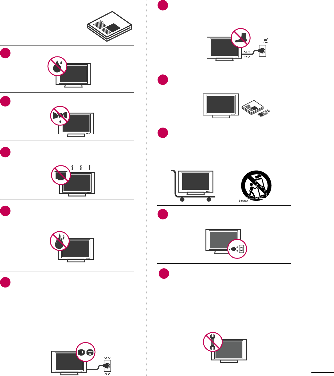
Do not use this apparatus near water.
Clean only with dry cloth.
Do not block any ventilation openings. Install in
accordance with the manufacturer’s instructions.
Do not install near any heat sources such as
radiators, heat registers, stoves, or other
apparatus (including amplifiers) that produce
heat.
Do not defeat the safety purpose of the polarized
or grounding-type plug. A polarized plug has
two blades with one wider than the other. A
grounding type plug has two blades and a
third grounding prong, The wide blade or the
third prong are provided for your safety. If the
provided plug does not fit into your outlet,
consult an electrician for replacement of the
obsolete outlet.
Protect the power cord from being walked on
or pinched particularly at plugs, convenience
receptacles, and the point where they exit from
the apparatus.
Only use attachments/accessories specified by
the manufacturer.
Use only with the cart, stand, tripod, bracket,
or table specified by the manufacturer, or sold
with the apparatus. When a cart is used, use
caution when moving the cart/apparatus com-
bination to avoid injury from tip-over.
Unplug this apparatus during lighting storms
or when unused for long periods of time.
Refer all servicing to qualified service personnel.
Servicing is required when the apparatus has
been damaged in any way, such as power-
supply cord or plug is damaged, liquid has
been spilled or objects have fallen into the
apparatus, the apparatus has been exposed to
rain or moisture, does not operate normally, or
has been dropped.
1
2
3
4
5
7
8
6
9
10
4
SAFETY INSTRUCTIONS
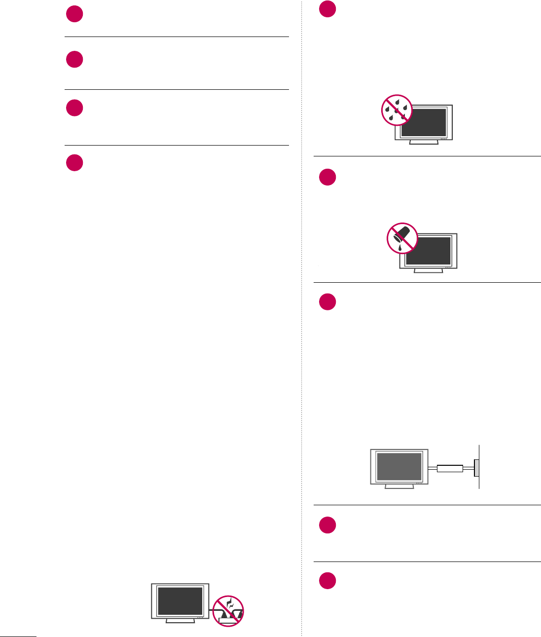
Never touch this apparatus or antenna during
a thunder or lighting storm.
When mounting a TV on the wall, make sure
not to install the TV by the hanging power and
signal cables on the back of the TV.
Do not allow an impact shock or any objects to
fall into the product, and do not drop onto the
screen with something.
CAUTION concerning the Power Cord:
It is recommend that appliances be placed
upon a dedicated circuit; that is, a single
outlet circuit which powers only that appliance
and has no additional outlets or branch
circuits. Check the specification page of this
owner's manual to be certain.
Do not connect too many appliances to the
same AC power outlet as this could result in
fire or electric shock.
Do not overload wall outlets. Overloaded wall
outlets, loose or damaged wall outlets, extension
cords, frayed power cords, or damaged or
cracked wire insulation are dangerous. Any of
these conditions could result in electric shock
or fire. Periodically examine the cord of your
appliance, and if its appearance indicates damage
or deterioration, unplug it, discontinue use of
the appliance, and have the cord replaced with
an exact replacement part by an authorized
servicer. Protect the power cord from physical
or mechanical abuse, such as being twisted,
kinked, pinched, closed in a door, or walked
upon. Pay particular attention to plugs, wall
outlets, and the point where the cord exits the
appliance.
Do not make the TV with the power cord
plugged in. Do not use a damaged or loose
power cord. Be sure do grasp the plug when
unplugging the power cord. Do not pull on the
power cord to unplug the TV.
WARNING - To reduce the risk of fire or electrical
shock, do not expose this product to rain,
moisture or other liquids. Do not touch the TV
with wet hands. Do not install this product
near flammable objects such as gasoline or
candles or expose the TV to direct air
conditioning.
Do not expose to dripping or splashing and do
not place objects filled with liquids, such as
vases, cups, etc. on or over the apparatus (e.g.
on shelves above the unit).
GROUNDING
Ensure that you connect the earth ground wire
to prevent possible electric shock (i.e. a TV
with a three-prong grounded AC plug must be
connected to a three-prong grounded AC out-
let). If grounding methods are not possible,
have a qualified electrician install a separate
circuit breaker.
Do not try to ground the unit by connecting it
to telephone wires, lightening rods, or gas
pipes.
DISCONNECTING DEVICE FROM MAINS
Mains plug is the disconnecting device. The
plug must remain readily operable.
As long as this unit is connected to the AC wall
outlet, it is not disconnected from the AC
power source even if you turn off this unit by
SWITCH.
12
11
14
13
16
17
18
19
Power
Supply
Short-circuit
Breaker
15
5
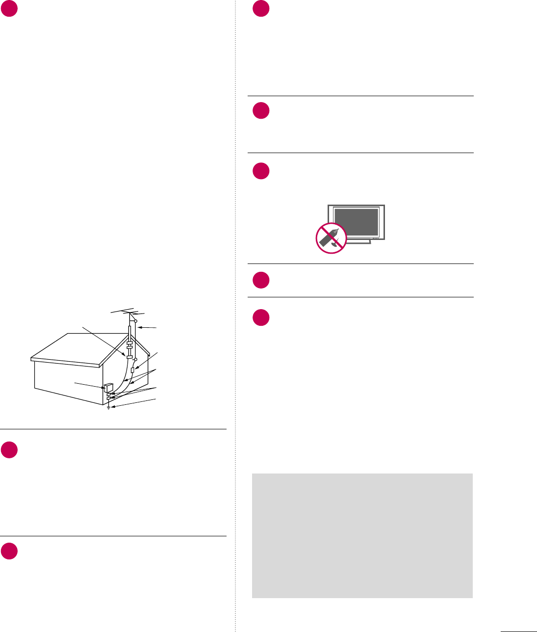
ANTENNAS
Outdoor antenna grounding
If an outdoor antenna is installed, follow the
precautions below. An outdoor antenna system
should not be located in the vicinity of over-
head power lines or other electric light or
power circuits, or where it can come in contact
with such power lines or circuits as death or
serious injury can occur.
Be sure the antenna system is grounded so as
to provide some protection against voltage
surges and built-up static charges.
Section 810 of the National Electrical Code
(NEC) in the U.S.A. provides information with
respect to proper grounding of the mast and
supporting structure, grounding of the lead-in
wire to an antenna discharge unit, size of
grounding conductors, location of antenna dis-
charge unit, connection to grounding elec-
trodes and requirements for the grounding
electrode.
Antenna grounding according to the
National Electrical Code, ANSI/NFPA 70
Cleaning
When cleaning, unplug the power cord and
scrub gently with a soft cloth to prevent
scratching. Do not spray water or other liquids
directly on the TV as electric shock may occur.
Do not clean with chemicals such as alcohol,
thinners or benzene.
Moving
Make sure the product is turned off,
unplugged and all cables have been removed. It
may take 2 or more people to carry larger TVs.
Do not press against or put stress on the front
panel of the TV.
Ventilation
Install your TV where there is proper ventila-
tion. Do not install in a confined space such as
a bookcase. Do not cover the product with
cloth or other materials (e.g.) plastic while
plugged in. Do not install in excessively dusty
places.
If you smell smoke or other odors coming from
the TV or hear strange sounds, unplug the power
cord contact an authorized service center.
Do not press strongly upon the panel with
hand or sharp object such as nail, pencil or
pen, or make a scratch on it.
Keep the product away from direct sunlight.
For LCD TV
If the TV feels cold to the touch, there may be
a small “flicker” when it is turned on. This is
normal, there is nothing wrong with TV.
Some minute dot defects may be visible on the
screen, appearing as tiny red, green, or blue
spots. However, they have no adverse effect on
the monitor's performance.
Avoid touching the LCD screen or holding your
finger(s) against it for long periods of time.
Doing so may produce some temporary dis-
tortion effects on the screen.
20 23
24
25
26
27
21
22
Antenna Lead in Wire
Antenna Discharge Unit
(NEC Section 810-20)
Grounding Conductor
(NEC Section 810-21)
Ground Clamps
Power Service Grounding
Electrode System (NEC
Art 250, Part H)
Ground Clamp
Electric Service
Equipment
NEC: National Electrical Code
ON DISPOSAL
(Only Hg lamp used LCD TV)
The fluorescent lamp used in this product contains
a small amount of mercury. Do not dispose of
this product with general household waste.
Disposal of this product must be carried out in
accordance to the regulations of your local authority.

6
CONTENTS
WARNING / CAUTION
. . . . . . . . . . . . . . . . . . . . . . . . . . . . 2
SAFETY INSTRUCTIONS
. . . . . . . . . . . . . . . . . . . . . . . . . . 3
FEATURE OF THIS TV
. . . . . . . . . . . . . . . . . . . . . . . . . . . . . . . 8
PREPARATION
Accessories . . . . . . . . . . . . . . . . . . . . . . . . . . . . . . . . . . . . . . . . . . . . . . . . . . . . . . 9
Front Panel Information . . . . . . . . . . . . . . . . . . . . . . . . . . . . . . . . . . . 10
Back Panel Information . . . . . . . . . . . . . . . . . . . . . . . . . . . . . . . . . . . . 12
Stand Instruction . . . . . . . . . . . . . . . . . . . . . . . . . . . . . . . . . . . . . . . . . . . . . 14
VESA Wall Mounting . . . . . . . . . . . . . . . . . . . . . . . . . . . . . . . . . . . . . . . . 18
Cable Management . . . . . . . . . . . . . . . . . . . . . . . . . . . . . . . . . . . . . . . . . 19
Desktop Pedestal Installation . . . . . . . . . . . . . . . . . . . . . . . . . . . 21
Swivel Stand . . . . . . . . . . . . . . . . . . . . . . . . . . . . . . . . . . . . . . . . . . . . . . . . . . . . 21
Attaching the TV to a Desk . . . . . . . . . . . . . . . . . . . . . . . . . . . . . . 22
Kensington Security System . . . . . . . . . . . . . . . . . . . . . . . . . . . . . 22
Securing the TV to the wall to prevent falling when
the TV is used on a stand . . . . . . . . . . . . . . . . . . . . . . . . . . . . . . . . 23
Antenna or Cable Connection . . . . . . . . . . . . . . . . . . . . . . . . . . 24
EXTERNAL EQUIPMENT SETUP
HD Receiver Setup . . . . . . . . . . . . . . . . . . . . . . . . . . . . . . . . . . . . . . . . . 25
DVD Setup . . . . . . . . . . . . . . . . . . . . . . . . . . . . . . . . . . . . . . . . . . . . . . . . . . . . . 28
VCR Setup . . . . . . . . . . . . . . . . . . . . . . . . . . . . . . . . . . . . . . . . . . . . . . . . . . . . . 30
Other A/V Source Setup . . . . . . . . . . . . . . . . . . . . . . . . . . . . . . . . . 32
PC Setup . . . . . . . . . . . . . . . . . . . . . . . . . . . . . . . . . . . . . . . . . . . . . . . . . . . . . . . . 33
USB Connection . . . . . . . . . . . . . . . . . . . . . . . . . . . . . . . . . . . . . . . . . . . . . 40
Audio out Connection . . . . . . . . . . . . . . . . . . . . . . . . . . . . . . . . . . . . . 41
WATCHING TV / CHANNEL CONTROL
Remote Control Functions . . . . . . . . . . . . . . . . . . . . . . . . . . . . . . . 42
Turning On TV . . . . . . . . . . . . . . . . . . . . . . . . . . . . . . . . . . . . . . . . . . . . . . . . 44
Channel Selection . . . . . . . . . . . . . . . . . . . . . . . . . . . . . . . . . . . . . . . . . . . 44
Volume Adjustment . . . . . . . . . . . . . . . . . . . . . . . . . . . . . . . . . . . . . . . . . 44
Initial Setting . . . . . . . . . . . . . . . . . . . . . . . . . . . . . . . . . . . . . . . . . . . . . . . . . . 45
On-Screen Menus Selection . . . . . . . . . . . . . . . . . . . . . . . . . . . . 46
Quick Menu . . . . . . . . . . . . . . . . . . . . . . . . . . . . . . . . . . . . . . . . . . . . . . . . . . . . 47
Channel Setup
- Auto Scan (Auto Tuning) . . . . . . . . . . . . . . . . . . . . . . . . . . . 48
- Add / Delete Channel (Manual Tuning) . . . . . . 49
- Channel Editing . . . . . . . . . . . . . . . . . . . . . . . . . . . . . . . . . . . . . . . . 50
Channel List . . . . . . . . . . . . . . . . . . . . . . . . . . . . . . . . . . . . . . . . . . . . . . . . . . . . 51
Favorite Channel Setup / Favorite Channel List . . 52
Brief Information . . . . . . . . . . . . . . . . . . . . . . . . . . . . . . . . . . . . . . . . . . . . . 53
Input List . . . . . . . . . . . . . . . . . . . . . . . . . . . . . . . . . . . . . . . . . . . . . . . . . . . . . . . . 54
Input Label . . . . . . . . . . . . . . . . . . . . . . . . . . . . . . . . . . . . . . . . . . . . . . . . . . . . . 55
AV Mode . . . . . . . . . . . . . . . . . . . . . . . . . . . . . . . . . . . . . . . . . . . . . . . . . . . . . . . . 56
Simple Manual . . . . . . . . . . . . . . . . . . . . . . . . . . . . . . . . . . . . . . . . . . . . . . . . 56
Key Lock . . . . . . . . . . . . . . . . . . . . . . . . . . . . . . . . . . . . . . . . . . . . . . . . . . . . . . . . . 57
SIMPLINK . . . . . . . . . . . . . . . . . . . . . . . . . . . . . . . . . . . . . . . . . . . . . . . . . . . . . . . 58
USB
Entry Modes . . . . . . . . . . . . . . . . . . . . . . . . . . . . . . . . . . . . . . . . . . . . . . . . . . . 60
Photo List . . . . . . . . . . . . . . . . . . . . . . . . . . . . . . . . . . . . . . . . . . . . . . . . . . . . . . . 61
Music List . . . . . . . . . . . . . . . . . . . . . . . . . . . . . . . . . . . . . . . . . . . . . . . . . . . . . . . 65
PICTURE CONTROL
Picture Size (Aspect Ratio) Control . . . . . . . . . . . . . . . . . . 68
Picture Wizard . . . . . . . . . . . . . . . . . . . . . . . . . . . . . . . . . . . . . . . . . . . . . . . . . 70
Preset Picture Settings (Picture Mode) . . . . . . . . . . . . . 72
Manual Picture Adjustment - User Mode . . . . . . . . . . 73
Picture Improvement Technology . . . . . . . . . . . . . . . . . . . . . 74
Expert Picture Control . . . . . . . . . . . . . . . . . . . . . . . . . . . . . . . . . . . . . 75
Energy Saving . . . . . . . . . . . . . . . . . . . . . . . . . . . . . . . . . . . . . . . . . . . . . . . . . 78
Picture Reset . . . . . . . . . . . . . . . . . . . . . . . . . . . . . . . . . . . . . . . . . . . . . . . . . 79
Power Indicator . . . . . . . . . . . . . . . . . . . . . . . . . . . . . . . . . . . . . . . . . . . . . . 80
Demo Mode . . . . . . . . . . . . . . . . . . . . . . . . . . . . . . . . . . . . . . . . . . . . . . . . . . . . 81

7
SOUND & LANGUAGE CONTROL
Auto Volume Leveler (Auto Volume) . . . . . . . . . . . . . . . . . 82
Clear Voice II . . . . . . . . . . . . . . . . . . . . . . . . . . . . . . . . . . . . . . . . . . . . . . . . . . 83
Preset Sound Setting (Sound Mode) . . . . . . . . . . . . . . . . 84
Sound Setting Adjustment - User Mode . . . . . . . . . . . 85
Balance . . . . . . . . . . . . . . . . . . . . . . . . . . . . . . . . . . . . . . . . . . . . . . . . . . . . . . . . . . 86
TV Speakers On/Off Setup . . . . . . . . . . . . . . . . . . . . . . . . . . . . . 87
Audio Reset . . . . . . . . . . . . . . . . . . . . . . . . . . . . . . . . . . . . . . . . . . . . . . . . . . . 88
Stereo/SAP Broadcasts Setup . . . . . . . . . . . . . . . . . . . . . . . . . . 89
Audio Language . . . . . . . . . . . . . . . . . . . . . . . . . . . . . . . . . . . . . . . . . . . . . . 90
On-Screen Menus Language Selection . . . . . . . . . . . . . . 91
Caption Mode
- Analog Broadcasting System Captions . . . . . . . 92
- Digital Broadcasting System Captions . . . . . . . . 93
- Caption Option . . . . . . . . . . . . . . . . . . . . . . . . . . . . . . . . . . . . . . . 94
TIME SETTING
Clock Setting
- Auto Clock Setup . . . . . . . . . . . . . . . . . . . . . . . . . . . . . . . . . . . . 95
- Manual Clock Setup . . . . . . . . . . . . . . . . . . . . . . . . . . . . . . . . . 96
Auto On/Off Time Setting . . . . . . . . . . . . . . . . . . . . . . . . . . . . . . 97
Sleep Timer Setting . . . . . . . . . . . . . . . . . . . . . . . . . . . . . . . . . . . . . . . . . 98
PARENTAL CONTROL / RATINGS
Set Password & Lock System . . . . . . . . . . . . . . . . . . . . . . . . . . . 99
Channel Blocking . . . . . . . . . . . . . . . . . . . . . . . . . . . . . . . . . . . . . . . . . . . 102
Movie & TV Rating . . . . . . . . . . . . . . . . . . . . . . . . . . . . . . . . . . . . . . . . 103
Downloadable Rating . . . . . . . . . . . . . . . . . . . . . . . . . . . . . . . . . . . . . 10 8
External Input Blocking . . . . . . . . . . . . . . . . . . . . . . . . . . . . . . . . . . 109
APPENDIX
Troubleshooting . . . . . . . . . . . . . . . . . . . . . . . . . . . . . . . . . . . . . . . . . . . . . 110
Maintenance . . . . . . . . . . . . . . . . . . . . . . . . . . . . . . . . . . . . . . . . . . . . . . . . . . 112
Product Specifications . . . . . . . . . . . . . . . . . . . . . . . . . . . . . . . . . . . . 113
IR Codes . . . . . . . . . . . . . . . . . . . . . . . . . . . . . . . . . . . . . . . . . . . . . . . . . . . . . . . 115
External Control Through RS-232C . . . . . . . . . . . . . . . . .116
Open Source License . . . . . . . . . . . . . . . . . . . . . . . . . . . . . . . . . . . . . .122
8
FEATURE OF THIS TV
■
When a fixed image (e.g. logos, screen menus, video game, and computer display) is displayed on the TV
for an extended period, it can become permanently imprinted on the screen. This phenomenon is known
as “image burn” or “burn-in.” Image burn is not covered under the manufacturer’s warranty.
■
In order to prevent image burn, avoid displaying a fixed image on your TV screen for a prolonged period
(2 or more hours for LCD, 1 or more hours for Plasma).
■
Image burn can also occur on the letterboxed
areas of your TV if you use the 4:3 aspect
ratio setting for an extended period.
IMPORTANT INFORMATION TO PREVENT “IMAGE BURN
/ BURN-IN” ON YOUR TV SCREEN
The AV Mode optimizes the picture into Cinema,
Sports, and game Mode according to the video and
audio content. The viewer has the ability to quickly
choose the correct mode for the picture they are
viewing.
Displays HDTV programs in full 1920 x 1080p resolu-
tion for a more detailed picture.
Automatically enhances and amplifies the sound of
human voice frequency range to help keep dialogue
audible when background noise swells.
LG TV include a unique invisible speaker system,
tuned by renowned audio expert, Mr. Mark Levinson.
Speakers are embedded in strategic spots behind the
front cabinet and use minute vibrations to turn the
entire front bezel into the speaker system. The result
is a clean, polished look, and enhanced audio by
increasing the “sweet spot”, giving a wider and richer
sound field.
HDMITM, the HDMI logo and High-Definition
Multimedia Interface are trademarks or registered
trademarks of HDMI Licensing."
is a trademark of SRS Labs, Inc.
TruSurround XT technology is incorporated under
license from SRS Labs, Inc.
Manufactured under license from Dolby Laboratories.
“
Dolby
“and the double-D symbol are trademarks of
Dolby Laboratories.
This TV contains the detailed calibrations necessary
for professional certification by the Imaging Science
Foundation. The resulting ISF “day” and “night” modes
will then be accessible by the user to experience the
best their LG HDTV has to offer.
CALIBRATE LIKE A PRO: Sophisticated and detailed
calibrations can be made through the ISFccc mode.
Detailed calibration requires a licensed technician.
Please contact your local dealer to inquire about an
ISF certified technician.
High-definition television. High-resolution digital
television broadcast and playback system composed
of roughly a million or more pixels, 16:9 aspect-ratio
screens, and AC3 digital audio. A subset of digital
television, HDTV formats include 1080i and 720p
resolutions.
THX (Thomlinson Holman’s Experiment) is the audio
and video certification standard of THX established
by George Lucas, who directed the movie Star Wars,
and Thomlinson.
This is the product to be certified in THX display area
and guarantees screen quality that exceeds the display
standard specification in both hardware and software.
PREPARATION
9
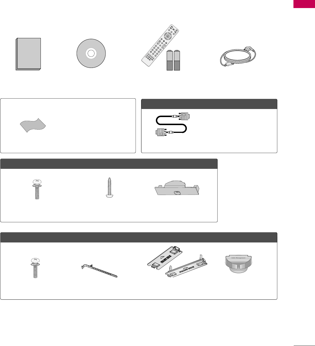
ACCESSORIES
PREPARATION
Ensure that the following accessories are included with your TV. If an accessory is missing, please contact the
dealer where you purchased the TV.
The accessories included may differ from the images below.
1.5V 1.5V
Owner’s Manual Power Cord
Remote Control,
Batteries
FAV
MARK
AVMODE
POWER
Q.MENUMENU
WIDGETS
RETURN
NETCAST
VOLCH
123
456
78
0
9
FLASHBK
P
A
G
E
INPUT
ENERGYSAVING
LIST
ENTER
INFO
CHAR/NUM
DELETE
MUTE
ABCDEF
GHI
WXYZ
TUV
PQRS
MNO
JKL
RATIO
FREEZE
CD Manual
Option Extras
* Wipe spots on the exterior only with
the polishing cloth.
* Do not wipe roughly when removing
stain. Excessive pressure may cause
scratch or discoloration.
Polishing Cloth
Not included with all models
D-sub 15 pin Cable
When using the VGA (D-sub 15 pin
cable) PC connection, the user
must use shielded signal interface
cables with ferrite cores to maintain
standards compliance.
LCD TV models
Bolts for stand assembly
(Refer to P.16)
Screw for stand fixing
(Refer to P.22)
Protection Cover
(Refer to P.17)
x 4
Plasma TV models
Protection Cover
(Refer to p.15)
or
Cable management clip
(Refer to p.19)
Cable Holder
(Refer to p.19)
x 2x 4
Bolts for stand assembly
(Refer to P.14)
(For 50PS80)
(For 42LH50)
PREPARATION
10
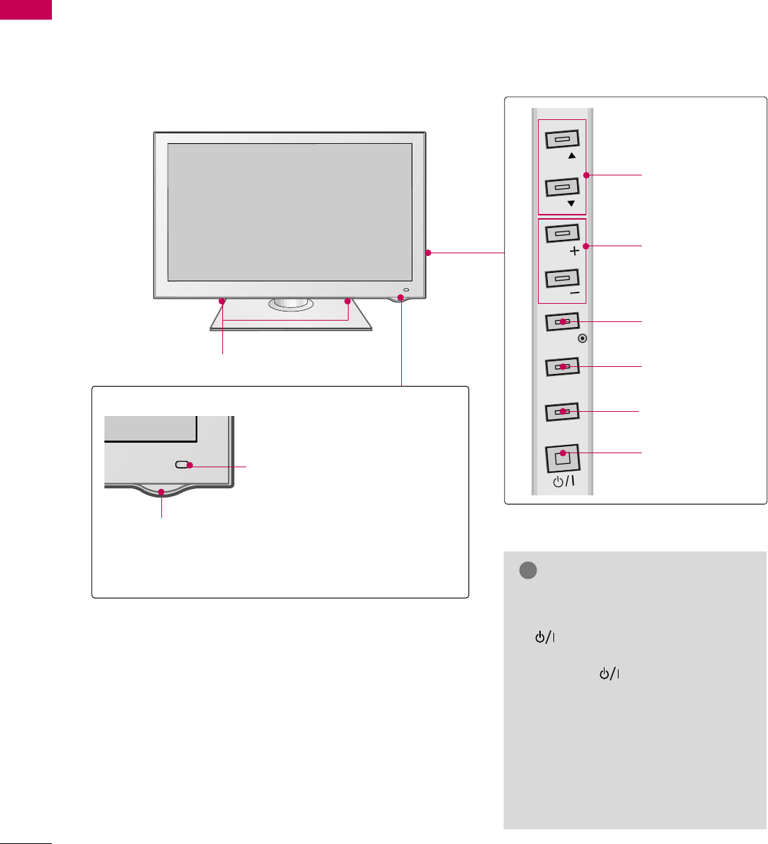
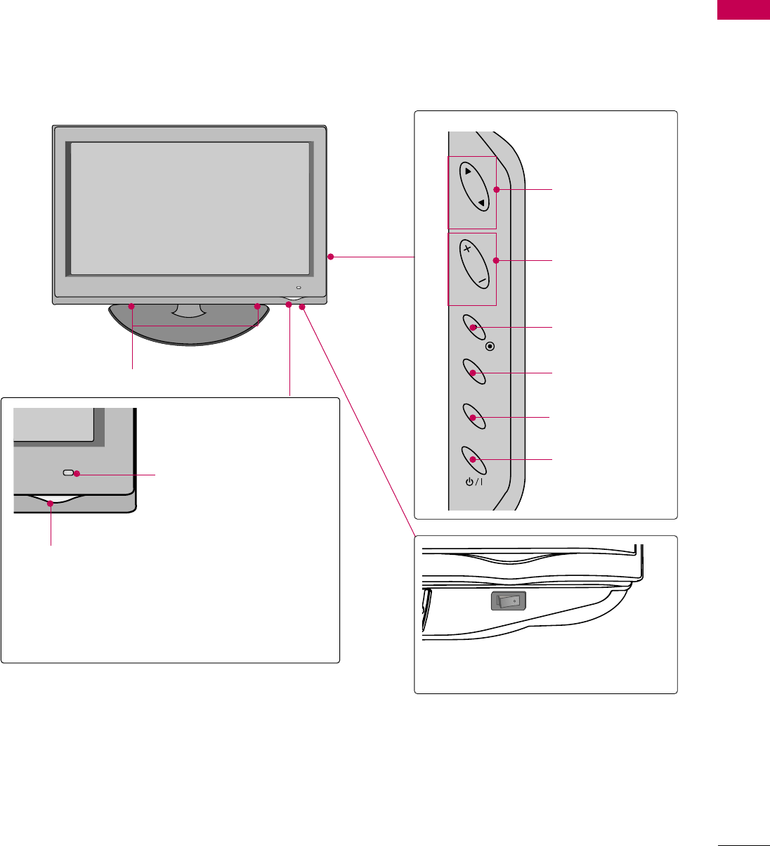
FRONT PANEL INFORMATION
PREPARATION
■
Image shown may differ from your TV.
Plasma TV
SPEAKER
Power/Standby Indicator
Illuminates red in standby mode.
The LED is off while the TV remains on.
Remote Control Sensor,
Intelligent Sensor
Adjusts picture according to the
surrounding conditions
CH
VOL
MENU
INPUT
ENTER
CH
VOL
CHANNEL (DD,E)
Buttons
VOLUME (+, -)
Buttons
ENTER Button
MENU Button
INPUT Button
POWER Button
GWhen the TV cannot be turned on
with the remote control, press the
(POWER) button on the TV
(The remote control will not work
when the (POWER) button on
the TV is switched off).
GDo not step on the glass stand or
subject it to any impact. It may break,
causing possible injury from frag-
ments of glass, or the TV may fall.
GDo not drag the TV. The floor or the
product may be damaged.
NOTE
!
PREPARATION
11
INPUT
MENU
ENTER
CH
VOL
CHANNEL (D,E)
Buttons
VOLUME (+, -)
Buttons
ENTER Button
MENU Button
INPUT Button
POWER Button
Power/Standby Indicator
Illuminates red in standby mode.
Illuminates blue when the TV is switched on.
(Can be adjusted Power Indicator in the
OPTION menu. Gp.?)
Remote Control Sensor,
Intelligent Sensor
Adjusts picture according to
the surrounding conditions
LCD TV
AC power control switch
OFF ON
SPEAKER
PREPARATION
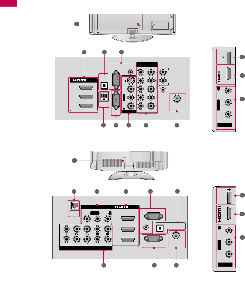
12
BACK PANEL INFORMATION
PREPARATION
■
Image shown may differ from your TV.
10
VIDEO
AUDIO
L R
SERVICE ONLY
AUDIO IN
(RGB/DVI)
OPTICAL DIGITAL
AUDIO OUT
ANTENNA/
CABLE IN
RGB IN (PC)
AV IN 1
COMPONENT IN
2
3
1
2
1
MONO
( )
AUDIOVIDEOLAN
/DVI IN
LR
2 3
7 68
AV IN 2
L/MONO
R
AUDIO
VIDEO
USB IN
IN 4
2
9
3
5
10
1
2
1
3
/DVI IN
COMPONENT IN
ANTENNA/
CABLE IN
OPTICAL
DIGITAL
AUDIO OUT
RGB IN (PC)
LAN
SERVICE
ONLY
AUDIO IN
(RGB/DVI)
AUDIO OUT
REMOTE
CONTROL IN
VIDEO
AUDIO
12
LYPBPRR
AUDIOVIDEOS-VIDEO
MONO
( )
L R
AV IN 1
3
681 7 2
AV IN 2
L/MONO
R
AUDIO
VIDEO
USB IN
IN 4
2
9
3
Plasma TV
LCD TV
5 4
4

PREPARATION
13
LAN
Connects a network with an always on broadband
connection.
AV (Audio/Video) IN
Analog composite connection. Supports standard
definition video only (480i).
HDMI/DVI IN, HDMI IN
Digital Connection.
Supports HD video and Digital audio. Doesn’t
support 480i.
Accepts DVI video using an adapter or HDMI to
DVI cable (not included).
RGB IN (PC)
Analog PC Connection. Uses a D-sub 15 pin cable
(VGA cable).
AUDIO IN (RGB/DVI)
1/8" (0.32 cm) headphone jack for analog PC
audio input.
OPTICAL DIGITAL AUDIO OUT
Digital optical audio output for use with amps and
home theater systems.
Note: In standby mode, this port doesn’t work.
ANTENNA/CABLE IN
Connect over-the air signals to this jack.
Connect cable signals to this jack.
SERVICE ONLY PORT
Used by third party devices.
COMPONENT IN
Analog Connection.
Supports HD.
Uses a red, green, and blue cable for video & red
and white for audio.
USB INPUT
Used for viewing photos and listening to MP3s.
Power Cord Socket
For operation with AC power.
Caution: Never attempt to operate the TV on DC
power.
1
2
3
4
5
8
9
7
6
10
PREPARATION
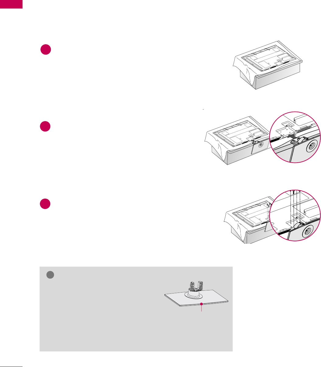
14
STAND INSTRUCTION
PREPARATION
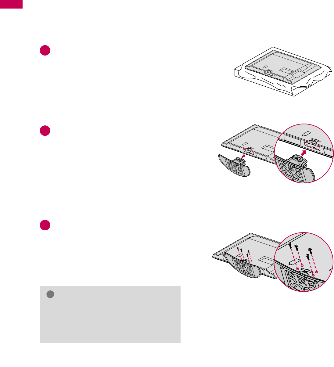
Assemble the TV as shown.
2
Fix the 4 bolts securely using the holes in the
back of the TV.
3
Carefully place the TV screen side down on a
cushioned surface to protect the screen from
damage.
1
INSTALLATION (
For 50PS80)
■
Image shown may differ from your TV.
GWhen assembling the stand, make sure to
distinguish and assemble the front and
rear side of the stand correctly.
GWhen assembling the desk type stand,
make sure the bolt is fully tightened (If
not tightened fully, the TV can tilt forward after
the product installation). Do not over tighten.
NOTE
!
Front
Plasma TV
PREPARATION
15
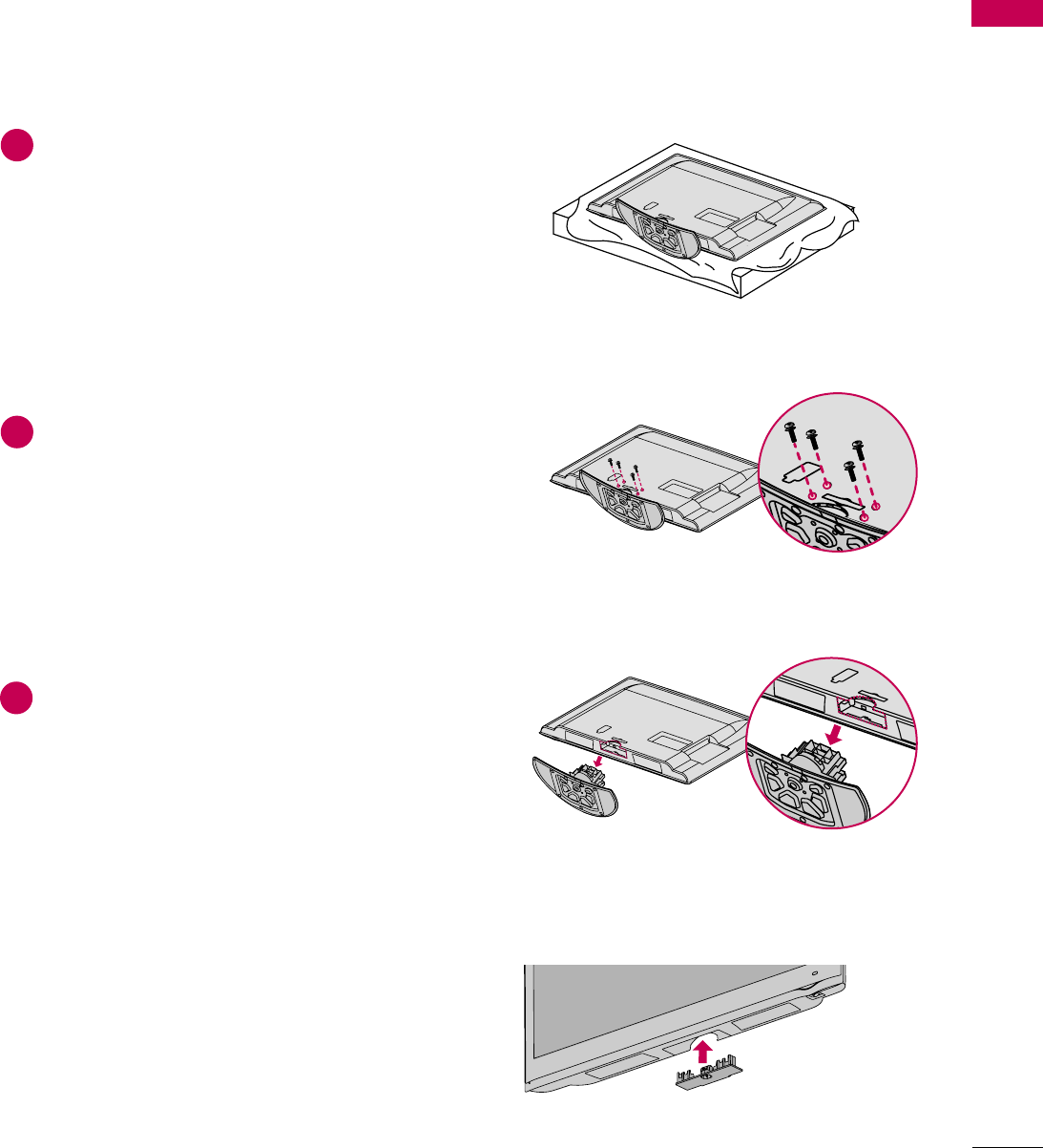
DETACHMENT
Carefully place the TV screen side down on a
cushioned surface to protect the screen from
damage.
1
Loose the bolts from TV.
2
Detach the stand from TV.
3
After removing the stand, install the included
protection cover over the hole for the stand.
Press the PROTECTION COVER into the TV
until you hear it click.
PROTECTION COVER
PREPARATION
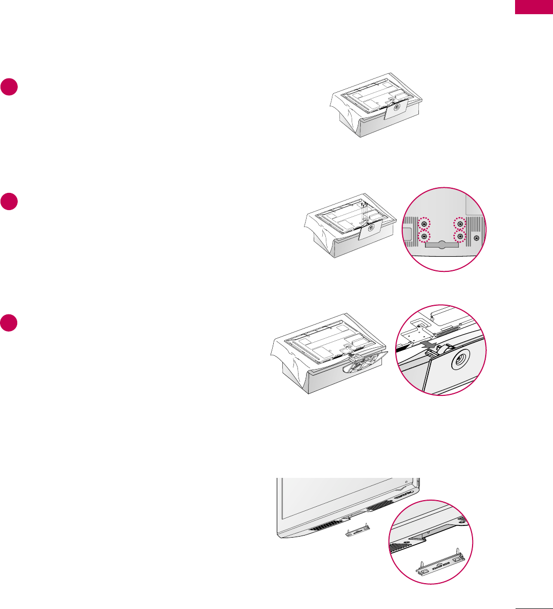
16
STAND INSTRUCTION
PREPARATION
■
Image shown may differ from your TV.
Carefully place the TV screen side down on a
cushioned surface to protect the screen from
damage.
Assemble the TV as shown.
Fix the 4 bolts securely using the holes in the
back of the TV.
1
2
3
INSTALLATION
GWhen assembling the desk type stand, make sure
the bolt is fully tightened (If not tightened fully,
the TV can tilt forward after the product installa-
tion). Do not over tighten.
NOTE
!
LCD TV
PREPARATION
17
DETACHMENT
Carefully place the TV screen side down on a
cushioned surface to protect the screen from
damage.
1
Loose the bolts from TV.
2
Detach the stand from TV.
3
After removing the stand, install the included
protection cover over the hole for the stand.
Press the PROTECTION COVER into the TV
until you hear it click.
PROTECTION COVER
PREPARATION
18
VESA WALL MOUNTING
PREPARATION
Install your wall mount on a solid wall perpendicular to the floor. When attaching to other building materials, please
contact your nearest installer.
If installed on a ceiling or slanted wall, it may fall and result in severe personal injury.
We recommend that you use an LG brand wall mount when mounting the TV to a wall.
LG recommends that wall mounting be performed by a qualified professional installer.
GDo not install your wall mount kit while your TV is turned on. It may result in personal
injury due to electric shock.
CAUTION
GScrew length needed depends on the wall mount
used. For further information, refer to the instruc-
tions included with the mount.
GStandard dimensions for wall mount kits are shown
in the table.
GWhen purchasing our wall mount kit, a detailed
installation manual and all parts necessary for
assembly are provided.
GDo not use screws longer then the standard dimen-
sion, as they may cause damage to the inside to
the TV.
GFor wall mounts that do not comply with the VESA
standard screw specifications, the length of the
screws may differ depending on their specifica-
tions.
GDo not use screws that do not comply with the
VESA standard screw specifications.
Do not use fasten the screws too strongly, this may
damage the TV or cause the TV to a fall, leading to
personal injury. LG is not liable for these kinds of
accidents.
GLG is not liable for TV damage or personal injury
when a non-VESA or non specified wall mount is
used or the consumer fails to follow the TV installa-
tion instructions.
NOTE
!
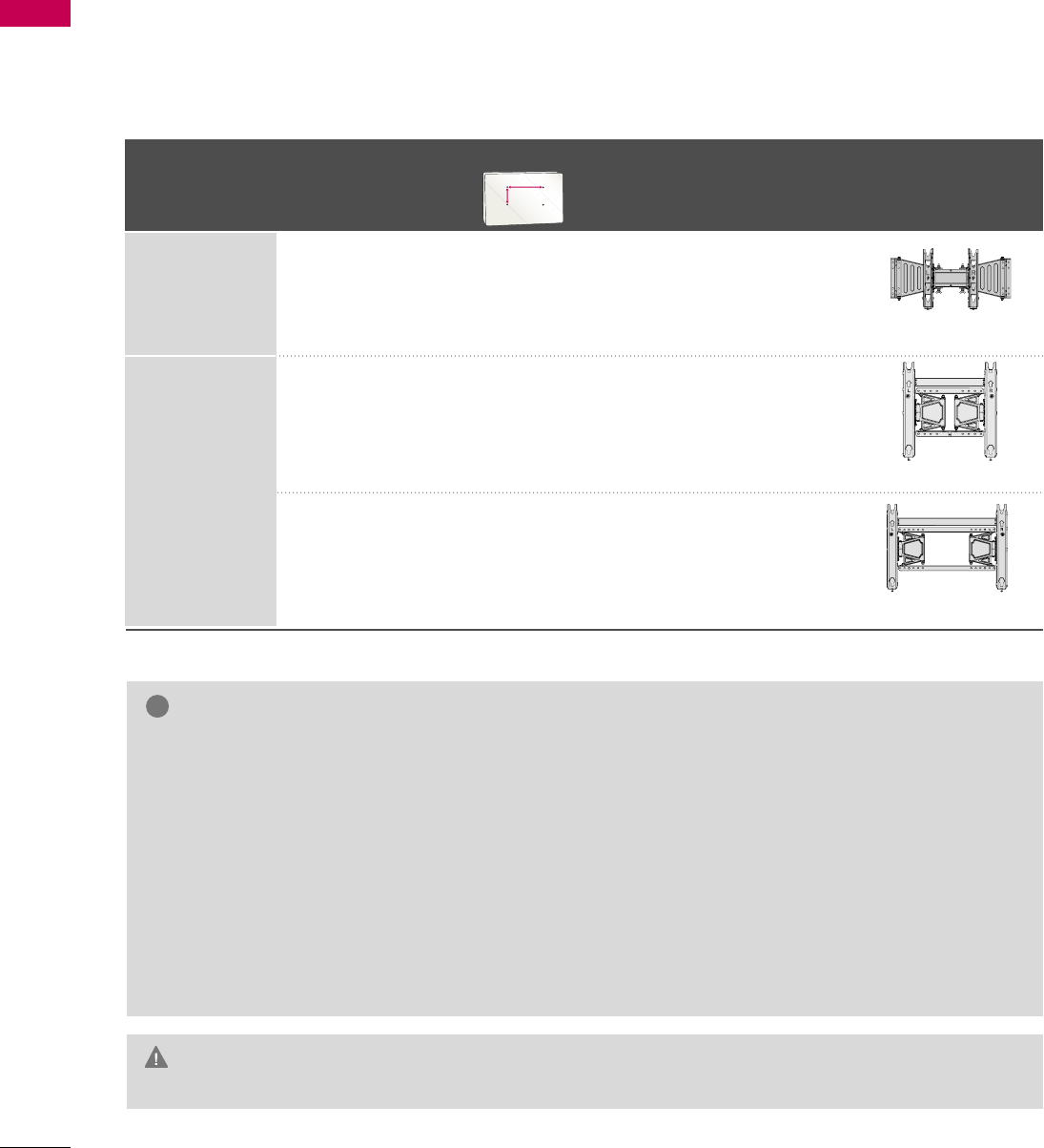
Product
VESA (A *B)
Standard Screw Quantity Wall Mounting Bracket
(sold separately)
LCD TV
PLASMA TV
Model
42LH50
47LH50
60PS80
50PS80
200 * 200 M6 4
400 * 400 M6 4
600 * 400 M8 4
AA
BB
AW-47LG30M
AW-50PG60MS
AW-60PG60MS
PREPARATION
19
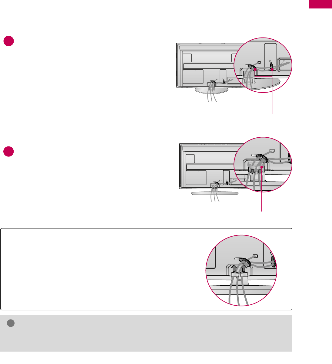
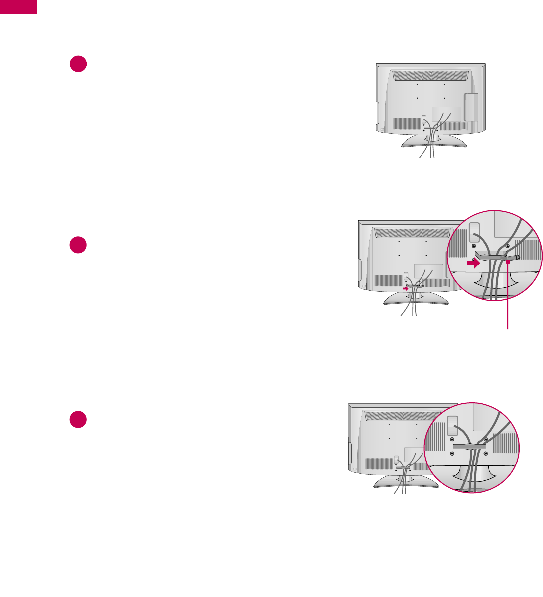
CABLE MANAGEMENT
Connect the cables as necessary.
To connect additional equipment, see the
EXTERNAL EQUIPMENT SETUP section.
If your TV has the CABLE HOLDER, install it
as shown and bundle the cables.
Install the CABLE MANAGEMENT CLIP as
shown.
CABLE MANAGEMENT CLIP
CABLE HOLDER
1
2
Plasma TV
■
Image shown may differ from your TV.
GDo not hold the CABLE MANAGEMENT CLIP when moving the TV.
- If the TV is dropped, you may be injured or the product may be broken.
NOTE
!
How to remove the CABLE MANAGEMENT CLIP
GHold the CABLE MANAGEMENT CLIP with both hands and pull
it upward.
PREPARATION
20
CABLE MANAGEMENT
PREPARATION
Connect the cables as necessary.
To connect additional equipment, see the
EXTERNAL EQUIPMENT SETUP section.
Install the CABLE MANAGEMENT CLIP as
shown.
CABLE MANAGEMENT CLIP
1
2
Put the cables inside the CABLE MANAGEMENT
CLIP and snap it closed.
3
LCD TV
■
Image shown may differ from your TV.
PREPARATION
21
DESKTOP PEDESTAL INSTALLATION
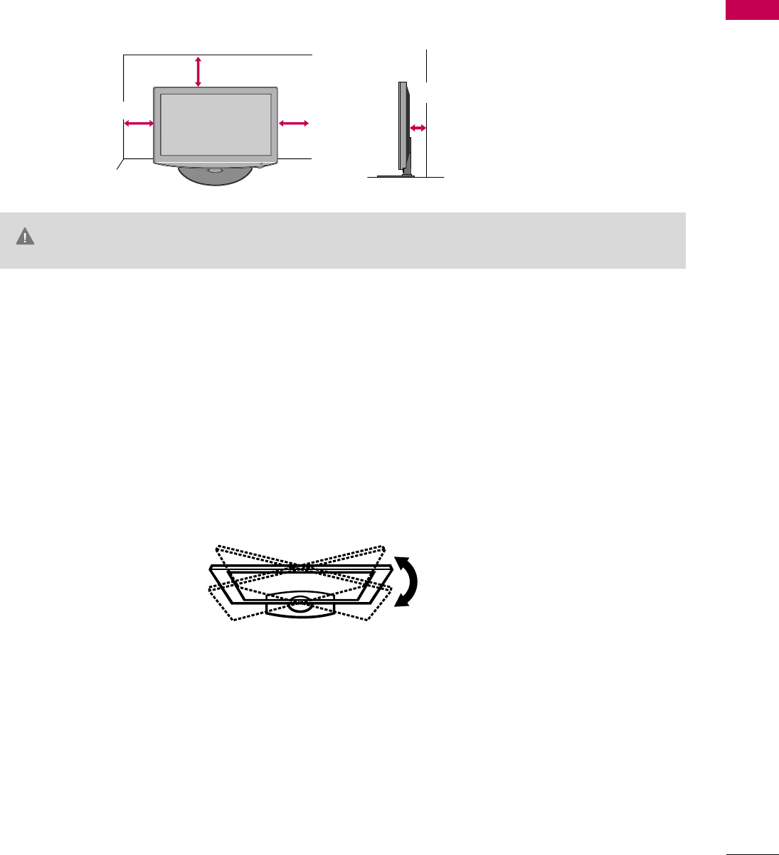
SWIVEL STAND
After installing the TV, you can adjust the TV set manually to the left or right direction by 20 degrees to suit
your viewing position.
For proper ventilation, allow a clearance of 4 inches on all four sides from the wall.
■
Image shown may differ from your TV.
4 inches
GEnsure adequate ventilation by following the clearance recommendations.
GDo not mount near or above any type of heat source.
CAUTION
4 inches
4 inches
4 inches
PREPARATION
22
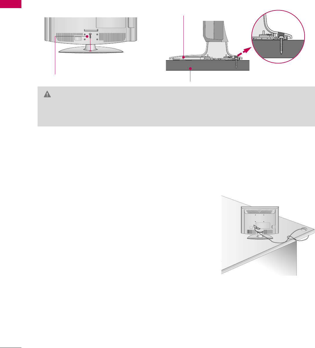
ATTACHING THE TV TO A DESK (For 42LH50)
PREPARATION
The TV must be attached to a desk so it cannot be pulled in a forward/backward direction, potentially causing
injury or damaging the product.
GTo prevent TV from falling over, the TV should be securely attached to the floor/wall per installation
instructions. Tipping, shaking, or rocking the machine may cause injury.
WARNING
1-Screw
(provided as parts of the product)
Desk
Stand
KENSINGTON SECURITY SYSTEM
■
This feature is not available for all models.
- The TV is equipped with a Kensington Security System connector on
the back panel. Connect the Kensington Security System cable as
shown below.
- For the detailed installation and use of the Kensington Security
System, refer to the user’s guide provided with the Kensington
Security System.
For further information, contact http://www.kensington.com,
the internet homepage of the Kensington company. Kensington sells
security systems for expensive electronic equipment such as note-
book PCs and LCD projectors.
NOTE: The Kensington Security System is an optional accessory.
PREPARATION
23
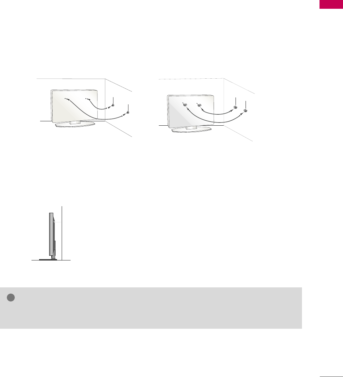
SECURING THE TV TO THE WALL TO PREVENT FALLING
WHEN THE TV IS USED ON A STAND
We recommend that you set up the TV close to a wall so it cannot fall over if pushed backwards.
Additionally, we recommend that the TV be attached to a wall so it cannot be pulled in a forward direction,
potentially causing injury or damaging the product.
Caution: Please make sure that children don’t climb on or hang from the TV.
■Insert the eye-bolts (or TV brackets and bolts) to tighten the product to the wall as shown in the picture.
*If your product has the bolts in the eye-bolts position before inserting the eye-bolts, loosen the bolts.
* Insert the eye-bolts or TV brackets/bolts and tighten them securely in the upper holes.
Secure the wall brackets with the bolts (sold separately) to the wall. Match the height of the bracket that is
mounted on the wall to the holes in the product.
Ensure the eye-bolts or brackets are tightened securely.
■Use a sturdy rope (sold separately) to tie the product. It is safer to tie
the rope so it becomes horizontal between the wall and the product.
■
You should purchase necessary components to prevent the TV from tipping over (when not using a wall mount).
■
Image shown may differ from your TV.
GUse a platform or cabinet strong enough and large enough to support the size and weight of the TV.
GTo use the TV safely make sure that the height of the bracket on the wall and the one on the TV are the same.
NOTE
!
PREPARATION
24
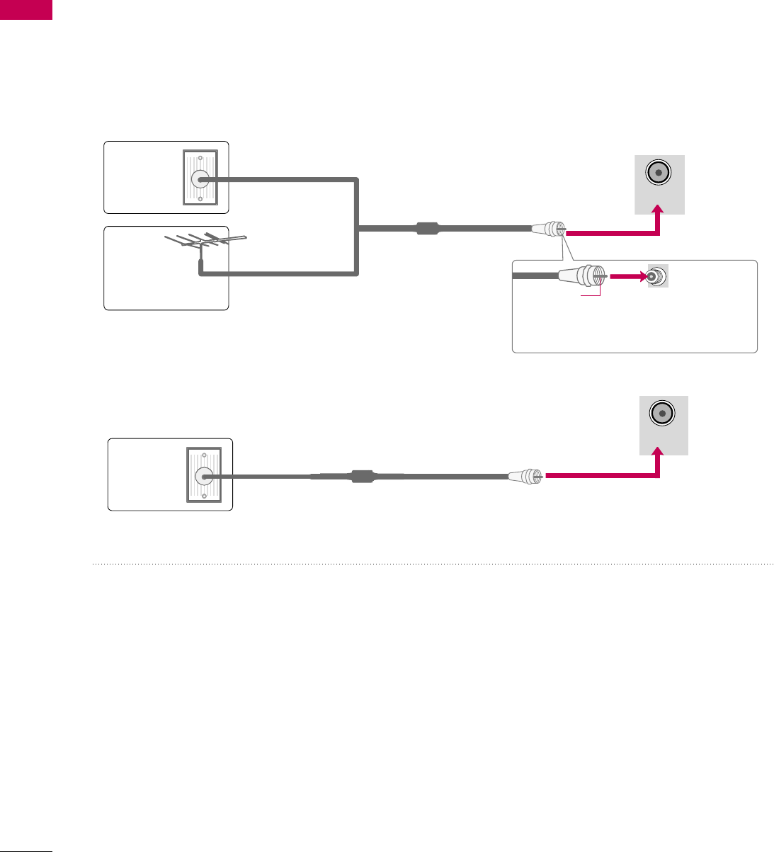
ANTENNA OR CABLE CONNECTION
PREPARATION
■
To prevent damage do not connect to the power outlet until all connections are made between the devices.
■
Image shown may differ from your TV.
1. Antenna (Analog or Digital)
Wall Antenna Socket or Outdoor Antenna without a Cable Box
Connections.
For optimum picture quality, adjust antenna direction if needed.
2. Cable
Wall
Antenna
Socket
Outdoor
Antenna
(VHF, UHF)
Cable TV
Wall Jack
Multi-family Dwellings/Apartments
(Connect to wall antenna socket)
RF Coaxial Wire (75 ohm)
RF Coaxial Wire (75 ohm)
Single-family Dwellings /Houses
(Connect to wall jack for outdoor antenna)
Be careful not to bend the copper wire
when connecting the antenna.
Copper Wire
■To improve the picture quality in a poor signal area, please purchase a signal amplifier and install properly.
■If the antenna needs to be split for two TV’s, install a 2-Way Signal Splitter.
■If the antenna is not installed properly, contact your dealer for assistance.
ANTENNA/
CABLE IN
ANTENNA/
CABLE IN
EXTERNAL EQUIPMENT SETUP
25
EXTERNAL EQUIPMENT SETUP
HD RECEIVER SETUP
This TV can receive digital over-the-air/digital cable signals without an external digital set-top box. However, if
you do receive digital signals from a digital set-top box or other digital external device.
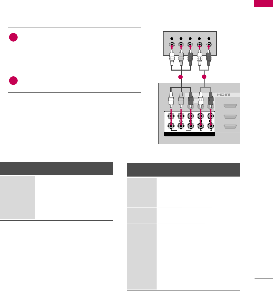
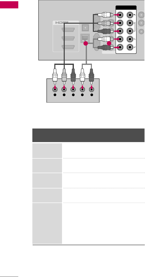
Component Connection
1. How to connect
Connect the video outputs (Y, PB, PR)of the digital set-
top box to the COMPONENT IN VIDEO 1 jacks on
the TV. Match the jack colors (Y = green, PB= blue, and
PR= red).
Connect the audio output of the digital set-top box to
the COMPONENT IN AUDIO 1 jacks on the TV.
2
1
2. How to use
■Turn on the digital set-top box.
(Refer to the owner’s manual for the digital set-top box operation.)
■Select the Component1 input source on the TV using the
INPUT button on the remote control.
■If connected to COMPONENT IN 2 input, select the
Component2 input source on the TV.
■To prevent the equipment damage, never plug in any power cords until you have finished connecting all equipment.
■
Image shown may differ from your TV.
Y, CB/PB, CR/PR
Supported Resolutions
Horizontal Vertical
Frequency(KHz)Frequency(Hz)
15.73 59.94
15.73 60.00
31.47 59.94
31.50 60.00
44.96 59.94
45.00 60.00
33.72 59.94
33.75 60.00
26.97 23.976
27.00 24.00
28.125 25.00
33.71 29.97
33.75 30.00
56.25 50.00
67.432 59.94
67.50 60.00
Resolution
720x480i
720x480p
1280x720p
1920x1080i
1920x1080p
Signal
480i
480p
720p
108 0 i
108 0 p
Component
Yes
Yes
Yes
Yes
Yes
HDMI
No
Yes
Yes
Yes
Yes
AV IN 1
2
3
1
MONO
( )
AUDIOVIDEO L R
/DVI IN
VIDEO
AUDIO
L R
COMPONENT IN
2
1
Y L RPBPR
12
LCD TV
EXTERNAL EQUIPMENT SETUP
26
EXTERNAL EQUIPMENT SETUP
Y, CB/PB, CR/PR
Horizontal Vertical
Frequency(KHz)Frequency(Hz)
15.73 59.94
15.73 60.00
31.47 59.94
31.50 60.00
44.96 59.94
45.00 60.00
33.72 59.94
33.75 60.00
26.97 23.976
27.00 24.00
33.71 29.97
33.75 30.00
67.432 59.94
67.50 60.00
Resolution
720x480i
720x480p
1280x720p
1920x1080i
1920x1080p
2
1
3
/DVI IN
OPTICAL
DIGITAL
AUDIO OUT
RGB IN (PC)
LAN
SERVICE
ONLY
AUDIO IN
(RGB/DVI)
REMOTE
CONTROL
AUDIOVIDEOS-VIDEO
MONO
( )
L R
AV IN 1
COMPONENT IN
VIDEO
AUDIO
12
LYPBPRR
Y L RPBPR
12
Plasma TV
EXTERNAL EQUIPMENT SETUP
27
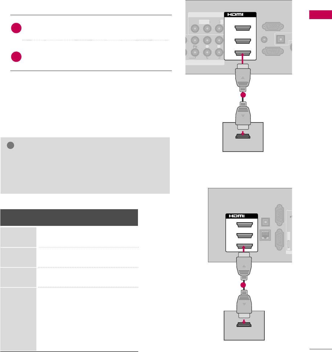
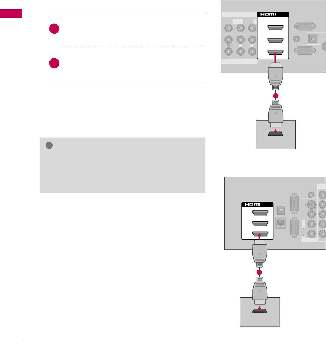
HDMI Connection
Connect the digital set-top box to HDMI/DVI IN 1,
2, 3, or 4 jack on the TV.
No separate audio connection is necessary.
HDMI supports both audio and video.
1. How to connect
2. How to use
■Turn on the digital set-top box.
(Refer to the owner’s manual for the digital set-top box.)
■Select the HDMI1, HDMI2, HDMI3, or HDMI4 input
source on the TV using the INPUT button on the remote
control.
2
1
HDMI-DTV
Horizontal Vertical
Frequency(KHz)Frequency(Hz)
31.47 59.94
31.50 60.00
44.96 59.94
45.00 60.00
33.72 59.94
33.75 60.00
26.97 23.976
27.00 24.00
28.125 25.00
33.71 29.97
33.75 30.00
56.25 50.00
67.432 59.94
67.50 60.00
Resolution
720x480p
1280x720p
1920x1080i
1920x1080p
EO
AUDIO
L R
RS-232C IN
(
CONTROL&SERVICE)
AUDIO IN
(RGB/DVI)
OPT
A
AN
CA
RGB IN (PC)
AV IN 1
OMPONENT IN
1
MONO
( )
AUDIOVIDEO L R
2
3
1
/DVI IN
HDMI OUTPUT
1
OPTICAL
DIGITAL
AUDIO OUT
RGB IN (PC)
LAN
SERVICE
ONLY
AU
(R
AUDIOVIDEOS-VIDEO
MONO
( )
L R
AV
2
1
3
/DVI IN
HDMI OUTPUT
1
GCheck HDMI cable over version 1.3.
If the HDMI cables don’t support HDMI version 1.3, it can
cause flickers or no screen display. In this case use the lat-
est cables that support HDMI version 1.3.
NOTE
!
LCD TV
Plasma TV
EXTERNAL EQUIPMENT SETUP
28
EXTERNAL EQUIPMENT SETUP
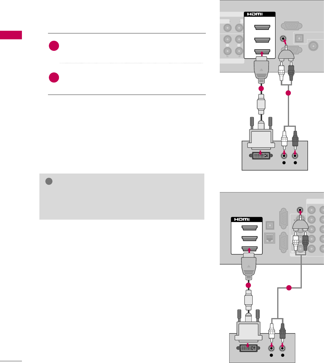
DVI to HDMI Connection
AUDIO
L R
RS-232C IN
(
CONTROL&SERVICE)
OPTICAL DIGITA
AUDIO OUT
ANTENNA/
CABLE IN
RGB IN (PC)
AV IN 1
ENT IN
1
MONO
( )
AUDIOLR
2
3
1
/DVI IN
AUDIO IN
(RGB/DVI)
L R
DVI OUTPUT AUDIO
1
2
COMPONENT
OPTICAL
DIGITAL
AUDIO OUT
RGB IN (PC)
LAN
SERVICE
ONLY
12
LYPBPRR
AUDIOVIDEOS-VIDEO
MONO
( )
L R
AV IN 1
2
1
3
/DVI IN
AUDIO IN
(RGB/DVI)
L R
DVI OUTPUT AUDIO
12
GA DVI to HDMI cable or adapter is required for this con-
nection. DVI doesn't support audio, so a separate audio
connection is necessary.
NOTE
!
Connect the DVI output of the digital set-top box to
the HDMI/DVI IN 1, 2, or 3jack on the TV.
Connect the digital set-top box audio output to the
AUDIO IN (RGB/DVI)jack on the TV.
1. How to connect
2. How to use
■Turn on the digital set-top box.
(Refer to the owner’s manual for the digital set-top box.)
■Select the HDMI1, HDMI2, or HDMI3 input source on the
TV using the INPUT button on the remote control.
2
1
LCD TV
Plasma TV
EXTERNAL EQUIPMENT SETUP
29
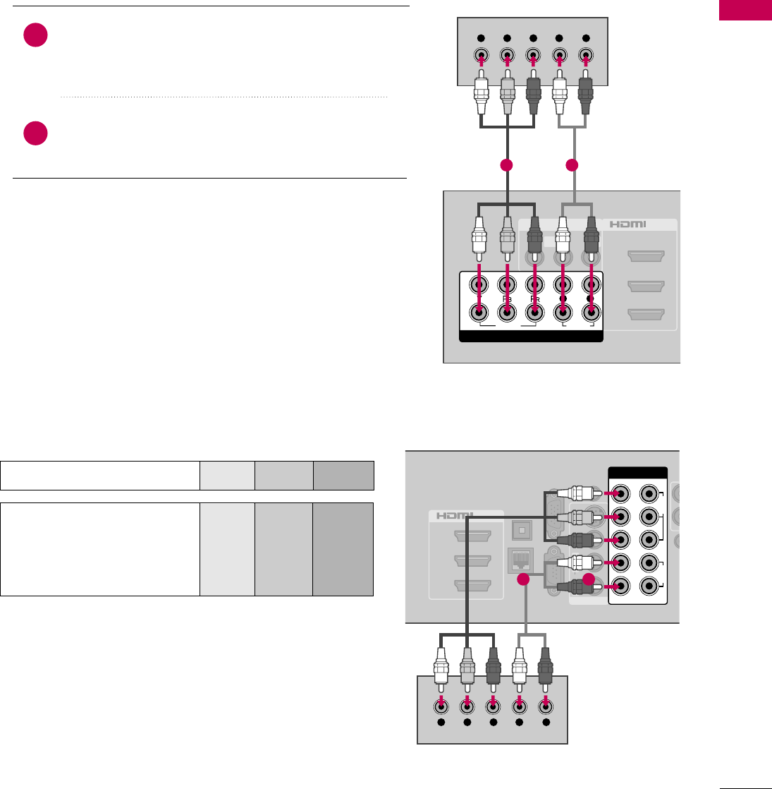
DVD SETUP
Component Connection
Component Input ports
To get better picture quality, connect a DVD player to the
component input ports as shown below.
Component ports on the TV
YPBPR
Video output ports
on DVD player
Y
Y
Y
Y
PB
B-Y
Cb
Pb
PR
R-Y
Cr
Pr
Connect the video outputs (Y, PB, PR)of the DVD to the
COMPONENT IN VIDEO 1 jacks on the TV.
Match the jack colors (Y = green, PB= blue, and PR= red).
Connect the audio outputs of the DVD to the
COMPONENT IN AUDIO 1 jacks on the TV.
1. How to connect
2. How to use
■Turn on the DVD player, insert a DVD.
■Select the Component1 input source on the TV using
the INPUT button on the remote control.
■If connected to COMPONENT IN 2 input, select the
Component2 input source on the TV.
■Refer to the DVD player's manual for operating instructions.
2
1
2
1
3
/DVI IN
OPTICAL
DIGITAL
AUDIO OUT
RGB IN (PC)
LAN
SERVICE
ONLY
AUDIO IN
(RGB/DVI)
RE
CONT
AUDIOVIDEOS-VIDEO
MONO
( )
L R
AV IN 1
COMPONENT IN
VIDEO
AUDIO
12
LYPBPRR
Y L RPBPR
1 2
A
(
AV IN 1
2
3
1
MONO
( )
AUDIOVIDEO L R
/DVI IN
VIDEO
AUDIO
L R
COMPONENT IN
2
1
Y L RPBPR
LCD TV
Plasma TV
1 2
EXTERNAL EQUIPMENT SETUP
30
EXTERNAL EQUIPMENT SETUP
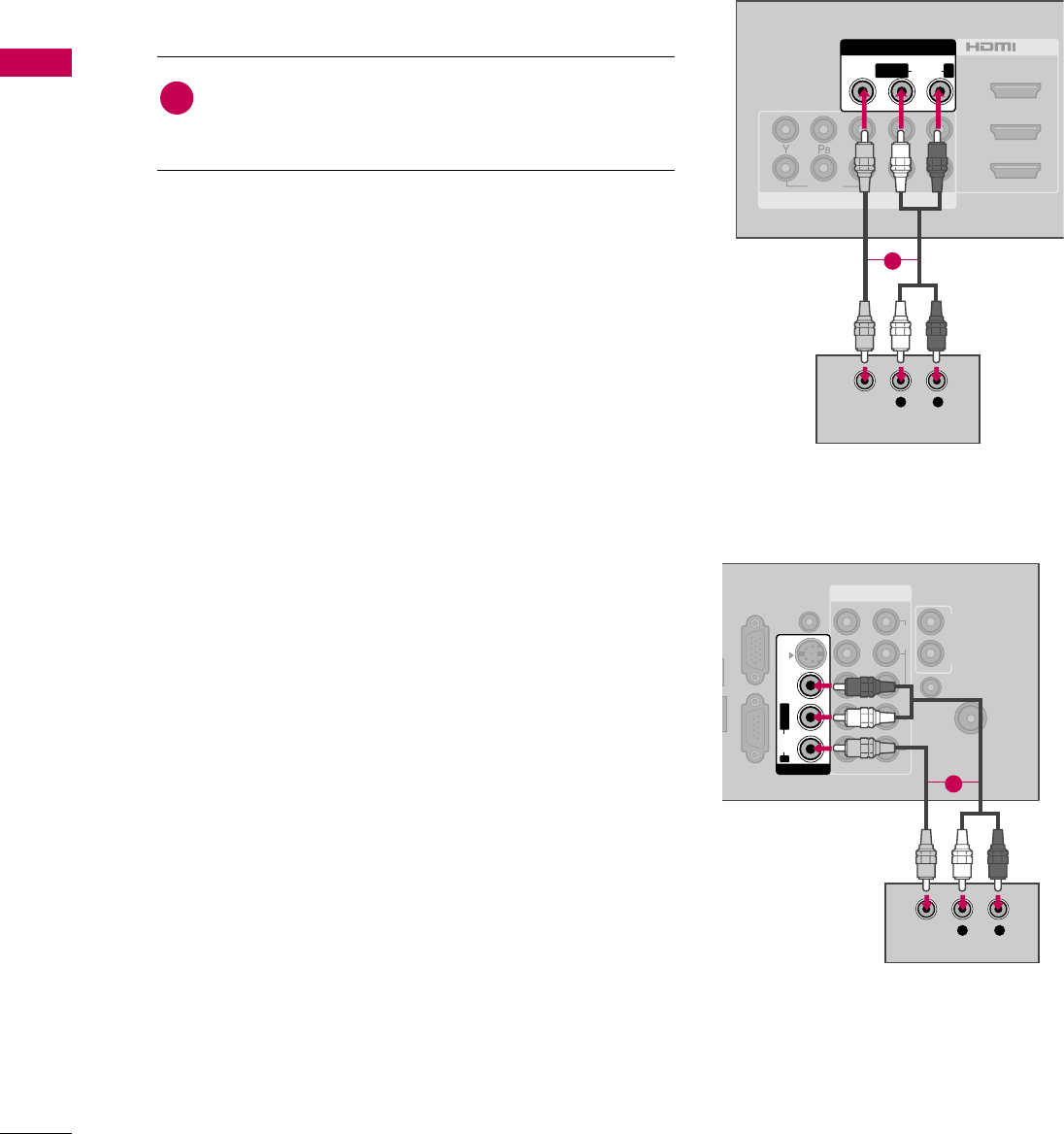
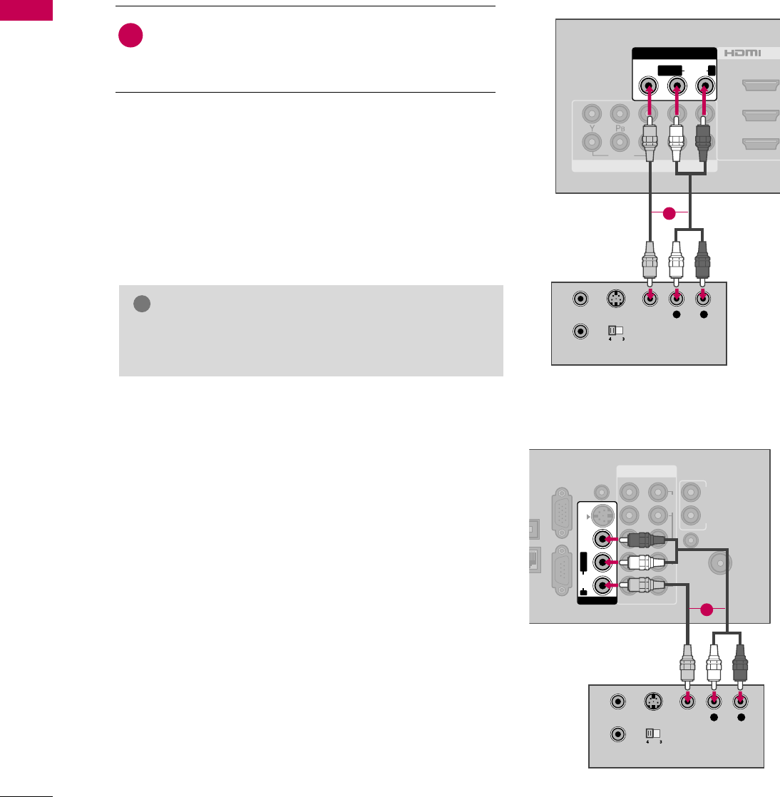
Composite (RCA) Connection
VIDEO
AUDIO
L R
A
(
COMPONENT IN
2
3
1
2
1
/DVI IN
AV IN 1
MONO
( )
AUDIOVIDEO LR
L R
VIDEO
AUDIO
Connect the AUDIO/VIDEO jacks between TV and
DVD. Match the jack colors (Video = yellow, Audio Left
= white, and Audio Right = red)
1. How to connect
2. How to use
■Turn on the DVD player, insert a DVD.
■Select the AV1 or AV2 input source on the TV using the
INPUT button on the remote control.
■Refer to the DVD player's manual for operating instructions.
1
1
COMPONENT IN
ANTENNA/
CABLE IN
L
UT
RGB IN (PC)
SERVICE
ONLY
AUDIO IN
(RGB/DVI)
AUDIO OUT
REMOTE
CONTROL IN
VIDEO
AUDIO
12
LYPBPRR
AUDIOVIDEOS-VIDEO
MONO
( )
L R
AV IN 1
L R
VIDEO
AUDIO
1
LCD TV
Plasma TV
EXTERNAL EQUIPMENT SETUP
31
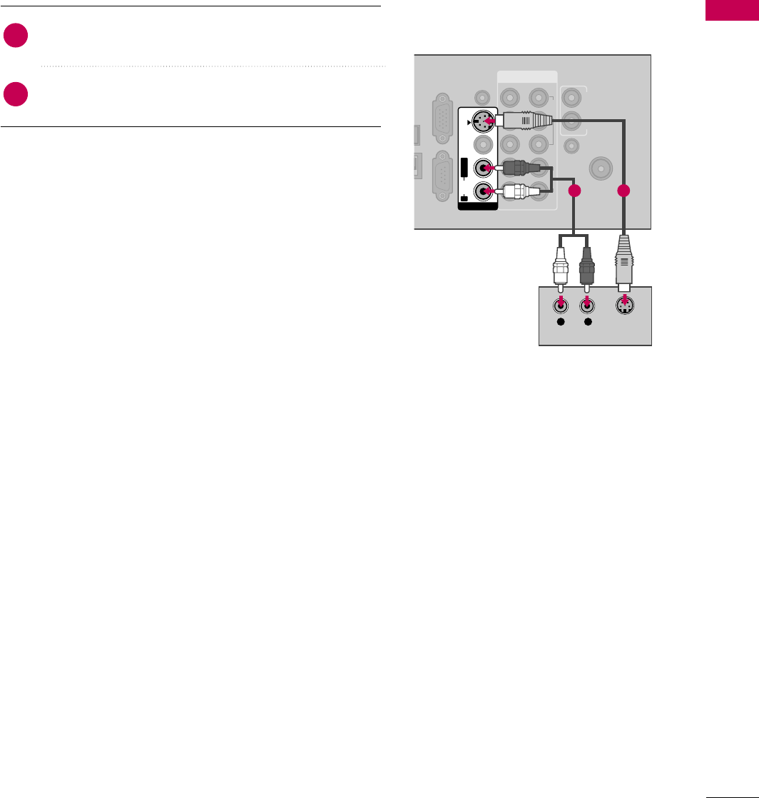
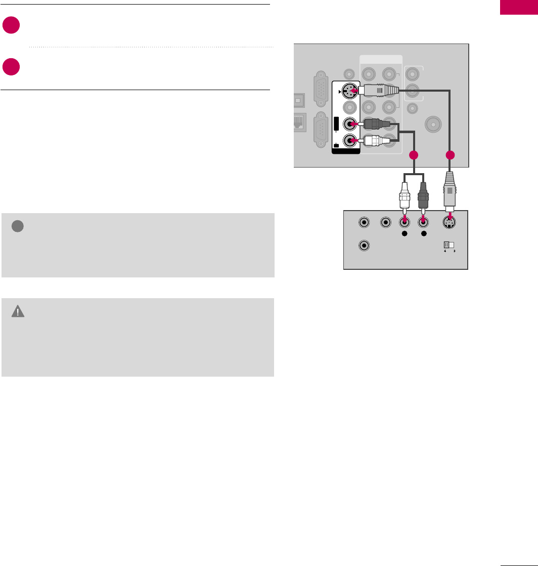
S-Video Connection
(For Plasma TV)
Connect the S-VIDEO output of the DVD to the
S-VIDEO input on the TV.
Connect the audio outputs of the DVD to the AUDIO
input jacks on the TV.
1. How to connect
2. How to use
■Turn on the DVD player, insert a DVD.
■Select the AV1 input source on the TV using the INPUT
button on the remote control.
■Refer to the DVD player's manual for operating instructions.
2
1
COMPONENT IN
ANTENNA/
CABLE IN
AL
AL
OUT
RGB IN (PC)
N
SERVICE
ONLY
AUDIO IN
(RGB/DVI)
AUDIO OUT
REMOTE
CONTROL IN
VIDEO
AUDIO
12
LYPBPRR
AUDIOVIDEOS-VIDEO
MONO
( )
L R
AV IN 1
L R
AUDIO S-VIDEO
1 2
EXTERNAL EQUIPMENT SETUP
32
EXTERNAL EQUIPMENT SETUP
HDMI Connection
O
AUDIO
L R
RS-232C IN
(
CONTROL&SERVICE)
AUDIO IN
(RGB/DVI)
OPTIC
AUD
ANT
CAB
RGB IN (PC)
AV IN 1
MPONENT IN
1
MONO
( )
AUDIOVIDEO L R
2
3
1
/DVI IN
HDMI OUTPUT
1
COM
OPTICAL
DIGITAL
AUDIO OUT
RGB IN (PC)
LAN
SERVICE
ONLY
AUDIO IN
(RGB/DVI)
1
AUDIOVIDEOS-VIDEO
MONO
( )
L R
AV IN 1
2
1
3
/DVI IN
HDMI OUTPUT
Connect the HDMI output of the DVD to the
HDMI/DVI IN 1, 2, 3 or 4jack on the TV.
No separate audio connection is necessary.
HDMI supports both audio and video.
1. How to connect
2. How to use
■Select the HDMI1, HDMI2, HDMI3, or HDMI4 input
source on the TV using the INPUT button on the remote
control.
■Refer to the DVD player's manual for operating instructions.
2
1
GCheck HDMI cable over version 1.3.
If the HDMI cables don’t support HDMI version 1.3, it can
cause flickers or no screen display. In this case use the lat-
est cables that support HDMI version 1.3.
NOTE
!
LCD TV
Plasma TV
1
EXTERNAL EQUIPMENT SETUP
33
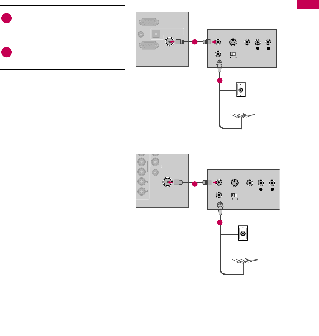
VCR SETUP
Antenna Connection
Connect the RF antenna out socket of the
VCR to the ANTENNA/CABLE IN sock-
et on the TV.
Connect the antenna cable to the RF
antenna in socket of the VCR.
1. How to connect
2. How to use
■Set VCR output switch to 3 or 4 and then
tune TV to the same channel number.
■Insert a video tape into the VCR and press
PLAY on the VCR. (Refer to the VCR owner’s
manual.)
2
1
RS-232C IN
(
CONTROL&SERVICE)
UDIO IN
RGB/DVI)
OPTICAL DIGITAL
AUDIO OUT
RGB IN (PC)
ANTENNA/
CABLE IN
L R
S-VIDEO VIDEO
OUTPUT
SWITCH
ANT IN
ANT OUT
AUDIO
Wall Jack
Antenna
1
2
UDIO OUT
REMOTE
CONTROL IN
VIDEO
AUDIO
2
LPP R
ANTENNA/
CABLE IN
L R
S-VIDEO VIDEO
OUTPUT
SWITCH
ANT IN
ANT OUT
AUDIO
Wall Jack
Antenna
1
2
LCD TV
Plasma TV
EXTERNAL EQUIPMENT SETUP
34
EXTERNAL EQUIPMENT SETUP
Composite (RCA) Connection
GIf you have a mono VCR, connect the audio cable from
the VCR to the AUDIO L/MONO jack of the TV.
NOTE
!
VIDEO
AUDIO
L R
COMPONENT IN
2
3
1
2
1
/DVI I
AV IN 1
MONO
( )
AUDIOVIDEO LR
L R
S-VIDEO VIDEO
AUDIO
OUTPUT
SWITCH
ANT IN
ANT OUT
1
COMPONENT IN
ANTENNA/
CABLE IN
CAL
TAL
O OUT
RGB IN (PC)
AN
SERVICE
ONLY
AUDIO IN
(RGB/DVI)
AUDIO OUT
REMOTE
CONTROL IN
VIDEO
AUDIO
12
LYPBPRR
AUDIOVIDEOS-VIDEO
MONO
( )
L R
AV IN 1
L R
S-VIDEO VIDEO
AUDIO
OUTPUT
SWITCH
ANT IN
ANT OUT
1
Connect the AUDIO/VIDEO jacks between TV and
VCR. Match the jack colors (Video = yellow, Audio Left
= white, and Audio Right = red)
1. How to connect
2. How to use
■Insert a video tape into the VCR and press PLAY on the VCR.
(Refer to the VCR owner’s manual.)
■Select the AV1 input source on the TV using the INPUT
button on the remote control.
■If connected to AV IN 2, select AV2 input source on the TV.
1
LCD TV
Plasma TV
EXTERNAL EQUIPMENT SETUP
35
GDo not connect to both Video and S-Video at the same
time. In the event that you connect both Video and the
S-Video cables, only the S-Video will work.
CAUTION
GS-Video provides better quality than composite. Use it
when available.
NOTE
!
S-Video Connection
(For Plasma TV)
Connect the S-VIDEO output of the VCR to the
S-VIDEO input on the TV.
Connect the audio outputs of the VCR to the AUDIO
input jacks on the TV.
1. How to connect
2. How to use
■Insert a video tape into the VCR and press PLAY on the VCR.
(Refer to the VCR owner’s manual.)
■Select the AV1 input source on the TV using the INPUT
button on the remote control.
2
1
L R S-VIDEOVIDEO
AUDIO
OUTPUT
SWITCH
ANT IN
ANT OUT
COMPONENT IN
ANTENNA/
CABLE IN
PTICAL
GITAL
DIO OUT
RGB IN (PC)
LAN
SERVICE
ONLY
AUDIO IN
(RGB/DVI)
AUDIO OUT
REMOTE
CONTROL IN
VIDEO
AUDIO
12
LYPBPRR
AUDIOVIDEOS-VIDEO
MONO
( )
L R
AV IN 1
1 2
EXTERNAL EQUIPMENT SETUP
36
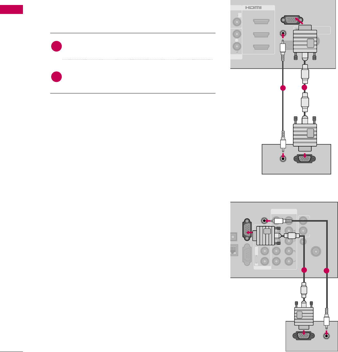
PC SETUP
EXTERNAL EQUIPMENT SETUP
This TV provides Plug and Play capability, meaning that the PC adjusts automatically to the TV's settings.
VGA (D-Sub 15 pin) Connection
DIO
R
RS-232C IN
(
CONTROL&SERVICE)
OPTICAL DIGITAL
AUDIO OUT
ANTENNA/
CABLE IN
1
2
3
1
UDIO R
/DVI IN
AUDIO IN
(RGB/DVI)
RGB IN (PC)
RGB OUTPUT
AUDIO
21
COMPONENT IN
ANTENNA/
CABLE IN
PTICAL
IGITAL
DIO OUT
LAN
SERVICE
ONLY
AUDIO OUT
REMOTE
CONTROL IN
VIDEO
AUDIO
12
LYPBPRR
AUDIOVIDEOS-VIDEO
MONO
( )
L R
AV IN 1
RGB IN (PC)
AUDIO IN
(RGB/DVI)
RGB OUTPUT AUDIO
2
1
Connect the VGA output of the PC to the RGB IN
(P C)jack on the TV.
Connect the PC audio output to the AUDIO IN
(RGB/DVI)jack on the TV.
1. How to connect
2. How to use
■Turn on the PC and the TV.
■Select the RGB-PC input source on the TV using the
INPUT button on the remote control.
2
1
LCD TV
Plasma TV
EXTERNAL EQUIPMENT SETUP
37
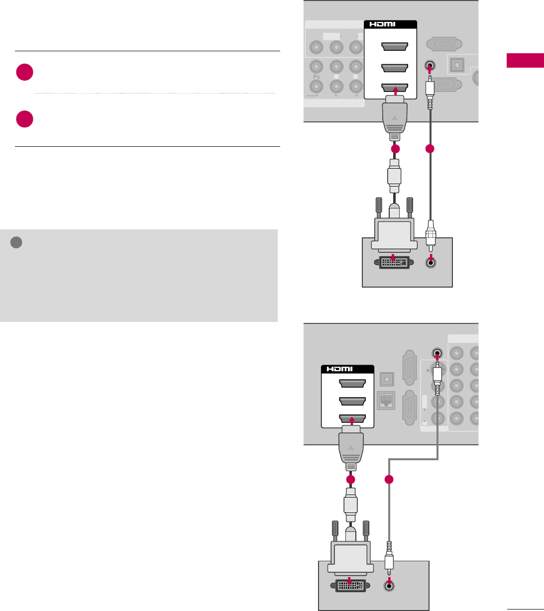
DVI to HDMI Connection
O
AUDIO
L R
RS-232C IN
(
CONTROL&SERVICE)
OPTIC
AU
ANT
CAB
RGB IN (PC)
AV IN 1
MPONENT IN
MONO
( )
AUDIOVIDEO L R
AUDIO IN
(RGB/DVI)
2
3
1
/DVI IN
AUDIO
DVI OUTPUT
12
COMPONENT
OPTICAL
DIGITAL
AUDIO OUT
RGB IN (PC)
LAN
SERVICE
ONLY
12
LYPBPRR
AUDIOVIDEOS-VIDEO
MONO
( )
L R
AV IN 1
2
1
3
/DVI IN
AUDIO IN
(RGB/DVI)
DVI OUTPUT AUDIO
12
Connect the DVI output of the PC to the HDMI/DVI
IN 1, 2, or 3jack on the TV.
Connect the PC audio output to the AUDIO IN
(RGB/DVI) jack on the TV.
1. How to connect
2. How to use
■Turn on the PC and the TV.
■Select the HDMI1, HDMI2, or HDMI3 input source on
the TV using the INPUT button on the remote control.
2
1
GCheck HDMI cable over version 1.3.
If the HDMI cables don’t support HDMI version 1.3, it can
cause flickers or no screen display. In this case use the lat-
est cables that support HDMI version 1.3.
NOTE
!
LCD TV
Plasma TV

EXTERNAL EQUIPMENT SETUP
38
EXTERNAL EQUIPMENT SETUP
NOTES
!
GTo get the the best picture quality, adjust the PC
graphics card to 1920x1080.
GDepending on the graphics card, DOS mode may
not work if a HDMI to DVI Cable is in use.
GIn PC mode, there may be noise associated with
the resolution, vertical pattern, contrast or bright-
ness. If noise is present, change the PC output to
another resolution, change the refresh rate to
another rate or adjust the brightness and contrast
on the PICTURE menu until the picture is clear.
GAvoid keeping a fixed image on the screen for a
long period of time. The fixed image may become
permanently imprinted on the screen.
GThe synchronization input form for Horizontal and
Vertical frequencies is separate.
GDepending on the graphics card, some resolution
settings may not allow the image to be posi-
tioned on the screen properly.
GIf there are overscan in HDMI-PC 1920x1080,
change aspect ratio to Just scan.
GWhen selecting HDMI-PC, set the “Input Label -
PC” in the OPTION menu.
GThe TV provides EDID data to the PC system
with a DDC protocol. DDC protocol is preset for
RGB (Analog RGB), HDMI (Digital RGB) mode.
EXTERNAL EQUIPMENT SETUP
39
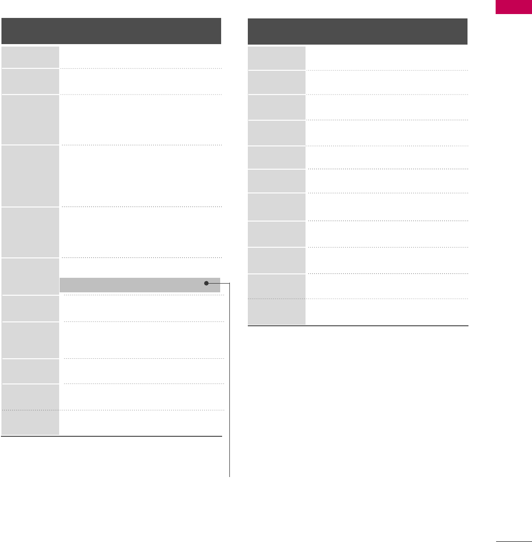
Supported Display Specifications (RGB-PC, HDMI-PC)
* Only RGB-PC mode
Resolution
720x400
640x350
Horizontal Vertical
Frequency(KHz)Frequency(Hz)
31.468 70.09
31.469 70.08
31.469 59.94
37.861 72.80
37.50 75.00
35.156 56.25
37.879 60.31
48.077 72.18
46.875 75.00
48.363 60.00
56.476 70.06
60.023 75.02
47.776 59.87
60.289 74.893
47.712 60.015
63.981 60.02
79.976 75.025
75.00 60.00
66.587 59.934
67.5 60.00
640x480
800x600
1024x768
1280x768
1280x1024
1360x768
1600x1200
1920x1080
RGB-PC
1920x1080
HDMI-PC
LCD TV Plasma TV
Horizontal Vertical
Frequency(KHz)Frequency(Hz)
31.468 70.09
31.469 70.08
31.469 59.94
37.879 60.31
48.363 60.00
47.776 59.87
47.712 60.015
63.981 60.02
75.00 60.00
66.587 59.934
67.5 60.00
Resolution
720x400
1360x768
640x480
800x600
1024x768
640x350
1280x1024
1600x1200
1920x1080
RGB-PC
1920x1080
HDMI-PC
1280x768
EXTERNAL EQUIPMENT SETUP
40
EXTERNAL EQUIPMENT SETUP
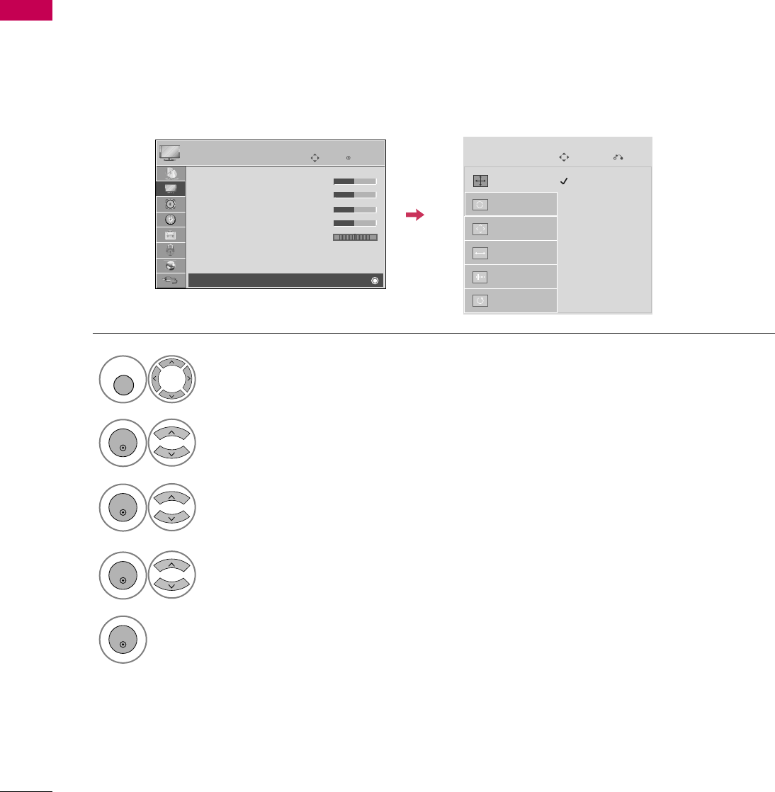
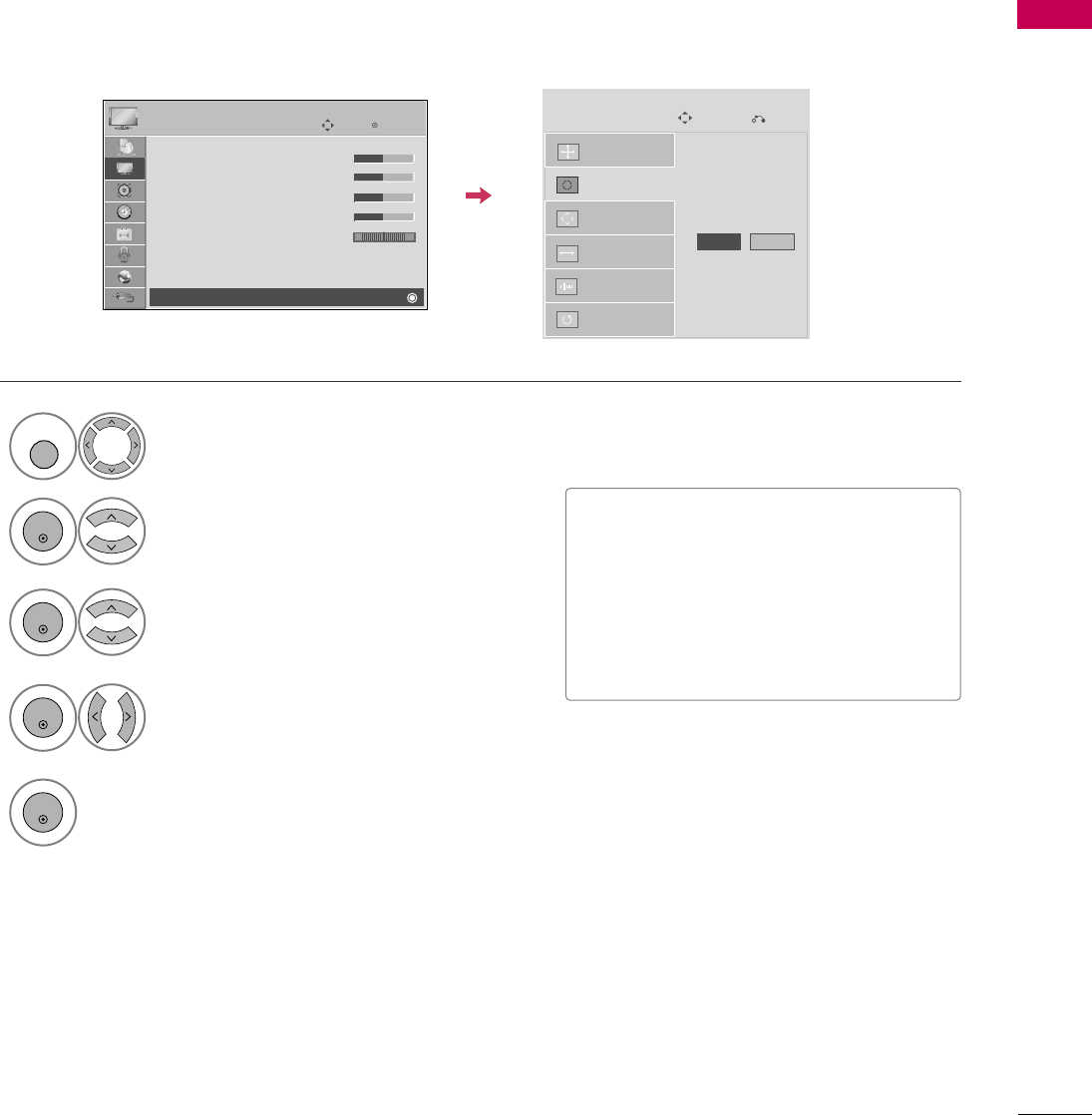
Screen Setup for PC mode
Selecting Resolution
You can choose the resolution in RGB-PC mode.
The Position, Phase, and Size can also be adjusted.
Select PICTURE.
Select Screen (RGB-PC).
Select Resolution.
Select the desired resolution.
1024 x 768
1280 x 768
1360 x 768
Auto Config.
Resolution
Position
Size
Phase
Reset
SCREEN
Move
Prev.
1
MENU
3
4
2
ENTER
ENTER
ENTER
5
ENTER
Enter
Move
PICTURE
E
RG
• Contrast 50
• Brightness 50
• Sharpness 50
• Color 50
• Tint 0
• Advanced Control
• Picture Reset
Screen (RGB-PC)
EXTERNAL EQUIPMENT SETUP
41
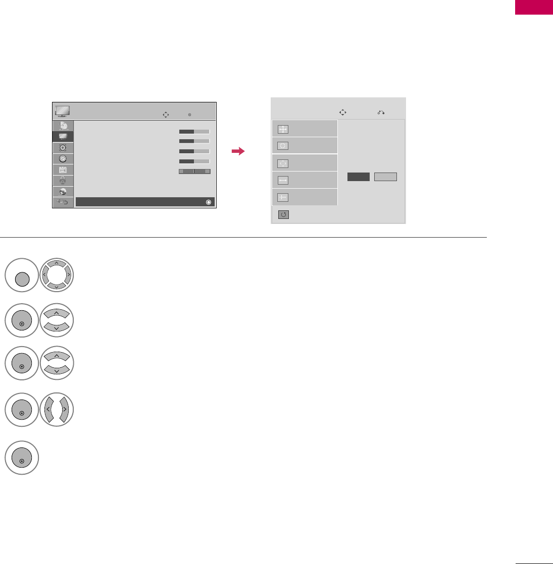
Auto Configure
Automatically adjusts picture position and minimizes image instability. After adjustment, if the image is still
not correct, try using the manual settings or a different resolution or refresh rate on the PC.
Select Screen (RGB-PC).
Select Auto Config..
Auto Config.
Resolution
Position
Size
Phase
Reset
SCREEN
Move
Prev.
To Set
3
2
ENTER
ENTER
Select Yes.
4
ENTER
Start Auto Configuration.
5
ENTER
Select PICTURE.
1
MENU
■If the position of the image is still not
correct, try Auto adjustment again.
■If picture needs to be adjusted again
after Auto adjustment in RGB-PC, you
can adjust the Position, Size or
Phase.
Yes No
Enter
Move
PICTURE
E
RG
• Contrast 50
• Brightness 50
• Sharpness 50
• Color 50
• Tint 0
• Advanced Control
• Picture Reset
Screen (RGB-PC)

EXTERNAL EQUIPMENT SETUP
42
EXTERNAL EQUIPMENT SETUP
Adjustment for screen Position, Size, and Phase
If the picture is not clear after auto adjustment and especially if characters are still trembling, adjust the picture
phase manually.
This feature operates only in RGB-PC mode.
Select Position, Size, or Phase.
Make appropriate adjustments.
Auto Config.
Resolution
Position
Size
Phase
Reset
GF
D
E
SCREEN
Move
Prev.
3
ENTER
4
ENTER
■Position: This function is to adjust pic-
ture to left/right and up/down as you
prefer.
■Size: This function is to minimize any
vertical bars or stripes visible on the
screen background. And the horizontal
screen size will also change.
■Phase: This function allows you to
remove any horizontal noise and clear or
sharpen the image of characters.
Select PICTURE.
Select Screen (RGB-PC).
1
MENU
2
ENTER
5
ENTER
Enter
Move
PICTURE
E
RG
• Contrast 50
• Brightness 50
• Sharpness 50
• Color 50
• Tint 0
• Advanced Control
• Picture Reset
Screen (RGB-PC)
EXTERNAL EQUIPMENT SETUP
43
Screen Reset (Reset to original factory values)
Returns Position, Size, and Phase to the default factory settings.
This feature operates only in RGB-PC mode.
Auto Config.
Position
Resolution
Size
Phase
Reset
SCREEN
Move
Prev.
To Set
Select Reset.
3
ENTER
Select PICTURE.
Select Screen (RGB-PC).
1
MENU
2
ENTER
Select Yes.
4
ENTER
5
ENTER
Yes No
Enter
Move
PICTURE
E
RG
• Contrast 50
• Brightness 50
• Sharpness 50
• Color 50
• Tint 0
• Advanced Control
• Picture Reset
Screen (RGB-PC)
EXTERNAL EQUIPMENT SETUP
44
OTHER A/V SOURCE SETUP
USB CONNECTION
EXTERNAL EQUIPMENT SETUP
AV IN 2
L/MONO
R
AUDIO
VIDEO
USB IN
IN 4
L R
VIDEO
Camcorder
Video Game Set
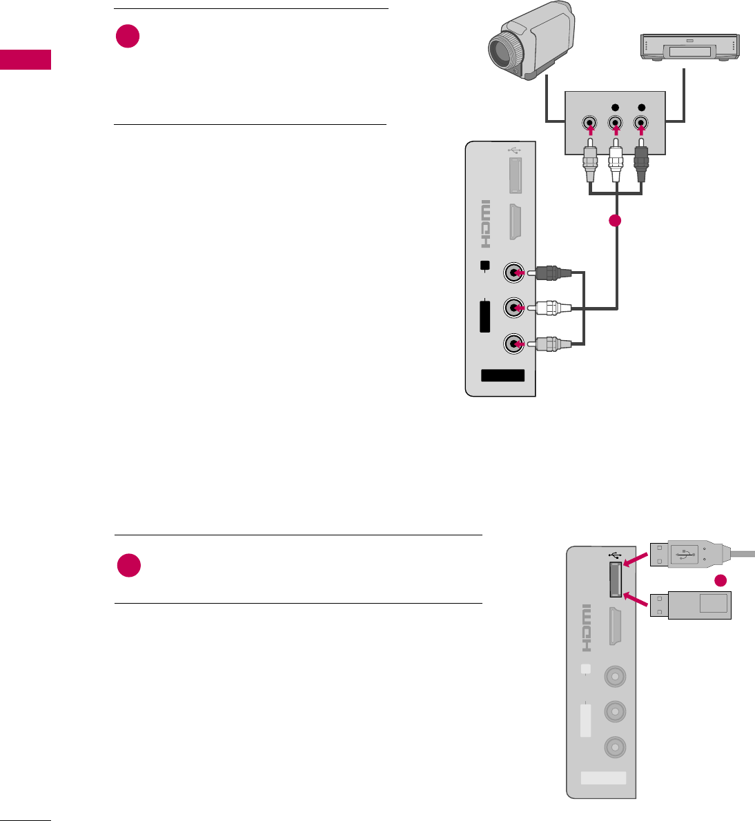
Connect the AUDIO/VIDEO jacks
between TV and external equipment.
Match the jack colors
.
(Video = yellow, Audio Left = white, and
Audio Right = red)
1. How to connect
2. How to use
■Select the AV2 input source on the TV using
the INPUT button on the remote control.
■If connected to AV IN 1 input, select the AV1
input source on the TV.
■Operate the corresponding external equipment.
1
1
USB IN
IN 4
AV IN 2
L/MONO
R
AUDIO
VIDEO
Memory Key
Connect the USB device to the USB I N jack on the side
of TV.
1. How to connect
1
2. How to use
■After connecting the USB IN jack, you use the USB func-
tion. (Gp.60)
1
or
EXTERNAL EQUIPMENT SETUP
45
AUDIO OUT CONNECTION
R
RS-232C IN
(
CONTROL&SERVICE)
AUDIO IN
(RGB/DVI)
ANTENNA/
CABLE IN
RGB IN (PC)
2
3
1
R
/DVI IN
OPTICAL DIGITAL
AUDIO OUT
1
2
COMPONENT IN
ANTENNA/
CABLE IN
CAL
TAL
OUT
RGB IN (PC)
N
SERVICE
ONLY
AUDIO IN
(RGB/DVI)
AUDIO OUT
REMOTE
CONTROL IN
VIDEO
AUDIO
12
LYPBPRR
AUDIOVIDEOS-VIDEO
MONO
( )
L R
AV IN 1
AUDIO OUT
L R
AUDIO
1
GWhen connecting with external audio equipment, such as
amplifiers or speakers, you can turn the TV speakers off in
the menu. (G p.?)
NOTE
!
GDo not look into the optical output port. Looking at the
laser beam may damage your vision.
GAudio with ACP (Audio Copy Protection) function may
block digital audio output.
CAUTION
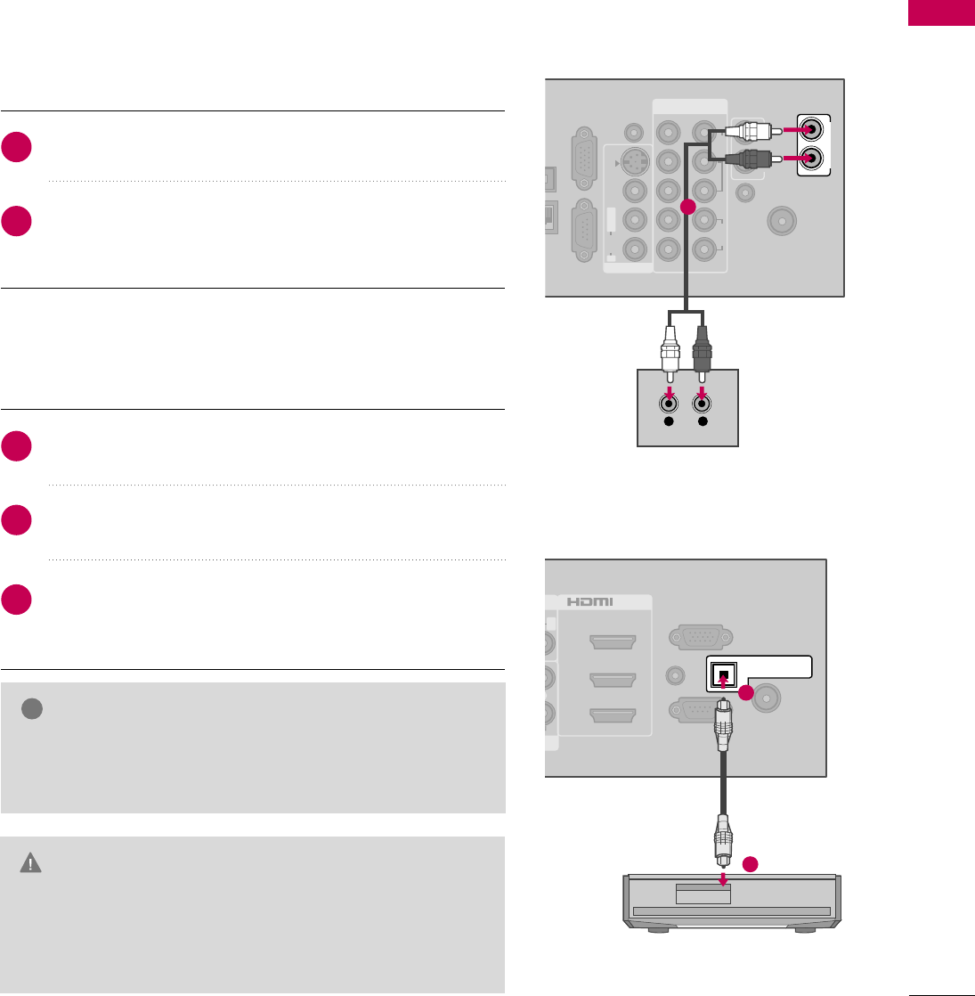
Connect one end of the optical cable to the TV port of
OPTICAL DIGITAL AUDIO OUT.
Connect the other end of the optical cable to the digital
audio input on the audio equipment.
Set the “TV Speaker option - Off” in the AUDIO menu.
(Gp.87). See the external audio equipment instruction
manual for operation.
1. How to connect
2
3
1
Send the TV’s audio to external audio equipment via the Audio Output port.
If you want to enjoy digital broadcasting through 5.1-channel speakers, connect the OPTICAL DIGITAL
AUDIO OUT terminal on the back of TV to a Home Theater (or amp).
LCD TV
Plasma TV
Digital
Connect audio outputs to the TV’s AUDIO OUT jacks.
Set the “TV Speaker option - Off” in the AUDIO menu. (G
p.93). See the external audio equipment instruction manu-
al for operation.
1. How to connect
2
1
Analog
(For Plasma TV)
EXTERNAL EQUIPMENT SETUP
46
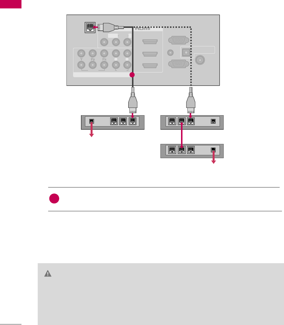
NETWORK SETUP
EXTERNAL EQUIPMENT SETUP
CAUTION
This TV can be connected to a local area network (LAN) via the LAN port. After making the physical connec-
tion, the TV needs to be set up for network communication.
VIDEO
AUDIO
L R
RS-232C IN
(
CONTROL&SERVICE)
AUDIO IN
(RGB/DVI)
OPTICAL DIGITAL
AUDIO OUT
ANTENNA/
CABLE IN
RGB IN (PC)
AV IN 1
COMPONENT IN
2
3
1
2
1
MONO
( )
AUDIOVIDEO L R
/DVI IN
LAN
1
Connect the Modem or Router LAN port to the LAN port on the TV.
Broadband modem
Broadband modem
Router
Broadband Service
1. How to connect
1
2. How to use
■After connecting the LAN port, you use the NETWORK function. (Gp.?)
■Please contact the specifications of your telecommunication carrier or internet service
provider for detail information.
GWhen plugging or unplugging the LAN cable, hold the plug portion of the cable. When
unplugging, do not pull on the LAN cable but unplug while pressing down on the lock.
GDo not connect a modular phone cable to the LAN port.
GSince there are various connection method, please follow the specifications of your telecom-
munication carrier or internet service provider.
i.e) LCD TV
Broadband Service

EXTERNAL EQUIPMENT SETUP
47
GUse a commercially available straight LAN cable
(Category 5/CAT5 or better with RJ45 connec-
tor).???
GBy connecting the TV to broadband Internet, you
can use Photo and Music list. (G p.87)
GDepending on the internet service provider (ISP),
the number of devices that can receive internet
service may be limited by the applicable terms of
service. For details, contact your ISP.
GLG is not responsible for any malfunction of the
player and/or the internet connection feature due
to communication errors/malfunctions associated
with your broadband internet connection, or other
connected equipment.
GLG is not responsible for any trouble in your inter-
net connection.
GThe features of JPG and MP2 file made available
through the internet connection are not created or
provided by LG, and LG is not responsible for their
functionality or continued availability. Some file
related material available by the internet connec-
tion may not be compatible with the TV. If you
have questions about such content, please contact
the producer of the disc.
GSome internet contents may require a higher band-
width connection.
GEven if the TV is properly connected and config-
ured, some internet contents may not operate
properly because of internet congestion, the qual-
ity or bandwidth of your internet service, or prob-
lems at the provider of the content.
GSome internet connection operations may not be
possible due to certain restrictions set by the
Internet service provider (ISP) supplying your
broadband Internet connection.
GAny fees charged by an ISP including, without lim-
itation, connection charges are your responsibility.
GA 10 Base-T or 100 Base-TX LAN port is required
for connection to this TV. If your internet service
does not allow for such a connection, you will not
be able to connect the TV.
GYou must use a Router to use xDSL service.
GA DSL modem is required to use DSL service and a
cable modem is required to use cable modem service.
Depending on the access method of and subscriber
agreement with your ISP, you may not be able to
use the internet connection feature contained in
this player or you may be limited to the number of
devices you can connect at the same time. (If your
ISP limits sub-scription to one device, this player
may not be allowed to connect when a PC is
already connected.)
GThe use of a “Router” may not be allowed or its
usage may be limited depending on the policies
and restrictions of your ISP. For details, contact
your ISP directly.
GYour ISP may protect this player from being con-
nected to network when confirming MAC
ADDRESS. In that case, contact your ISP to request
to initialize MAC ADDRESS.
NOTE
!
WATCHING TV / CHANNEL CONTROL
48
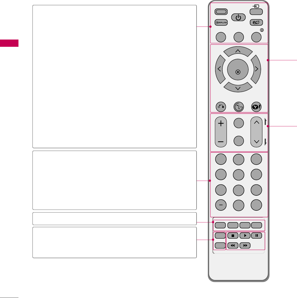
REMOTE CONTROL FUNCTIONS
WATCHING TV / CHANNEL CONTROL
When using the remote control, aim it at the remote control sensor on the TV.
FAV
MARK
AV MODE
POWER
Q. MENU MENU
WIDGETS
RETURN
NETCAST
VOL CH
123
456
78
0
9
FLASHBK
P
A
G
E
INPUT
ENERGY SAVING
LIST
ENTER
INFO
CHAR/NUM
DELETE
MUTE
ABC DEF
GHI
WXYZ
TUV
PQRS
MNO
JKL
RATIO
FREEZE
AV MODE
SIMPLINK
POWER
INPUT
ENERGY SAVING
Q.MENU
MENU
INFO
— (DASH)
LIST
FLASHBK
COLOR KEYS
RATIO
FREEZE
(For Plasma TV)
Toggles through preset Video and Audio modes. G p.64
See a list of AV devices connected to TV.
When you toggle this button, the SIMPLINK menu
appears at the screen. G p.66-67
Turns the TV on from standby or off to standby.
Rotates through inputs.
Also switches the TV on from standby. G p.62
Adjusts the Energy Saving. Gp.?
Opens the list of Quick Menu options. Gp.54
Displays the main menu or clears all on-screen displays
and return to TV viewing.
Displays channel information at the top of the screen.
Gp.60
Used to enter a program number for multiple program
channels such as 2-1, 2-2, etc.
Displays the channel table. Gp.58
Tunes to the last channel viewed.
Uses for Yahoo! Widets or Optional functions.
Changes the aspect ratio. Gp.?
Freezes the current frame.
NUMBER button
WATCHING TV / CHANNEL CONTROL
49
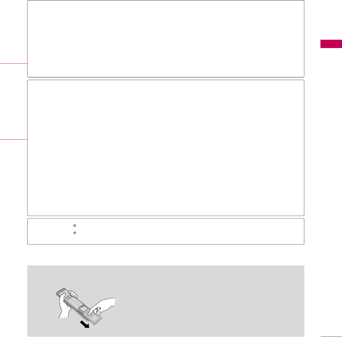
■
Open the battery compartment cover on the back side and
install the batteries matching correct polarity.
■
Install two 1.5V AAA batteries. Don’t mix old or used bat-
teries with new ones.
■
Close cover.
Installing Batteries
THUMBSTICK
(Up/Down/Left
Right/ENTER)
RETURN
NETCAST
WIDGETS
VOLUME UP
/DOWN
FAV
MARK
CHAR/NUM
MUTE
DELETE
CHANNEL
UP/DOWN
PAGE
UP/DOWN
Navigates the on-screen menus and adjusts the system settings to your preference.
Allows the user to move return one step in an interactive application or other user interaction
function.
Select the desired NETCAST menu source. (Yahoo widgets, Netflix, My media) Gp.?
WIDGETS for activating and deactivating the platform and widget user interface. Gp.?
Adjusts the volume.
Scroll through the programmed Favorite channels. Gp.59
Select the input to apply the Picture Wizard settings. Gp.?
Use to mark or unmark a photo/music. Gp.?
Shifts the Character or Number
Switches the sound on or off. Gp.50
? G
Changes the channel.
Moves from one full set of screen information to the next one.
Controls USB menu (Photo List and Music List.)
Controls the SIMPLINK compatible devices.
USB,
SIMPLINK
Control buttons
WATCHING TV / CHANNEL CONTROL
50
TURNING ON THE TV
WATCHING TV / CHANNEL CONTROL
NOTE
!
First, connect power cord correctly.
And switch the AC power control switch on TV (For LCD TV).
At this moment, the TV switches to standby mode.
■In standby mode to turn TV on, press the , INPUT,CH (DE or ) button on the TV or press the
POWER, INPUT, CH ( or ), Number (0~9) button on the remote control.
Select the viewing source by using the INPUT button on the remote control.
■This TV is programmed to remember which power state it was last set to, even if the power cord is out.
When finished using the TV, press the POWER button on the remote control. The TV reverts to standby
mode.
1
2
3
Press the CH ( or )or NUMBER buttons to select a channel number.
1
VOLUME ADJUSTMENT
CHANNEL SELECTION
Press the VOL (+ or -) button to adjust the volume.
If you want to switch the sound off, press the MUTE button.
You can cancel the Mute function by pressing the MUTE or VOL (+ or -)
button.
Adjust the volume to suit your personal preference.
1
2
3
GIf you intend to be away on vacation, disconnect the power plug from the wall power outlet.
GIf you do not complete the Initial setting, it will appear whenever the TV is switched on until the Initial
setting procedure is completed.
GIf the TV is unplugged once or turn off with the AC power control switch or button on the TV, reset the
Clock function.
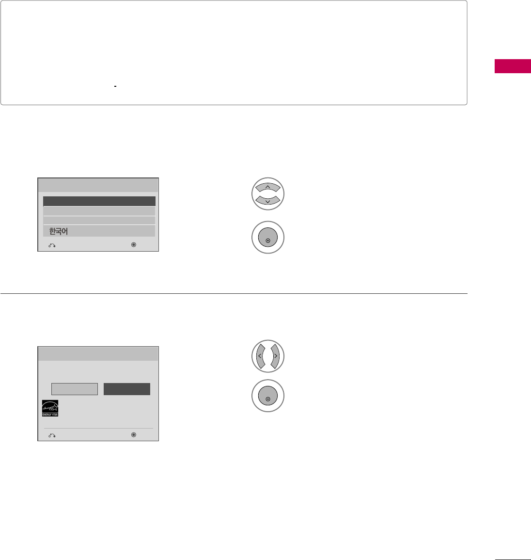
WATCHING TV / CHANNEL CONTROL
51
INITIAL SETTING
This Function guides the user to easily set the essential items for viewing the TV for the first time when pur-
chasing the TV. It will be displayed on the screen when turning the TV on for the first time. It can also be acti-
vated from the user menus.
■Default selection is “Home Use”. We recommend setting the TV to “Home Use” mode for the best pic-
ture in your home environment.
■“Store Demo” Mode is only intended for use in retail environments. Customers can adjust the “Picture
menu - Picture mode” manually while inspecting the TV, but the TV will automatically return to preset in-
store mode after 5 minutes.
■“Store Demo” Mode is an optimal setting for displaying at stores. “Store Demo” mode initializes the TV
to set the image quality.
Language
English
Español
Français
Selecting the environment.
Choose the setting mode you want.
Select [Home Use] to use this TV at home.
To use this TV at Store, select [Store Demo].
Store Demo
Home Use
Mode Setting
NextPrevious
NextPrevious
Select Menu Language.
1
2
ENTER
Select Home Use.
1
3
ENTER
Step1. Selecting Language
Step2. Mode setting
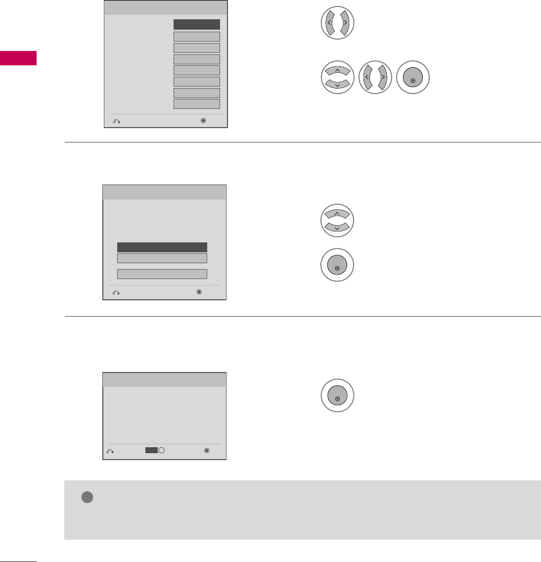
WATCHING TV / CHANNEL CONTROL
52
WATCHING TV / CHANNEL CONTROL
Select Auto or Manual.
1
Select the network settings. With the
settings, you can use LG NetCast
services such as Yahoo! Widgets,
Netflix, and YouTube.
Networking Setting
Step3. Time setting
Step4. Network Setting
Check your antenna connection and start
Auto Tuning.
1
ENTER
Before starting,
be sure that the
TV antenna is connected.
Auto Tuning
Step5. Auto Tuning
■You can also adjust Initial Setting in the OPTION menu.
NOTE
!
Select desired time
option.
2
ENTER
Month
Current Time Setting
02
Date 21
Year 2009
Hour 10 AM
Minute 10
Time Zone Eastern
Daylight Saving
Auto
F Auto G
Time Setting
NextPrevious
Next
Simple Manual
Previous
INFO
i
SetPrevious
IP Auto Resetting
IP Manual Resetting
Skip
Select IP Auto Resetting.
1
2
ENTER
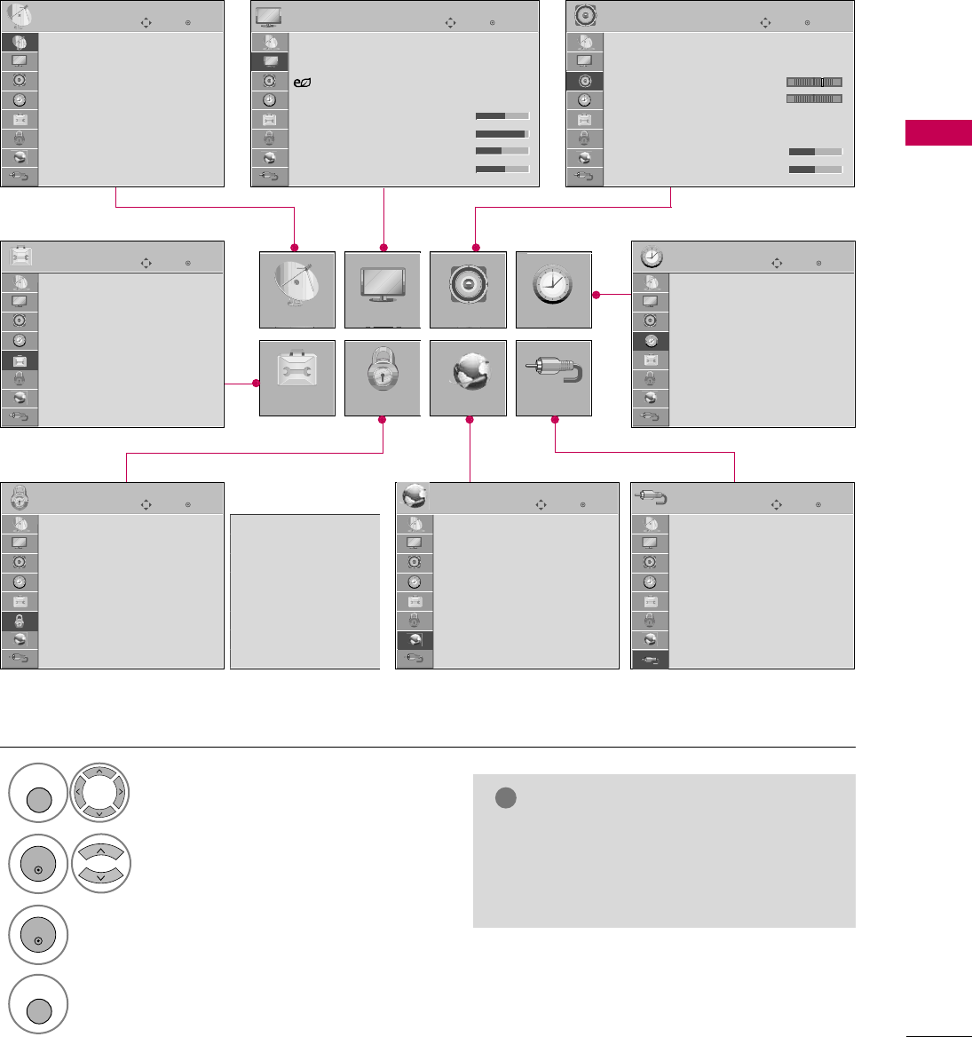
WATCHING TV / CHANNEL CONTROL
53
ON-SCREEN MENUS SELECTION
Your TV's OSD (On Screen Display) may differ slightly from that shown in this manual.
Display each menu.
Select a menu item.
Accept the current selection.
1
MENU
3
2
ENTER
ENTER
Return to TV viewing.
4
MENU
Enter
Move
Auto Tuning
Manual Tuning
Channel Edit
CHANNEL
CHANNEL
OPTION
PICTURE
LOCK
AUDIO
NETWORK
TIME
INPUT
Enter
Move
Aspect Ratio : 16:9
Picture Wizard
Energy Saving
: Off
Picture Mode : Standard
• Backlight 70
• Contrast 90
• Brightness 50
• Sharpness 70
PICTURE
E
Enter
Move
Auto Volume : On
Clear Voice II : On
• Level 3
Balance 0
Sound Mode : Standard
•
SRS TruSurround XT:
Off
• Treble 50
• Bass 50
AUDIO
E
Enter
Move
Clock
Off Time : Off
On Time : Off
Sleep Timer : Off
TIME
Enter
Move
Network Setting
Software Update
ESN
NETWORK
E
Enter
Move
TV
AV1
AV2
Component1
Component2
RGB-PC
HDMI1
HDMI2
INPUT
E
Enter
Move
Lock System : Off
Set Password
Block Channel
Movie Rating
TV Rating-Children
TV Rating-General
Downloadable Rating
Input Block
LOCK
Lock System : Off
Set Password
Block Channel
TV Rating-English
TV Rating-French
Downloadable Rating
Input Block
Enter
Move
Menu Language : English
Audio Language : English
Input Label
THX Media Director : Off
SIMPLINK : On
Key Lock : Off
Simple Manual
Caption : Off
OPTION
For USA For Canada
E
LR
-+
NOTE
!
GISM Method, THX Media Director:
Only Plasma TV.
GBacklight, Power Indicator: Only
LCD TV.
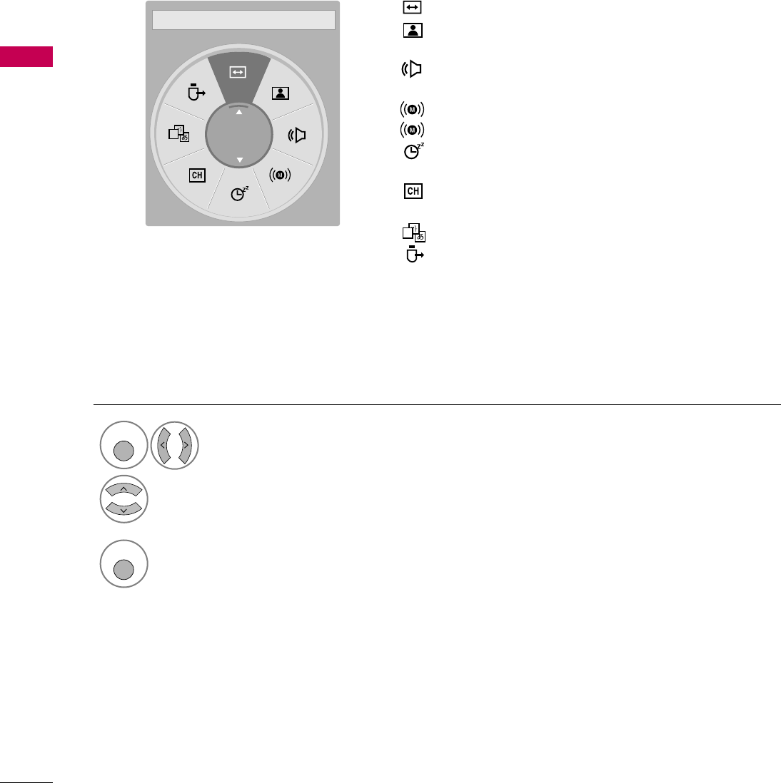
WATCHING TV / CHANNEL CONTROL
54
QUICK MENU
WATCHING TV / CHANNEL CONTROL
Display each menu.
Make appropriate adjustments.
Your TV's OSD (On Screen Display) may differ slightly from what is shown in this manual.
Q.Menu (Quick Menu) is a menu of features which users might use frequently.
1
Q. MENU
2
3
Q. MENU
Return to TV viewing.
A
16:9
F Aspect Ratio GAspect Ratio: Selects your desired picture format.
Picture Mode: Selects the factory preset picture
depend on the viewing environment.
Sound Mode: Selects the factory preset sound for type
of program.
Multi Audio: Changes the audio language (Digital signal).
SAP: Selects MTS sound (Analog signal).
Sleep Timer: Select the amount of time before your TV
turns off automatically.
Del/Add/Fav: Select channel you want to add/delete or
add the channel to the Favorite List.
Caption: Select on or off.
USB Device: Select “Eject” in order to eject a USB
device.
A
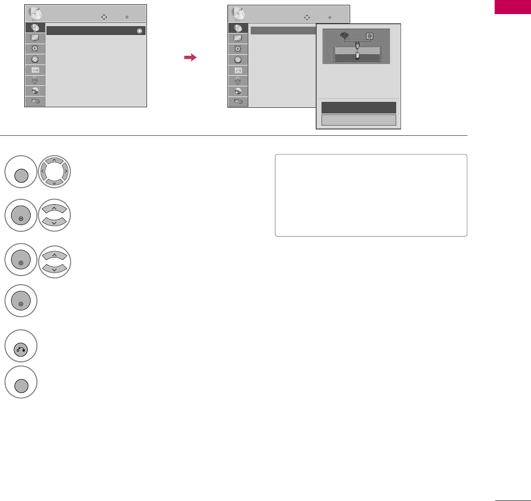
WATCHING TV / CHANNEL CONTROL
55
CHANNEL SETUP
Auto Scan (Auto Tuning)
Automatically finds all channels available through antenna or cable inputs, and stores them in memory on the
channel list.
Select CHANNEL.
Select Auto Tuning.
Select Yes.
Run Auto tuning.
Enter
Move
CHANNEL
Enter
Move
CHANNEL
1
MENU
3
2
ENTER
ENTER
4
ENTER
Auto Tuning
Manual Tuning
Channel Edit
Auto Tuning
Manual Tuning
Channel Edit
■The TV will ask for a password if parental
control has been activated (LOCK
Menu). Use the password you set up in
the LOCK Menu to allow a channel
search.
5
RETURN
Return to the previous menu.
MENU
Return to TV viewing.
Check your antenna connection.
The previous channel information
will be updated during Auto
Tuning.
Yes
No
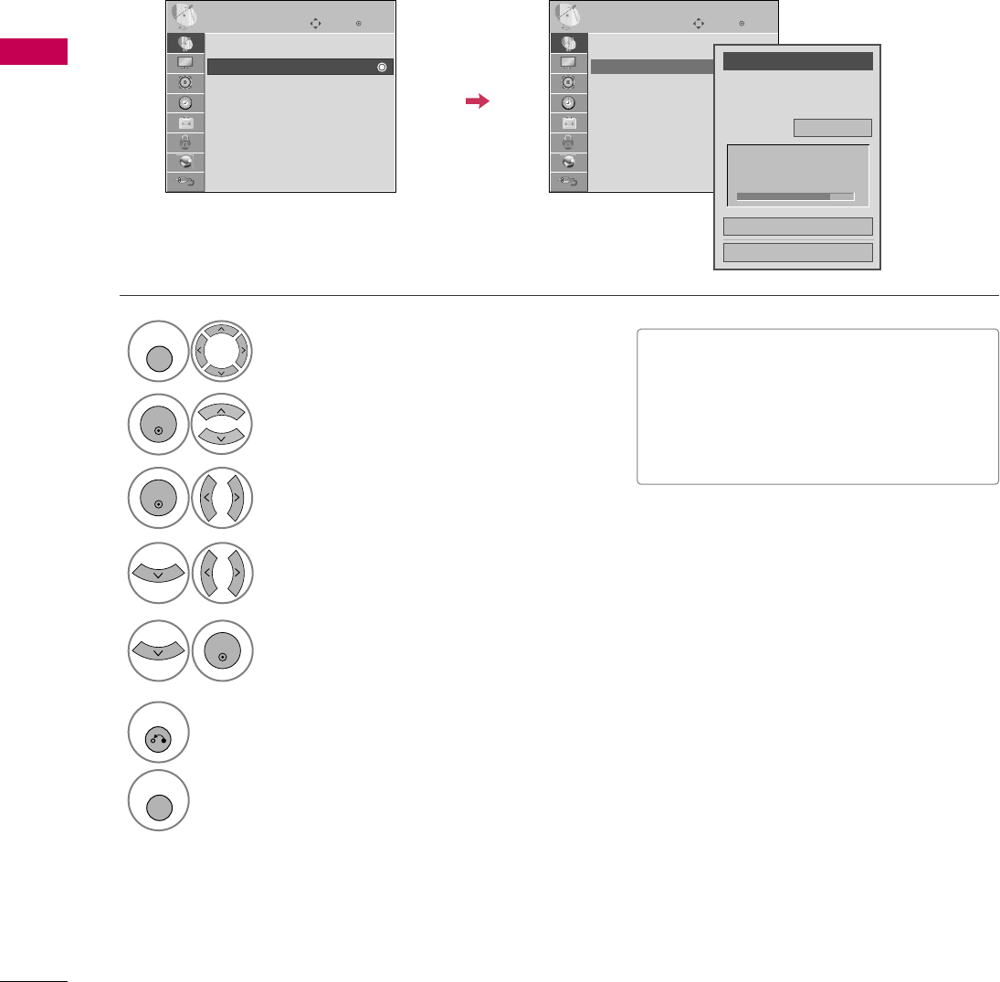
WATCHING TV / CHANNEL CONTROL
56
WATCHING TV / CHANNEL CONTROL
Select CHANNEL.
1
MENU
2
ENTER
When selecting DTV or CADTV input signal, you can view the on-screen signal strength monitor to see the qual-
ity of the signal being received.
Add/Delete Channel (Manual Tuning)
Enter
Move
CHANNEL
Enter
Move
CHANNEL
Channel
Select channel type and
RF-channel number.
F
DTV
G
2
Close
Delete
Auto Tuning
Manual Tuning
Channel Edit
DTV 2-1
Bad Normal Good
Select Manual Tuning.
Select DTV, T V, CADTV, or CATV.
Select channel you want to add
or delete.
3
ENTER
4
Select Add or Delete.
5
ENTER
Auto Tuning
Manual Tuning
Channel Edit
■The TV will ask for a password if parental
control has been activated (LOCK
Menu). Use the password you set up in
the LOCK Menu to allow a channel
search.
6
RETURN
Return to the previous menu.
MENU
Return to TV viewing.
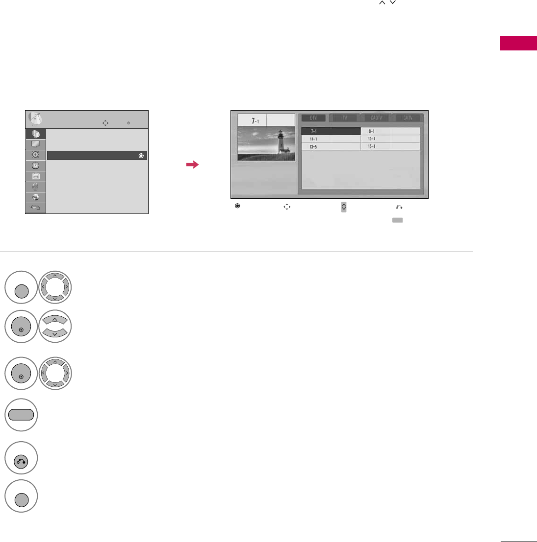
WATCHING TV / CHANNEL CONTROL
57
Select a channel.
Add or delete a channel.
3
ENTER
4
The channels in the Channel Edit List are displayed in black and the channels deleted from the Channel Edit
List are displayed in blue.
When a channel number is deleted, it means that you will be unable to select it using CH button during TV
viewing.
If you wish to select the deleted channel, directly enter the channel number with the NUMBER buttons or select
it in the Channel Edit menu.
Channel Editing
Enter
Move
CHANNEL
Auto Tuning
Manual Tuning
Channel Edit
Select CHANNEL.
1
MENU
2
ENTER
Select Channel Edit.
Return to the previous menu.
5
RETURN
Return to TV viewing.
MENU
Ch. Change Page Change
CH
Navigation Previous
Add/Delete
BLUE
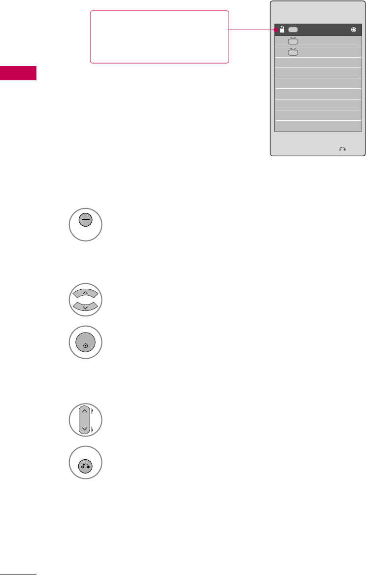
WATCHING TV / CHANNEL CONTROL
58
CHANNEL LIST
WATCHING TV / CHANNEL CONTROL
Exit
2-1
3-1
4-1
DTV
DTV
DTV
Channel List
You can check which channels are stored in the memory by displaying the channel list.
Display the Channel List.
1
LIST
Displaying Channel List
Select a channel.
1
Switch to the chosen channel number.
2
ENTER
Selecting a channel in the channel list
Turn the pages.
1
CH
P
A
G
E
Return to TV viewing.
2
RETURN
Paging through a channel list
This padlock is displayed
when the channel is locked
with parental control.
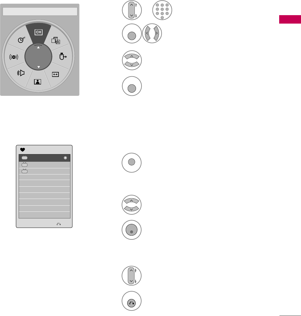
WATCHING TV / CHANNEL CONTROL
59
FAVORITE CHANNEL SETUP
FAVORITE CHANNEL LIST
Favorite Channels are a convenient feature that lets you quickly select channels of your choice without waiting
for the TV to select all the in-between channels.
To tune to a favorite channel, press the FAV (Favorite) button repeatedly.
Return to TV viewing.
4
Q. MENU
Select Favorite.
3
Select your desired channel.
1
CH
P
A
G
E
123
456
78
0
9
ABC DEF
GHI
WXYZ
TUV
PQRS
MNO
JKL
2
Q. MENU
Select Del/Add/Fav.
or
A
Favorite
F Del/Add/Fav G
Exit
2-1
3-1
4-1
DTV
DTV
DTV
Favorite List
Select a channel.
1
Switch to the chosen channel number.
2
ENTER
Selecting a channel in the favorite channel list
Turn the pages.
1
CH
P
A
G
E
Return to TV viewing.
2
RETURN
Paging through a favorite channel list
Display the Favorite channel list.
1
MARK
CHAR/NUM
FAV
Displaying the favorite channel list
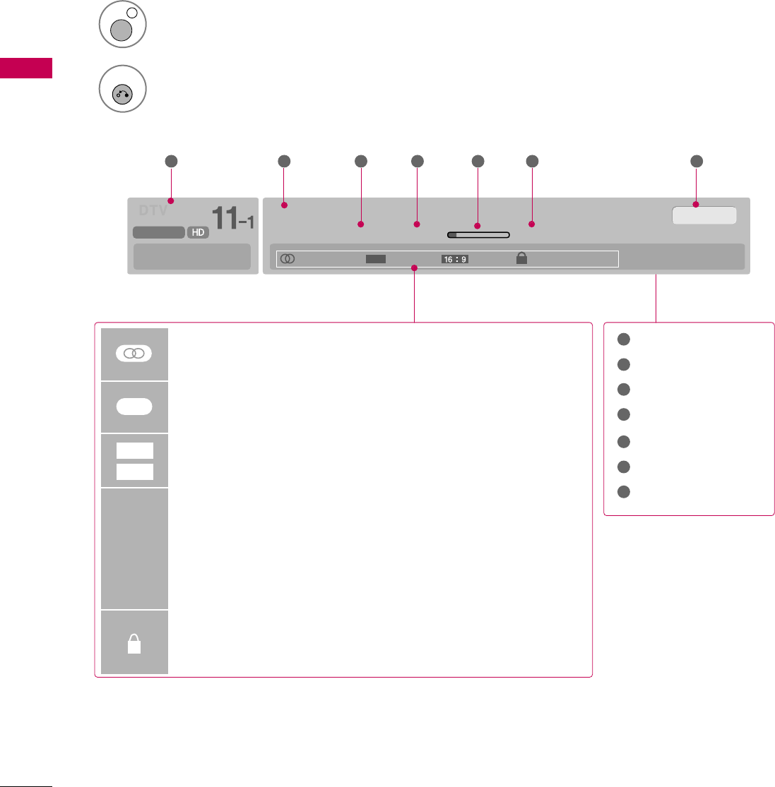
WATCHING TV / CHANNEL CONTROL
60
BRIEF INFORMATION
WATCHING TV / CHANNEL CONTROL
1
INFO i
Brief Info shows the present screen information.
Brief Info Title Test..
Sat, Feb 21, 2009 10:10 AM 11:40 AM
CNN
DOLBY DIGITAL
10:40 AM
Multilingual Caption 1080i TV-PG D L S V
CC
Program title
Day, Month, Year
Program start time
Program progress bar
Program finish time
Present time
Banner information
1 2 3 4 5 67
1
2
3
4
5
6
7
Multilingual : The program contains two or more audio services. Use
the Q.MENU menu to select wanted Audio.
Caption : The program contains one or more caption services. Use
the Q.MENU menu to select wanted Closed caption.
The original aspect ratio of the video is 4:3
The original aspect ratio of the video is 16:9 (wide)
The video resolution is 720x480i
The video resolution is 720x480p
The video resolution is 1280x720p
The video resolution is 1920x1080i
The video resolution is 1920x1080p
V-Chip: The program contains V-Chip information. Refer to the
LOCK menu: A (Age), D (Dialogue), L (Language), S (Sex), V
(Violence), FV (Fantasy Violence)
480i
480p
720p
1080 i
1080p
4:3
16:9
CC
Show the Brief Info on the screen.
2
RETURN
Return to TV viewing.