LG Electronics USA 9QK-CX8703IB JukeBlox Networked Media Module User Manual
LG Electronics USA JukeBlox Networked Media Module
UserManual.wiki
>
LG Electronics USA
>
9QK CX8703IB User Manual
User Manual
Navigation menu
Upload a User Manual
Namespaces
Wiki Guide
HTML
PDF
Info
Views
User Manual
Discussion / Help
Navigation
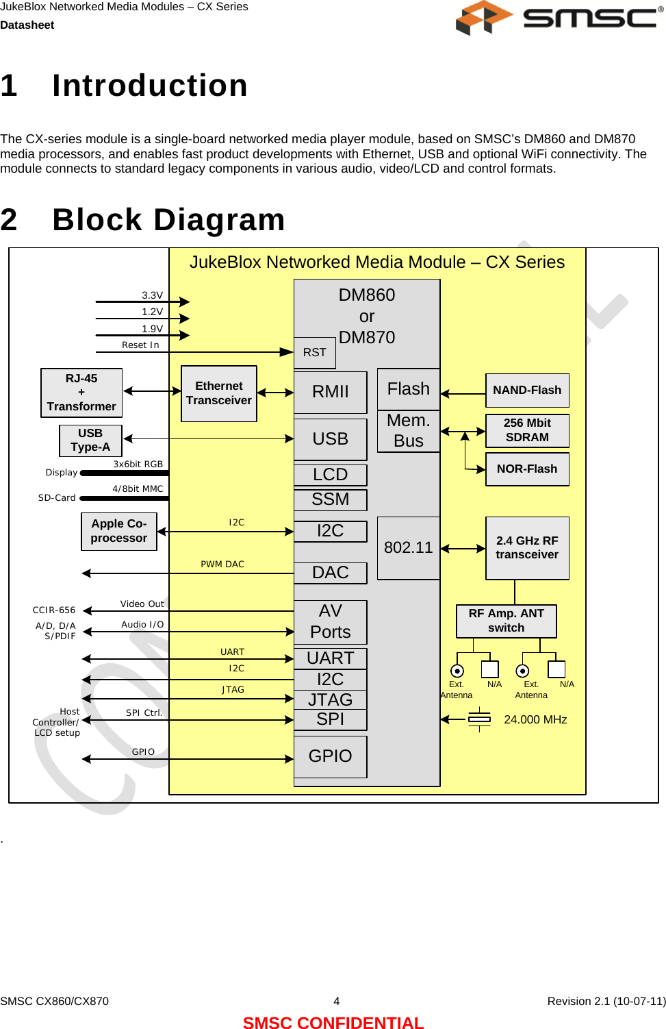
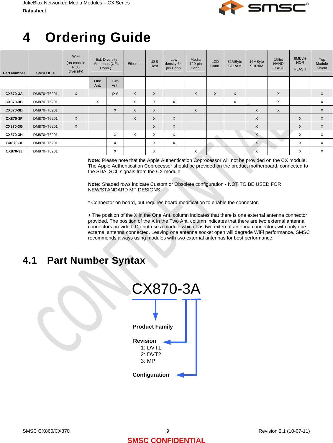
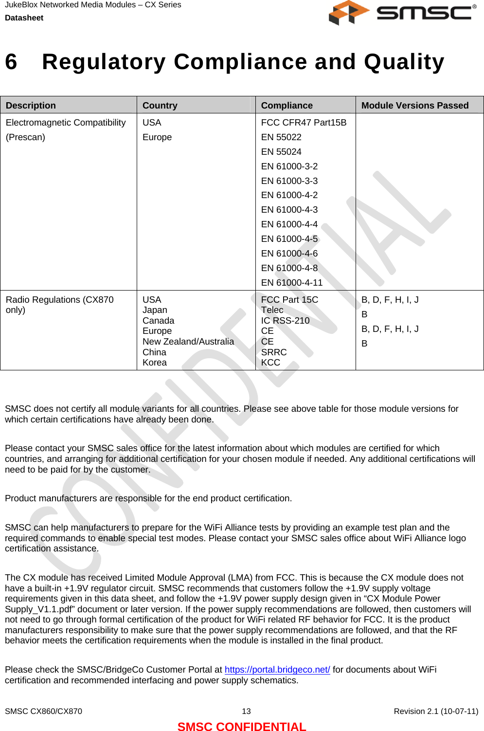
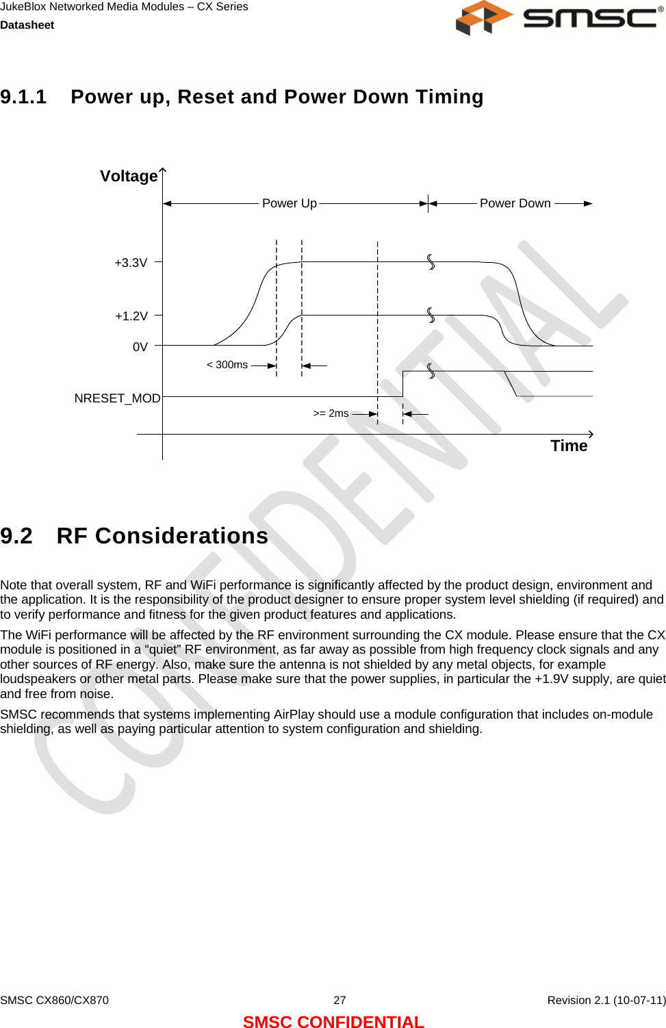
![JukeBlox Networked Media Modules – CX Series Datasheet SMSC CX860/CX870 14 Revision 2.1 (10-07-11) SMSC CONFIDENTIAL 6.0.1 Antenna Considerations Here are the antennas used for certification: CX870-3B 1$ Dipole, WINiZEN, WIE-WO-08, 3.2 dBi for 2.4GHz CX870-3D1$ FCC&IC: Inverted-F, Tyco Electronics, 2174241, 2.19 dBi for 2.4 GHz CE: Wanshih 01S0940-00, dipole, 1.59dBi@2.4GHz, 2.65dBi@2.45GHz, 1.76dBi@2.5GHz CX870-3F1$ Printed on PCB, Lite-On, N/A, 3.91 dBi for 2.4 GHz CX870-3H 1$Dipole, MAG.LAYERS, EDA-8709-2G4C1-A66, 2 dBi for 2.4GHz CX870-3I 1$Dipole, MAG.LAYERS, EDA-8709-2G4C1-A66, 2 dBi for 2.4GHz CX870-3J 1$Dipole, MAG.LAYERS, EDA-8709-2G4C1-A66, 2 dBi for 2.4GHz )RUWKLVGHYLFH01&;,%)&&,'%(-4.&;,%XVHVRQO\EHORZDQWHQQD3,)$$QWHQQD%ODFN/,7(2106$*&$G%LIRU*+]3,)$$QHQQD*UD\/,7(2106$*&$G%LIRU*+] Notes about antenna changes: 1) Equivalent antennas from other manufacturers may be substituted, and then marketed without a Class II permissive change 2) Equivalent antennas must be of the same type (e.g. dipole, PIFA, etc.), must be of equal or less gain than the antennas listed and previously authorized under the same FCC ID, and must have similar in band and out of band characteristics (consult specification sheet for cutoff frequencies). 3) In case of new antenna types, or higher gain antennas, a Class II permissive change is required and compliance with FCC section 15.203 must be met.](https://usermanual.wiki/LG-Electronics-USA/9QK-CX8703IB/User-Guide-1755767-Page-14.png)