LG Electronics USA 9QK-LW130W HD Compact Network Camera User Manual manual by monica
LG Electronics USA HD Compact Network Camera manual by monica
UserManual.wiki
>
LG Electronics USA
>
9QK LW130W User Manual
User Manual
Navigation menu
Upload a User Manual
Namespaces
Wiki Guide
HTML
PDF
Info
Views
User Manual
Discussion / Help
Navigation
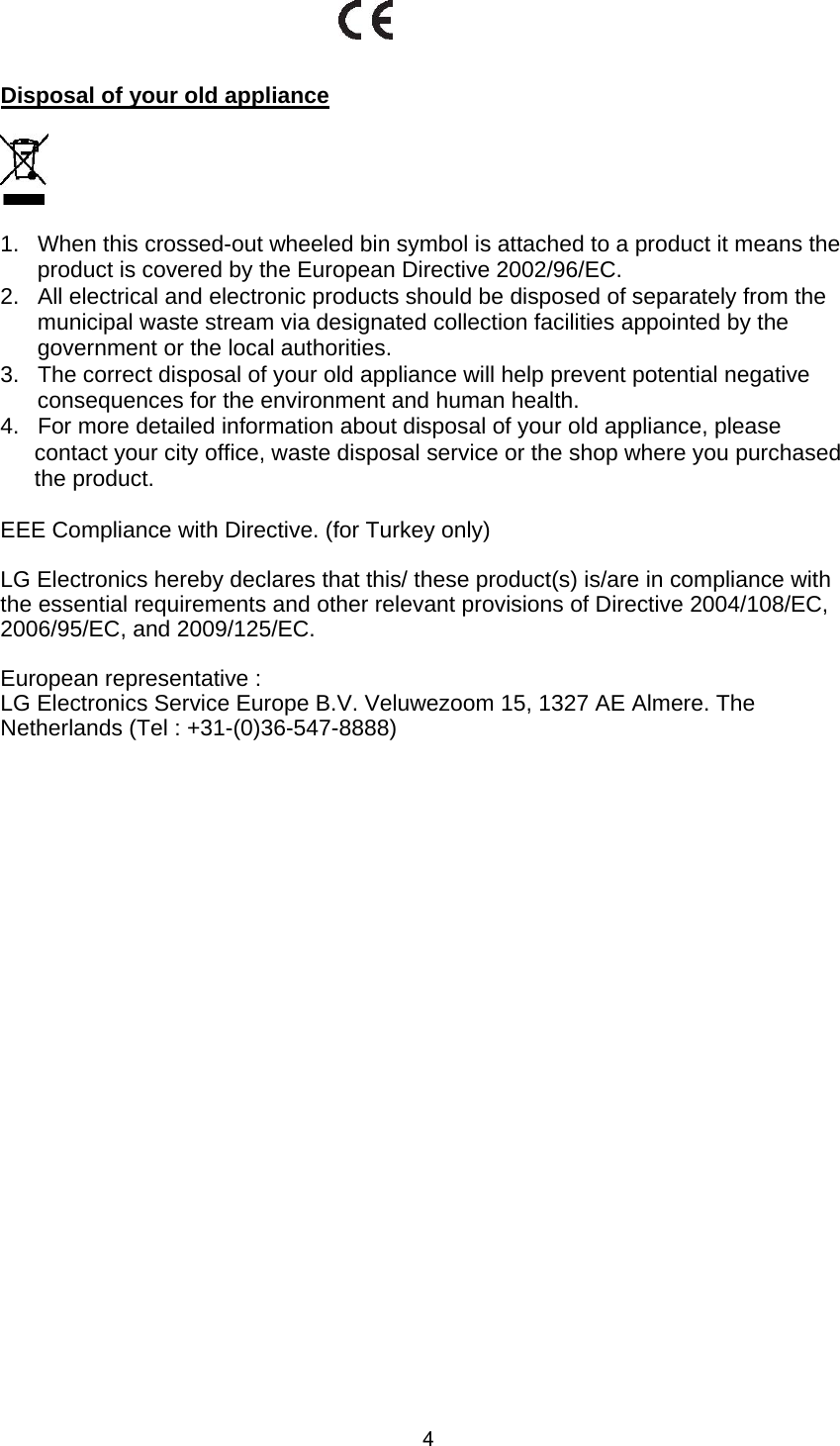
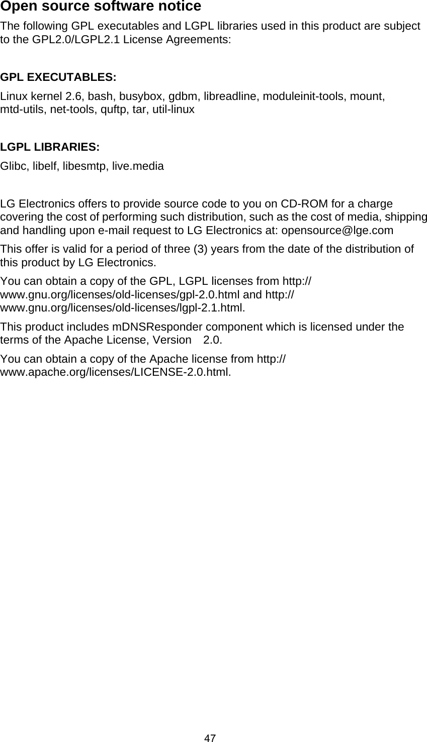
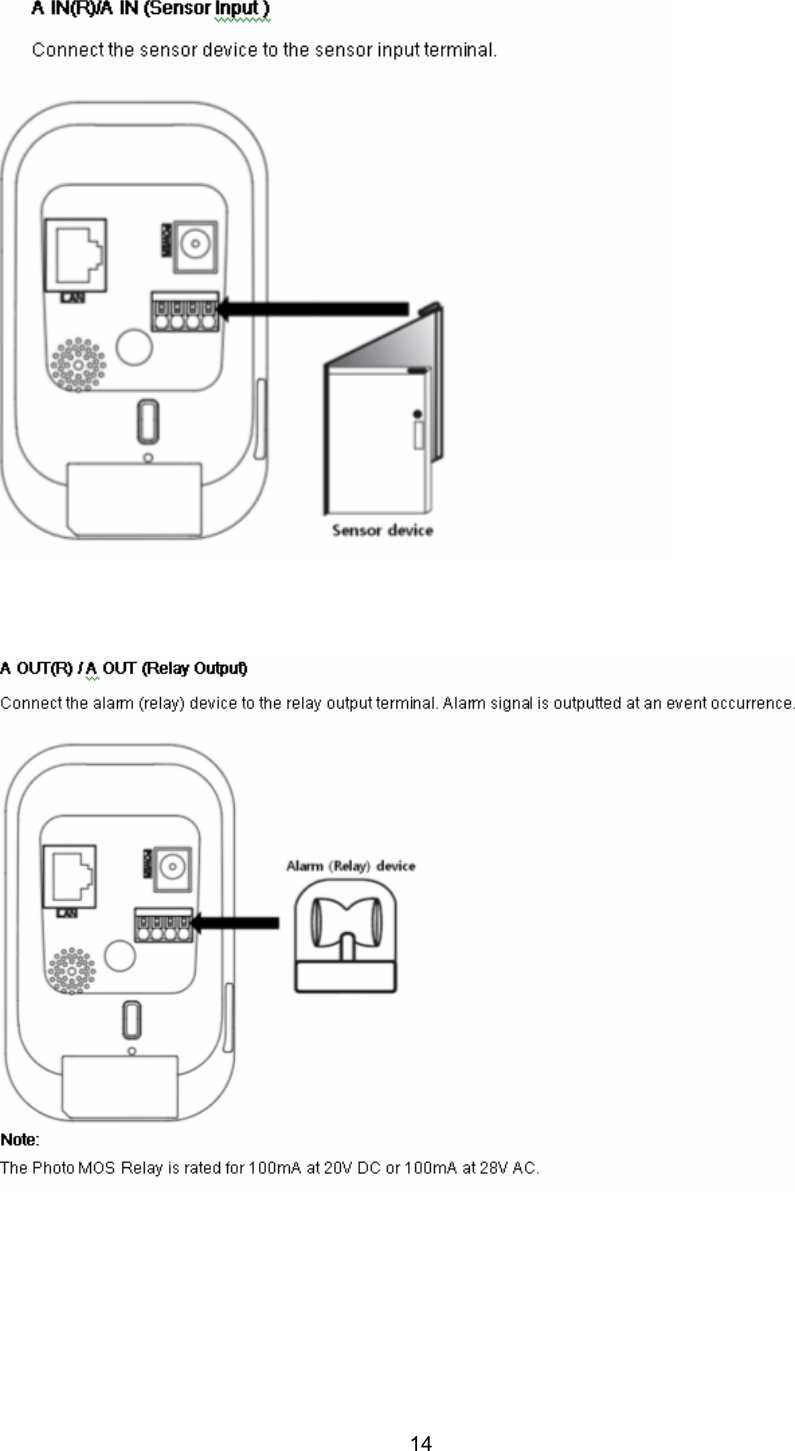
![13 Alarm terminals are used to connect the alarm (relay) devices such as sensors, door switches, etc. Specification of alarm terminal is shown as bellow. [Alarm terminal specification] Minimum Typical Maximum Note Digital Input 2.3V 3.3V 4.3V Digital Output 2.3V 3.3V AWG 24 AWG 16 UL Standard Connectable cable 0.20 mm2 1.5mm2 IEC Standard Absolute Maximum Ratings - Digital Input: -24V to +24VDC - Digital Output: +3V to +24VDC / 100mA Max Connect connectable cable to alarm terminal. While disconnecting, push A button.](https://usermanual.wiki/LG-Electronics-USA/9QK-LW130W/User-Guide-1549811-Page-13.png)
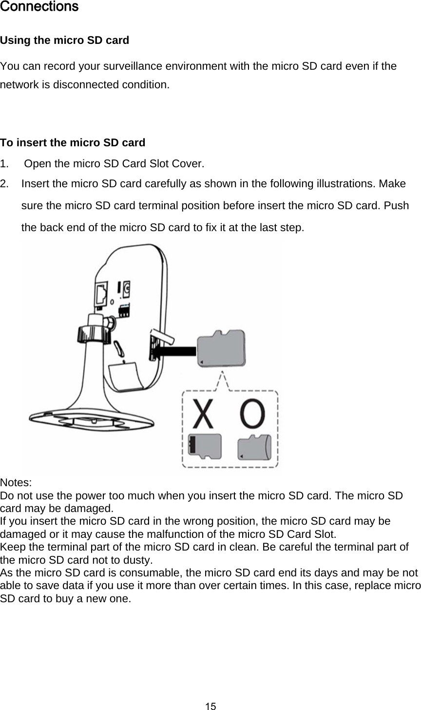
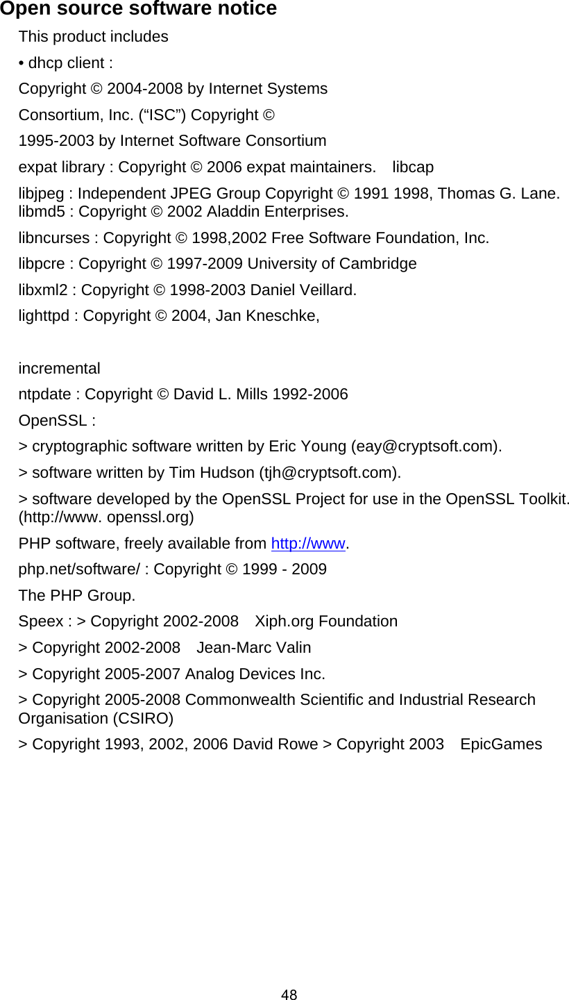
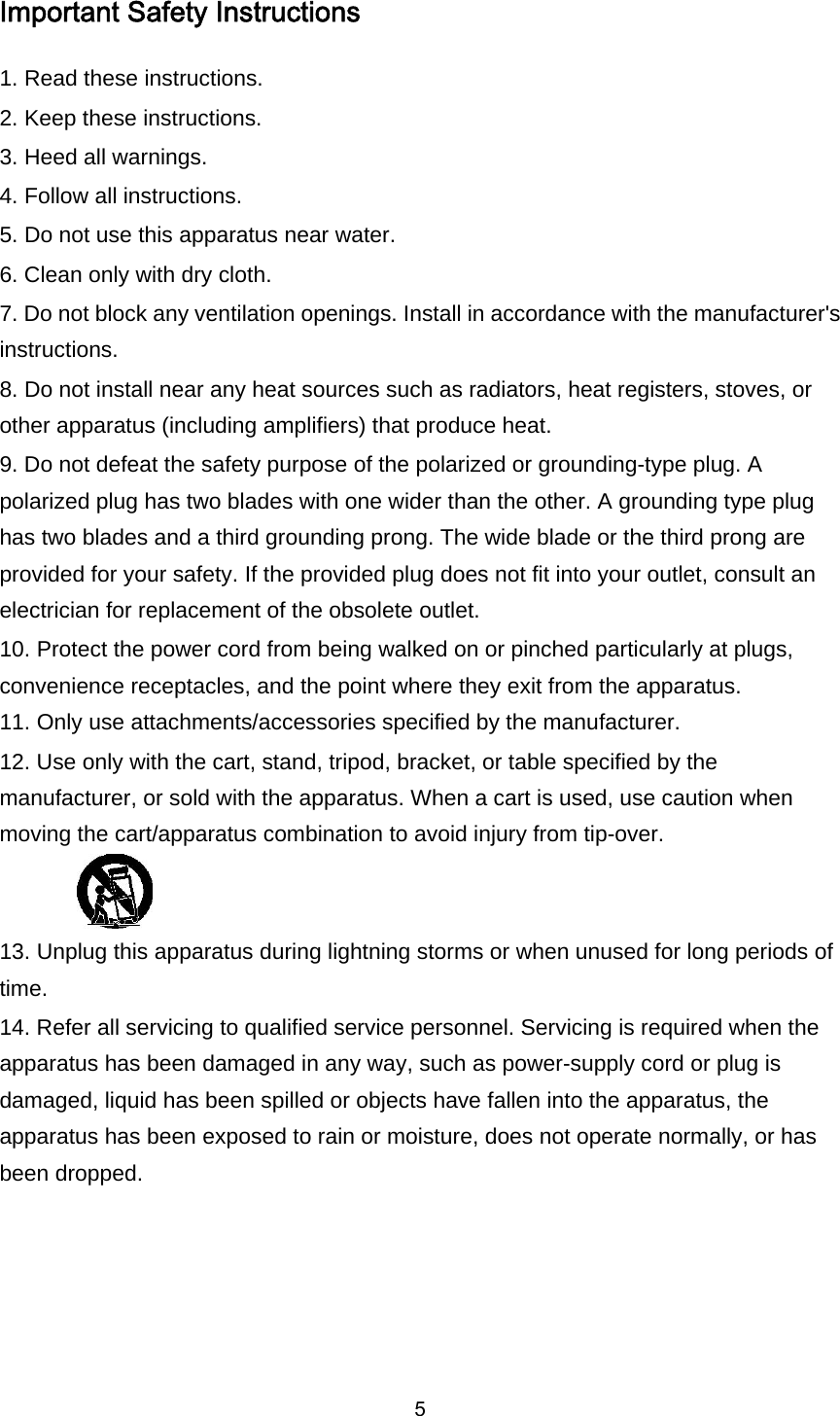
![16 Caution: If you install the micro SD card on the camera and remove the micro SD card during operation, you must unmount the micro SD card by using the [SD Card > Configuration > Disk Management > Unmount] menu. The micro SD card data is compromised or the camera may not operate normally, if you remove the card without use [Unmount] function. LG Electronics is not responsible for deleted data caused by user mishandling when you insert or remove the micro SD card. Recommended the micro SD card specification Manufacturer Capacity Block Size (FAT 32) Note LG Sandisk Transcend Less than 32 GB 32 kbyte Speed of reading and writing more than 10 MB/Second (Class 6)](https://usermanual.wiki/LG-Electronics-USA/9QK-LW130W/User-Guide-1549811-Page-16.png)
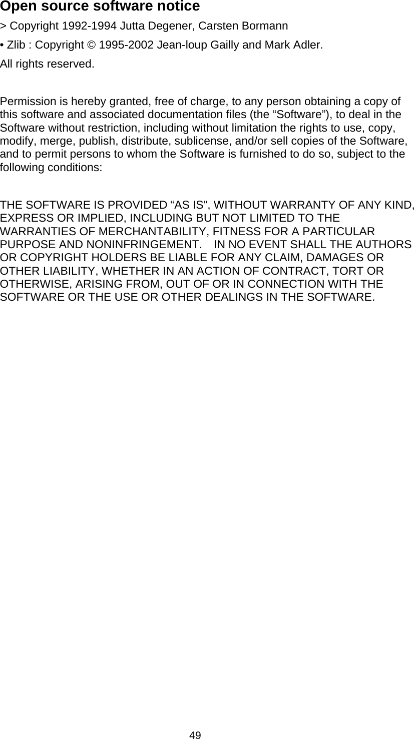
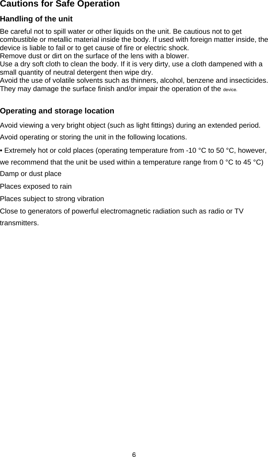
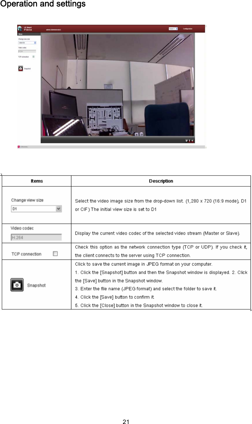
![19Operation and settings Recommended PC Requirements Accessing the LG IP device The LG IP device can be used with most standard operating systems. You can access the LG IP device by following the below systems and browsers. Steps: 1. Install LG Smart Station Program 2. Discover LG IP device using the IP Utility The IP Utility can automatically discover and display LG IP devices on your network. The IP Utility shows the MAC address, IP address, Model name and so on. Note: The computer running the IP Utility must be on the same network segment (physical subnet) as the LG IP device. 2.1 Run the IP Utility program. 2.2 Click the [Search] icon or select the [Search] option in the Device search menu. After a few seconds the found LG IP devices will be displayed in the IP Utility window. 3. Logging in to the LG Smart Web Viewer The LG Smart Web Viewer can be used with most web browsers. The recommended browser is Internet Explorer with Windows. 3.1 Run the IP Utility and find the LG IP devices. 3.2 When the LG IP devices appear in the IP Utility window, double-click IP address or right click on the same IP address and select "Connect to Web Page" to start the LG Smart Web Viewer. When accessing the LG Smart Web Viewer, the authentication dialog appears on the screen. 3.3 Enter the user name and password. (Note that the default administrator user name and password are “admin”.) 3.4 Click the [OK] button and then the LG Smart Web Viewer is displayed in your browser. Items Requirements Operating System Windows XP Professional, Windows VISTA, Windows 7 CPU Intel Core2 Quard Q6700 (2.66 GHz) or above Web Browser Microsoft Internet Explorer above the version 6.0 and below the version 8.0. DirectX DirectX 9.0 or above Memory 2 GB or above RAM Graphics Card 256 MB or above Video RAM Resolution 1 280 x 720 (with 32 bit color) or higher](https://usermanual.wiki/LG-Electronics-USA/9QK-LW130W/User-Guide-1549811-Page-19.png)
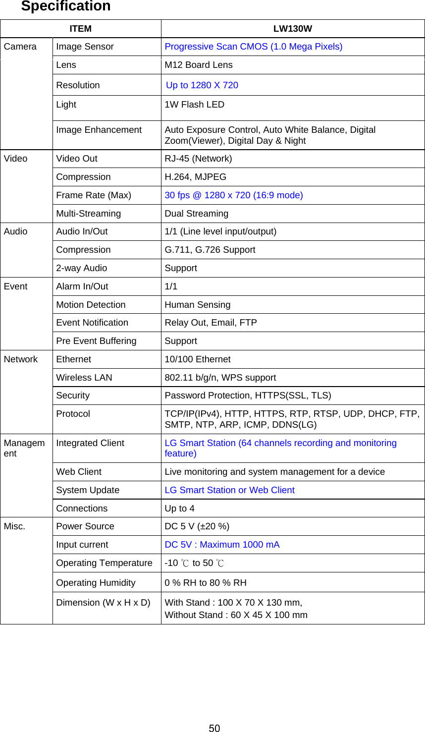
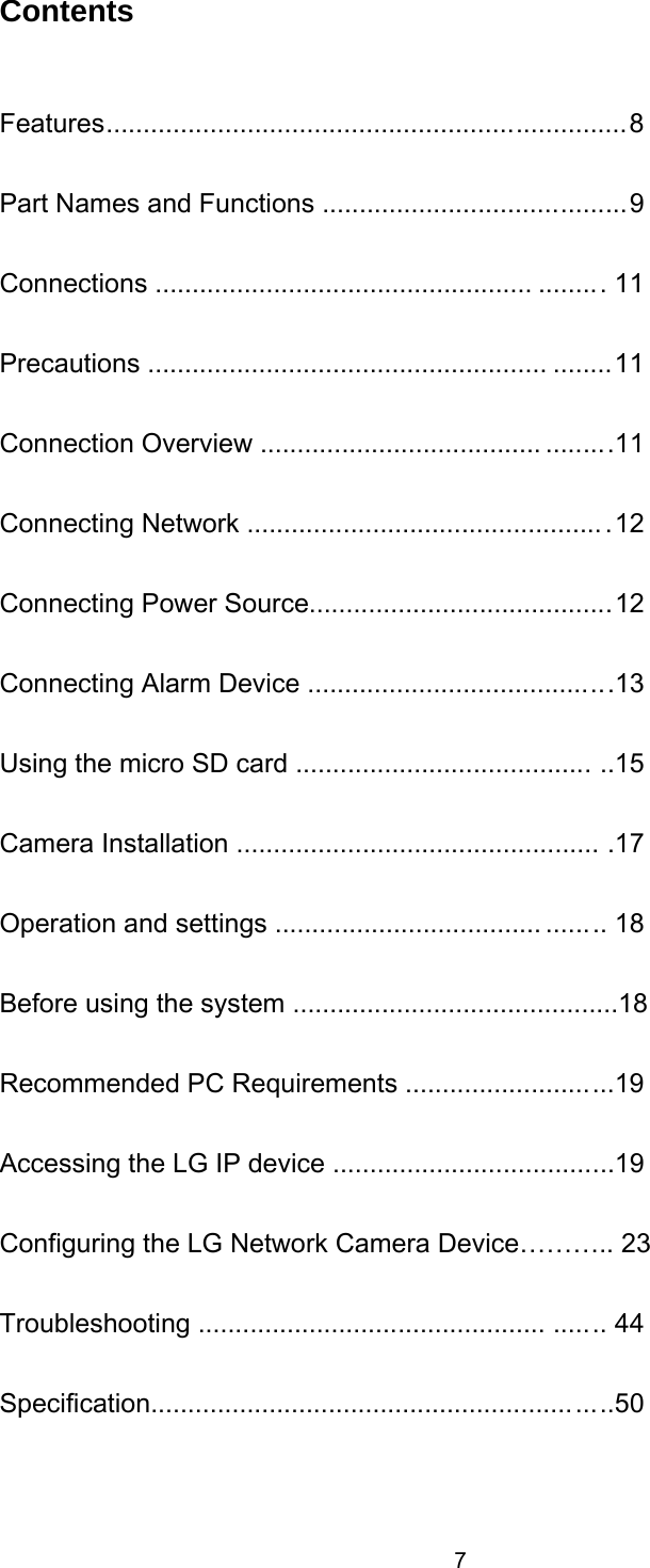
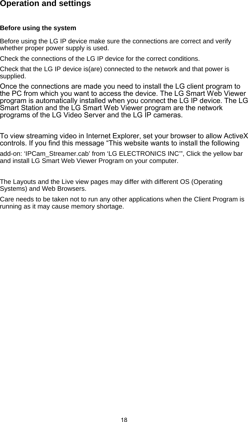
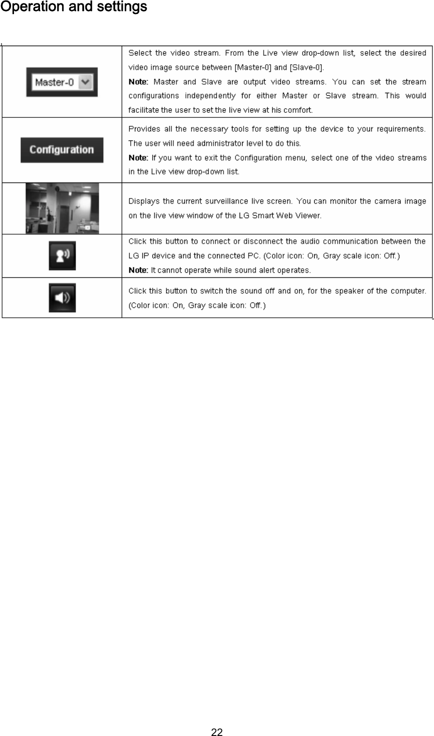
![20Notes: • You can also access the LG Smart Web Viewer as shown below. 3.1 Start your Web browser. 3.2 Enter the IP address of the LG IP device in the address bar of the browse. 3.3. Enter the user name and password set by the administrator. 3.4 Click the [OK] button and then the LG Smart Web Viewer is displayed in your browser. The LG Smart Web Viewer needs more time to display it according to the network conditions. If the login window is not displayed, check the pop-up blocker. If you set the pop-up blocker, the login window is not displayed. You must allow the pop-ups. If you connect the LG Smart Web Viewer for the first time, the Security Warning window is displayed to install the LG Smart Web Viewer program. You must install the LG Smart Web Viewer program for using the LG IP device. If your computer or network is protected by a proxy or firewall, the proxy or firewall settings can prevent the LG Smart Web Viewer program. Change the proxy or firewall settings to activate the LG Smart Web Viewer program.](https://usermanual.wiki/LG-Electronics-USA/9QK-LW130W/User-Guide-1549811-Page-20.png)
![23Configuring the LG Network Camera Device The features and options of the LG IP camera are configured through the Configuration menu. Only administrator-level users have permission to access the Configuration menu. Accessing the Configuration menu Click the [Configuration] button to display the LG Smart Web Viewer configuration window. Warning The Configuration setup should be made by qualified service personnel or system installers. Configuration menu overview The following table shows the list of menu items. Main menu Sub menu Version Date & Time Maintenance Log & Report System Language Camera Stream Audio Audio & Video Motion detect Basic RTP stream TCP/IP DDNS IP filtering Network Wireless User Basic SD card Basic Event scheduleEvent server Event Sensor & Relay](https://usermanual.wiki/LG-Electronics-USA/9QK-LW130W/User-Guide-1549811-Page-23.png)
![24Operation and settings Time zone Set the time difference from GMT in the area where the IP device is installed. Select the time zone in the area where the IP device is installed from the drop down list. Time mode > Synchronize with NTP Server: Select if you want to synchronize the IP device’s date and time with those of the time server called NTP (Network Time Protocol). Specify the NTP server’s name. Click the [Test] button for connection test to the server. > Synchronize with personal computer: Select if you want to synchronize the IP device’s date and time with your computer. > Synchronize manually: Select if you want to set the IP device’s date and time manually. Select the year, month and date by clicking the calendar button. Set hour, minutes and seconds in the edit boxes. Notes: • When system reboot after time setting, time of system could be delayed. If you set the time correctly, set the [Synchronize with NTP server] option. • Refer to NTP configuration as operation system of the Recording Server when the Recording Server use recording function and NTP server. Server time > Server time: Displays the current date and time of the IP device. • Save: Click this button to confirm the settings.](https://usermanual.wiki/LG-Electronics-USA/9QK-LW130W/User-Guide-1549811-Page-24.png)
![25Operation and settings Maintenance System reboot Click the [Reboot] button to restart the IP device. It takes some minutes for the IP device to start again. Backup and Restore > Backup: To take a backup all of the settings. If necessary, it make possible to return to a backup configuration. Click this button and follow the instructions on the browser to specify the folder and save the setting data of the IP device. This configuration backup can be restored whenever needed. > Restore: 1 Click the [Browse] button. 2 Find and open the file in which the configuration setting data is stored. 3 Click the [Restore] button and the system settings will be restored and reboot the system. Notes: • Backup and Restore can happen on IP device having the same version of firmware. This feature is not intended for multi-configurations or for firmware upgrades. • The [Backup] function is allowed in HTTP protocol but not in HTTPS protocol.](https://usermanual.wiki/LG-Electronics-USA/9QK-LW130W/User-Guide-1549811-Page-25.png)
![26Operation and settings Firmware > Upgrade 1 Click the [Browse] button. 2 Find and open the firmware file. 3 Click the [Upgrade] button to update the firmware. Note: When you upgrade the system, it may take some minutes to be done. Do not close the browser while the upgrade is in progress. If you close the browser, it may cause a malfunction. You should wait until the confirmation window is displayed. When the upgrade is finished, the confirmation window will be displayed. > Initialize: The [Initialize] button should be used with caution. Clicking it will return all of the IP device’s settings to the factory default values. (Except for Network settings, PTZ Protocol and Preset settings.) Log & Report Log & Report status The System log provides a summary of the status of the IP device. The unit records the data of the software activity in a file. > View Log: Click this button to display the system log information. > View report: Click this button to display the report of the system. Language Language list Select a language for the LG Smart Web Viewer configuration menu and information display. • Save: Click this button to confirm the settings.](https://usermanual.wiki/LG-Electronics-USA/9QK-LW130W/User-Guide-1549811-Page-26.png)
![27Operation and settings Audio & Video settings Camera Preview You can preview the camera image on the preview window. Operation and settings General > Contrast: Edit the contrast value from 0 to 100. Selecting 100 provides the image with the highest contrast. > Brightness: Edit the brightness of the camera. It is brighter when a large value is selected and it is darker when a small value is selected. > Standard: Displays the video standard of the camera. > Sharpness: Edit the sharpness value from 0 to 100. > BackLightCompensation: On or Off BackLightCompensation. > Exposure: Edit Exposure value. > Gain Control: Edit Gain control value. (Auto, x1, x2, x4, x8) > White Balance: Edit White balance value. (Auto, Indoor1, Indoor2) > Flickerless: Edit Flickerless value. (OFF, 60Hz, 50Hz) • Save: Click this button to confirm the settings. • Default: If you want to set the General setting to the default value, click the [Default] button and then click the [Save] button to confirm it.](https://usermanual.wiki/LG-Electronics-USA/9QK-LW130W/User-Guide-1549811-Page-27.png)
![28 Stream > Enable: Click to activate the stream function. > Video codec: Select the video mode (Codec) from the drop-down list. The viewer can choose between MJPEG and H.264. > Resolution: Select the image size to be sent from the camera. (1280 x 720 (16:9 mode), D1 (704 x 480), CIF (352 x 240)). > Maximum frame rate: Set the frame rate of the image. > GOP size: It means “Group of Pictures”. The higher the GOP, the better is the video quality of the camera. Edit the value of GOP from 1 to 30. This setting is valid for H.264 video format only. > Quality: Select the Quality. - VBR: The bit rate may vary depending on the complexity of the video to meet the selected quality. - CBR: The video quality may vary in order to preserve a constant bit rate. > Stream quality: If the [Quality] option set to VBR, this option is displayed. Select the stream quality from the drop down box, the camera supports five types (Highest, High, Medium, Low and Lowest) > Bit rate: If the [Quality] option set to CBR, this option is displayed. Edit the bit rate value from 256kbps to 10240kbps. Note: If the ‘Bit rate’ is configured too low with high resolution, the actual frame rate will decrease because of narrow bandwidth. So you need to set or change the ‘Bit rate’ to high value. • Save: Click this button to confirm the settings.](https://usermanual.wiki/LG-Electronics-USA/9QK-LW130W/User-Guide-1549811-Page-28.png)
![29Audio Audio In > Enable: Click the check box if you want to send the audio from the microphone input connector. Note: The Clients connected to the IP device remain unaffected with additional changes made in the setting. > Audio type: Select the codec when you send the audio from the microphone input connector. Audio Out > Enable: Click the check box to output the audio from the speaker. • Save: Click this button to confirm the settings. Preview You can preview the motion detection window on the preview window. General > Sensitivity: Enter the sensitivity to detect an object in motion. > Save: Click this button to confirm the settings. How to set the motion detect window 1 Click the [Add] button. The motion detect window is displayed. You can add the five windows maximum for motion detection area. 2 Set the [Sensitivity] option. 3 Click the edge or corner of the window box to adjust the window size for motion detection. 4 Click the [Save] button to save the settings. Notes: You can reset the window size. Click one of the window edge or corner and drag & drop to reset the motion detection area.](https://usermanual.wiki/LG-Electronics-USA/9QK-LW130W/User-Guide-1549811-Page-29.png)
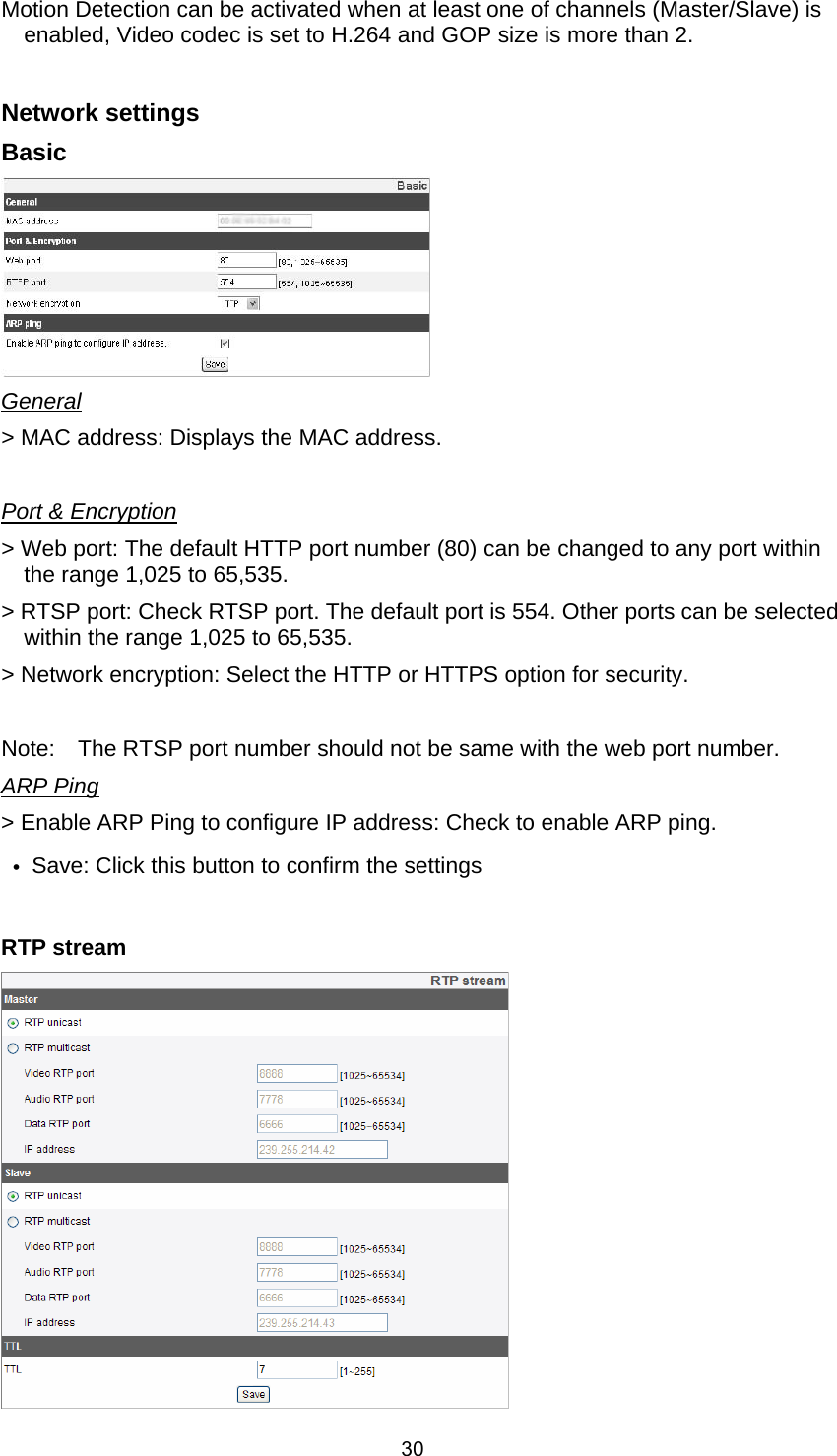
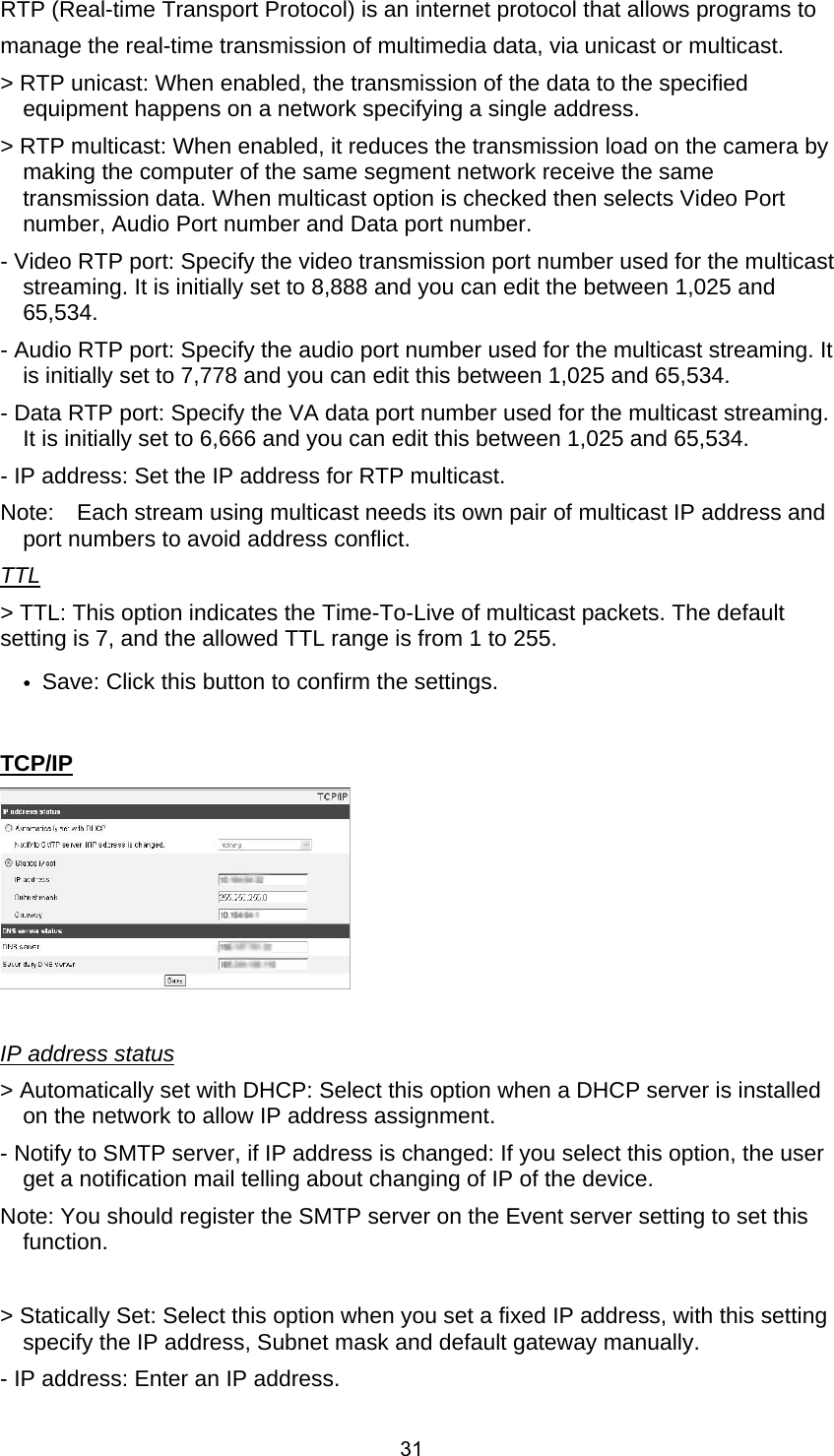
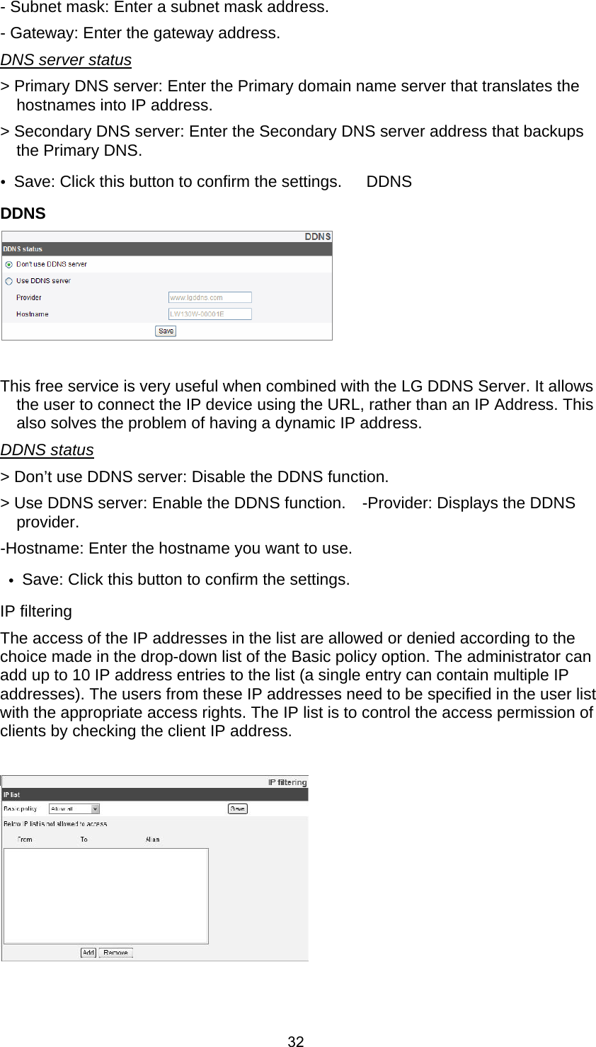
![33IP list > Basic policy: Select the basic policy type. - Allow all: Allow all the IP address basically, but the IP addresses in the list are denied. -Deny all: Deny all the IP address basically, but the IP addresses in the list are allowed. It needs at least one IP address to activate this function. Save: Click this button to confirm the settings. • Add: Click this button to add the IP address. 1. Click the [Add] button. 2. Set the IP options. -Alias: Enter the alias. -From: Enter the start IP address for the IP filtering. -To: Enter the end IP address for the IP filtering. Note: If you want to deny or to allow a range of IP addresses, enter the start IP address to "From" and the end IP address to "To". You can also add an IP address by entering the same IP address to "From" and "To". 3. Click the [Save] button. 4. Repeat the steps 1 to 3 to add additional IP address. Remove: Click this button to delete the IP address. 1 Select the alias from the list. 2 Click the [Remove] button. The IP address will be deleted. Wireless](https://usermanual.wiki/LG-Electronics-USA/9QK-LW130W/User-Guide-1549811-Page-33.png)
![34Access Point > Click [Refresh] button, display Access Points around. Left number describes signal strength of access point and Right describes name of access point. > Click [Info] button, show the detailed information of access point. > Click [Add Config] button, add access point to right window. > Click added access point of right window and [Connect] button, Wi-Fi starts connecting with selected AP. When connecting with AP, connection status is displayed and cha nged. (Connection status : connecting, IP assigning, connected, wps connected) > Click [Disconnect] button, Wi-Fi is disconnected with AP. Note: The camera user cannot edit, remove, and connect connected AP. > Click [Add] Button, add access point. > Click [Edit] Button, edit access point information. > Click [delete] Button, delete access point. IP address status > Automatically set with DHCP: Select this option when a DHCP server is installed on the network to allow IP address assignment. > Statically Set: Select this option when you set a fixed IP address, with this setting specify the IP address, Subnet mask and default gateway manually. - IP address: Enter an IP address. - Subnet mask: Enter a subnet mask address. - Gateway: Enter the gateway address. - Primary DNS server: Enter the Primary domain name server that translates the hostnames into IP address. - Secondary DNS server: Enter the Secondary DNS server address that backups the Primary DNS. • Save: Click this button to confirm the settings.](https://usermanual.wiki/LG-Electronics-USA/9QK-LW130W/User-Guide-1549811-Page-34.png)
![35User settings Basic The IP device is shipped with the login rights of administrator only. If others need to access the IP device excluding the configuration a login with viewer rights need to be created. A maximum of 50 users can be created. User list > Add the User You can register a new user with various access rights. 1. Click the [Add] button. User setting dialog is displayed. 2. Enter the new User ID and Password. (Should have a minimum of 4 characters and preferably a combination of alphanumeric). 3. To confirm the password, retype the password that you typed in the Password box. 4. Select the authority from the drop down list to provide the access rights to each user and then click the [Save] to confirm your selection. - Administrator: Allows you to operate setup menus and to view live images. - Power user: Use of the limited functions of the system (The Configuration menu is not allowed). A power user can use the Live View and audio functions. - Normal user: Provides the lowest level of access, Allows to view live images only. - Custom user: The user can login and view the live stream image only when the “Enable anonymous login” option is checked to enable it. Note: Remember the password. > Edit the registered user You can change the password or authority. 1. Choose the user ID and then click the [Edit] button. 2. Change the Password or Authority, then click the [Save] button to confirm your selection. > Delete the registered user 1. Choose the user ID you want to delete. 2. Click the [Remove] button.](https://usermanual.wiki/LG-Electronics-USA/9QK-LW130W/User-Guide-1549811-Page-35.png)
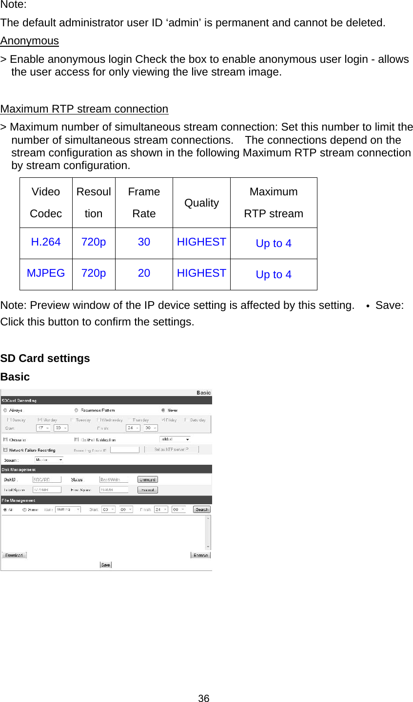
![37SD Card Recording > Always: Start the recording at once. > Recurrence Pattern: The recording is started according to the setting time of the selected day. Note: You cannot set the time for a day. It will start the recording for the selected day of the time. > Never: [Always] and [Recurrence Pattern] recording functions are not activated. > Overwrite: If the micro SD card has insufficient space and this option will be activated. It will overwrite the oldest data. > DiskFull Notification: Sends a warning e-mail to the SMTP server when the micro SD card has fully recorded. Select the SMTP server from the drop-down list. You should register the SMTP server on the Event server setting to set this function. > Network Failure Recording: Select the checkbox to activate the micro SD card recording function. If the system does not work with recording server, the system will record the data to the micro SD Card. When the system connects to the recording server again, the recorded data of the micro SD card will transfer to the recording server automatically. > Recording Server IP: Enter the recording server IP > Set as NTP server IP: Click this button to use the entered Recording Server IP as the NTP server IP > Stream: Select the stream type for the recording. Notes: The recorded file name is made automatically as the “[Created date of the file]_[GMT Recording Time]+(-)[Value of the Local Time minus GMT Time (Second)]_[Use or not of the Daylight saving time(N/D)] Disk Management > Using the micro SD card 1 Insert the micro SD card carefully to the micro SD card slot of the camera. 2 Click the [Mount] button. If the micro SD card is mounted to the system correctly, the [Mount] button will be changed to the [Unmount] button. 3 Displays the information of the [Disk ID], [Status], [Total Space] and [Free Space] options. Notes: When the micro SD card is mounted, you should format the micro SD card. After the micro SD card format is finished, you should click the [Mount] button to use it. When you use the micro SD card format function, it may not progress immediately. In this case, you should try it again after waiting a few minutes. > Remove the micro SD card 1 Click the [Unmount] button. If the micro SD card is unmounted from the system correctly, the [Unmount] button will be changed to the [Mount] button. 2 Remove the micro SD card from the micro SD card slot of the camera.](https://usermanual.wiki/LG-Electronics-USA/9QK-LW130W/User-Guide-1549811-Page-37.png)
![38 Note: When you use the Unmount function, it may not progress immediately. Operations such as recording of the system and reading of data are required stop time before the Unmount function is activated. You should try it again after waiting a few minutes. File Management Display the recorded file of the micro SD card on the list. Click the [Search] button to display the recorded file. The list will be updated when you click the [Search] button. > To view the recorded file of the micro SD card 1. Select the search option. -All: Search the all recorded files in the micro SD card. -Some: You can set the search condition by using the date and time options. 2. Click the [Search] button and then the search result is displayed on the list. > Download: You can download the recorded data of the list to your PC. Select a recorded file on the list and click the [Download] button. The two confirmation window is displayed. You should download the all files that the recorded file(*.DAT) and information file(*.INFO).](https://usermanual.wiki/LG-Electronics-USA/9QK-LW130W/User-Guide-1549811-Page-38.png)
![39 Notes: It is recommended to deactivate the [Overwrite] function before you download the file. When [Overwrite] function is activated, the downloading file might be overwritten, if the micro SD card has insufficient space. The downloaded file can be played by using the LG Smart Station player. > Remove: Delete file from the SD card. • Save: Click this button to confirm the settings. Event settings Event schedule When an event (VA/Motion detect/Sensor event) occurs, this unit records the live images and routes as configured. Event schedule list >To edit the Event Schedule 1. Select the Trigger event and click the [Edit] button. Event schedule window is displayed. 2. Set the options.](https://usermanual.wiki/LG-Electronics-USA/9QK-LW130W/User-Guide-1549811-Page-39.png)
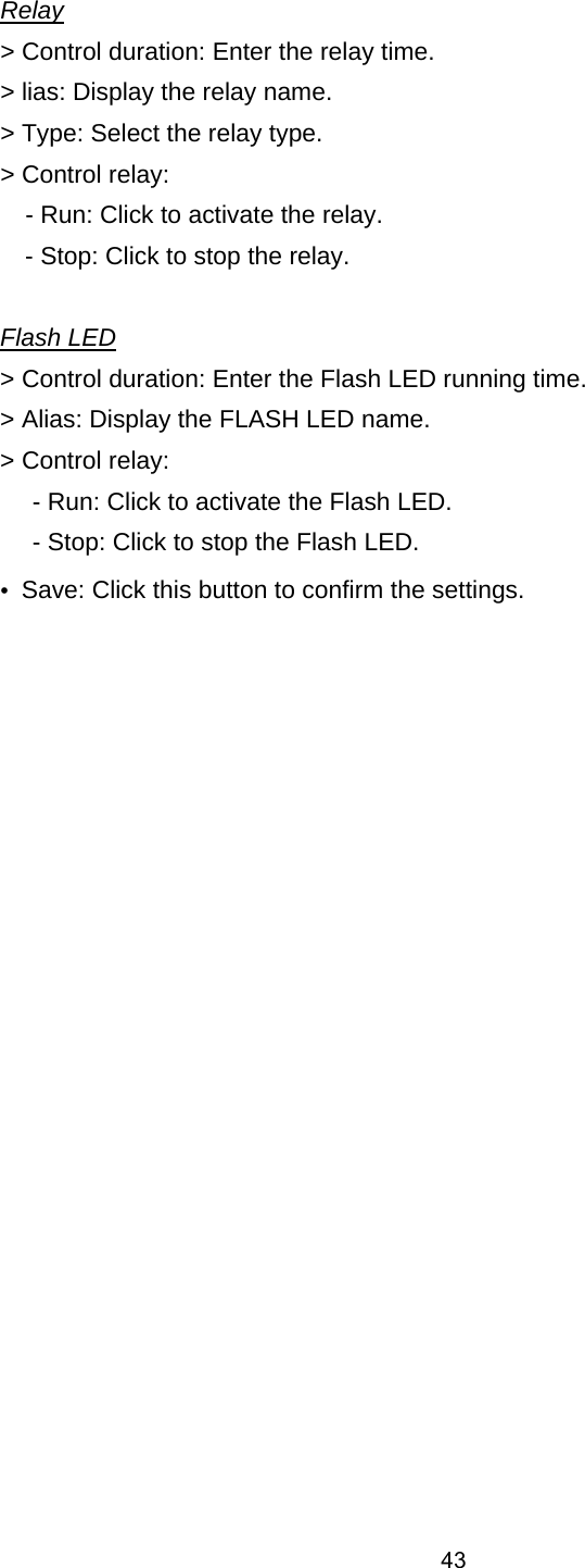
![40Trigger: Displays the selected trigger event. Time: Sets the Day, Start, Finish, Pre alarm, Post alarm and Ignore interval time options. Action: Selects the options. This occurs when the event runs. -FTP server/SMTP server: Uploading of images to an FTP server, or e-mail notification. -Control relay: The relay is activated or deactivated. -SDCard recording: Record on the SD card when the event runs. -Flash LED: Flash on when the event runs. -Sound Alert: Sound Alert on when the event runs. • Stream: Selects the stream of the connected camera. 3. Click the [Save] button to confirm the settings. Notes: You should register the SMTP and FTP server on the Event server setting to set this function. Recording of event (VA/Motion detect/ Sensor event) runs every 5 minutes split file. If the capacity of the SD card remains less than 200 MB, stop recording or overwrite new file after delete old one as [Overwrite] setting. The overwritten file cannot play or may malfunction when you download. Recorded file on the SD card, is recording 1 frame per second when set video codec to MJPEG. Event Server FTP server list Event Servers are used to receive the recorded video clip. > To add the FTP server 1 Click the [Add] button. FTP server setting window is displayed. 2 Set the FTP server options. - Alias: Type the FTP Server name to upload the image files. - Address: Enter the FTP server’s IP address.](https://usermanual.wiki/LG-Electronics-USA/9QK-LW130W/User-Guide-1549811-Page-40.png)
![41- Port: Enter the port number. The default FTP port is 21. - User ID: Type the user name for the Folder shared in the FTP server. - Password: Type the password for the folder shared in the FTP Server. - Folder: Type the path with the folder that is shared in the FTP server. -Test: Click [Test] button to test the FTP server. 3. Click the [Save] button to confirm the settings. > To edit the FTP server 1 Choose the FTP server in the FTP server list. 2 Click the [Edit] button. You can check or edit the FTP server options. > To delete the FTP server 1 Choose the FTP server in the FTP server list. 2 Click the [Remove] button. This would remove the FTP server from the list. SMTP server list By selecting the e-mail option, a still image of the event is captured and an e-mail with the attached image file is sent to the specified mail address. > To add the SMTP server 1 Click the [Add] button. SMTP server setting window is displayed. 2. Set the SMTP server options. - Alias: Enter the SMTP server name. - User ID: Enter the user ID of the SMTP server. This would be the one who owns the mail account. - Password: Enter the password of the SMTP server. - Address: Enter the SMTP server address. - Port: Enter the port number. The default port is 25. - Enable SSL: Check when use the SSL (Secure Socket Layer) protocol. SSL protocol is cryptographic protocols that provide secure communication on a network.](https://usermanual.wiki/LG-Electronics-USA/9QK-LW130W/User-Guide-1549811-Page-41.png)
![42 - Receiving address: Type the recipients e-mail address. You can specify only one recipient e-mail address. - Administrator address: Type the e-mail address of the administrator. - Subject: Enter the subject/title of the e-mail. - Message: This message can describe the information of the acquired IP address, etc. - Test: Click [Test] button to test the SMTP server. 3. Click the [Save] button to confirm the settings. > To edit the SMTP server 1 Choose the SMTP server in the SMTP server list. 2 Click the [Edit] button. You can check or edit the SMTP server options. > To delete the SMTP server 1 Choose the SMTP server in the SMTP server list. 2 Click the [Remove] button. Sensor & Relay Sensor > Enable: Mark up when you want to activate the sensor. > Alias: Display the sensor name. > Type: Select the sensor type. IR Motion Sensor > Enable: Mark up when you want to activate the IR motion sensor. > Alias: Display the IR motion sensor name.](https://usermanual.wiki/LG-Electronics-USA/9QK-LW130W/User-Guide-1549811-Page-42.png)