LG Electronics USA 9QK-LW130W HD Compact Network Camera User Manual manual by monica
LG Electronics USA HD Compact Network Camera manual by monica
User Manual

1
OWNER'S MANUAL
HD Compact Network Camera
Please read this manual carefully before operating your
set and retain it for future reference.
MODEL
LW130W

2
CAUTION: TO REDUCE THE RISK OF ELECTRIC SHOCK DO NOT REMOVE
COVER (OR BACK) NO USER-SERVICEABLE PARTS INSIDE REFER
SERVICING TO QUALIFIED SERVICE PERSONNEL.
This lightning flash with arrowhead symbol within an equilateral triangle is intended to
alert the user to the presence of uninsulated dangerous voltage within the product’s
enclosure that may be of sufficient magnitude to constitute a risk of electric shock to
persons.
The exclamation point within an equilateral triangle is intended to alert the user to
the presence of important operating and maintenance (servicing) instructions in the
literature accompanying the product.
FCC WARNING: This equipment may generate or use radio frequency energy.
Changes or modifications to this equipment may cause harmful interference unless
the modifications are expressly approved in the instruction manual. The user could
lose the authority to operate this equipment if an unauthorized change or modification
is made.
REGULATORY INFORMATION: FCC Part 15
This product complies with FCC Part 15B, Class B Limits: This device complies with
part 15 of the FCC Rules. Operation is subject to the following two conditions: (1) This
device must not cause harmful interference, and (2) this device must accept any
interference received, including interference that may cause undesired operation.
Radiated Energy
Note: This equipment has been tested and found to comply with the limits
for a Class B digital device pursuant to Part 15 of FCC Rules. These
limits are designed to provide reasonable protection against harmful
interference in a residential installation. This equipment generates, uses
and can radiate radio frequency energy and, if not installed and used in
accordance with instructions, may cause harmful interference to radio or
television reception, which can be determined by turning the equipment
off and on. The user is encouraged to try to correct the interference by one
or more of the following measures:
- Reorient or relocate the receiving antenna.
3
- Increase the separation between the equipment and the receiver.
- Connect the equipment into an outlet on a circuit different from that to
which the receiver is connected.
- Consult the dealer or an experienced radio/TV technician for help.
Changes and modifications not expressly approved by the manufacturer
or registrant of this equipment can void your authority to operate this
equipment under Federal Communications Commission rules.
• A suitable conduit entries, knock-outs or glands shall be provided in the cable entries
of this product in the end user.
1. To comply with FCC RF exposure compliance requirements, a
separation distance of at least 20 cm must be maintained between the
antenna of this device and all persons.
2. This Transmitter must not be co-located or operating in conjunction
with any other antenna or transmitter
Caution: Danger of explosion if battery is incorrectly replaced. Replaced only with the
same or equivalent type recommended by the manufacturer. Dispose of used
batteries according to the manufacturer’s instructions.
Holes in metal, through which insulated wires pass, shall have smooth well rounded
surfaces or shall be provided with brushings.
This Class B digital apparatus complies with Canadian ICES-003. Cet appareil
numÈrique de la classe B est conforme ‡ la norme NMB-003 du.
Warning: Do not install this equipment in a confined space such as a bookcase or
similar unit.
Warning: Wiring methods shall be in accordance with the National Electric Code,
ANSI/NFPA 70.
Warning: This is a class B product. In a domestic environment this product may
cause radio interference in which case the user may be required to take adequate
measures.
Warning: To reduce a risk of fire or electric shock, do not expose this product to rain
or moisture.
Caution: This installation should be made by a qualified
Service person and should conform to all local codes.
Caution: To avoid electrical shock, do not open the cabinet. Refer servicing to
qualified personnel only.
Caution: The apparatus shall not be exposed to water (dripping or splashing) and no
objects filled with liquids, such as vases, shall be placed on the apparatus.
To disconnect power from mains, pull out the mains cord plug. When installing the
product, ensure that the plug is easily accessible.

4
Disposal of your old appliance
1. When this crossed-out wheeled bin symbol is attached to a product it means the
product is covered by the European Directive 2002/96/EC.
2. All electrical and electronic products should be disposed of separately from the
municipal waste stream via designated collection facilities appointed by the
government or the local authorities.
3. The correct disposal of your old appliance will help prevent potential negative
consequences for the environment and human health.
4. For more detailed information about disposal of your old appliance, please
contact your city office, waste disposal service or the shop where you purchased
the product.
EEE Compliance with Directive. (for Turkey only)
LG Electronics hereby declares that this/ these product(s) is/are in compliance with
the essential requirements and other relevant provisions of Directive 2004/108/EC,
2006/95/EC, and 2009/125/EC.
European representative :
LG Electronics Service Europe B.V. Veluwezoom 15, 1327 AE Almere. The
Netherlands (Tel : +31-(0)36-547-8888)

5
Important Safety Instructions
1. Read these instructions.
2. Keep these instructions.
3. Heed all warnings.
4. Follow all instructions.
5. Do not use this apparatus near water.
6. Clean only with dry cloth.
7. Do not block any ventilation openings. Install in accordance with the manufacturer's
instructions.
8. Do not install near any heat sources such as radiators, heat registers, stoves, or
other apparatus (including amplifiers) that produce heat.
9. Do not defeat the safety purpose of the polarized or grounding-type plug. A
polarized plug has two blades with one wider than the other. A grounding type plug
has two blades and a third grounding prong. The wide blade or the third prong are
provided for your safety. If the provided plug does not fit into your outlet, consult an
electrician for replacement of the obsolete outlet.
10. Protect the power cord from being walked on or pinched particularly at plugs,
convenience receptacles, and the point where they exit from the apparatus.
11. Only use attachments/accessories specified by the manufacturer.
12. Use only with the cart, stand, tripod, bracket, or table specified by the
manufacturer, or sold with the apparatus. When a cart is used, use caution when
moving the cart/apparatus combination to avoid injury from tip-over.
13. Unplug this apparatus during lightning storms or when unused for long periods of
time.
14. Refer all servicing to qualified service personnel. Servicing is required when the
apparatus has been damaged in any way, such as power-supply cord or plug is
damaged, liquid has been spilled or objects have fallen into the apparatus, the
apparatus has been exposed to rain or moisture, does not operate normally, or has
been dropped.
6
Cautions for Safe Operation
Handling of the unit
Be careful not to spill water or other liquids on the unit. Be cautious not to get
combustible or metallic material inside the body. If used with foreign matter inside, the
device is liable to fail or to get cause of fire or electric shock.
Remove dust or dirt on the surface of the lens with a blower.
Use a dry soft cloth to clean the body. If it is very dirty, use a cloth dampened with a
small quantity of neutral detergent then wipe dry.
Avoid the use of volatile solvents such as thinners, alcohol, benzene and insecticides.
They may damage the surface finish and/or impair the operation of the device.
Operating and storage location
Avoid viewing a very bright object (such as light fittings) during an extended period.
Avoid operating or storing the unit in the following locations.
• Extremely hot or cold places (operating temperature from -10 °C to 50 °C, however,
we recommend that the unit be used within a temperature range from 0 °C to 45 °C)
Damp or dust place
Places exposed to rain
Places subject to strong vibration
Close to generators of powerful electromagnetic radiation such as radio or TV
transmitters.
7
Contents
Features......................................................................8
Part Names and Functions .........................................9
Connections ................................................... ......... 11
Precautions ...................................................... ........11
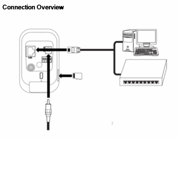
Connection Overview ...................................... .........11
Connecting Network ................................................ .12
Connecting Power Source.........................................12
Connecting Alarm Device .........................................13
Using the micro SD card ........................................ ..15
Camera Installation ................................................. .17
Operation and settings .................................... ........ 18
Before using the system ............................................18
Recommended PC Requirements ............................19
Accessing the LG IP device ......................................19
Configuring the LG Network Camera Device……….. 23
Troubleshooting ............................................... ....... 44
Specification..............................................................50
8
Features
The LG Network Camera is designed to use on an Ethernet and Wireless network and must
be assigned an IP address to make it accessible.
This manual contains instructions on how to install and manage the LG Network Camera in
your networking environment. Some knowledge of networking environments would be
beneficial to the reader.
Should you require any technical assistance, please contact authorized service center.
Dual H.264 Stream for single Video Input
Multi-Codec (H.264, MJPEG) Streaming
Audio Support (G.711, G.726 Full Duplex)
Ethernet 100Mbps
Wireless LAN 802.11b/g/n
Digital IN/OUT: Input 1port, Output 1port
MicroSD Memory extension (~32GB)
Pre/Post Alarm support
Human motion detection support
Flash LED (5meter)
AW, AE, AG support
9
Part Names and Functions
Part Names and Functions
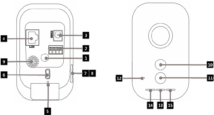
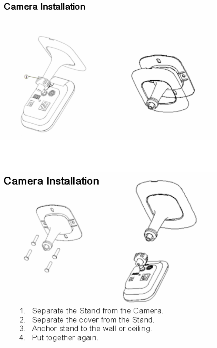
① Camera installation hole
Use this hole to install the camera on the wall or ceiling.
② External device connectors
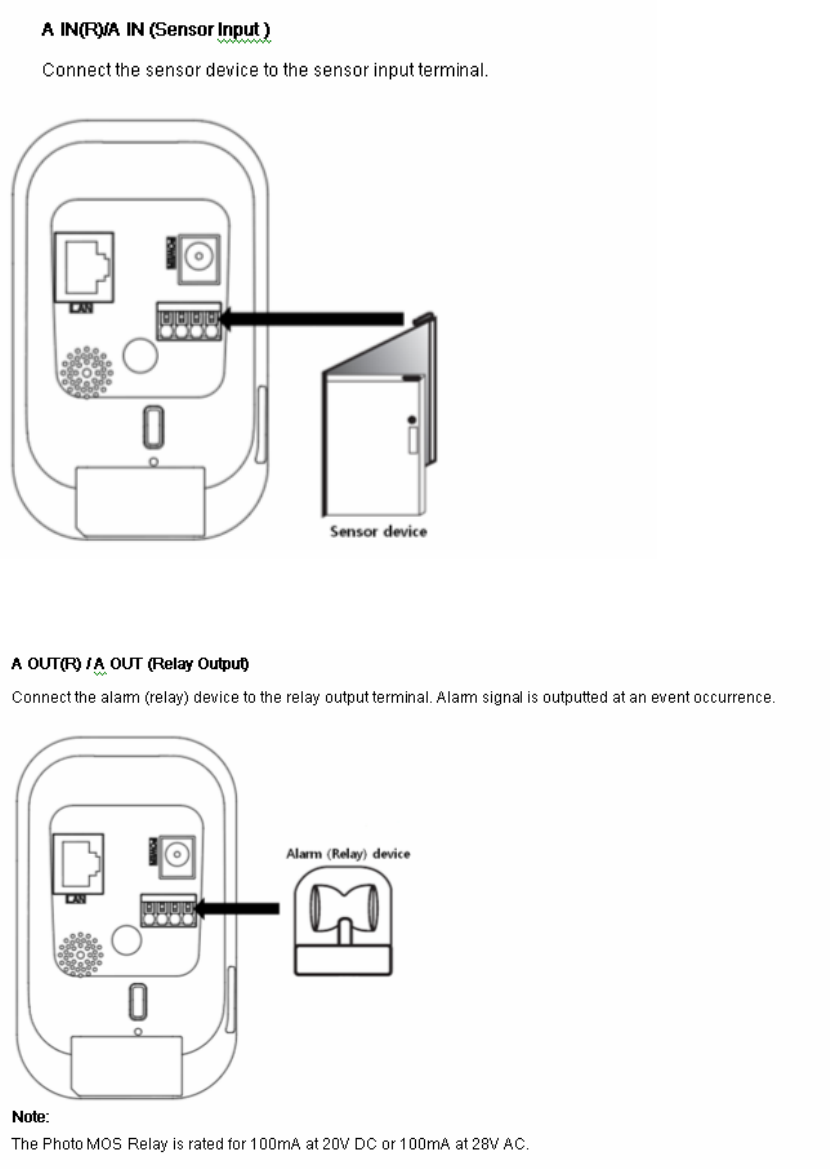
A IN(R)/A IN (Sensor input) Terminals: Provide physical interface for sensor.
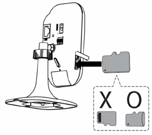
A OUT(R)/A OUT (Relay output) Terminals: Provide physical interface for Alarm/Relay.
③ Power source terminal
Connect to a DC 5V power supply using proper cables.
④ ETHERNET
Connect to a PC or a network via a hub with a 10 BASE-T/100 BASE-TX cable
attached RJ-45 connector
⑤ RESET button
Push the button, this would restart the device.
⑥ WPS(Wi-Fi Protected Setup), Factory Reset button
Push the button to use WPS or Factory Reset Function.
Push the button less than 4 seconds, this would trigger WPS.Push the button more than 10
seconds and Pop the button, this would trigger Factory Reset. When connecting AP using WPS,
wireless LAN connection lamp blinks red and green. When it stops blinking and color of it is
green, connection is completed. When it stops blinking and color of it is red, connection is failed.
Note:
Usage of WPS refers to the internet or access pointer manual. If access point sets
shared mode, you cannot connect access point using WPS.
10
⑦ Micro SD Card slot cover
⑧ Micro SD Card slot
Insert micro SD card.
⑨ Speaker
Transmit Mic sound of PC.
⑩ Motion detection sensor
Detect movement around.
⑪ Flash LED
Light on when event is occurred.
⑫ Mic
Listen sound of camera surround.
⑬ Power indicator
The Green LED lights when the camera is powered.
⑭ Ethernet connection indicator
The Green LED lights when the Ethernet is connected.
⑮ Wireless LAN connection indicator
The Green LED lights when the Wireless LAN is connected.
11
Connections
Precautions
Be sure to switch off the unit before installation and connection. The installation
should be made by qualified service personnel or system installers. Do not expose
the power and connection cables to moisture, which may cause damage to the unit.
12
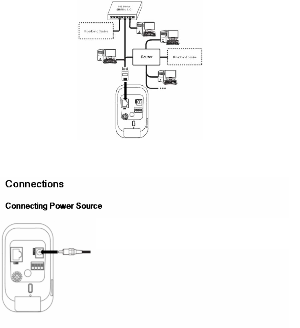
Connections
Connecting Network
You can control and monitor the system via network. With the remote control
(monitoring), you can change the system configuration or monitor the image via
network.
Connect to the DC 5 V UL Listed, Class 2 Power Supply only on the
unit. (Recommended power adapter is DC 5V/1.5A or above)
13
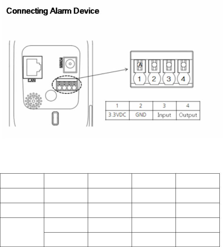
Alarm terminals are used to connect the alarm (relay) devices such as sensors, door switches,
etc. Specification of alarm terminal is shown as bellow.
[Alarm terminal specification]
Minimum Typical Maximum Note
Digital Input 2.3V 3.3V 4.3V
Digital Output 2.3V 3.3V
AWG 24 AWG 16 UL Standard Connectable
cable 0.20 mm2 1.5mm2 IEC Standard
Absolute Maximum Ratings
- Digital Input: -24V to +24VDC
- Digital Output: +3V to +24VDC / 100mA Max
Connect connectable cable to alarm terminal.
While disconnecting, push A button.
14
15
Connections
Using the micro SD card
You can record your surveillance environment with the micro SD card even if the
network is disconnected condition.
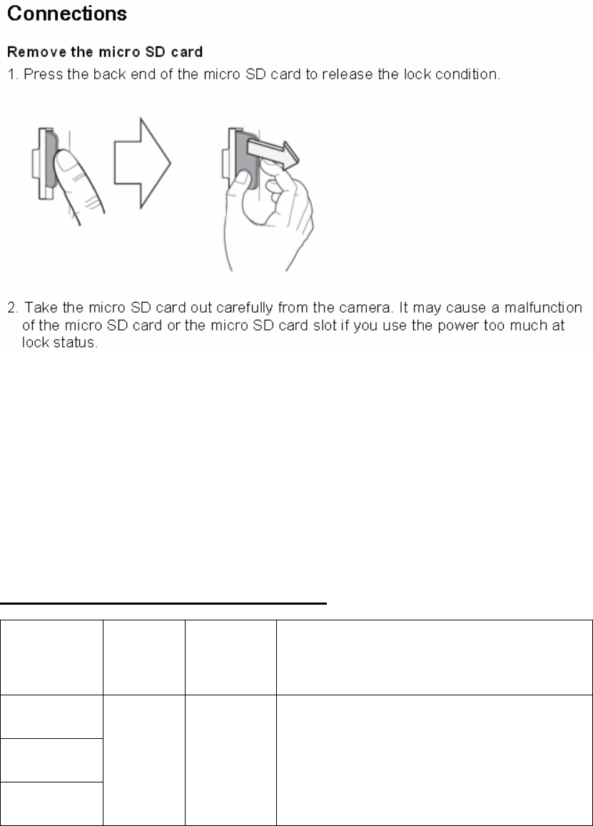
To insert the micro SD card
1. Open the micro SD Card Slot Cover.
2. Insert the micro SD card carefully as shown in the following illustrations. Make
sure the micro SD card terminal position before insert the micro SD card. Push
the back end of the micro SD card to fix it at the last step.
Notes:
Do not use the power too much when you insert the micro SD card. The micro SD
card may be damaged.
If you insert the micro SD card in the wrong position, the micro SD card may be
damaged or it may cause the malfunction of the micro SD Card Slot.
Keep the terminal part of the micro SD card in clean. Be careful the terminal part of
the micro SD card not to dusty.
As the micro SD card is consumable, the micro SD card end its days and may be not
able to save data if you use it more than over certain times. In this case, replace micro
SD card to buy a new one.
16
Caution:
If you install the micro SD card on the camera and remove the micro SD card during operation,
you must unmount the micro SD card by using the [SD Card > Configuration > Disk
Management > Unmount] menu. The micro SD card data is compromised or the camera may
not operate normally, if you remove the card without use [Unmount] function.
LG Electronics is not responsible for deleted data caused by user mishandling when you insert
or remove the micro SD card.
Recommended the micro SD card specification
Manufacturer Capacity Block Size
(FAT 32) Note
LG
Sandisk
Transcend
Less than
32 GB 32 kbyte Speed of reading and writing more than 10
MB/Second (Class 6)
17
18
Operation and settings
Before using the system
Before using the LG IP device make sure the connections are correct and verify
whether proper power supply is used.
Check the connections of the LG IP device for the correct conditions.
Check that the LG IP device is(are) connected to the network and that power is
supplied.
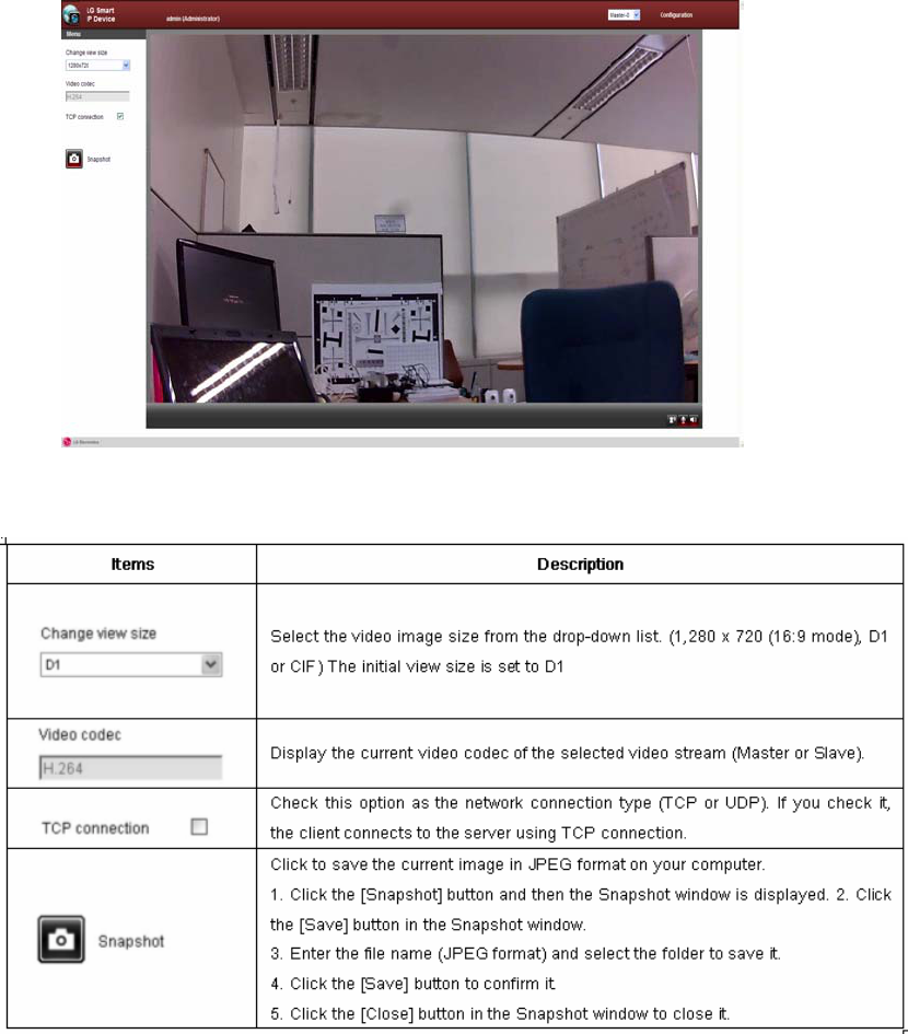
Once the connections are made you need to install the LG client program to
the PC from which you want to access the device. The LG Smart Web Viewer
program is automatically installed when you connect the LG IP device. The LG
Smart Station and the LG Smart Web Viewer program are the network
programs of the LG Video Server and the LG IP cameras.
To view streaming video in Internet Explorer, set your browser to allow ActiveX
controls. If you find this message “This website wants to install the following
add-on: ‘IPCam_Streamer.cab’ from ‘LG ELECTRONICS INC’”, Click the yellow bar
and install LG Smart Web Viewer Program on your computer.
The Layouts and the Live view pages may differ with different OS (Operating
Systems) and Web Browsers.
Care needs to be taken not to run any other applications when the Client Program is
running as it may cause memory shortage.

19
Operation and settings
Recommended PC Requirements Accessing the LG IP device
The LG IP device can be used with most standard operating systems. You can access
the LG IP device by following the below systems and browsers.
Steps:
1. Install LG Smart Station Program
2. Discover LG IP device using the IP Utility
The IP Utility can automatically discover and display LG IP devices on your
network. The IP Utility shows the MAC address, IP address, Model name and so
on.
Note:
The computer running the IP Utility must be on the same network segment
(physical subnet) as the LG IP device.
2.1 Run the IP Utility program.
2.2 Click the [Search] icon or select the [Search] option in the Device search menu.
After a few seconds the found LG IP devices will be displayed in the IP Utility
window.
3. Logging in to the LG Smart Web Viewer
The LG Smart Web Viewer can be used with most web browsers. The
recommended browser is Internet Explorer with Windows.
3.1 Run the IP Utility and find the LG IP devices.
3.2 When the LG IP devices appear in the IP Utility window, double-click IP
address or right click on the same IP address and select "Connect to Web
Page" to start the LG Smart Web Viewer. When accessing the LG Smart Web
Viewer, the authentication dialog appears on the screen.
3.3 Enter the user name and password. (Note that the default administrator user
name and password are “admin”.)
3.4 Click the [OK] button and then the LG Smart Web Viewer is displayed in your
browser.
Items Requirements
Operating System Windows XP Professional, Windows VISTA, Windows 7
CPU Intel Core2 Quard Q6700 (2.66 GHz) or above
Web Browser Microsoft Internet Explorer above the version 6.0 and below the
version 8.0.
DirectX DirectX 9.0 or above
Memory 2 GB or above RAM
Graphics Card 256 MB or above Video RAM
Resolution 1 280 x 720 (with 32 bit color) or higher
20
Notes:
• You can also access the LG Smart Web Viewer as shown below.
3.1 Start your Web browser.
3.2 Enter the IP address of the LG IP device in the address bar of the browse.
3.3. Enter the user name and password set by the administrator.
3.4 Click the [OK] button and then the LG Smart Web Viewer is displayed in
your browser.
The LG Smart Web Viewer needs more time to display it according to the
network conditions.
If the login window is not displayed, check the pop-up blocker. If you set the
pop-up blocker, the login window is not displayed. You must allow the pop-ups.
If you connect the LG Smart Web Viewer for the first time, the Security Warning
window is displayed to install the LG Smart Web Viewer program. You must
install the LG Smart Web Viewer program for using the LG IP device.
If your computer or network is protected by a proxy or firewall, the proxy or
firewall settings can prevent the LG Smart Web Viewer program. Change the
proxy or firewall settings to activate the LG Smart Web Viewer program.
21
Operation and settings
22
Operation and settings

23
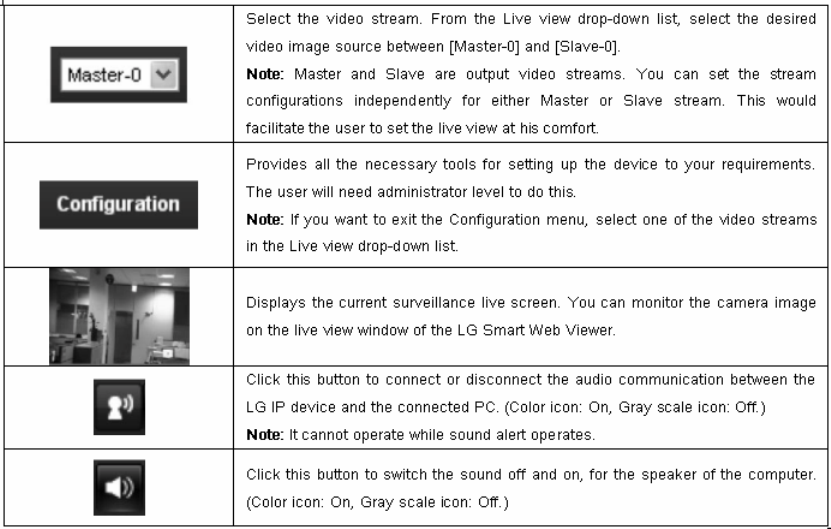
Configuring the LG Network Camera Device
The features and options of the LG IP camera are configured through the
Configuration menu. Only administrator-level users have permission to access the
Configuration menu.
Accessing the Configuration menu
Click the [Configuration] button to display the LG Smart Web Viewer configuration
window.
Warning
The Configuration setup should be made by qualified service personnel or system
installers.
Configuration menu overview
The following table shows the list of menu items.
Main menu Sub menu
Version
Date & Time
Maintenance
Log & Report
System
Language
Camera
Stream
Audio
Audio & Video
Motion detect
Basic
RTP stream
TCP/IP
DDNS
IP filtering
Network
Wireless
User Basic
SD card Basic
Event schedule
Event server
Event
Sensor & Relay
24
Operation and settings
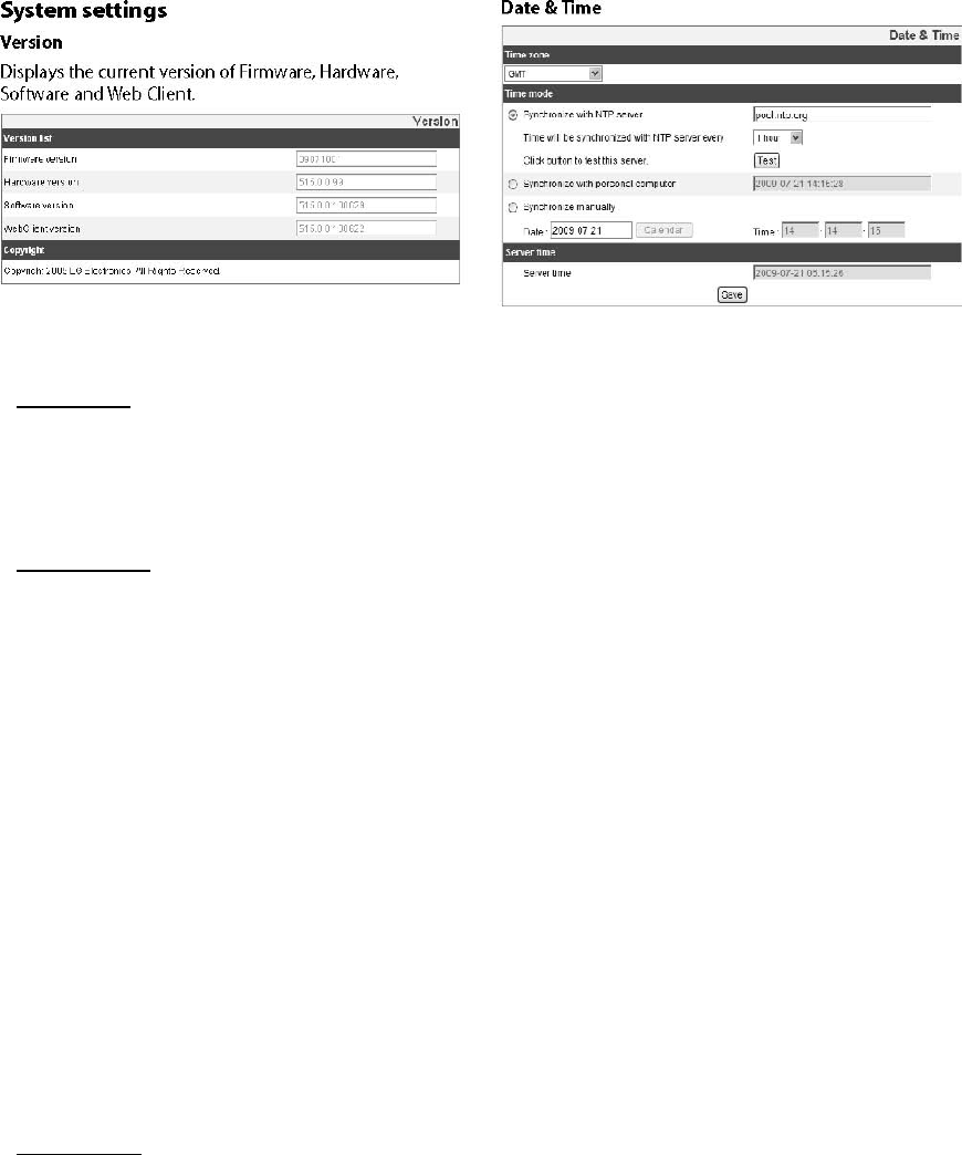
Time zone
Set the time difference from GMT in the area where the IP device is installed.
Select the time zone in the area where the IP device is installed from the drop down
list.
Time mode
> Synchronize with NTP Server: Select if you want to synchronize the IP device’s
date and time with those of the time server called NTP (Network Time Protocol).
Specify the NTP server’s name. Click the [Test] button for connection test to the
server.
> Synchronize with personal computer: Select if you want to synchronize the IP
device’s date and time with your computer.
> Synchronize manually: Select if you want to set the IP device’s date and time
manually. Select the year, month and date by clicking the calendar button. Set hour,
minutes and seconds in the edit boxes.
Notes:
• When system reboot after time setting, time of system could be delayed. If you set
the time correctly, set the [Synchronize with NTP server] option.
• Refer to NTP configuration as operation system of the Recording Server when the
Recording Server use recording function and NTP server.
Server time
> Server time: Displays the current date and time of the IP device.
• Save: Click this button to confirm the settings.
25
Operation and settings
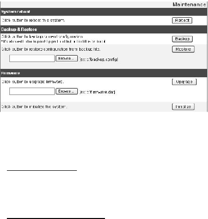
Maintenance
System reboot
Click the [Reboot] button to restart the IP device. It takes some minutes for the IP
device to start again.
Backup and Restore
> Backup: To take a backup all of the settings. If necessary, it make possible to
return to a backup configuration. Click this button and follow the instructions on the
browser to specify the folder and save the setting data of the IP device. This
configuration backup can be restored whenever needed.
> Restore:
1 Click the [Browse] button.
2 Find and open the file in which the configuration setting data is stored.
3 Click the [Restore] button and the system settings will be restored and reboot the
system.
Notes:
• Backup and Restore can happen on IP device having the same version of
firmware. This feature is not intended for multi-configurations or for firmware
upgrades.
• The [Backup] function is allowed in HTTP protocol but not in HTTPS protocol.

26
Operation and settings
Firmware
> Upgrade
1 Click the [Browse] button.
2 Find and open the firmware file.
3 Click the [Upgrade] button to update the firmware.
Note:
When you upgrade the system, it may take some minutes to be done. Do not close
the browser while the upgrade is in progress. If you close the browser, it may cause
a malfunction. You should wait until the confirmation window is displayed. When the
upgrade is finished, the confirmation window will be displayed.
> Initialize: The [Initialize] button should be used with caution. Clicking it will return
all of the IP device’s settings to the factory default values. (Except for Network
settings, PTZ Protocol and Preset settings.)
Log & Report
Log & Report status
The System log provides a summary of the status of the IP device. The unit records
the data of the software activity in a file.
> View Log: Click this button to display the system log information.
> View report: Click this button to display the report of the system.
Language
Language list
Select a language for the LG Smart Web Viewer configuration menu and information
display.
• Save: Click this button to confirm the settings.
27
Operation and settings
Audio & Video settings
Camera
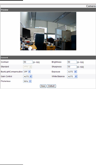
Preview
You can preview the camera image on the preview window.
Operation and settings
General
> Contrast: Edit the contrast value from 0 to 100. Selecting 100 provides the
image with the highest contrast.
> Brightness: Edit the brightness of the camera. It is brighter when a large value is
selected and it is darker when a small value is selected.
> Standard: Displays the video standard of the camera.
> Sharpness: Edit the sharpness value from 0 to 100.
> BackLightCompensation: On or Off BackLightCompensation.
> Exposure: Edit Exposure value.
> Gain Control: Edit Gain control value. (Auto, x1, x2, x4, x8)
> White Balance: Edit White balance value. (Auto, Indoor1, Indoor2)
> Flickerless: Edit Flickerless value. (OFF, 60Hz, 50Hz)
• Save: Click this button to confirm the settings.
• Default: If you want to set the General setting to the default value, click the
[Default] button and then click the [Save] button to confirm it.
28
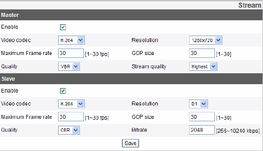
Stream
> Enable: Click to activate the stream function.
> Video codec: Select the video mode (Codec) from the drop-down list. The viewer
can choose between MJPEG and H.264.
> Resolution: Select the image size to be sent from the camera. (1280 x 720 (16:9
mode), D1 (704 x 480), CIF (352 x 240)).
> Maximum frame rate: Set the frame rate of the image.
> GOP size: It means “Group of Pictures”. The higher the GOP, the better is the
video quality of the camera. Edit the value of GOP from 1 to 30. This setting is
valid for H.264 video format only.
> Quality: Select the Quality.
- VBR: The bit rate may vary depending on the complexity of the video to meet the
selected quality.
- CBR: The video quality may vary in order to preserve a constant bit rate.
> Stream quality: If the [Quality] option set to VBR, this option is displayed. Select
the stream quality from the drop down box, the camera supports five types
(Highest, High, Medium, Low and Lowest)
> Bit rate: If the [Quality] option set to CBR, this option is displayed. Edit the bit rate
value from 256kbps to 10240kbps.
Note:
If the ‘Bit rate’ is configured too low with high resolution, the actual frame rate will
decrease because of narrow bandwidth. So you need to set or change the ‘Bit rate’
to high value.
• Save: Click this button to confirm the settings.
29
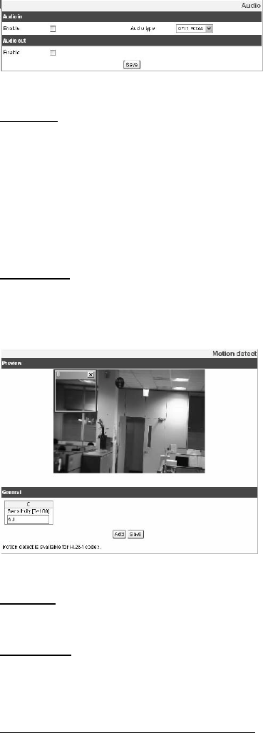
Audio
Audio In
> Enable: Click the check box if you want to send the audio from the microphone
input connector.
Note: The Clients connected to the IP device remain unaffected with additional
changes made in the setting.
> Audio type: Select the codec when you send the audio from the microphone input
connector.
Audio Out
> Enable: Click the check box to output the audio from the speaker.
• Save: Click this button to confirm the settings.
Preview
You can preview the motion detection window on the preview window.
General
> Sensitivity: Enter the sensitivity to detect an object in motion.
> Save: Click this button to confirm the settings.
How to set the motion detect window
1 Click the [Add] button. The motion detect window is displayed. You can add the
five windows maximum for motion detection area.
2 Set the [Sensitivity] option.
3 Click the edge or corner of the window box to adjust the window size for motion
detection.
4 Click the [Save] button to save the settings.
Notes: You can reset the window size. Click one of the window edge or corner and
drag & drop to reset the motion detection area.
30
Motion Detection can be activated when at least one of channels (Master/Slave) is
enabled, Video codec is set to H.264 and GOP size is more than 2.
Network settings
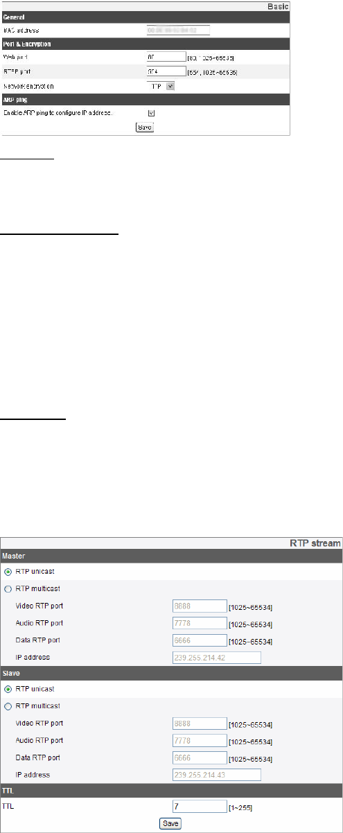
Basic
General
> MAC address: Displays the MAC address.
Port & Encryption
> Web port: The default HTTP port number (80) can be changed to any port within
the range 1,025 to 65,535.
> RTSP port: Check RTSP port. The default port is 554. Other ports can be selected
within the range 1,025 to 65,535.
> Network encryption: Select the HTTP or HTTPS option for security.
Note: The RTSP port number should not be same with the web port number.
ARP Ping
> Enable ARP Ping to configure IP address: Check to enable ARP ping.
• Save: Click this button to confirm the settings
RTP stream
31
RTP (Real-time Transport Protocol) is an internet protocol that allows programs to
manage the real-time transmission of multimedia data, via unicast or multicast.
> RTP unicast: When enabled, the transmission of the data to the specified
equipment happens on a network specifying a single address.
> RTP multicast: When enabled, it reduces the transmission load on the camera by
making the computer of the same segment network receive the same
transmission data. When multicast option is checked then selects Video Port
number, Audio Port number and Data port number.
- Video RTP port: Specify the video transmission port number used for the multicast
streaming. It is initially set to 8,888 and you can edit the between 1,025 and
65,534.
- Audio RTP port: Specify the audio port number used for the multicast streaming. It
is initially set to 7,778 and you can edit this between 1,025 and 65,534.
- Data RTP port: Specify the VA data port number used for the multicast streaming.
It is initially set to 6,666 and you can edit this between 1,025 and 65,534.
- IP address: Set the IP address for RTP multicast.
Note: Each stream using multicast needs its own pair of multicast IP address and
port numbers to avoid address conflict.
TTL
> TTL: This option indicates the Time-To-Live of multicast packets. The default
setting is 7, and the allowed TTL range is from 1 to 255.
• Save: Click this button to confirm the settings.
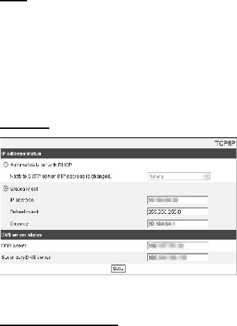
TCP/IP
IP address status
> Automatically set with DHCP: Select this option when a DHCP server is installed
on the network to allow IP address assignment.
- Notify to SMTP server, if IP address is changed: If you select this option, the user
get a notification mail telling about changing of IP of the device.
Note: You should register the SMTP server on the Event server setting to set this
function.
> Statically Set: Select this option when you set a fixed IP address, with this setting
specify the IP address, Subnet mask and default gateway manually.
- IP address: Enter an IP address.
32
- Subnet mask: Enter a subnet mask address.
- Gateway: Enter the gateway address.
DNS server status
> Primary DNS server: Enter the Primary domain name server that translates the
hostnames into IP address.
> Secondary DNS server: Enter the Secondary DNS server address that backups
the Primary DNS.
• Save: Click this button to confirm the settings. DDNS
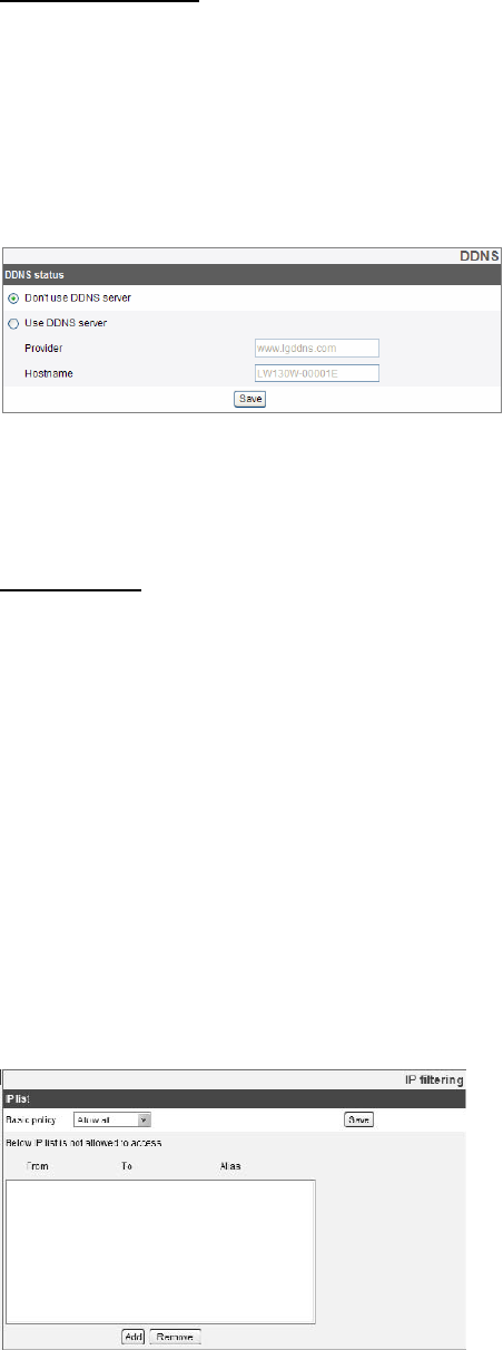
DDNS
This free service is very useful when combined with the LG DDNS Server. It allows
the user to connect the IP device using the URL, rather than an IP Address. This
also solves the problem of having a dynamic IP address.
DDNS status
> Don’t use DDNS server: Disable the DDNS function.
> Use DDNS server: Enable the DDNS function. -Provider: Displays the DDNS
provider.
-Hostname: Enter the hostname you want to use.
• Save: Click this button to confirm the settings.
IP filtering
The access of the IP addresses in the list are allowed or denied according to the
choice made in the drop-down list of the Basic policy option. The administrator can
add up to 10 IP address entries to the list (a single entry can contain multiple IP
addresses). The users from these IP addresses need to be specified in the user list
with the appropriate access rights. The IP list is to control the access permission of
clients by checking the client IP address.
33
IP list
> Basic policy: Select the basic policy type.
- Allow all: Allow all the IP address basically, but the IP addresses in the list are
denied.
-Deny all: Deny all the IP address basically, but the IP addresses in the list are
allowed. It needs at least one IP address to activate this function.
Save: Click this button to confirm the settings.
• Add: Click this button to add the IP address.
1. Click the [Add] button.
2. Set the IP options.
-Alias: Enter the alias.
-From: Enter the start IP address for the IP filtering.
-To: Enter the end IP address for the IP filtering.
Note: If you want to deny or to allow a range of IP addresses, enter the start IP
address to "From" and the end IP address to "To". You can also add an IP address
by entering the same IP address to "From" and "To".
3. Click the [Save] button.
4. Repeat the steps 1 to 3 to add additional IP address.
Remove: Click this button to delete the IP address.
1 Select the alias from the list.
2 Click the [Remove] button. The IP address will be deleted.
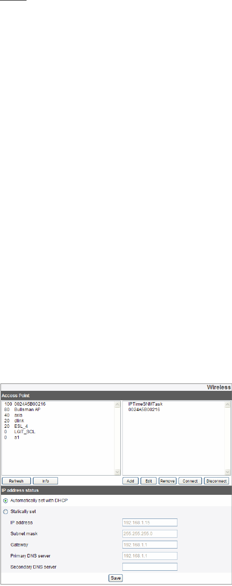
Wireless

34
Access Point
> Click [Refresh] button, display Access Points around. Left number describes signal
strength of access point and Right describes name of access point.
> Click [Info] button, show the detailed information of access point.
> Click [Add Config] button, add access point to right window.
> Click added access point of right window and [Connect] button, Wi-Fi starts
connecting with selected AP. When connecting with AP, connection status is
displayed and cha nged. (Connection status : connecting, IP assigning,
connected, wps connected)
> Click [Disconnect] button, Wi-Fi is disconnected with AP.
Note: The camera user cannot edit, remove, and connect connected AP.
> Click [Add] Button, add access point.
> Click [Edit] Button, edit access point information.
> Click [delete] Button, delete access point.
IP address status
> Automatically set with DHCP: Select this option when a DHCP server is installed
on the network to allow IP address assignment.
> Statically Set: Select this option when you set a fixed IP address, with this setting
specify the IP address, Subnet mask and default gateway manually.
- IP address: Enter an IP address.
- Subnet mask: Enter a subnet mask address.
- Gateway: Enter the gateway address.
- Primary DNS server: Enter the Primary domain name server that translates the
hostnames into IP address.
- Secondary DNS server: Enter the Secondary DNS server address that backups the
Primary DNS.
• Save: Click this button to confirm the settings.
35
User settings
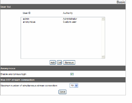
Basic
The IP device is shipped with the login rights of administrator only. If others need
to access the IP device excluding the configuration a login with viewer rights need to
be created. A maximum of 50 users can be created.
User list
> Add the User
You can register a new user with various access rights.
1. Click the [Add] button. User setting dialog is displayed.
2. Enter the new User ID and Password. (Should have a minimum of 4 characters
and preferably a combination of alphanumeric).
3. To confirm the password, retype the password that you typed in the Password box.
4. Select the authority from the drop down list to provide the access rights to each
user and then click the [Save] to confirm your selection.
- Administrator: Allows you to operate setup menus and to view live images.
- Power user: Use of the limited functions of the system (The Configuration menu is
not allowed). A power user can use the Live View and audio functions.
- Normal user: Provides the lowest level of access, Allows to view live images only.
- Custom user: The user can login and view the live stream image only when the
“Enable anonymous login” option is checked to enable it.
Note: Remember the password.
> Edit the registered user
You can change the password or authority.
1. Choose the user ID and then click the [Edit] button.
2. Change the Password or Authority, then click the [Save] button to confirm your
selection.
> Delete the registered user
1. Choose the user ID you want to delete.
2. Click the [Remove] button.
36
Note:
The default administrator user ID ‘admin’ is permanent and cannot be deleted.
Anonymous
> Enable anonymous login Check the box to enable anonymous user login - allows
the user access for only viewing the live stream image.
Maximum RTP stream connection
> Maximum number of simultaneous stream connection: Set this number to limit the
number of simultaneous stream connections. The connections depend on the
stream configuration as shown in the following Maximum RTP stream connection
by stream configuration.
Video
Codec
Resoul
tion
Frame
Rate Quality Maximum
RTP stream
H.264 720p 30 HIGHEST Up to 4
MJPEG 720p 20 HIGHEST Up to 4
Note: Preview window of the IP device setting is affected by this setting. • Save:
Click this button to confirm the settings.
SD Card settings
Basic

37
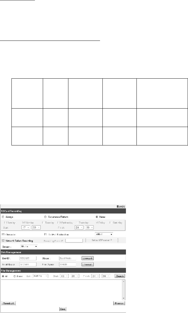
SD Card Recording
> Always: Start the recording at once.
> Recurrence Pattern: The recording is started according to the setting time of the
selected day.
Note: You cannot set the time for a day. It will start the recording for the selected day
of the time.
> Never: [Always] and [Recurrence Pattern] recording functions are not activated.
> Overwrite: If the micro SD card has insufficient space and this option will be
activated. It will overwrite the oldest data.
> DiskFull Notification: Sends a warning e-mail to the SMTP server when the micro
SD card has fully recorded. Select the SMTP server from the drop-down list. You
should register the SMTP server on the Event server setting to set this function.
> Network Failure Recording: Select the checkbox to activate the micro SD card
recording function. If the system does not work with recording server, the system
will record the data to the micro SD Card. When the system connects to the
recording server again, the recorded data of the micro SD card will transfer to the
recording server automatically.
> Recording Server IP: Enter the recording server IP
> Set as NTP server IP: Click this button to use the entered Recording Server IP as
the NTP server IP
> Stream: Select the stream type for the recording.
Notes:
The recorded file name is made automatically as the “[Created date of the
file]_[GMT Recording Time]+(-)[Value of the Local Time minus GMT Time
(Second)]_[Use or not of the Daylight saving time(N/D)]
Disk Management
> Using the micro SD card
1 Insert the micro SD card carefully to the micro SD card slot of the camera.
2 Click the [Mount] button. If the micro SD card is mounted to the system correctly,
the [Mount] button will be changed to the [Unmount] button.
3 Displays the information of the [Disk ID], [Status], [Total Space] and [Free Space]
options.
Notes:
When the micro SD card is mounted, you should format the micro SD card. After the
micro SD card format is finished, you should click the [Mount] button to use it.
When you use the micro SD card format function, it may not progress immediately.
In this case, you should try it again after waiting a few minutes.
> Remove the micro SD card
1 Click the [Unmount] button. If the micro SD card is unmounted from the system
correctly, the [Unmount] button will be changed to the [Mount] button.
2 Remove the micro SD card from the micro SD card slot of the camera.

38
Note: When you use the Unmount function, it may not progress immediately.
Operations such as recording of the system and reading of data are required stop
time before the Unmount function is activated. You should try it again after waiting a
few minutes.
File Management
Display the recorded file of the micro SD card on the list.
Click the [Search] button to display the recorded file. The list will be updated when
you click the [Search] button.
> To view the recorded file of the micro SD card
1. Select the search option.
-All: Search the all recorded files in the micro SD card.
-Some: You can set the search condition by using the date and time options.
2. Click the [Search] button and then the search result is displayed on the list.
> Download: You can download the recorded data of the list to your PC. Select a
recorded file on the list and click the [Download] button. The two confirmation
window is displayed. You should download the all files that the recorded file(*.DAT)
and information file(*.INFO).
39
Notes: It is recommended to deactivate the [Overwrite] function before you
download the file. When [Overwrite] function is activated, the downloading file might
be overwritten, if the micro SD card has insufficient space. The downloaded file
can be played by using the LG Smart Station player.
> Remove: Delete file from the SD card.
• Save: Click this button to confirm the settings.
Event settings
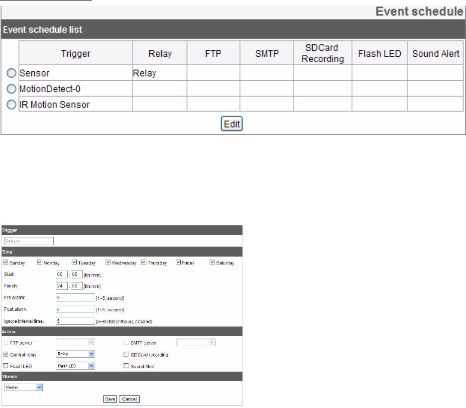
Event schedule
When an event (VA/Motion detect/Sensor event) occurs, this unit records the live
images and routes as configured.
Event schedule list
>To edit the Event Schedule
1. Select the Trigger event and click the [Edit] button. Event schedule window is
displayed.
2. Set the options.
40
Trigger: Displays the selected trigger event.
Time: Sets the Day, Start, Finish, Pre alarm, Post alarm and Ignore interval time
options.
Action: Selects the options. This occurs when the event runs.
-FTP server/SMTP server: Uploading of images to an FTP server, or e-mail
notification.
-Control relay: The relay is activated or deactivated.
-SDCard recording: Record on the SD card when the event runs.
-Flash LED: Flash on when the event runs.
-Sound Alert: Sound Alert on when the event runs.
• Stream: Selects the stream of the connected camera.
3. Click the [Save] button to confirm the settings.
Notes:
You should register the SMTP and FTP server on the Event server setting to set this
function.
Recording of event (VA/Motion detect/ Sensor event) runs every 5 minutes split file.
If the capacity of the SD card remains less than 200 MB, stop recording or overwrite
new file after delete old one as [Overwrite] setting. The overwritten file cannot play or
may malfunction when you download. Recorded file on the SD card, is recording 1
frame per second when set video codec to MJPEG.
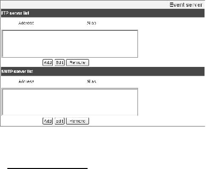
Event Server
FTP server list
Event Servers are used to receive the recorded video clip.
> To add the FTP server
1 Click the [Add] button. FTP server setting window is displayed.
2 Set the FTP server options.
- Alias: Type the FTP Server name to upload the image files.
- Address: Enter the FTP server’s IP address.

41
- Port: Enter the port number. The default FTP port is 21.
- User ID: Type the user name for the Folder shared in the FTP server.
- Password: Type the password for the folder shared in the FTP Server.
- Folder: Type the path with the folder that is shared in the FTP server.
-Test: Click [Test] button to test the FTP server.
3. Click the [Save] button to confirm the settings.
> To edit the FTP server
1 Choose the FTP server in the FTP server list.
2 Click the [Edit] button. You can check or edit the FTP server options.
> To delete the FTP server
1 Choose the FTP server in the FTP server list.
2 Click the [Remove] button. This would remove the FTP server from the list.
SMTP server list
By selecting the e-mail option, a still image of the event is captured and an e-mail
with the attached image file is sent to the specified mail address.
> To add the SMTP server
1 Click the [Add] button. SMTP server setting window is displayed.
2. Set the SMTP server options.
- Alias: Enter the SMTP server name.
- User ID: Enter the user ID of the SMTP server. This would be the one who owns
the mail account.
- Password: Enter the password of the SMTP server.
- Address: Enter the SMTP server address.
- Port: Enter the port number. The default port is 25.
- Enable SSL: Check when use the SSL (Secure Socket Layer) protocol. SSL
protocol is cryptographic protocols that provide secure communication on a network.
42
- Receiving address: Type the recipients e-mail address. You can specify only one
recipient e-mail address.
- Administrator address: Type the e-mail address of the administrator.
- Subject: Enter the subject/title of the e-mail. - Message: This message can
describe the information of the acquired IP address, etc.
- Test: Click [Test] button to test the SMTP server.
3. Click the [Save] button to confirm the settings.
> To edit the SMTP server
1 Choose the SMTP server in the SMTP server list.
2 Click the [Edit] button. You can check or edit the SMTP server options.
> To delete the SMTP server
1 Choose the SMTP server in the SMTP server list.
2 Click the [Remove] button.
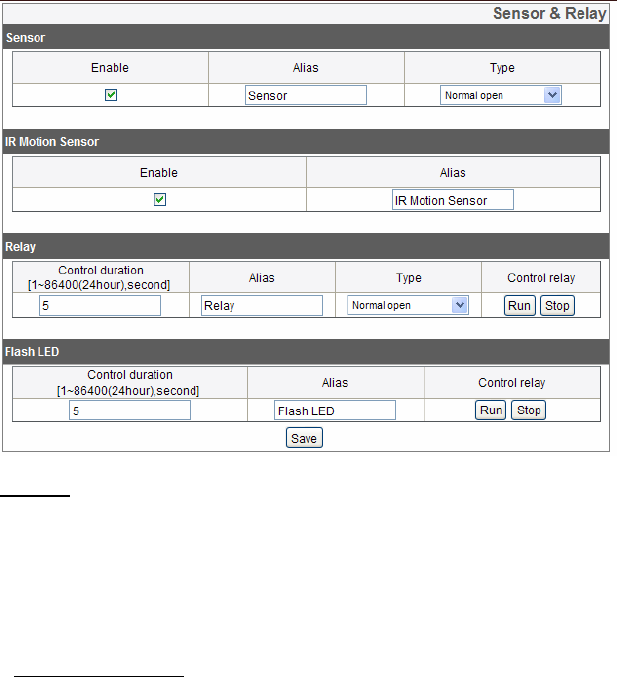
Sensor & Relay
Sensor
> Enable: Mark up when you want to activate the sensor.
> Alias: Display the sensor name.
> Type: Select the sensor type.
IR Motion Sensor
> Enable: Mark up when you want to activate the IR motion sensor.
> Alias: Display the IR motion sensor name.

43
Relay
> Control duration: Enter the relay time.
> lias: Display the relay name.
> Type: Select the relay type.
> Control relay:
- Run: Click to activate the relay.
- Stop: Click to stop the relay.
Flash LED
> Control duration: Enter the Flash LED running time.
> Alias: Display the FLASH LED name.
> Control relay:
- Run: Click to activate the Flash LED.
- Stop: Click to stop the Flash LED.
• Save: Click this button to confirm the settings.

44
Troubleshooting
This section provides useful information to help you to resolve any difficulty you
might have with your LG IP device. Fault symptoms, possible causes and remedial
actions are provided here.
IP Setting problems
• ARP/Ping: Disconnect and reconnect the power to the network camera. The
device should get the IP within 2 minutes.
• Ping your camera: Open the command prompt on your computer, type ping with
the IP address of the network device. The reply obtained by this command provides
explanation for the cause of the problem.
bytes = 32 time = 2 ms indicates that the IP address is already used and cannot
reuse the same. A new IP address needs to be obtained.
Destination host unreachable: indicates that the network device and your computer
do not fall in the same subnet hence needs to get a new IP address. Contact the
system administrator for the required help.
Request timed out: Indicates that the IP is free as it is not used by anyone and the
network device can obtain this.
• IP Conflicts: If the LG network device is set with a static IP address and if the
DHCP option is set then there may be IP’s same as the network device and other
network partner. Hence set the static IP address to 0.0.0.0 to resolve this conflict.
Cannot access the camera from browser:
Reconnect the network camera with power and check the ping operation to know if
the IP is used by others.
Disable the proxy setting in the Browser if you are using a proxy server.
Check for proper cabling and network connections, try to ping after verifying the
connectivity.
Sometimes when HTTPS is enabled, we would be checking the URL with http, in
this case manually change the URL to the http/https accordingly.
Verify the DNS and Gateway settings if the IP address is assigned statically to the
network device.

45
Troubleshooting
Accessing camera external to the local network
Firewall Protection: Check for the internet firewall with the system administrator,
either he has to do port forwarding or modify the DMZ function on the router.
Default router needed: Check if you need configure the router settings.
Sporadic network performance
Network Switches or hubs used may be of the lower configuration and the load on
this may not meet the required conditions of our network camera. Check for the
RJ-45 cables that are used for the network connectivity.
Login Password lost
Reset the camera by pressing the Factory Reset button for more than 10 seconds to
restore default settings. After do the factory reset, login using the default username
and password.
Video Streaming problems
If the video streaming does not start on the Web browser, install the LG Web Client
ActiveX program on your computer following the instructions on the Web browser.
When Windows IE browsers are used always take care to allow pop ups, check this
option before we run the web client.
Check the quality of image by referring the video settings as described in the manual.
Sometimes there would be intermittent or very slow video streaming, this may be
because of the higher resolution and frame rate that are set for the video. The
video streaming may appear poor at times; this may be because of the network
traffic, too many devices connected to the switch or hub, enabling motion detection
to each of the video streams and because of other programs running on your
computer.
If the images appear to be blurred adjust the focus of the network camera to get a
clear image.

46
Troubleshooting
Video images if appear white and black adjust the camera settings in the
Audio&Video to get back the colorful image.
Select the Night mode if the network camera is connected at a place where
surrounding light is less or dark.
If we obtain lower frame rate than set we need to check from the system
administrator for sufficient bandwidth available or reduce the number of applications
running on the client computer.
If the client PC’s are unable to access the multicast stream, check with the system
administrator for the use of a valid multicast address or check if the router is
supporting multicasting.
If the images appear to have white of gray stripes on it, upgrade the Video graphics
driver on the client PC to the latest version.
Video images may be noisy if you are using the camera in a very low light
environment or the bit rate/ quality is set to very low values. Provide higher values
for quality and support the surrounding environment with enough light.
Audio condition
The client computer that is interacting with the camera needs to have a sound card
that is functional to support speaker and microphone.
The sound card needs to be checked for its support for full duplex communication.
Ensure that the mute button of the client computer is not set and all the audio
settings are correct.
Speaker button on the web viewer should be enabled to listen the audio from the
network camera.
Ensure that the bidirectional audio button is enabled on the Web viewer and the
microphone is set.
Change the input and the output gain for microphone and the speaker respectively
to set correct audio level.
For all further support please contact the supplier or forums or websites.
47
Open source software notice
The following GPL executables and LGPL libraries used in this product are subject
to the GPL2.0/LGPL2.1 License Agreements:
GPL EXECUTABLES:
Linux kernel 2.6, bash, busybox, gdbm, libreadline, moduleinit-tools, mount,
mtd-utils, net-tools, quftp, tar, util-linux
LGPL LIBRARIES:
Glibc, libelf, libesmtp, live.media
LG Electronics offers to provide source code to you on CD-ROM for a charge
covering the cost of performing such distribution, such as the cost of media, shipping
and handling upon e-mail request to LG Electronics at: opensource@lge.com
This offer is valid for a period of three (3) years from the date of the distribution of
this product by LG Electronics.
You can obtain a copy of the GPL, LGPL licenses from http://
www.gnu.org/licenses/old-licenses/gpl-2.0.html and http://
www.gnu.org/licenses/old-licenses/lgpl-2.1.html.
This product includes mDNSResponder component which is licensed under the
terms of the Apache License, Version 2.0.
You can obtain a copy of the Apache license from http://
www.apache.org/licenses/LICENSE-2.0.html.

48
Open source software notice
This product includes
• dhcp client :
Copyright © 2004-2008 by Internet Systems
Consortium, Inc. (“ISC”) Copyright ©
1995-2003 by Internet Software Consortium
expat library : Copyright © 2006 expat maintainers. libcap
libjpeg : Independent JPEG Group Copyright © 1991 1998, Thomas G. Lane.
libmd5 : Copyright © 2002 Aladdin Enterprises.
libncurses : Copyright © 1998,2002 Free Software Foundation, Inc.
libpcre : Copyright © 1997-2009 University of Cambridge
libxml2 : Copyright © 1998-2003 Daniel Veillard.
lighttpd : Copyright © 2004, Jan Kneschke,
incremental
ntpdate : Copyright © David L. Mills 1992-2006
OpenSSL :
> cryptographic software written by Eric Young (eay@cryptsoft.com).
> software written by Tim Hudson (tjh@cryptsoft.com).
> software developed by the OpenSSL Project for use in the OpenSSL Toolkit.
(http://www. openssl.org)
PHP software, freely available from http://www.
php.net/software/ : Copyright © 1999 - 2009
The PHP Group.
Speex : > Copyright 2002-2008 Xiph.org Foundation
> Copyright 2002-2008 Jean-Marc Valin
> Copyright 2005-2007 Analog Devices Inc.
> Copyright 2005-2008 Commonwealth Scientific and Industrial Research
Organisation (CSIRO)
> Copyright 1993, 2002, 2006 David Rowe > Copyright 2003 EpicGames
49
Open source software notice
> Copyright 1992-1994 Jutta Degener, Carsten Bormann
• Zlib : Copyright © 1995-2002 Jean-loup Gailly and Mark Adler.
All rights reserved.
Permission is hereby granted, free of charge, to any person obtaining a copy of
this software and associated documentation files (the “Software”), to deal in the
Software without restriction, including without limitation the rights to use, copy,
modify, merge, publish, distribute, sublicense, and/or sell copies of the Software,
and to permit persons to whom the Software is furnished to do so, subject to the
following conditions:
THE SOFTWARE IS PROVIDED “AS IS”, WITHOUT WARRANTY OF ANY KIND,
EXPRESS OR IMPLIED, INCLUDING BUT NOT LIMITED TO THE
WARRANTIES OF MERCHANTABILITY, FITNESS FOR A PARTICULAR
PURPOSE AND NONINFRINGEMENT. IN NO EVENT SHALL THE AUTHORS
OR COPYRIGHT HOLDERS BE LIABLE FOR ANY CLAIM, DAMAGES OR
OTHER LIABILITY, WHETHER IN AN ACTION OF CONTRACT, TORT OR
OTHERWISE, ARISING FROM, OUT OF OR IN CONNECTION WITH THE
SOFTWARE OR THE USE OR OTHER DEALINGS IN THE SOFTWARE.

50
Specification
ITEM LW130W
Image Sensor Progressive Scan CMOS (1.0 Mega Pixels)
Lens M12 Board Lens
Resolution Up to 1280 X 720
Light 1W Flash LED
Camera
Image Enhancement Auto Exposure Control, Auto White Balance, Digital
Zoom(Viewer), Digital Day & Night
Video Out RJ-45 (Network)
Compression H.264, MJPEG
Frame Rate (Max) 30 fps @ 1280 x 720 (16:9 mode)
Video
Multi-Streaming Dual Streaming
Audio In/Out 1/1 (Line level input/output)
Compression G.711, G.726 Support
Audio
2-way Audio Support
Alarm In/Out 1/1
Motion Detection Human Sensing
Event Notification Relay Out, Email, FTP
Event
Pre Event Buffering Support
Ethernet 10/100 Ethernet
Wireless LAN 802.11 b/g/n, WPS support
Security Password Protection, HTTPS(SSL, TLS)
Network
Protocol TCP/IP(IPv4), HTTP, HTTPS, RTP, RTSP, UDP, DHCP, FTP,
SMTP, NTP, ARP, ICMP, DDNS(LG)
Integrated Client LG Smart Station (64 channels recording and monitoring
feature)
Web Client Live monitoring and system management for a device
System Update LG Smart Station or Web Client
Managem
ent
Connections Up to 4
Power Source DC 5 V (±20 %)
Input current DC 5V : Maximum 1000 mA
Operating Temperature -10 ℃ to 50 ℃
Operating Humidity 0 % RH to 80 % RH
Misc.
Dimension (W x H x D) With Stand : 100 X 70 X 130 mm,
Without Stand : 60 X 45 X 100 mm

51