LG Electronics USA 9QK-MB0402C1 Bluetooth Module User Manual
LG Electronics USA Bluetooth Module Users Manual
Users Manual
͑͑͑͑͑͑͑͑͑͑͑͑͑͑͑͑͑͑͑͑͑͑͑͑͑͑͑͑͑͑͑͑͑͑͑͑͑͑͑͑͑͑͑͑͑͑͑͑͑͑͑͑͑͑͑͑͑͑MCSLOGIC
Product Approval Datasheet V1.00 1/19
Copyright ¤
¤
2011 MCS LOGIC Limited. All rights reserved
Confidential
241&7%6#22418#.#5*''6
241&7%6
/%5.QIKE%NCUU$NWGVQQVJ
/QFWNG
/1&'
.0#/'
/$
%
%7561/'4
.)'NGEVTQPKEU
%JGEMGF$[ #RRTQXGF$[ %QORCP[5GCN
MCSLOGIC
͑͑͑͑͑͑͑͑͑͑͑͑͑͑͑͑͑͑͑͑͑͑͑͑͑͑͑͑͑͑͑͑͑͑͑͑͑͑͑͑͑͑͑͑͑͑͑͑͑͑͑͑͑͑͑͑͑͑MCSLOGIC
Product Approval Datasheet V1.00 2/19
Copyright ¤
¤
2011 MCS LOGIC Limited. All rights reserved
Confidential
4GXKUKQP*KUVQT[
8GTUKQP
&CVG
4GXKUKQP&GUETKRVKQP
0.1
0.2
0.3
0.4
0.5
0.6
0.7
0.9
1.0
11/05/27
11/06/03
11/07/08
11/07/15
11/07/21
11/08/17
11/09/20
11/09/28
11/09/29
First release
Changed Pin Description
Changed Label Information
Changed Dimension
Changed BOM
Changed Mechanical Dimension
Derating release
Add PCB Layout
Changed Label Information

͑͑͑͑͑͑͑͑͑͑͑͑͑͑͑͑͑͑͑͑͑͑͑͑͑͑͑͑͑͑͑͑͑͑͑͑͑͑͑͑͑͑͑͑͑͑͑͑͑͑͑͑͑͑͑͑͑͑MCSLOGIC
Product Approval Datasheet V1.00 3/19
Copyright ¤
¤
2011 MCS LOGIC Limited. All rights reserved
Confidential
Table of Contents
1.1GENERAL DESCRIPTION .......................................................................................................................................... 4
1.2QUALITY ........................................................................................................................................................................ 4
1.3TEST ................................................................................................................................................................................ 4
1.4BLOCK DIAGRAM ....................................................................................................................................................... 5
1.5PIN DESCRIPTIONS ..................................................................................................................................................... 6
1.6ELECTRICAL CHARACTERISTICS ......................................................................................................................... 7
1.7RELIABILITY TEST CONDITIONS ........................................................................................................................ 10
1.8MODULE’S LABEL INFORMATION ...................................................................................................................... 11
1.9MECHANICAL DIMENSION .................................................................................................................................... 12
1.10BILL OF MATERIALS ............................................................................................................................................... 14
1.11PACKING INFORMATION ....................................................................................................................................... 15
1.12TRAY ............................................................................................................................................................................. 15
1.13INNER BOX .................................................................................................................................................................. 16
1.14OUTTER BOX .............................................................................................................................................................. 17
1.15PACKAGE RELIABILITY TEST CONDITIONS ................................................................................................... 18
1.16MODULE POSITION GUIDE .................................................................................................................................... 19

͑͑͑͑͑͑͑͑͑͑͑͑͑͑͑͑͑͑͑͑͑͑͑͑͑͑͑͑͑͑͑͑͑͑͑͑͑͑͑͑͑͑͑͑͑͑͑͑͑͑͑͑͑͑͑͑͑͑MCSLOGIC
Product Approval Datasheet V1.00 4/19
Copyright ¤
¤
2011 MCS LOGIC Limited. All rights reserved
Confidential
)GPGTCN&GUETKRVKQP
MB0402C1 is a fully integrated Bluetooth module. It is based on CSR’s Bluecore4-ROM with
specific interface design to meet LG Electronics’s needs.
MB0402C1 is compatible with Bluetooth specification version 2.1. It integrates RF, Baseband
controller, etc., a completed Bluetooth subsystem.
(GCVWTGU
͞ Operation Range (Class II) : 10 meters
͞ Operating Temperature Range : -10ఁ ~ 80ఁ
͞ Operating VDD Range : 3.0 V ~ 3.6V
͞ Interface : UART
͞ Internal Antenna
͞ Fully Compatible with Bluetooth Specification 2.1
͞ RoHS Compliant
#RRNKECVKQPU
͞ Consumer Products
3WCNKV[
Qaulity should meet each condition which mentioned on this specification. However, the items
which are not mentioned on this specification follow the inspection agreements and standards
which are agree with both companies.
6GUV
Electrical characteristics are tested for every products. However, if there are any objection in
judgement, it should be treated with agreements of companies.
͑͑͑͑͑͑͑͑͑͑͑͑͑͑͑͑͑͑͑͑͑͑͑͑͑͑͑͑͑͑͑͑͑͑͑͑͑͑͑͑͑͑͑͑͑͑͑͑͑͑͑͑͑͑͑͑͑͑MCSLOGIC
Product Approval Datasheet V1.00 6/19
Copyright ¤
¤
2011 MCS LOGIC Limited. All rights reserved
Confidential
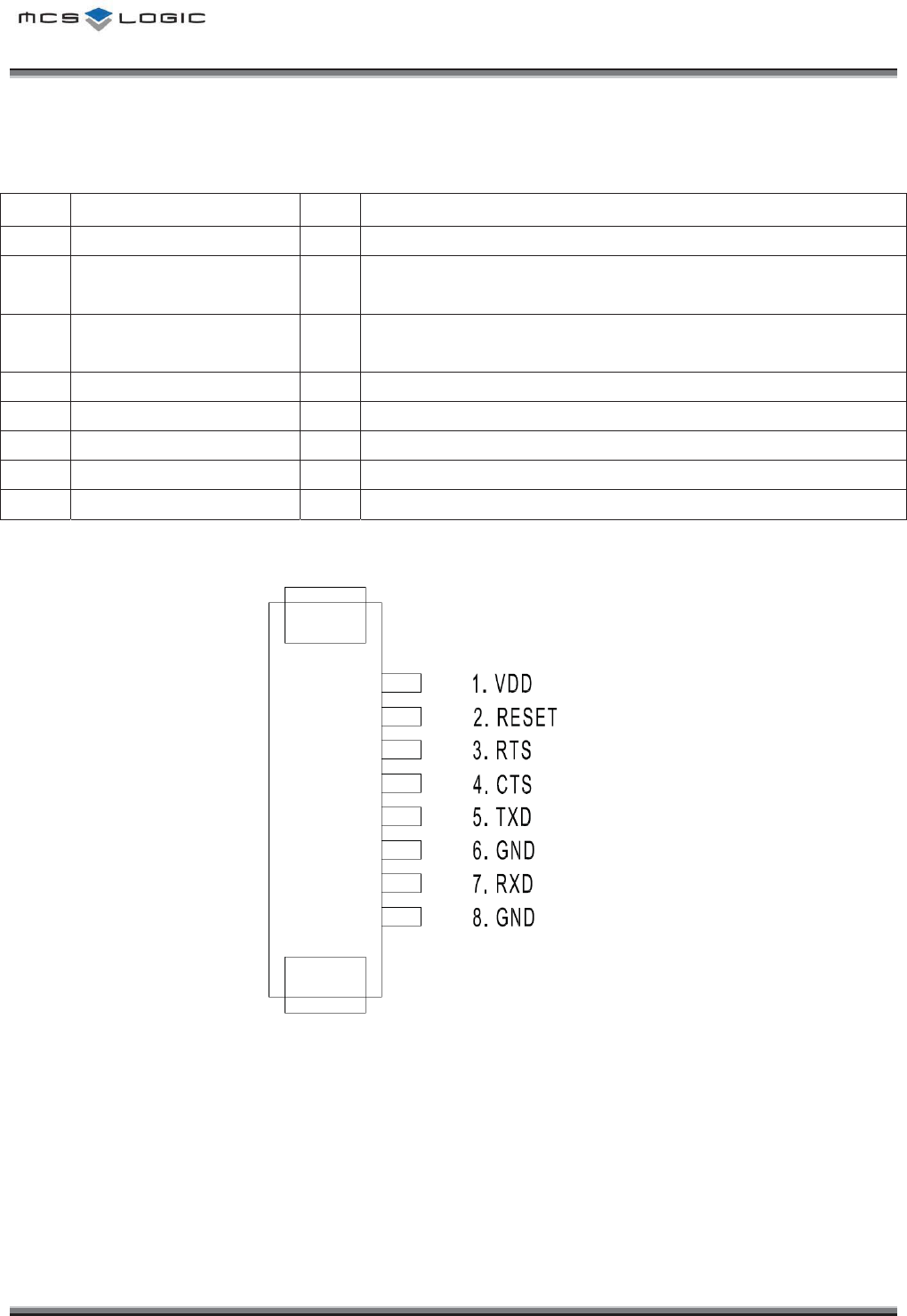
2KP&GUETKRVKQPU
No
Pin Name
I/O
Description
1
VDD
I
Positive Input for the internal regulator (3.0 ~ 3.6V)
2
RESET
I
Reset if low. Input debounced so must be low for >5ms to
cause a reset
3
RTS
O
Bluetooth UART Request to Send.
Active-low request.
4
CTS
I
Bluetooth UART Clear to Send.Active-low clear.
5
TXD
O
Bluetooth UART Serial Output.
6
GND
-
Ground.
7
RXD
I
Bluetooth UART Serial Input.
8
GND
-
Ground
͑͑͑͑͑͑͑͑͑͑͑͑͑͑͑͑͑͑͑͑͑͑͑͑͑͑͑͑͑͑͑͑͑͑͑͑͑͑͑͑͑͑͑͑͑͑͑͑͑͑͑͑͑͑͑͑͑͑MCSLOGIC
Product Approval Datasheet V1.00 7/19
Copyright ¤
¤
2011 MCS LOGIC Limited. All rights reserved
Confidential
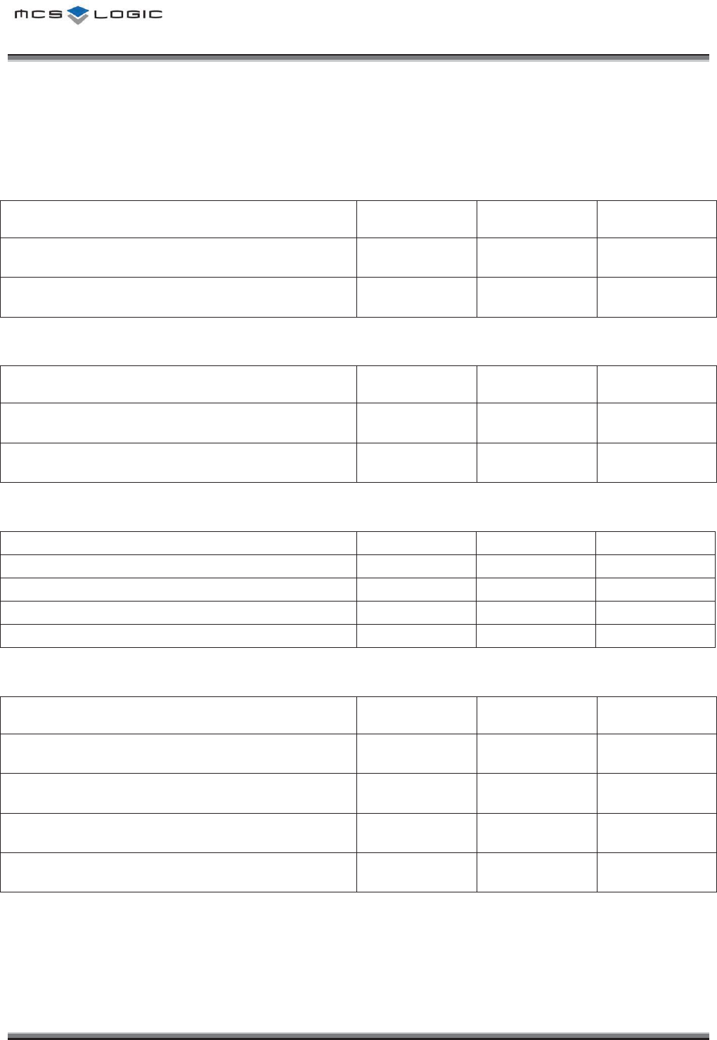
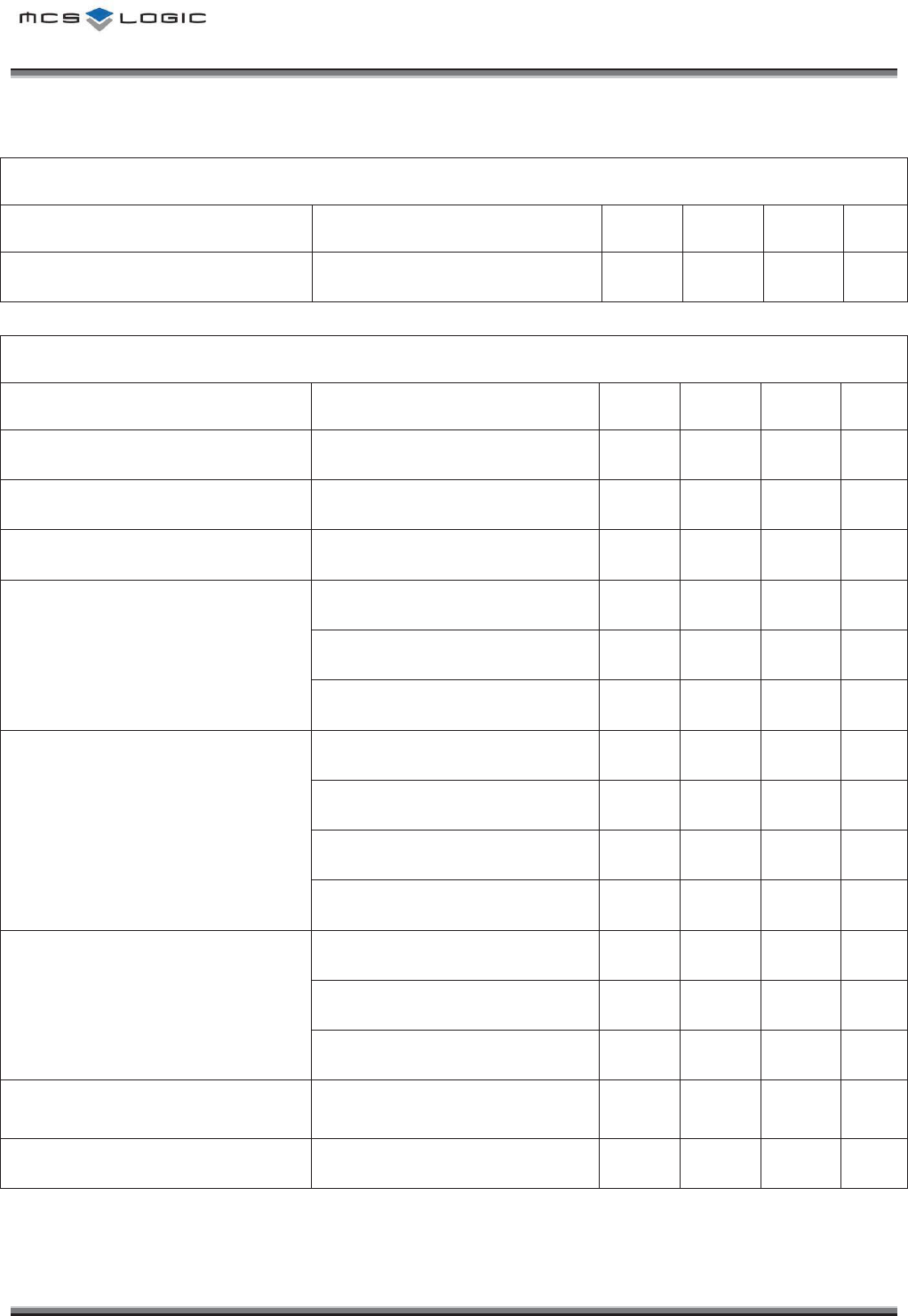
'NGEVTKECN%JCTCEVGTKUVKEU
Conditions : VDD = 3.3V, Ta = 25 ଇ, unless otherwise noted.
Absolute Maximum Ratings
Parameter
Min
Max
Unit
Power Supply Voltage : VDD -0.4V 3.6V DCV
Storage Temperature -40 85 ఁ
Recommended Operating Conditions
Parameter
Min
Max
Unit
Power Supply Voltage 3.0V 3.6V DCV
Operation Temperature -10 80 ఁ
Current consumption
Parameter
Avg
Peak
Unit
Standby
0.3
-
mA
TX-CW
57.6
63
mA
TX-Modulation
36
63
mA
RX
37.9
-
mA
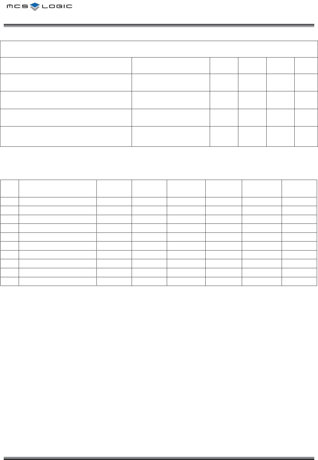
Input/Output Characteristics
Parameter
Min
Max
Unit
VIL Input Voltage Low -0.4 0.8 V
VIH Input Voltage High 0.7*VDD VDD+0.4 V
VOL Output Voltage Low - 0.2 V
VOH Output Voltage High VDD-0.2 - V
͑͑͑͑͑͑͑͑͑͑͑͑͑͑͑͑͑͑͑͑͑͑͑͑͑͑͑͑͑͑͑͑͑͑͑͑͑͑͑͑͑͑͑͑͑͑͑͑͑͑͑͑͑͑͑͑͑͑MCSLOGIC
Product Approval Datasheet V1.00 8/19
Copyright ¤
¤
2011 MCS LOGIC Limited. All rights reserved
Confidential
General Performance
Parameter
Condition
Min
Type
Max
Unit
Frequency Range
2402
2480
MHz
Transmitter Performance
Parameter
Condition
Min
Type
Max
Unit
Transmit Power -6 0 4
dBm
Power density - - 20
dBm
20dB bandwidth
1000
KHz
Adjacent channel power
±2% - - -20
dBm
±3% - - -40
dBm
±4% - - -40
dBm
Out-band Spurious Emission
30MHz ~ 1GHz - - -36
dBm
1GHz ~ 12.75GHz - - -30
dBm
1.8GHz ~ 1.9GHz - - -47
dBm
5.1GHz ~ 5.3GHz - - -47
dBm
Modulation Characteristic
∆F1avg 140
- 175
KHz
∆F2max 115
- -
KHz
∆F2avg / ∆F1avg 80
- - %
Initial Carrier Frequency
Tolerance
DH1 packet -75
- 75
KHz
Carrier Frequency Drift DH5 packet -25
25
KHz
͑͑͑͑͑͑͑͑͑͑͑͑͑͑͑͑͑͑͑͑͑͑͑͑͑͑͑͑͑͑͑͑͑͑͑͑͑͑͑͑͑͑͑͑͑͑͑͑͑͑͑͑͑͑͑͑͑͑MCSLOGIC
Product Approval Datasheet V1.00 9/19
Copyright ¤
¤
2011 MCS LOGIC Limited. All rights reserved
Confidential
Receiver Performance
Parameter
Condition
Min
Type
Max
Unit
Sensitivity at 0.1% BER
Single slot
(DH1 packet)
-70
- -
dBm
Sensitivity at 0.1% BER
Multi slot
(DH5 packet)
-70
- -
dBm
Maximum received signal at 0.1% BER
-20
- -
dBm
Maximum level of intermodulation
interferers
f1-f2 = 5 MHz,
Pwanted= -64 dBm
-39
- -
dBm
Derating
NO
ITEM SIZE VALUE
RATED
V/C/W
INPUT
VOLTAGE
INPUT
CURRENT
USAGE
RATIO
1
CL05F105ZQ5NNNC
1.0 X 0.5
1uF
6.3V
3.3V
-
52.38%
2
CL05B103KB5NNNC
1.0 X 0.5
10nF
50V
3.3V
-
6.60%
3
CL05B104KO5NNNC
1.0 X 0.5
100nF
50V
3.3V
-
6.60%
4
RC1005J222CS
1.0 X 0.5
2.2KΩ
1/16W
3.3V
0.0001%
5
CIH05T15NJ
1.0 X 0.5
15nH
300mA
3.3V
60mA
20%
6
CIH05T10NJ
1.0 X 0.5
10nH
300mA
1.8V
<0.01uA
<0.033%
7
CL05C221FB5NNNC
1.0 X 0.5
220pF
50V
1.8V
3.6%
8
CL05B103KB5NNNC
1.0 X 0.5
10nF
50V
1.8V
3.6%
9
CL05B104KO5NNNC
1.0 X 0.5
100nF
50V
1.8V
3.6%
10
CL05F105ZQ5NNNC
1.0 X 0.5
1uF
6.3V
1.8V
28.57%
͑͑͑͑͑͑͑͑͑͑͑͑͑͑͑͑͑͑͑͑͑͑͑͑͑͑͑͑͑͑͑͑͑͑͑͑͑͑͑͑͑͑͑͑͑͑͑͑͑͑͑͑͑͑͑͑͑͑MCSLOGIC
Product Approval Datasheet V1.00 10/19
Copyright ¤
¤
2011 MCS LOGIC Limited. All rights reserved
Confidential
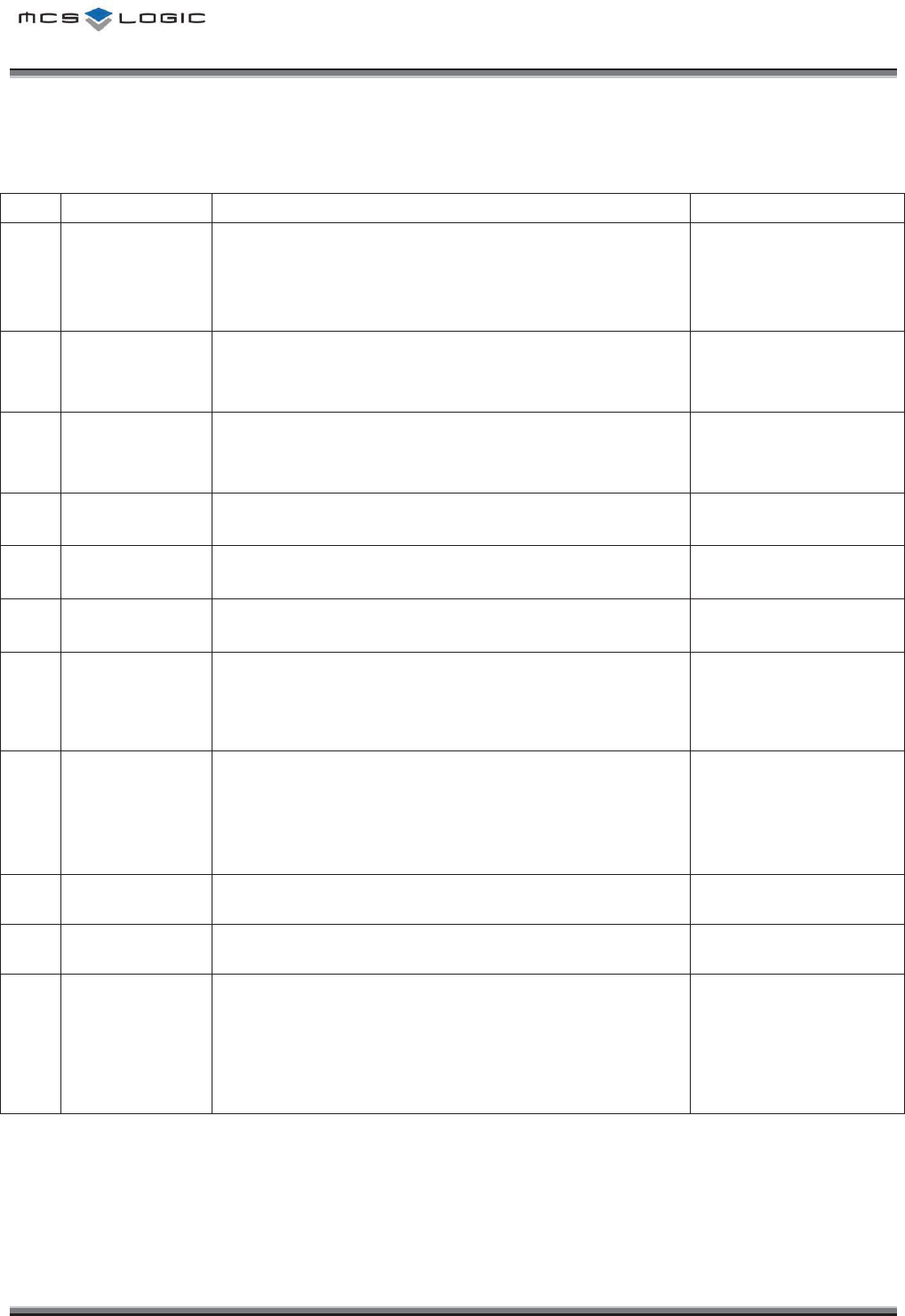
4GNKCDKNKV[6GUV%QPFKVKQPU
NO
ITEM
Condition
Characteristics
1
Constant
Humidity
Load Test
Initial value measured at standard test condition
Test Conditions : 35ఁ, 90% RH, 100hr
25ఁ, 50% RH, 2hr
Supply Voltage Condition : standard ρ5%
No electrical problem
2
High Temp
Load Test
Initial value measured at standard test condition.
Test Conditions : 25ఁ Î 85ఁ, 100hr (Within 1hr)
Supply Voltage Condition : standard ρ5%
No electrical problem
3
Low Temp
Load Test
Initial value measured at standard test condition.
Test Conditions : 25ఁ Î -40ఁ, 100hr (Within 1hr)
Supply Voltage Condition : standard ρ5%
No electrical problem
4
High Temp
Storage Test
Initial value measured at standard test condition.
Test Conditions : 85ఁ, 100hr
No electrical problem
5
Low Temp
Storage Test
Initial value measured at standard test condition.
Test Conditions : -40ఁ, 100hr
No electrical problem
6
Temperature
Cycle
Initial value measured at standard test condition.
Test Conditions : -40ఁ Î 85ఁ, 15min, 50cycle
No electrical problem
7
Vibration
Test
Initial value measured at standard test condition.
Test Conditions :
- Freq : 10~55Hz, acceleration: 5G (Sine wave vibration)
- Test time : X, Y, Z axis for 2hr
No electrical problem
No mechanical damage
8
Drop
Test
Initial value measured at standard test condition.
Test Conditions :
- Test height : 100cm
- Test times : 10 times
Drop the product onto a 10mm thickness plywood
No electrical problem
No mechanical damage
9
ESD HBM
Initial value measured at standard test condition.
Test Conditions : 2000V
No electrical problem
No mechanical damage
10
ESD MM
Initial value measured at standard test condition.
Test Conditions : 200V
No electrical problem
No mechanical damage
11
Temperature
Rising Test
Initial value measured at standard test condition.
Test Conditions : 40ఁ, 2hr
Module Condition : A2DP Stream
BT IC : 42.1ఁ
EEPROM : 42ఁ
Crystal : 42.2ఁ
PCB : 41.2ఁ
Connector : 41.1ఁ
͑͑͑͑͑͑͑͑͑͑͑͑͑͑͑͑͑͑͑͑͑͑͑͑͑͑͑͑͑͑͑͑͑͑͑͑͑͑͑͑͑͑͑͑͑͑͑͑͑͑͑͑͑͑͑͑͑͑MCSLOGIC
Product Approval Datasheet V1.00 11/19
Copyright ¤
¤
2011 MCS LOGIC Limited. All rights reserved
Confidential
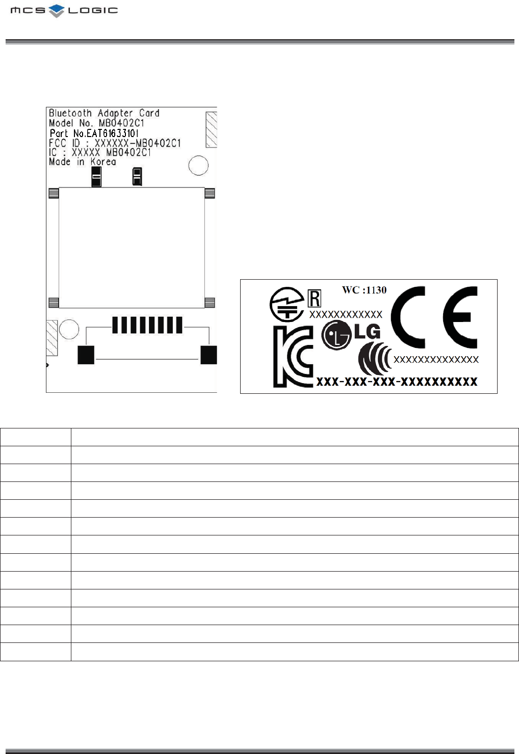
/QFWNGğU.CDGN+PHQTOCVKQP
ྙ
ྚ
ྛ
ྜ
ྜྷ
ྞ
ྟ
ྠ
ྡ
ྡྷ
ྣ
ྤ
<module silk> <label sheet>
No.
Description
ᐭ
Module Name
ᐮ
Model No. of MCSLogic
ᐯ
Part No. of LGE
ᐰ
Contains Transmitter FCC ID
ᐱ
Contains Transmitter IC
ᐲ
Manufacture Country
ᐳ
Japan’s MIC Certification Logo
ᐴ
KCC Logo
ᐵ
Week Code (YY : Year, WC : Week Code)
ᐶ
LG Logo
ᐷ
NCC Certification Logo
ᐸ
CE Certification Logo
͑͑͑͑͑͑͑͑͑͑͑͑͑͑͑͑͑͑͑͑͑͑͑͑͑͑͑͑͑͑͑͑͑͑͑͑͑͑͑͑͑͑͑͑͑͑͑͑͑͑͑͑͑͑͑͑͑͑MCSLOGIC
Product Approval Datasheet V1.00 12/19
Copyright ¤
¤
2011 MCS LOGIC Limited. All rights reserved
Confidential
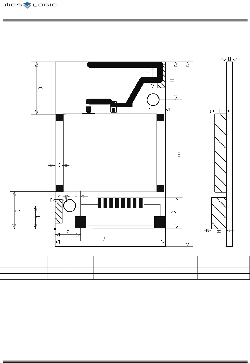
/GEJCPKECN&KOGPUKQP
TOP View
Mark
Dimension
Mark
Dimension
Mark
Dimension
Mark
Dimension
Mark
Dimension
A
18.60±0.5
D
6.30±0.3
G
5.24±0.3
J
3.90±0.3
M
1.00±0.3
B
31.20±0.3
E
3.90±0.3
H
6.40±0.3
K
1.20±0.3
N
2.60±0.3
C
8.90±0.3
F
4.30±0.3
I
2.00±0.3
L
1.80±0.3
(Unit : mm)
͑͑͑͑͑͑͑͑͑͑͑͑͑͑͑͑͑͑͑͑͑͑͑͑͑͑͑͑͑͑͑͑͑͑͑͑͑͑͑͑͑͑͑͑͑͑͑͑͑͑͑͑͑͑͑͑͑͑MCSLOGIC
Product Approval Datasheet V1.00 13/19
Copyright ¤
¤
2011 MCS LOGIC Limited. All rights reserved
Confidential
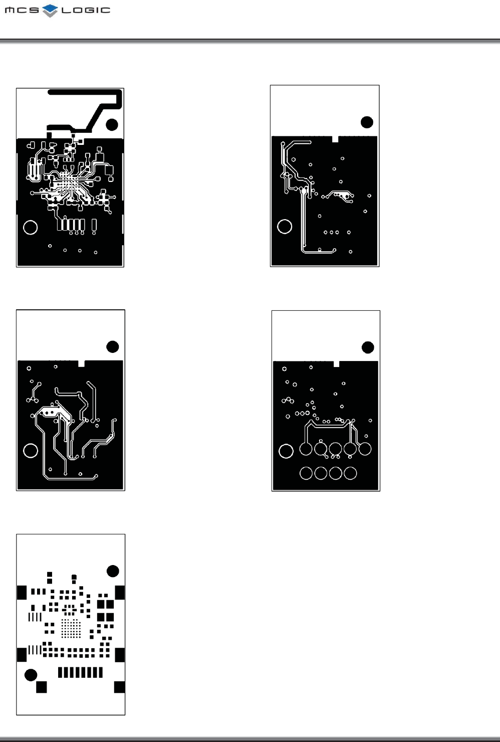
PCB LAYOUT Layer 1 PCB LAYOUT Layer 2
PCB LAYOUT Layer 3 PCB LAYOUT Layer 4
PCB Solder Mask
͑͑͑͑͑͑͑͑͑͑͑͑͑͑͑͑͑͑͑͑͑͑͑͑͑͑͑͑͑͑͑͑͑͑͑͑͑͑͑͑͑͑͑͑͑͑͑͑͑͑͑͑͑͑͑͑͑͑MCSLOGIC
Product Approval Datasheet V1.00 14/19
Copyright ¤
¤
2011 MCS LOGIC Limited. All rights reserved
Confidential
$KNNQH/CVGTKCNU
No
Q’ty
Circuit Ref
Description
Value
Package
Vendor
Part Name
1
2
R12, R13
Resistor
2.2R
1005
S.S.E
.M
RC1005J2R2CS
2
3
R10, R11,
R16
Resistor
2.2kR
1005
S.S.E.M
RC1005J
222CS
3
1
R41
Resistor
15pF
1608
S.S.E.M
CL10C150JB8NNNC
4
2
R14, R15
Resistor
100R
1005
S.S.E.M
RC1005J101CS
5
1
C20
Chip Ceramic
3.9pF
1005
S.S.E.M
CL05C3R9CB5NNNC
6
2
L10,L16
Chip
Ceramic
0.5pF
1005
S.S.E.M
CL05C0R5BB5NNNC
7
1
L11
Chip Ceramic
1pF
1005
S.S.E.M
CL05C010CB5ANNC
8
1
C19
Chip Ceramic
6.8nH
1005
S.S.E.M
CIH05T6N8JNC
9
1
C21
Chip Ceramic
10pF
1005
S.S.E.M
CL05C100CB5NNNC
10
1
C13
Chip Ceramic
1nF
1005
S.S.E.M
CL05B102JB5NNNC
11
1
C24
Chip Ceramic
220pF
1005
S.S.E.M
CL05C221FB5NNNC
12
4
C11, C12,
C16, C26
Chip Ceramic
10nF
1005
S.S.E.M
CL05B103KB5NNNC
13
3
C15, C27,
C29
Chip Ceramic
100nF
1005
S.S.E.M
CL05B104KO5NNNC
14
2
C14, C17
Chip Ceramic
100pF
1005
S.S
.E.M
CL05C101KB5NNNC
15
3
C22, C23,
C28
Chip Ceramic
1uF
1005
S.S.E.M
CL05A105KQ5NNNC
16
1
C25
Chip Ceramic
5.6nH
1005
S.S.E.M
CIH05T5N6S
17
1
L14
Chip Ceramic
10nH
1005
S.S.E.M
CIH05T10NJ
18
1
L13
Chip Ceramic
15nH
1005
S.S.E.M
CIH05T15NJ
19
1
DIODE1
0
Chip Varistor
1005
JOINSET
ECVAL1005 05E20 100NBT
20
1
U10
BT CHIP
3.8x4.0
CSR
BC41B143A07
-IXB-E4
21
1
U11
X
-TAL
26MHz
3
.2 x 2.5
PARTRON
CXC6X260000GHVRR70
22
1
U13
Balance Filter
2.0x1.25
AAC
BF24A4R218D8
23
1
U12
EEPROM
SOT-23
MICROCHIP
24AA16T-I/OT
TSSOP
GIANTEC
GT24C16-2ZLI
24
1
CON10
Connector
10031HR
-
H08
YEONHO
10031HR
-H08
25
1
Shield Can
16 X 13
HUMAN
TECH
MB0402C1_SHIELD_CAN
26
1
PCB
31.2 X 18.6 X 1
A.P.G
MB0402C1
͑͑͑͑͑͑͑͑͑͑͑͑͑͑͑͑͑͑͑͑͑͑͑͑͑͑͑͑͑͑͑͑͑͑͑͑͑͑͑͑͑͑͑͑͑͑͑͑͑͑͑͑͑͑͑͑͑͑MCSLOGIC
Product Approval Datasheet V1.00 15/19
Copyright ¤
¤
2011 MCS LOGIC Limited. All rights reserved
Confidential
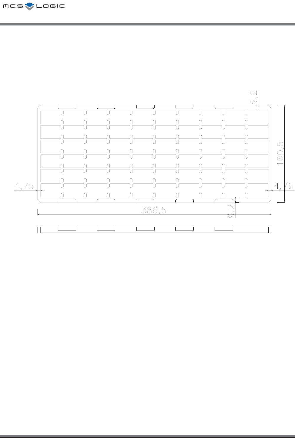
2CEMKPI+PHQTOCVKQP
6TC[
Ř
z Each tray has 60 units of products.
͑͑͑͑͑͑͑͑͑͑͑͑͑͑͑͑͑͑͑͑͑͑͑͑͑͑͑͑͑͑͑͑͑͑͑͑͑͑͑͑͑͑͑͑͑͑͑͑͑͑͑͑͑͑͑͑͑͑MCSLOGIC
Product Approval Datasheet V1.00 16/19
Copyright ¤
¤
2011 MCS LOGIC Limited. All rights reserved
Confidential
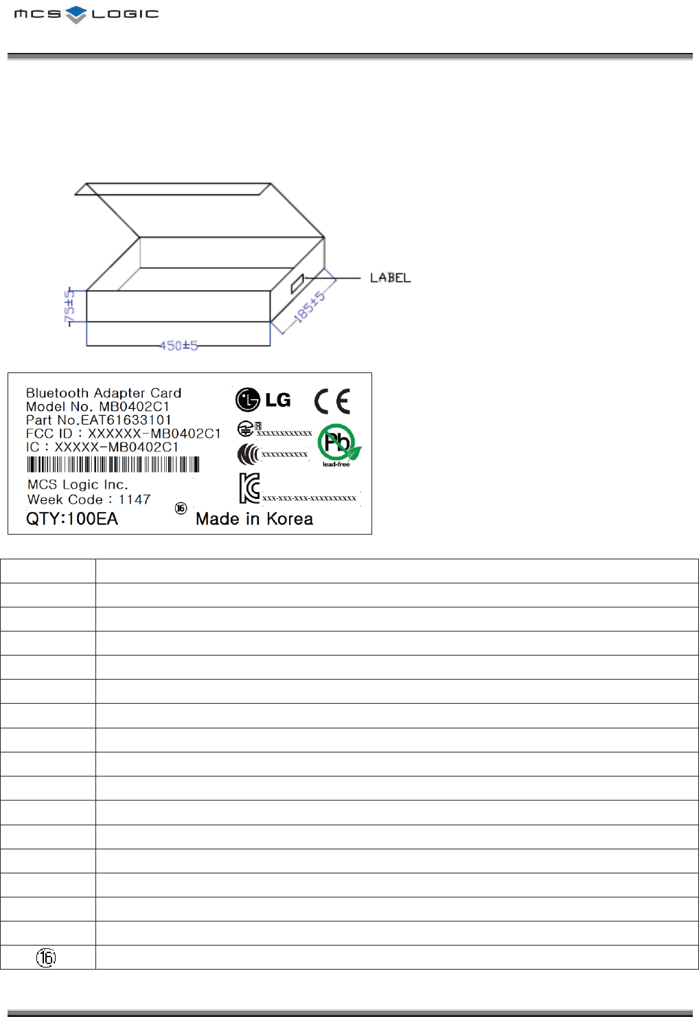
+PPGT$QZ
(Unit : mm)
¢
£
¤
¥
¦
§
¨
©
ª
«¬
®
¯
°
No.
Description
ᐭ
Module Name
ᐮ
Model No. of MCSLogic
ᐯ
Part No. of LGE
ᐰ
Contains Transmitter FCC ID
ᐱ
Contains Transmitter IC
ᐲ
Model Name Bar-Code
ᐳ
Manufacturer
ᐴ
Week Code (YY : Year, WC : Week Code)
ᐵ
Quantity
ᐶ
LG Logo
ᐷ
CE Certification Logo
ᐸ
Japan’s MIC Certification Logo
ᐹ
NCC Certification Logo
ᐺ
RoHS Logo
ᐻ
KC Logo
Manufacture Country
͑͑͑͑͑͑͑͑͑͑͑͑͑͑͑͑͑͑͑͑͑͑͑͑͑͑͑͑͑͑͑͑͑͑͑͑͑͑͑͑͑͑͑͑͑͑͑͑͑͑͑͑͑͑͑͑͑͑MCSLOGIC
Product Approval Datasheet V1.00 17/19
Copyright ¤
¤
2011 MCS LOGIC Limited. All rights reserved
Confidential
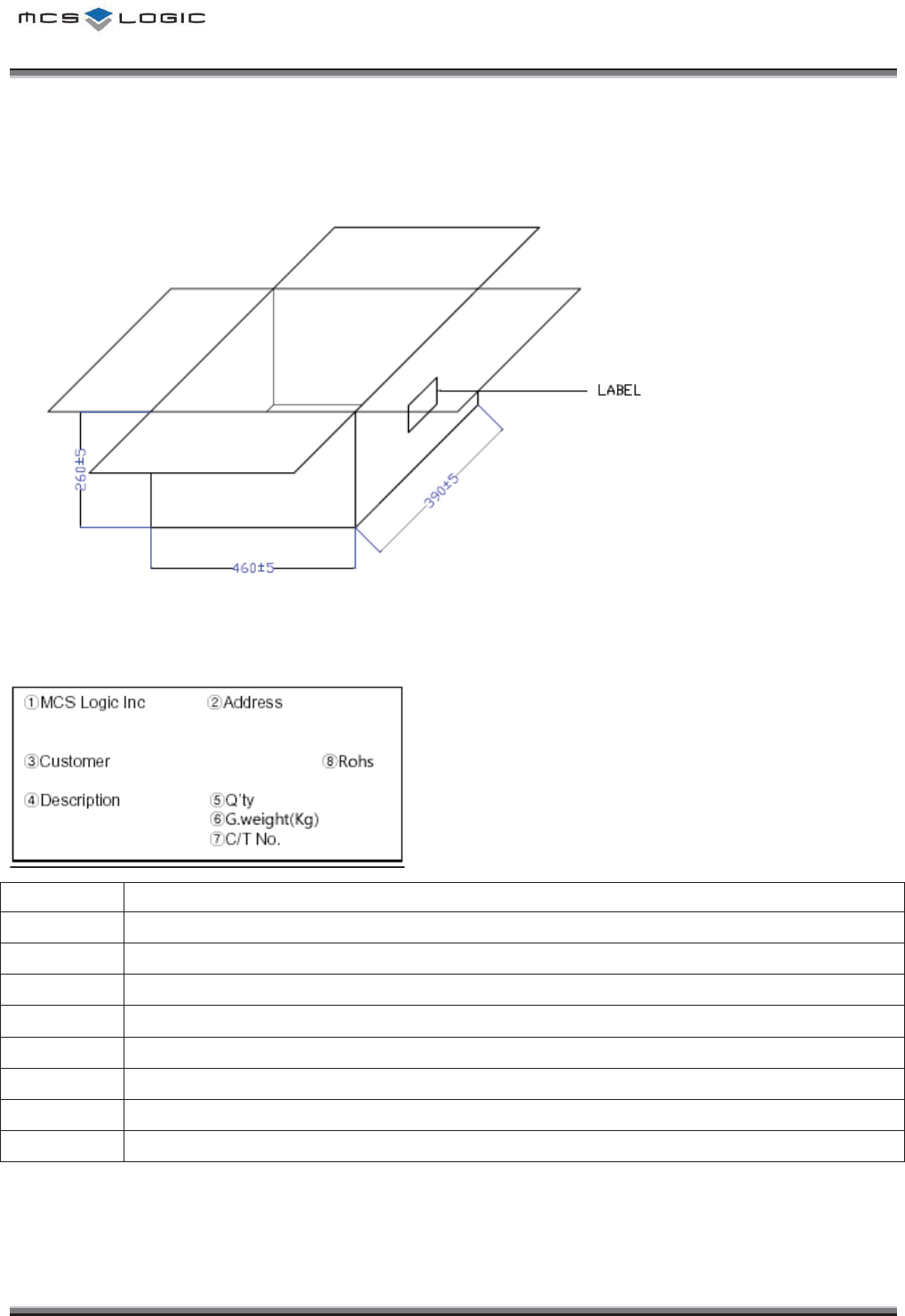
1WVVGT$QZ
(Unit : mm)
No.
Description
ᐭ
Company
ᐮ
Company Address
ᐯ
Customer
ᐰ
Model No & LGE Part No.
ᐱ
Quantity
ᐲ
Gross Weight(Kg)
ᐳ
Carton No.
ᐴ
Rohs

͑͑͑͑͑͑͑͑͑͑͑͑͑͑͑͑͑͑͑͑͑͑͑͑͑͑͑͑͑͑͑͑͑͑͑͑͑͑͑͑͑͑͑͑͑͑͑͑͑͑͑͑͑͑͑͑͑͑MCSLOGIC
Product Approval Datasheet V1.00 18/19
Copyright ¤
¤
2011 MCS LOGIC Limited. All rights reserved
Confidential
2CEMCIG4GNKCDKNKV[6GUV%QPFKVKQPU
NO
ITEM
Condition
Characteristics
1
Drop
Test
Initial value measured at standard test condition.
Test Conditions :
- Test height : 100cm
-
Test times and Directions : 10 times each in 14 directions
Drop the product onto a 10mm thickness plywood
No electrical problem
No mechanical damage
͑͑͑͑͑͑͑͑͑͑͑͑͑͑͑͑͑͑͑͑͑͑͑͑͑͑͑͑͑͑͑͑͑͑͑͑͑͑͑͑͑͑͑͑͑͑͑͑͑͑͑͑͑͑͑͑͑͑MCSLOGIC
Product Approval Datasheet V1.00 19/19
Copyright ¤
¤
2011 MCS LOGIC Limited. All rights reserved
Confidential
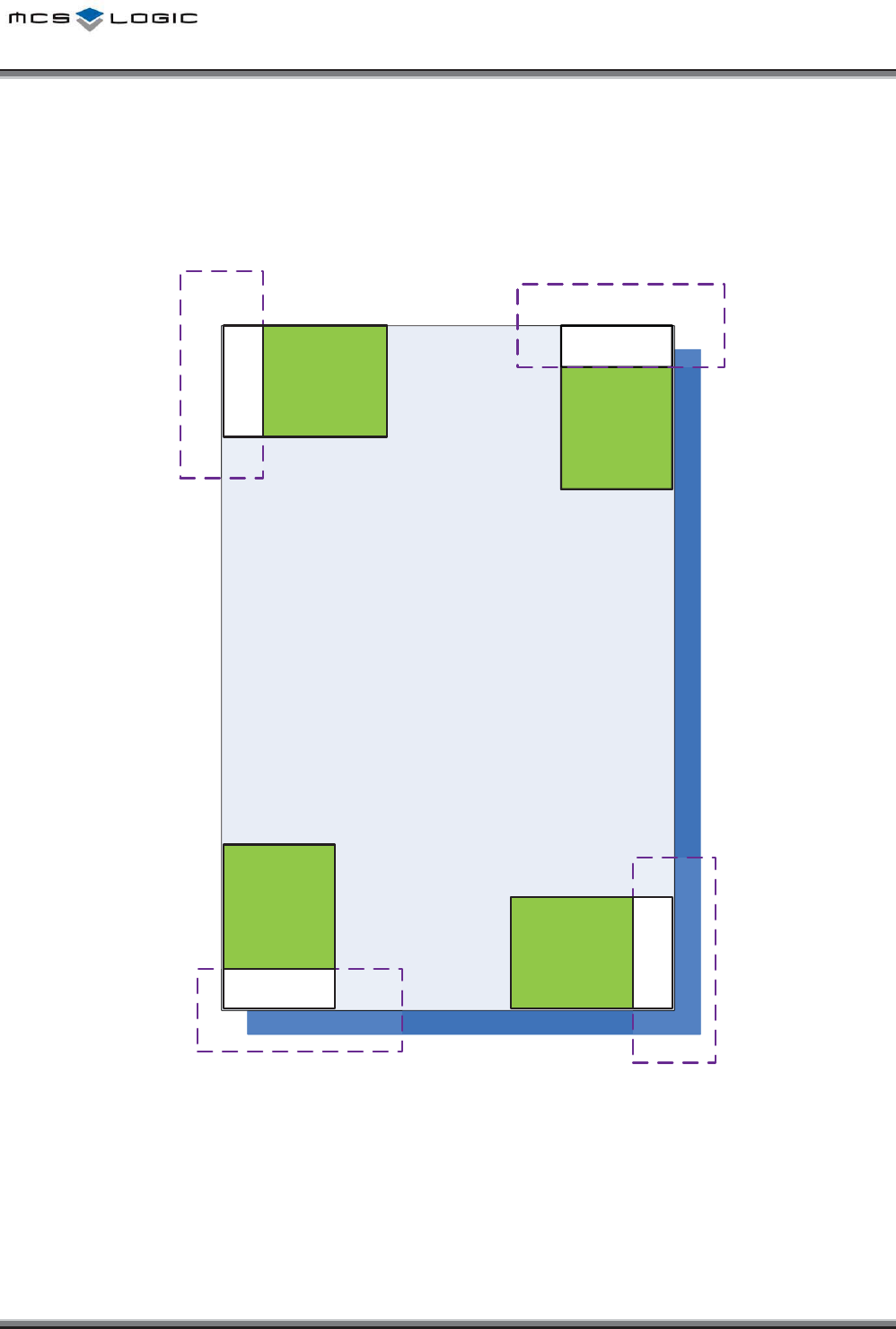
/QFWNG2QUKVKQP)WKFG
Ground & Shield CAN must not exist around Antenna area.
/$.%:
/$%:
/$%:
hu{
/$%
hu{
n
{GG
{GGnG
G
{GGnG
G
h
u
{
{GGnG
G
{GGnG
G
hu{
/$%
hu{
n
hu{
/$%
hu{
n
hu{
/$%
hu{
n

This device complies with Part 15 of the FCC Rules.This device complies with Part 15 of the FCC Rules.
Operation is subject to the following two conditions:Operation is subject to the following two conditions:
1) this device may not cause harmful interference, and1) this device may not cause harmful interference, and
2) this device must accept any interference received, including interference 2) this device must accept any interference received, including interference
that may cause undesired operation of the device.that may cause undesired operation of the device.
Id lId l
I
n
d
oor use on
lyI
n
d
oor use on
ly
FCC Caution: Any changes or modifications not expressly approved by the FCC Caution: Any changes or modifications not expressly approved by the
party responsible for compliance could void the user's authority to operate party responsible for compliance could void the user's authority to operate
this equipment.this equipment.
FCC RF Radiation Exposure Statement:FCC RF Radiation Exposure Statement:
This equipment complies with FCC radiation exposure limits set forth for an This equipment complies with FCC radiation exposure limits set forth for an
uncontrolled environment This equipment should be installed and operateduncontrolled environment This equipment should be installed and operated
uncontrolled
environment
.
This
equipment
should
be
installed
and
operated
uncontrolled
environment
.
This
equipment
should
be
installed
and
operated
with minimum distance 20 cm between the radiator & your body. with minimum distance 20 cm between the radiator & your body.
End users must follow the specific operating instructions for satisfying RF End users must follow the specific operating instructions for satisfying RF
exposure compliance. This transmitter must not be coexposure compliance. This transmitter must not be co--located or operating in located or operating in
conjunction with any other antenna or transmitterconjunction with any other antenna or transmitter
conjunction
with
any
other
antenna
or
transmitter
.
conjunction
with
any
other
antenna
or
transmitter
.

(5) (5) Industry Canada(IC) StatementIndustry Canada(IC) Statement
This device complies with RSSThis device complies with RSS--210 of the Industry Canada Rules.210 of the Industry Canada Rules.
Operation is subject to the following two conditions:Operation is subject to the following two conditions:
1) this device may not cause interference and1) this device may not cause interference and
2) this device must accept any interference. Including interference that 2) this device must accept any interference. Including interference that
may cause undesired operation of device.may cause undesired operation of device.
This class B digital apparatus complies with Canadian ICESThis class B digital apparatus complies with Canadian ICES--003003
Avis Avis d'Industried'Industrie CanadaCanada
Cet appareil est conforme à norme CNRCet appareil est conforme à norme CNR--210 des règlements d'Industrie 210 des règlements d'Industrie
Canada. Son fonctionnement est sujet aux deux conditions suivantes:Canada. Son fonctionnement est sujet aux deux conditions suivantes:
1) Cet appareil ne doit pas provoquer d'interférences et1) Cet appareil ne doit pas provoquer d'interférences et
2) Cet appareil doit accepter toute les interférences. y compris celles 2) Cet appareil doit accepter toute les interférences. y compris celles
pouvant entraîner son dyspouvant entraîner son dys--fonctionnement.fonctionnement.
Cet appareil numérique de classe B est conforme à la norme NMBCet appareil numérique de classe B est conforme à la norme NMB--003 003
du Canada.du Canada.

IC Radiation Exposure Statement:IC Radiation Exposure Statement:
This equipment complies with IC radiation exposure limits set forth for an This equipment complies with IC radiation exposure limits set forth for an
uncontrolled environment.uncontrolled environment.
This equipment should be installed and operated with minimum distanceThis equipment should be installed and operated with minimum distance
This
equipment
should
be
installed
and
operated
with
minimum
distanceThis
equipment
should
be
installed
and
operated
with
minimum
distance
20 cm between the radiator & your body.20 cm between the radiator & your body.
NOTE: THE MANUFACTURERE IS NO T RESPONSIBLE FOR ANY RADIO OR NOTE: THE MANUFACTURERE IS NO T RESPONSIBLE FOR ANY RADIO OR
TV INTERFERENCE CAUSED BY UNAUTHORIZED MODIFICATIONS TO THIS TV INTERFERENCE CAUSED BY UNAUTHORIZED MODIFICATIONS TO THIS
E
Q
UIPMENT. SUCH MODIFICATIONS COULD VOID THE USER'S AUTHORITY E
Q
UIPMENT. SUCH MODIFICATIONS COULD VOID THE USER'S AUTHORITY
QQ
TO OPERATE THE EQUIPMENT.TO OPERATE THE EQUIPMENT.
Avis d'Industrie Canada sur I'exposition aux rayonnementsAvis d'Industrie Canada sur I'exposition aux rayonnements
Cet a
pp
areil est conforme aux limites d'ex
p
osition aux ra
y
onnements Cet a
pp
areil est conforme aux limites d'ex
p
osition aux ra
y
onnements
pp p ypp p y
d'Industrie Canaca pour unenvironnement non contrôlé.d'Industrie Canaca pour unenvironnement non contrôlé.
II doit être installé de façon à garder une distance minimale de 20 II doit être installé de façon à garder une distance minimale de 20
centimètres entre la source de rayonnements et votre corps.centimètres entre la source de rayonnements et votre corps.
REMARQUE: LE FABRICANT N'EST PAS RESPONSIBLE DES INTERFÉRENCES REMARQUE: LE FABRICANT N'EST PAS RESPONSIBLE DES INTERFÉRENCES
RADIOÉLECTRIQUES CAUSÉES PAR DES MODIFICATIONS NON AUTORISÉES RADIOÉLECTRIQUES CAUSÉES PAR DES MODIFICATIONS NON AUTORISÉES
APPORTÉES APPORTÉES À CET APPAREIL. DE TELLES MODIFICATIONS APPORTÉES APPORTÉES À CET APPAREIL. DE TELLES MODIFICATIONS
POURRAIT ANNULER L'AUTORISATION ACCORDÉE À L'UTILISATEUR DE FAIRE POURRAIT ANNULER L'AUTORISATION ACCORDÉE À L'UTILISATEUR DE FAIRE
FONCTIONNER L'APPAREIL.FONCTIONNER L'APPAREIL.