LG Electronics USA 9QK-MB0402C2 Bluetooth Module User Manual operational description and
LG Electronics USA Bluetooth Module operational description and
operational description and user manual
͑͑͑͑͑͑͑͑͑͑͑͑͑͑͑͑͑͑͑͑͑͑͑͑͑͑͑͑͑͑͑͑͑͑͑͑͑͑͑͑͑͑͑͑͑͑͑͑͑͑͑͑͑͑͑͑͑͑MCSLOGIC
Product Approval Datasheet V1.00 1/19
Copyright ¤
¤
2011 MCS LOGIC Limited. All rights reserved
Confidential
241&7%6#22418#.#5*''6
241&7%6/%5.QIKE%NCUU$NWGVQQVJ/QFWNG
/1&'.0#/'/$%
%7561/'4.)'NGEVTQPKEU
%JGEMGF$[ #RRTQXGF$[ %QORCP[5GCN
MCSLOGIC
͑͑͑͑͑͑͑͑͑͑͑͑͑͑͑͑͑͑͑͑͑͑͑͑͑͑͑͑͑͑͑͑͑͑͑͑͑͑͑͑͑͑͑͑͑͑͑͑͑͑͑͑͑͑͑͑͑͑MCSLOGIC
Product Approval Datasheet V1.00 2/19
Copyright ¤
¤
2011 MCS LOGIC Limited. All rights reserved
Confidential
4GXKUKQP*KUVQT[
8GTUKQP
&CVG
4GXKUKQP&GUETKRVKQP
0.1
0.2
0.3
0.4
0.5
0.6
0.7
0.9
1.0
11/05/27
11/06/03
11/07/08
11/07/15
11/07/21
11/08/17
11/09/20
11/09/28
11/09/29
First release
Changed Pin Description
Changed Label Information
Changed Dimension
Changed BOM
Changed Mechanical Dimension
Derating release
Add PCB Layout
Changed Label Information

͑͑͑͑͑͑͑͑͑͑͑͑͑͑͑͑͑͑͑͑͑͑͑͑͑͑͑͑͑͑͑͑͑͑͑͑͑͑͑͑͑͑͑͑͑͑͑͑͑͑͑͑͑͑͑͑͑͑MCSLOGIC
Product Approval Datasheet V1.00 3/19
Copyright ¤
¤
2011 MCS LOGIC Limited. All rights reserved
Confidential
Table of Contents
1.1GENERAL DESCRIPTION .......................................................................................................................................... 4
1.2QUALITY ........................................................................................................................................................................ 4
1.3TEST ................................................................................................................................................................................ 4
1.4BLOCK DIAGRAM ....................................................................................................................................................... 5
1.5PIN DESCRIPTIONS ..................................................................................................................................................... 6
1.6ELECTRICAL CHARACTERISTICS ......................................................................................................................... 7
1.7RELIABILITY TEST CONDITIONS ........................................................................................................................ 10
1.8MODULE’S LABEL INFORMATION ...................................................................................................................... 11
1.9MECHANICAL DIMENSION .................................................................................................................................... 12
1.10BILL OF MATERIALS ............................................................................................................................................... 14
1.11PACKING INFORMATION ....................................................................................................................................... 15
1.12TRAY ............................................................................................................................................................................. 15
1.13INNER BOX .................................................................................................................................................................. 16
1.14OUTTER BOX .............................................................................................................................................................. 17
1.15PACKAGE RELIABILITY TEST CONDITIONS ................................................................................................... 18
1.16MODULE POSITION GUIDE .................................................................................................................................... 19

͑͑͑͑͑͑͑͑͑͑͑͑͑͑͑͑͑͑͑͑͑͑͑͑͑͑͑͑͑͑͑͑͑͑͑͑͑͑͑͑͑͑͑͑͑͑͑͑͑͑͑͑͑͑͑͑͑͑MCSLOGIC
Product Approval Datasheet V1.00 4/19
Copyright ¤
¤
2011 MCS LOGIC Limited. All rights reserved
Confidential
)GPGTCN&GUETKRVKQP
MB0402C is a fully integrated Bluetooth module. It is based on CSR’s Bluecore4-ROM with
specific interface design to meet LG Electronics’s needs.
MB0402C is compatible with Bluetooth specification version 2.1. It integrates RF, Baseband
controller, etc., a completed Bluetooth subsystem.
(GCVWTGU
͞ Operation Range (Class II) : 10 meters
͞ Operating Temperature Range : -10ఁ ~ 80ఁ
͞ Operating VDD Range : 3.0 V ~ 3.6V
͞ Interface : UART
͞ Internal Antenna
͞ Fully Compatible with Bluetooth Specification 2.1
͞ RoHS Compliant
#RRNKECVKQPU
͞ Consumer Products
3WCNKV[
Qaulity should meet each condition which mentioned on this specification. However, the items
which are not mentioned on this specification follow the inspection agreements and standards
which are agree with both companies.
6GUV
Electrical characteristics are tested for every products. However, if there are any objection in
judgement, it should be treated with agreements of companies.
͑͑͑͑͑͑͑͑͑͑͑͑͑͑͑͑͑͑͑͑͑͑͑͑͑͑͑͑͑͑͑͑͑͑͑͑͑͑͑͑͑͑͑͑͑͑͑͑͑͑͑͑͑͑͑͑͑͑MCSLOGIC
Product Approval Datasheet V1.00 6/19
Copyright ¤
¤
2011 MCS LOGIC Limited. All rights reserved
Confidential
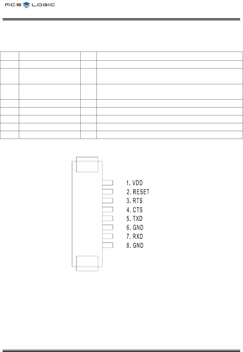
2KP&GUETKRVKQPU
No
Pin Name
I/O
Description
1
VDD
I
Positive Input for the internal regulator (3.0 ~ 3.6V)
2
RESET
I
Reset if low. Input debounced so must be low for >5ms to
cause a reset
3
RTS
O
Bluetooth UART Request to Send.
Active-low request.
4
CTS
I
Bluetooth UART Clear to Send.Active-low clear.
5
TXD
O
Bluetooth UART Serial Output.
6
GND
-
Ground.
7
RXD
I
Bluetooth UART Serial Input.
8
GND
-
Ground
͑͑͑͑͑͑͑͑͑͑͑͑͑͑͑͑͑͑͑͑͑͑͑͑͑͑͑͑͑͑͑͑͑͑͑͑͑͑͑͑͑͑͑͑͑͑͑͑͑͑͑͑͑͑͑͑͑͑MCSLOGIC
Product Approval Datasheet V1.00 7/19
Copyright ¤
¤
2011 MCS LOGIC Limited. All rights reserved
Confidential
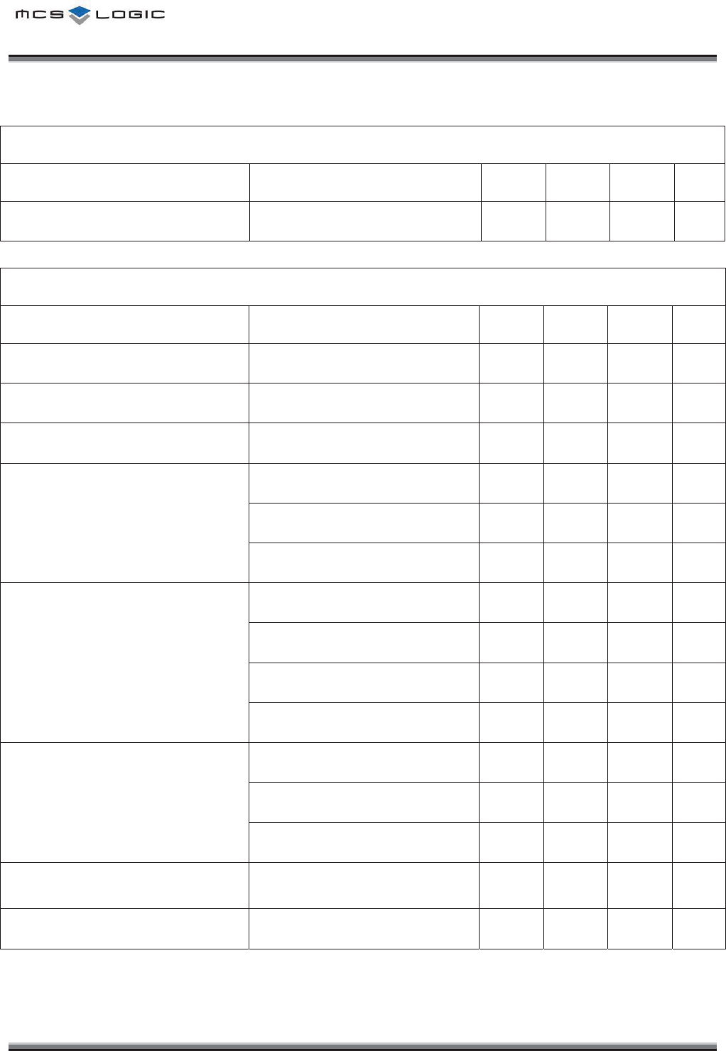
'NGEVTKECN%JCTCEVGTKUVKEU
Conditions : VDD = 3.3V, Ta = 25 ଇ, unless otherwise noted.
Absolute Maximum Ratings
Parameter
Min
Max
Unit
Power Supply Voltage : VDD -0.4V 3.6V DCV
Storage Temperature -40 85 ఁ
Recommended Operating Conditions
Parameter
Min
Max
Unit
Power Supply Voltage 3.0V 3.6V DCV
Operation Temperature -10 80 ఁ
Current consumption
Parameter
Avg
Peak
Unit
Standby
0.3
-
mA
TX-CW
57.6
63
mA
TX-Modulation
36
63
mA
RX
37.9
-
mA
Input/Output Characteristics
Parameter
Min
Max
Unit
VIL Input Voltage Low -0.4 0.8 V
VIH Input Voltage High 0.7*VDD VDD+0.4 V
VOL Output Voltage Low - 0.2 V
VOH Output Voltage High VDD-0.2 - V
͑͑͑͑͑͑͑͑͑͑͑͑͑͑͑͑͑͑͑͑͑͑͑͑͑͑͑͑͑͑͑͑͑͑͑͑͑͑͑͑͑͑͑͑͑͑͑͑͑͑͑͑͑͑͑͑͑͑MCSLOGIC
Product Approval Datasheet V1.00 8/19
Copyright ¤
¤
2011 MCS LOGIC Limited. All rights reserved
Confidential
General Performance
Parameter
Condition
Min
Type
Max
Unit
Frequency Range
2402
2480
MHz
Transmitter Performance
Parameter
Condition
Min
Type
Max
Unit
Transmit Power -6 0 4
dBm
Power density - - 20
dBm
20dB bandwidth
1000
KHz
Adjacent channel power
±2% - - -20
dBm
±3% - - -40
dBm
±4% - - -40
dBm
Out-band Spurious Emission
30MHz ~ 1GHz - - -36
dBm
1GHz ~ 12.75GHz - - -30
dBm
1.8GHz ~ 1.9GHz - - -47
dBm
5.1GHz ~ 5.3GHz - - -47
dBm
Modulation Characteristic
∆F1avg 140
- 175
KHz
∆F2max 115
- -
KHz
∆F2avg / ∆F1avg 80
- - %
Initial Carrier Frequency
Tolerance
DH1 packet -75
- 75
KHz
Carrier Frequency Drift DH5 packet -25
25
KHz
͑͑͑͑͑͑͑͑͑͑͑͑͑͑͑͑͑͑͑͑͑͑͑͑͑͑͑͑͑͑͑͑͑͑͑͑͑͑͑͑͑͑͑͑͑͑͑͑͑͑͑͑͑͑͑͑͑͑MCSLOGIC
Product Approval Datasheet V1.00 9/19
Copyright ¤
¤
2011 MCS LOGIC Limited. All rights reserved
Confidential
Receiver Performance
Parameter
Condition
Min
Type
Max
Unit
Sensitivity at 0.1% BER
Single slot
(DH1 packet)
-70
- -
dBm
Sensitivity at 0.1% BER
Multi slot
(DH5 packet)
-70
- -
dBm
Maximum received signal at 0.1% BER
-20
- -
dBm
Maximum level of intermodulation
interferers
f1-f2 = 5 MHz,
Pwanted= -64 dBm
-39
- -
dBm
Derating
NO
ITEM SIZE VALUE
RATED
V/C/W
INPUT
VOLTAGE
INPUT
CURRENT
USAGE
RATIO
1
CL05F105ZQ5NNNC
1.0 X 0.5
1uF
6.3V
3.3V
-
52.38%
2
CL05B103KB5NNNC
1.0 X 0.5
10nF
50V
3.3V
-
6.60%
3
CL05B104KO5NNNC
1.0 X 0.5
100nF
50V
3.3V
-
6.60%
4
RC1005J222CS
1.0 X 0.5
2.2KΩ
1/16W
3.3V
0.0001%
5
CIH05T15NJ
1.0 X 0.5
15nH
300mA
3.3V
60mA
20%
6
CIH05T10NJ
1.0 X 0.5
10nH
300mA
1.8V
<0.01uA
<0.033%
7
CL05C221FB5NNNC
1.0 X 0.5
220pF
50V
1.8V
3.6%
8
CL05B103KB5NNNC
1.0 X 0.5
10nF
50V
1.8V
3.6%
9
CL05B104KO5NNNC
1.0 X 0.5
100nF
50V
1.8V
3.6%
10
CL05F105ZQ5NNNC
1.0 X 0.5
1uF
6.3V
1.8V
28.57%
͑͑͑͑͑͑͑͑͑͑͑͑͑͑͑͑͑͑͑͑͑͑͑͑͑͑͑͑͑͑͑͑͑͑͑͑͑͑͑͑͑͑͑͑͑͑͑͑͑͑͑͑͑͑͑͑͑͑MCSLOGIC
Product Approval Datasheet V1.00 10/19
Copyright ¤
¤
2011 MCS LOGIC Limited. All rights reserved
Confidential
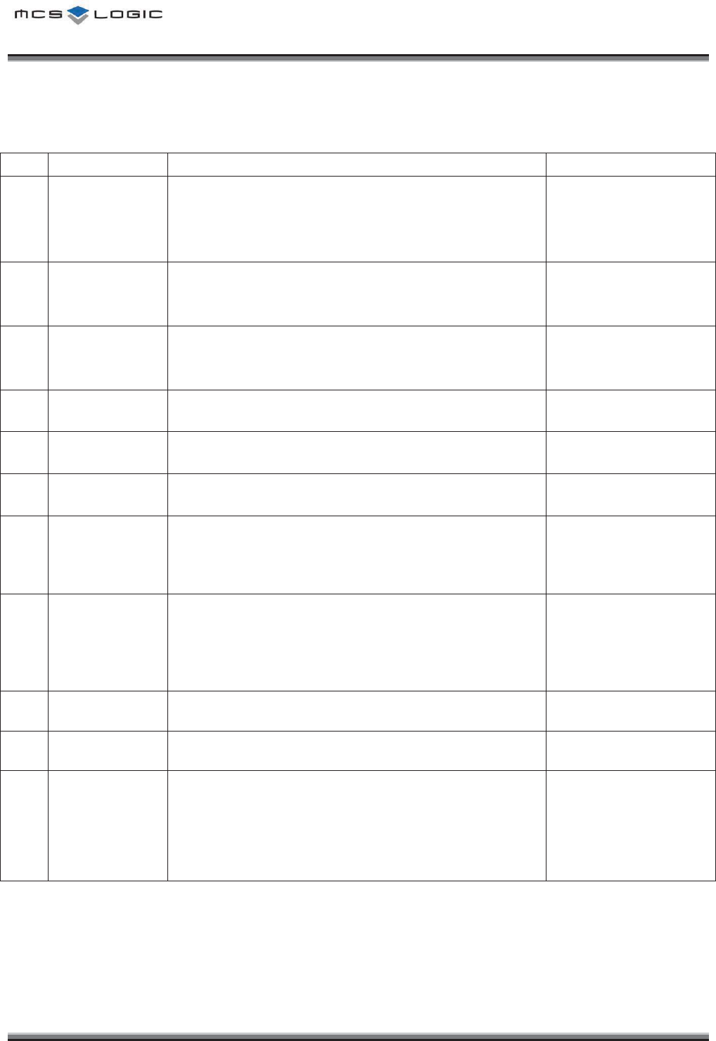
4GNKCDKNKV[6GUV%QPFKVKQPU
NO
ITEM
Condition
Characteristics
1
Constant
Humidity
Load Test
Initial value measured at standard test condition
Test Conditions : 35ఁ, 90% RH, 100hr
25ఁ, 50% RH, 2hr
Supply Voltage Condition : standard ρ5%
No electrical problem
2
High Temp
Load Test
Initial value measured at standard test condition.
Test Conditions : 25ఁ Î 85ఁ, 100hr (Within 1hr)
Supply Voltage Condition : standard ρ5%
No electrical problem
3
Low Temp
Load Test
Initial value measured at standard test condition.
Test Conditions : 25ఁ Î -40ఁ, 100hr (Within 1hr)
Supply Voltage Condition : standard ρ5%
No electrical problem
4
High Temp
Storage Test
Initial value measured at standard test condition.
Test Conditions : 85ఁ, 100hr
No electrical problem
5
Low Temp
Storage Test
Initial value measured at standard test condition.
Test Conditions : -40ఁ, 100hr
No electrical problem
6
Temperature
Cycle
Initial value measured at standard test condition.
Test Conditions : -40ఁ Î 85ఁ, 15min, 50cycle
No electrical problem
7
Vibration
Test
Initial value measured at standard test condition.
Test Conditions :
- Freq : 10~55Hz, acceleration: 5G (Sine wave vibration)
- Test time : X, Y, Z axis for 2hr
No electrical problem
No mechanical damage
8
Drop
Test
Initial value measured at standard test condition.
Test Conditions :
- Test height : 100cm
- Test times : 10 times
Drop the product onto a 10mm thickness plywood
No electrical problem
No mechanical damage
9
ESD HBM
Initial value measured at standard test condition.
Test Conditions : 2000V
No electrical problem
No mechanical damage
10
ESD MM
Initial value measured at standard test condition.
Test Conditions : 200V
No electrical problem
No mechanical damage
11
Temperature
Rising Test
Initial value measured at standard test condition.
Test Conditions : 40ఁ, 2hr
Module Condition : A2DP Stream
BT IC : 42.1ఁ
EEPROM : 42ఁ
Crystal : 42.2ఁ
PCB : 41.2ఁ
Connector : 41.1ఁ
͑͑͑͑͑͑͑͑͑͑͑͑͑͑͑͑͑͑͑͑͑͑͑͑͑͑͑͑͑͑͑͑͑͑͑͑͑͑͑͑͑͑͑͑͑͑͑͑͑͑͑͑͑͑͑͑͑͑MCSLOGIC
Product Approval Datasheet V1.00 11/19
Copyright ¤
¤
2011 MCS LOGIC Limited. All rights reserved
Confidential
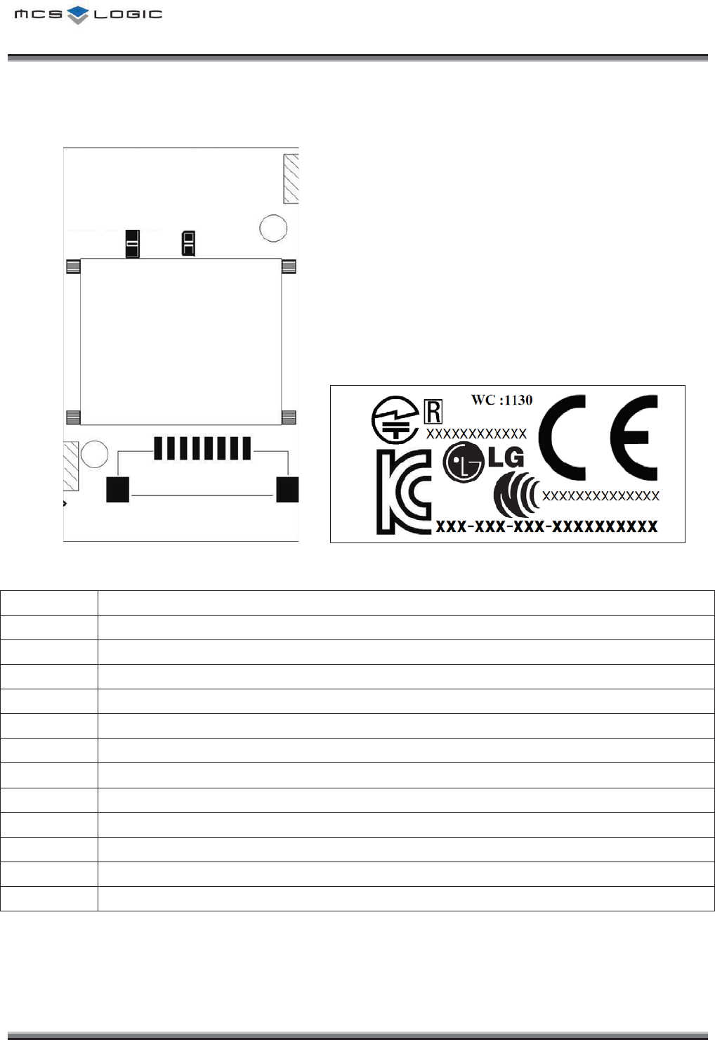
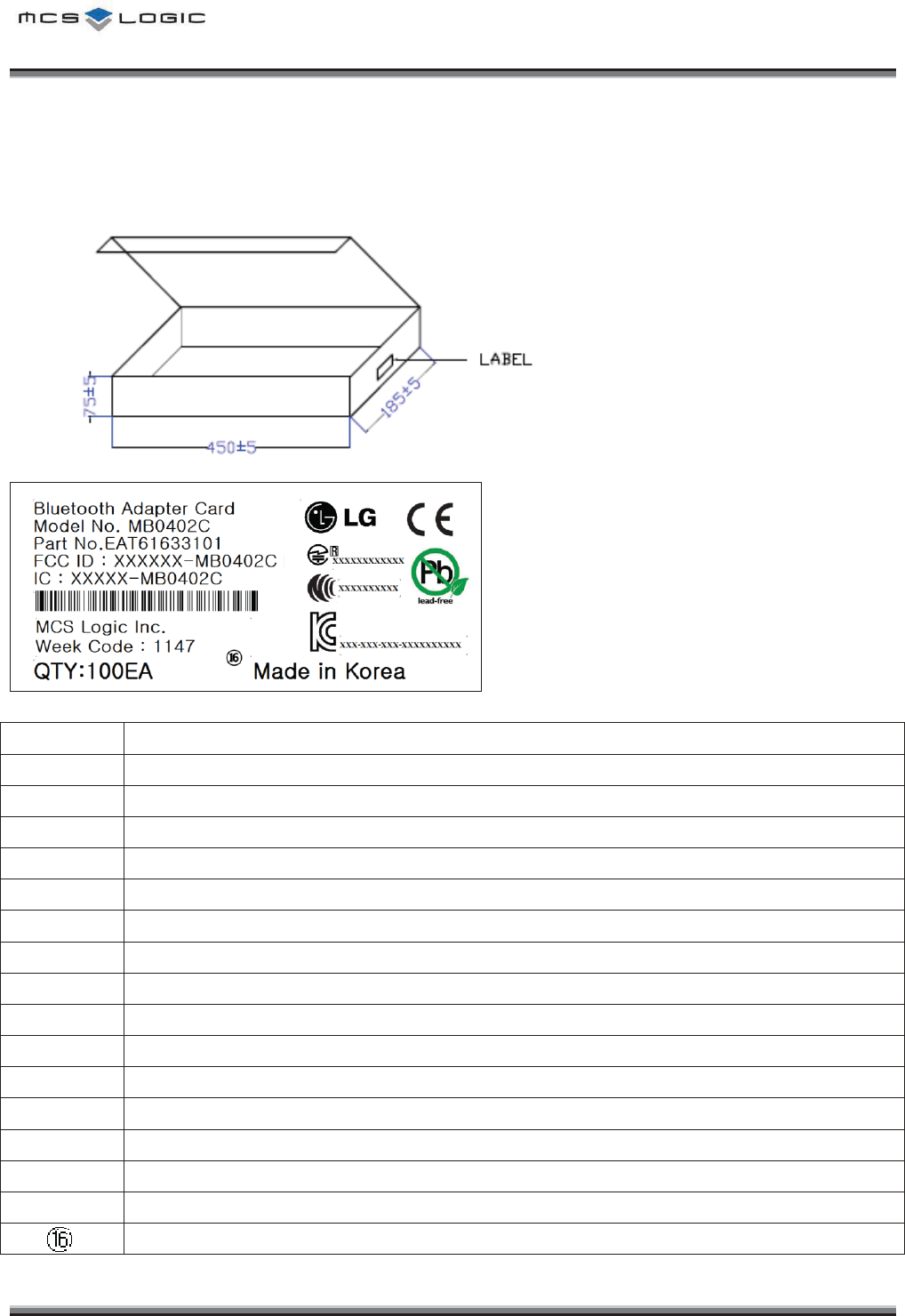
/QFWNGğU.CDGN+PHQTOCVKQP
ྙ
ྚ
ྛ
ྜ
ྜྷ
ྞ
ྟ
ྠ
ྡ
ྡྷ
ྣ
ྤ
<module silk> <label sheet>
No.
Description
ᐭ
Module Name
ᐮ
Model No. of MCSLogic
ᐯ
Part No. of LGE
ᐰ
Contains Transmitter FCC ID
ᐱ
Contains Transmitter IC
ᐲ
Manufacture Country
ᐳ
Japan’s MIC Certification Logo
ᐴ
KCC Logo
ᐵ
Week Code (YY : Year, WC : Week Code)
ᐶ
LG Logo
ᐷ
NCC Certification Logo
ᐸ
CE Certification Logo
͑͑͑͑͑͑͑͑͑͑͑͑͑͑͑͑͑͑͑͑͑͑͑͑͑͑͑͑͑͑͑͑͑͑͑͑͑͑͑͑͑͑͑͑͑͑͑͑͑͑͑͑͑͑͑͑͑͑MCSLOGIC
Product Approval Datasheet V1.00 12/19
Copyright ¤
¤
2011 MCS LOGIC Limited. All rights reserved
Confidential
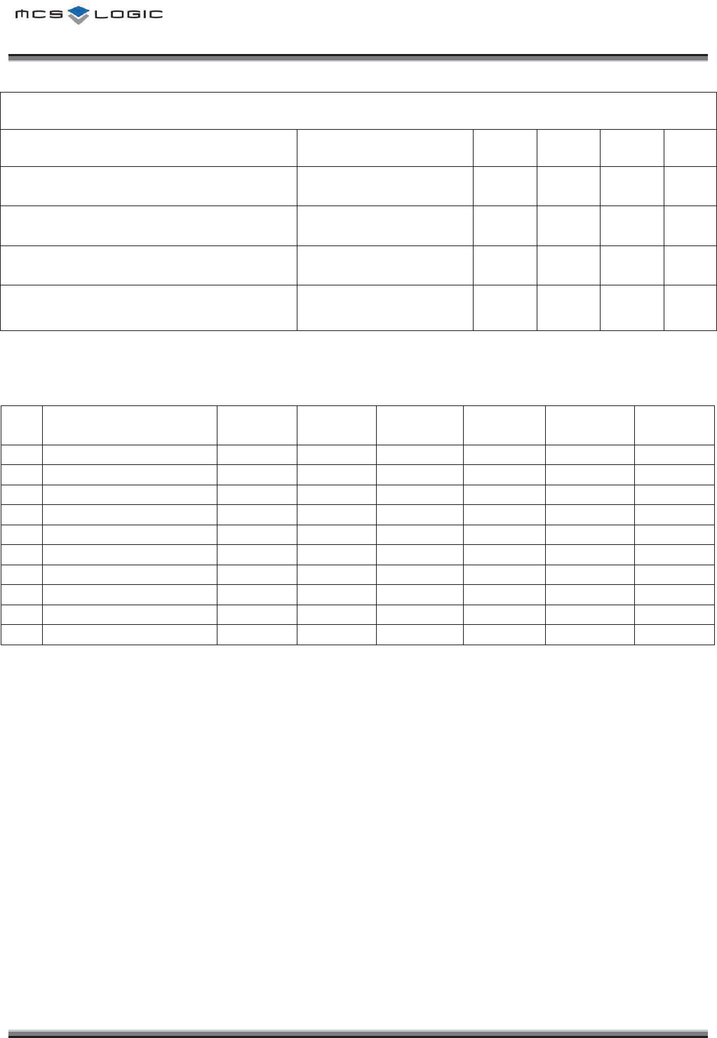
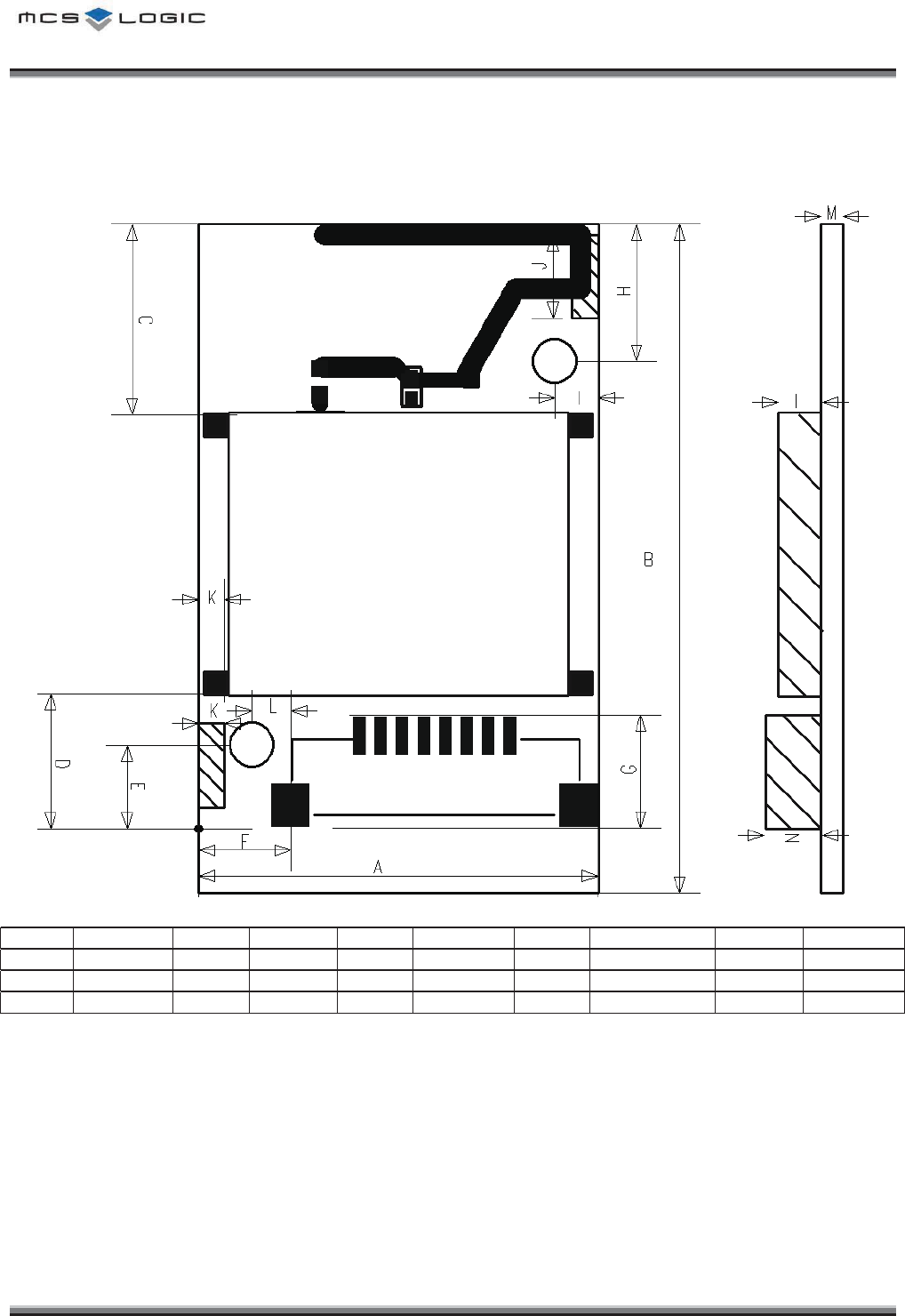
/GEJCPKECN&KOGPUKQP
TOP View
Mark
Dimension
Mark
Dimension
Mark
Dimension
Mark
Dimension
Mark
Dimension
A
18.60±0.5
D
6.30±0.3
G
5.24±0.3
J
3.90±0.3
M
1.00±0.3
B
31.20±0.3
E
3.90±0.3
H
6.40±0.3
K
1.20±0.3
N
2.60±0.3
C
8.90±0.3
F
4.30±0.3
I
2.00±0.3
L
1.80±0.3
(Unit : mm)
͑͑͑͑͑͑͑͑͑͑͑͑͑͑͑͑͑͑͑͑͑͑͑͑͑͑͑͑͑͑͑͑͑͑͑͑͑͑͑͑͑͑͑͑͑͑͑͑͑͑͑͑͑͑͑͑͑͑MCSLOGIC
Product Approval Datasheet V1.00 13/19
Copyright ¤
¤
2011 MCS LOGIC Limited. All rights reserved
Confidential
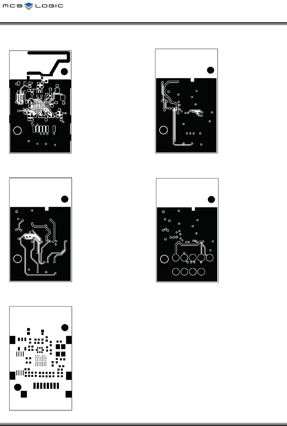
PCB LAYOUT Layer 1 PCB LAYOUT Layer 2
PCB LAYOUT Layer 3 PCB LAYOUT Layer 4
PCB Solder Mask
This metallic pads are not used in final products.
͑͑͑͑͑͑͑͑͑͑͑͑͑͑͑͑͑͑͑͑͑͑͑͑͑͑͑͑͑͑͑͑͑͑͑͑͑͑͑͑͑͑͑͑͑͑͑͑͑͑͑͑͑͑͑͑͑͑MCSLOGIC
Product Approval Datasheet V1.00 14/19
Copyright ¤
¤
2011 MCS LOGIC Limited. All rights reserved
Confidential
$KNNQH/CVGTKCNU
No Q’ty Circuit Ref Description Value Package Vendor Part Name
1 2 R12, R13 Resistor 2.2R 1005 S.S.E.M RC1005J2R2CS
2 3 R10, R11,
R16 Resistor 2.2kR 1005 S.S.E.M RC1005J222CS
3 1 R41 Resistor 15pF 1608 S.S.E.M CL10C150JB8NNNC
4 2 R14, R15 Resistor 100R 1005 S.S.E.M RC1005J101CS
5 1 C20 Chip Ceramic 3.9pF 1005 S.S.E.M CL05C3R9CB5NNNC
6 2 L10,L16 Chip Ceramic 0.5pF 1005 S.S.E.M CL05C0R5BB5NNNC
7 1 L11 Chip Ceramic 1pF 1005 S.S.E.M CL05C010CB5ANNC
8 1 C19 Chip Ceramic 6.8nH 1005 S.S.E.M CIH05T6N8JNC
9 1 C21 Chip Ceramic 10pF 1005 S.S.E.M CL05C100CB5NNNC
10 1 C13 Chip Ceramic 1nF 1005 S.S.E.M CL05B102JB5NNNC
11 1 C24 Chip Ceramic 220pF 1005 S.S.E.M CL05C221FB5NNNC
12 4 C11, C12,
C16, C26 Chip Ceramic 10nF 1005 S.S.E.M CL05B103KB5NNNC
13 3 C15, C27,
C29 Chip Ceramic 100nF 1005 S.S.E.M CL05B104KO5NNNC
14 2 C14, C17 Chip Ceramic 100pF 1005 S.S.E.M CL05C101KB5NNNC
15 3 C22, C23,
C28 Chip Ceramic 1uF 1005 S.S.E.M CL05A105KQ5NNNC
16 1 C25 Chip Ceramic 5.6nH 1005 S.S.E.M CIH05T5N6S
17 1 L14 Chip Ceramic 10nH 1005 S.S.E.M CIH05T10NJ
18 1 L13 Chip Ceramic 15nH 1005 S.S.E.M CIH05T15NJ
19 1 DIODE10 Chip Varistor
1005 JOINSET
ECVAL1005 05E20 100NBT
20 1 U10 BT CHIP 3.8x4.0 CSR BC41B143A07-IXB-E4
21 1 U11 X-TAL 26MHz 3.2 x 2.5 PARTRON CXC6X260000GHVRR70
22 1 U13 Balance Filter
2.0x1.25 AAC BF24A4R218D8
23 1 U12 EEPROM
SOT-23 MICROCHIP 24AA16T-I/OT
TSSOP GIANTEC GT24C16-2ZLI
24 1 CON10 Connector 10031HR-H08 YEONHO 10031HR-H08
25 1 Shield Can 16 X 13 HUMAN
TECH MB0402C_SHIELD_CAN
26 1 PCB 31.2 X 18.6 X 1 A.P.G MB0402C
͑͑͑͑͑͑͑͑͑͑͑͑͑͑͑͑͑͑͑͑͑͑͑͑͑͑͑͑͑͑͑͑͑͑͑͑͑͑͑͑͑͑͑͑͑͑͑͑͑͑͑͑͑͑͑͑͑͑MCSLOGIC
Product Approval Datasheet V1.00 15/19
Copyright ¤
¤
2011 MCS LOGIC Limited. All rights reserved
Confidential
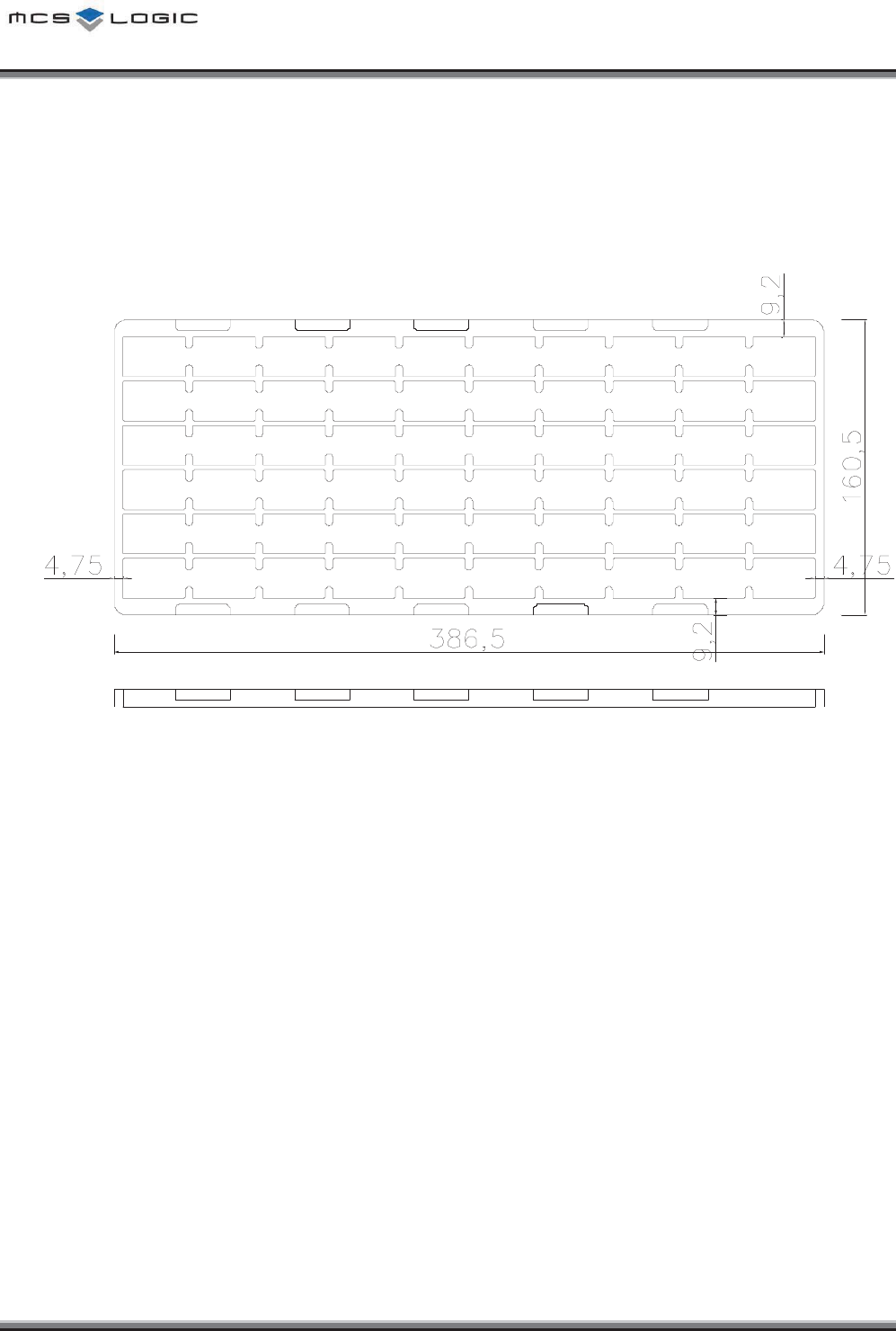
2CEMKPI+PHQTOCVKQP
6TC[
Ř
z Each tray has 60 units of products.
͑͑͑͑͑͑͑͑͑͑͑͑͑͑͑͑͑͑͑͑͑͑͑͑͑͑͑͑͑͑͑͑͑͑͑͑͑͑͑͑͑͑͑͑͑͑͑͑͑͑͑͑͑͑͑͑͑͑MCSLOGIC
Product Approval Datasheet V1.00 16/19
Copyright ¤
¤
2011 MCS LOGIC Limited. All rights reserved
Confidential
+PPGT$QZ
(Unit : mm)
¢
£
¤
¥
¦
§
¨
©
ª
«¬
®
¯
°
No.
Description
ᐭ
Module Name
ᐮ
Model No. of MCSLogic
ᐯ
Part No. of LGE
ᐰ
Contains Transmitter FCC ID
ᐱ
Contains Transmitter IC
ᐲ
Model Name Bar-Code
ᐳ
Manufacturer
ᐴ
Week Code (YY : Year, WC : Week Code)
ᐵ
Quantity
ᐶ
LG Logo
ᐷ
CE Certification Logo
ᐸ
Japan’s MIC Certification Logo
ᐹ
NCC Certification Logo
ᐺ
RoHS Logo
ᐻ
KC Logo
Manufacture Country
͑͑͑͑͑͑͑͑͑͑͑͑͑͑͑͑͑͑͑͑͑͑͑͑͑͑͑͑͑͑͑͑͑͑͑͑͑͑͑͑͑͑͑͑͑͑͑͑͑͑͑͑͑͑͑͑͑͑MCSLOGIC
Product Approval Datasheet V1.00 17/19
Copyright ¤
¤
2011 MCS LOGIC Limited. All rights reserved
Confidential
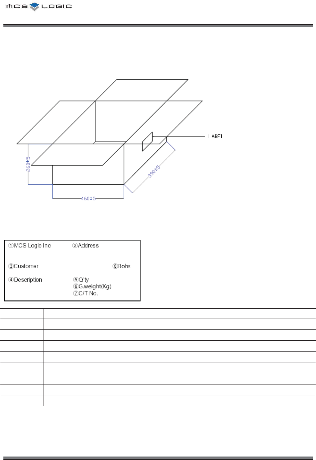
1WVVGT$QZ
(Unit : mm)
No.
Description
ᐭ
Company
ᐮ
Company Address
ᐯ
Customer
ᐰ
Model No & LGE Part No.
ᐱ
Quantity
ᐲ
Gross Weight(Kg)
ᐳ
Carton No.
ᐴ
Rohs

͑͑͑͑͑͑͑͑͑͑͑͑͑͑͑͑͑͑͑͑͑͑͑͑͑͑͑͑͑͑͑͑͑͑͑͑͑͑͑͑͑͑͑͑͑͑͑͑͑͑͑͑͑͑͑͑͑͑MCSLOGIC
Product Approval Datasheet V1.00 18/19
Copyright ¤
¤
2011 MCS LOGIC Limited. All rights reserved
Confidential
2CEMCIG4GNKCDKNKV[6GUV%QPFKVKQPU
NO
ITEM
Condition
Characteristics
1
Drop
Test
Initial value measured at standard test condition.
Test Conditions :
- Test height : 100cm
-
Test times and Directions : 10 times each in 14 directions
Drop the product onto a 10mm thickness plywood
No electrical problem
No mechanical damage
͑͑͑͑͑͑͑͑͑͑͑͑͑͑͑͑͑͑͑͑͑͑͑͑͑͑͑͑͑͑͑͑͑͑͑͑͑͑͑͑͑͑͑͑͑͑͑͑͑͑͑͑͑͑͑͑͑͑MCSLOGIC
Product Approval Datasheet V1.00 19/19
Copyright ¤
¤
2011 MCS LOGIC Limited. All rights reserved
Confidential
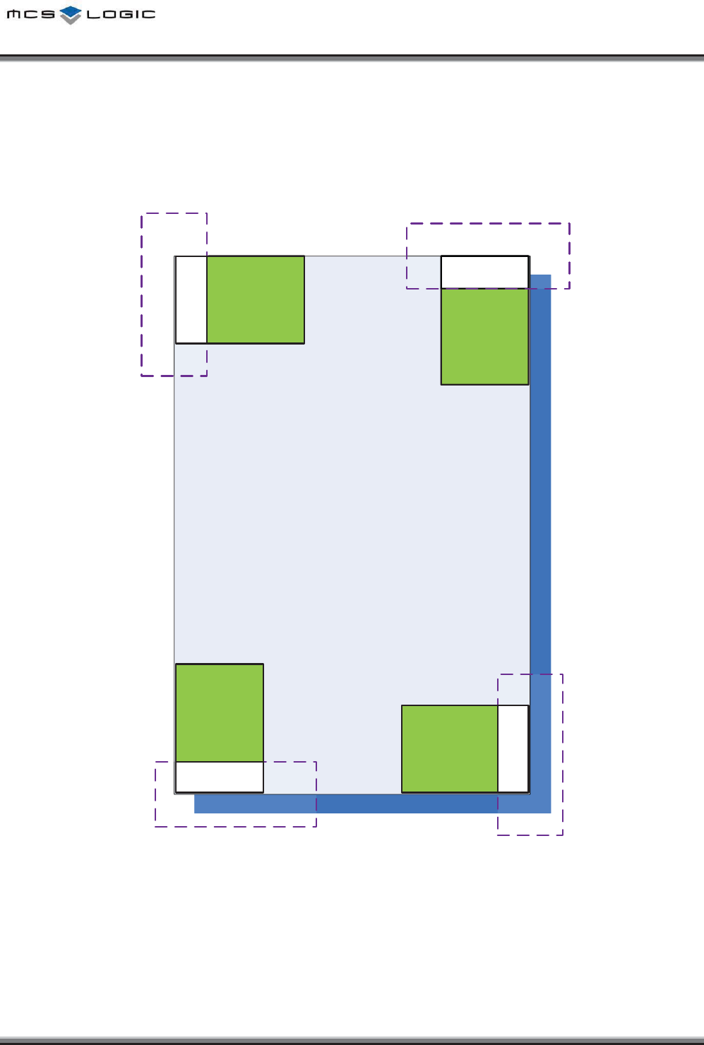
/QFWNG2QUKVKQP)WKFG
Ground & Shield CAN must not exist around Antenna area.
/$.%:
/$%:
/$%:
hu{
/$%
hu{
n
{GG
{GGnG
G
{GGnG
G
h
u
{
{GGnG
G
{GGnG
G
hu{
/$%
hu{
n
hu{
/$%
hu{
n
hu{
/$%
hu{
n
Approval Statements
CE approval
Hereby, we declare that this device is in compliance with the essential requirements and other relevant provisions of directive 1999/5/EC.
Restrictions of use: In France, this device must not be used outdoors.
FCC approval
This device complies with Part 15 of the FCC`s Rules. Operation is subject to the following two Conditions:
1. This device may not cause harmful interference, and
2. This device must accept any interference received, including interference that may cause undesirable operation.
To satisfy FCC exterior labeling requirements, the following text must be placed on the exterior of the end product.
Contains Transmitter module FCC ID: BEJ9QK-MB0402C2
This equipment has been tested and found to comply with the limits for a Class B digital device, pursuant to part 15 of the FCC Rules.
These limits are designed to provide reasonable protection against harmful interference in a residential installation. This equipment
generates, uses and can radiate radio frequency energy and, if not installed and used in accordance with the instructions, may cause
harmful interference to radio communications. However, there is no guarantee that interference will not occur in a particular installation. If
this equipment does cause harmful interference to radio or television reception, which can be determined by turning the equipment off and
on, the user is encouraged to try to correct the interference by one or more of the following measures:
Reorient or relocate the receiving antenna.
Increase the separation between the equipment and receiver.
Connect the equipment into an outlet on a circuit different from that to which the receiver is connected.
Consult the dealer or an experienced radio/ TV technician for help.
IC approval
This device complies with Industry Canada license-exempt RSS standard(s). Operation is subject to the following two conditions: (1) this
device may not cause interference, and (2) this device must accept any interference, including interference that may cause undesired
operation of the device.
Cet appareil est conforme avec Industrie Canada exempts de licence standard RSS (s). L'opération est soumise aux deux conditions
suivantes: (1) cet appareil ne peut causer d'interférences, et (2) cet appareil doit accepter toute interférence, y compris les interférences qui
peuvent causer un mauvais fonctionnement de l'appareil.
The host device must be labeled to display the Industry Canada certification number of the module.
Contains transmitter module IC: 2703H-MB0402C2
Le dispositif d'accueil doivent être étiquetés pour afficher le numéro de certification d'Industrie Canada du module.
Contient module émetteur IC : 2703H-MB0402C2

User information
Caution: Any changed or modifications not expressly approved by the party responsible for compliance could void the user`s
authority to operate this equipment.
Attention: Toute changé ou modifications non expressément approuvés par la partie responsable de la conformité pourraient
annuler l'utilisateur `autorité de faire fonctionner cet équipement.
IMPORTANT NOTE
This device complies with FCC & IC radiation exposure limits set forth for an uncontrolled environment. This device should be installed and
must not be co-located or operating in conjunction with any other antenna or transmitter.
This device is intended only for OEM integrators under the following conditions:
1) This module may not be co-located with any other transmitters or antennas.
As long as 2 conditions above are met, further transmitter test will not be required. However, the OEM integrator is still responsible for
testing their end-product for any additional compliance requirements with this module installed.
In the event that these conditions cannot be met, then the FCC & IC authorizations are no longer considered valid and the FCC ID cannot
be used on the final product. In these circumstances, the OEM integrator will be responsible for re-evaluating the end product including this
module and obtaining separate FCC & IC authorizations.
NOTE IMPORTANTE
Cet appareil est conforme aux limites de la FCC et IC exposition aux radiations dans un environnement non contrôlé. Cet appareil doit être
installé et ne doit pas être co-localisées ou opérant en conjonction avec une autre antenne ou un autre émetteur.
Cet appareil est conçu uniquement pour les intégrateurs OEM dans les conditions suivantes :
1) Ce module ne peut pas être co-localisés avec les autres émetteurs ou les antennes.
Aussi longtemps que deux conditions précitées sont remplies, le test du transmetteur supplémentaires ne seront pas tenus. Toutefois,
l'intégrateur OEM est toujours responsable de tester leurs produits finis pour toutes les exigences de conformité supplémentaires avec ce
module installé.
Dans le cas où ces conditions ne peuvent pas être remplies, alors la FCC et IC autorisations ne sont plus considérés comme valides et l'ID
de la FCC ne peut pas être utilisé sur le produit final. Dans ces circonstances, l'intégrateur OEM sera responsable de réévaluer le produit
final, y compris l'obtention de ce module et séparée de la FCC et IC autorisations
Label and manual requirements for the End Product
For an end product using the MB0402C2 there must be a label containing, at least, the following information:
For FCC ID
This device contains
FCC ID : BEJ9QK-MB0402C2
For IC Certification No
This device contains
IC ID : 2703H-MB0402C2