LG Electronics USA 9QK-W1000NS Home Monitoring System User Manual LSP W1000 ENG wwide 0919 indd
LG Electronics USA Home Monitoring System LSP W1000 ENG wwide 0919 indd
UserManual.wiki
>
LG Electronics USA
>
9QK W1000NS User Manual
Manual
Navigation menu
Upload a User Manual
Namespaces
Wiki Guide
HTML
PDF
Info
Views
User Manual
Discussion / Help
Navigation
![3Canada NoticeThis Class B digital apparatus complies with Canadian ICES-003, Issue 2, and RSS-210, Issue 4 (Dec. 2000).“To prevent radio interference to the licensed service, this device is intended to be operated indoors and away from windows to provide maximum shielding. Equipment (or its transmit antenna) that is installed outdoors is subject to licensing.”Cet appareil numérique de la classe B est conforme à la norme NMB-003, No. 2, et CNR-210, No. 4 (Dec. 2000).« Pour empêcher que cet appareil cause du brouillage au service faisant l'objet d'une licence, il doit être utilisé à l'intérieur et devrait être placé loin des fenêtres afi n de fournir un écran de blindage maximal. Si le matériel (ou son antenne d'émission) est installé à l'extérieur, il doit faire l'objet d'une licence. »Operation is subject to the following two conditions: this device may not cause interference, and (2) this device must accept any interference, including interference that may cause undesired operation of the device. The term “IC:” before the certifi cation/registration number only signifi es that the Industry Canada technical specifi cations were met.This device has been designed to operate with an antenna having a maximum gain of 2 dB. Antenna having a higher gain is strictly prohibited per regulations of Industry Canada. The required antenna impedance is 50 ohms.To reduce potential radio interference to other users, the antenna type and its gain should be so chosen that the equivalent isotropically radiated power (EIRP) is not more than that required for successful communication.European Union(1999/5/EC)Translated Statements of Compliance[English]This product follows the provisions of the European Directive 1999/5/EC.[Danish]Dette produkt er i overensstemmelse med det europæiske direktiv 1999/5/EC[Dutch]Dit product is in navolging van de bepalingen van Europees Directief 1999/5/EC.[Finnish] Tämä tuote noudattaa EU-direktiivin 1999/5/EC määräyksiä.[French]Ce produit est conforme aux exigences de la Directive Européenne 1999/5/EC[German]Dieses Produkt entspricht den Bestimmungen der Europäischen Richtlinie 1999/5/EC[Greek]Το προϊόν αυτό πληροί τις προβλέψεις της Ευρωπαϊκής Οδηγίας 1999/5/ΕC.[Icelandic]Þessi vara stenst reglugerð Evrópska Efnahags Bandalagsins númer 1999/5/EC[Italian]Questo prodotto è conforme alla Direttiva Europea 1999/5/EC.[Norwegian]Dette produktet er i henhold til bestemmelsene i det europeiske direktivet 1999/5/EC.[Portuguese]Este produto cumpre com as normas da Diretiva Européia 1999/5/EC.[Spanish]Este producto cumple con las normas del Directivo Europeo 1999/5/EC.[Swedish]Denna produkt har tillverkats i enlighet med EG-direktiv 1999/5/EC.](https://usermanual.wiki/LG-Electronics-USA/9QK-W1000NS/User-Guide-850873-Page-3.png)
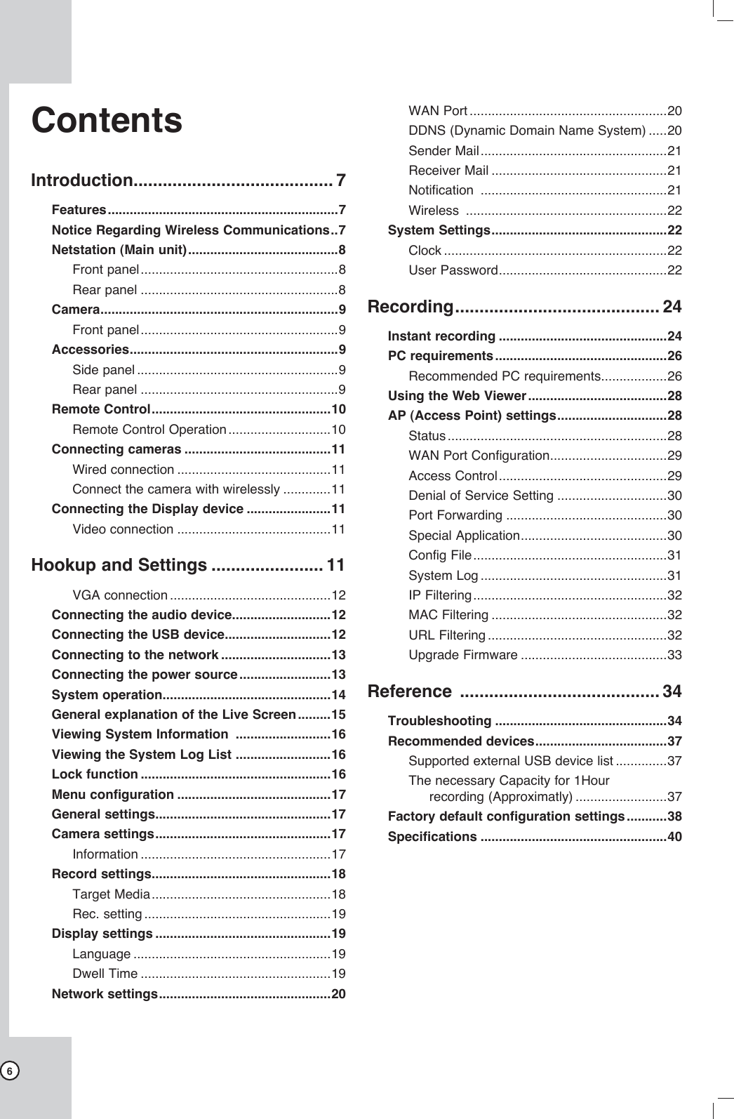
![14System operationAfter the power is inputted for the first time to turn on the unit or set the unit as factory resetting, you will set the initial Administrator password and wireless setup manually.1. Connects the camera(s) to the main unit using the Ethernet cable.2. Connects the main unit to the monitor or display unit and turn them all on.3. When the booting is completed the Password Setup window will be displayed. You can make the user password for this unit.4. Input a new password more than 4-digit numbers and press ENTER. You can enter the password from minimum 4-digit numbers to 8-digit numbers. Enter it again and press ENTER to verity. If you make a mistake before pressing ENTER, press b. 5. Wireless Setup menu is displayed.6. Use V v b B to select the desired setting as shown below.- SSID: You can change the SSID. Set the iden-tifier for the wireless network local in use.- Band: Select the band (2.4GHz (G) or 2.4GHz (B+G).- Channel: Select the channel. (Auto or 1-11(NTSC)/1-13(PAL))- WEP Key: You can set the WEP key to protect a wireless signal between this Netstation and connected camera(s). The WEP key is ran-domly created. 7. Press ENTER while [Apply] option is selected.Update window is displayed and update will start. After update is completed, the Camera Registration menu is displayed.To register the camera(s), see page 17.8. After all settings are completed, press RETURN and select [Yes] then press ENTER to confirm your setting.](https://usermanual.wiki/LG-Electronics-USA/9QK-W1000NS/User-Guide-850873-Page-14.png)
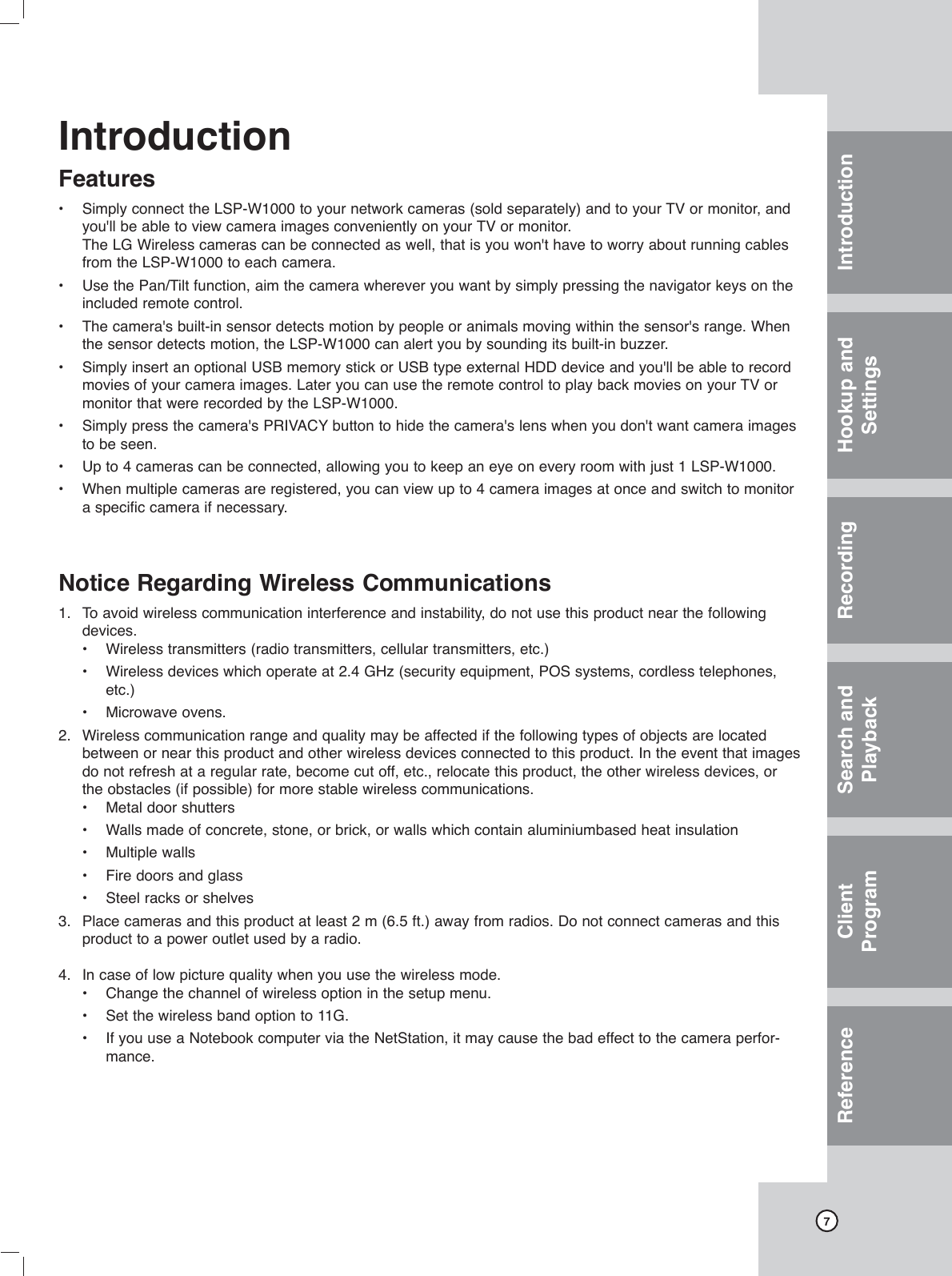
![16Viewing System Information To view system information:1. Press INFO.The system information window is displayed.2. Press ENTER to exit the window.Viewing the System Log List To view the system log list:1. Press LOG.The system information window is displayed.Use b / B to see the previous or next log list.2. Use b / B to select [Close] icon and press ENTER to exit the window.Notes:• The system log list. Camera Channel move, Camera Channel regis-tration, Camera connect, camera disconnect, User (Admin/Normal) Log In, User (Admin/Normal) Log Out, USB Add, USB Format, USB Remove, Rec. Mode change, Network change, Password change, Wireless change, Factory Reset, Write error and Power On. • If you want to erase the system log, select [Clear] and then press ENTER.Lock functionYou can change user type or disable system opera-tion.1. Press LOCK.The login window is displayed.2. Use b / B to select a user type.- Administrator: Unlimited operation of the unit.- Normal User: Use of the limited functions of the system. (Split monitor and live image view are available.)3. Press V and enter the password. You can see the live screen and operate the sys-tem. Note: If you select normal user for the first time, initial pass-word is "0000".](https://usermanual.wiki/LG-Electronics-USA/9QK-W1000NS/User-Guide-850873-Page-16.png)
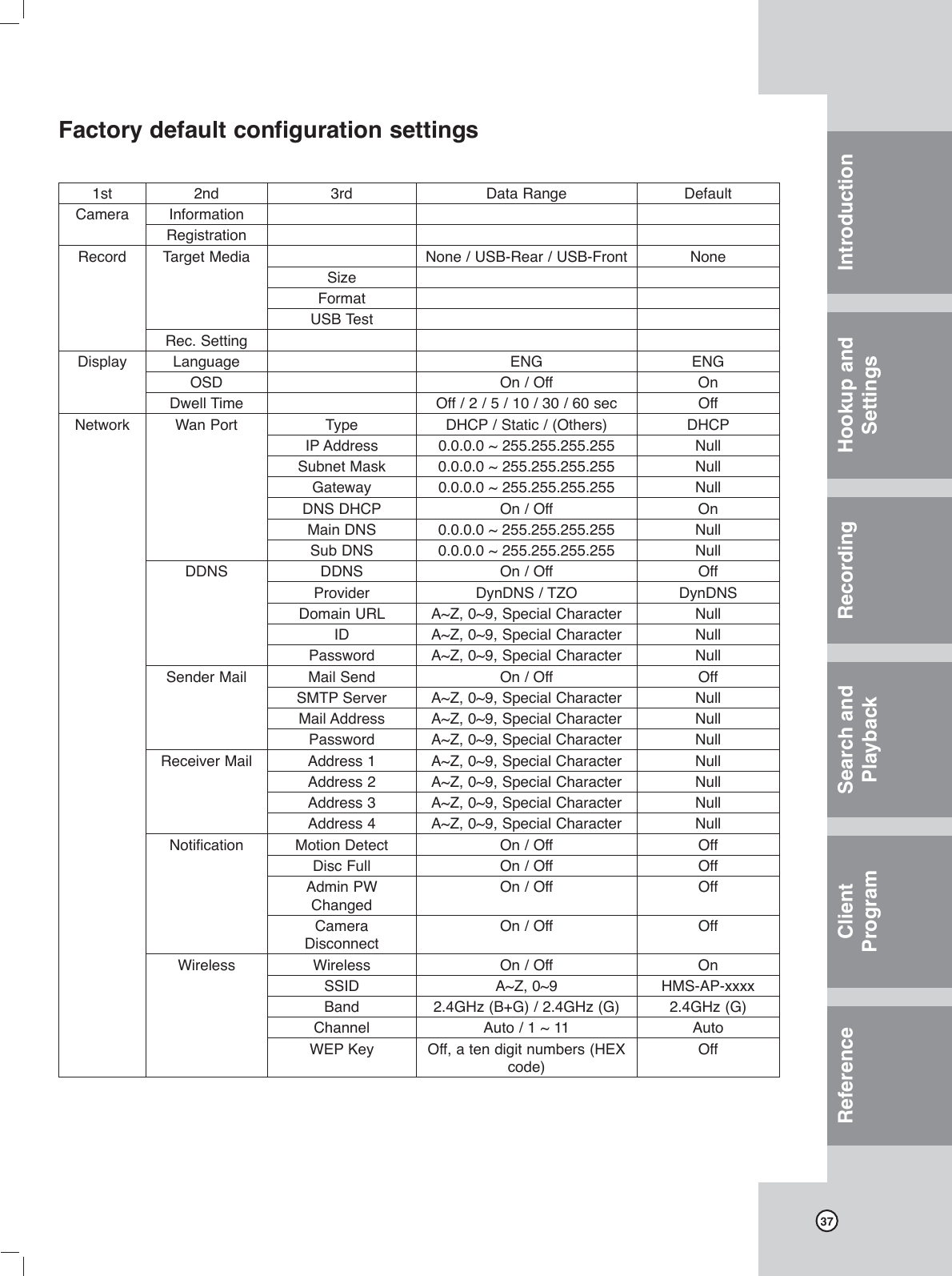
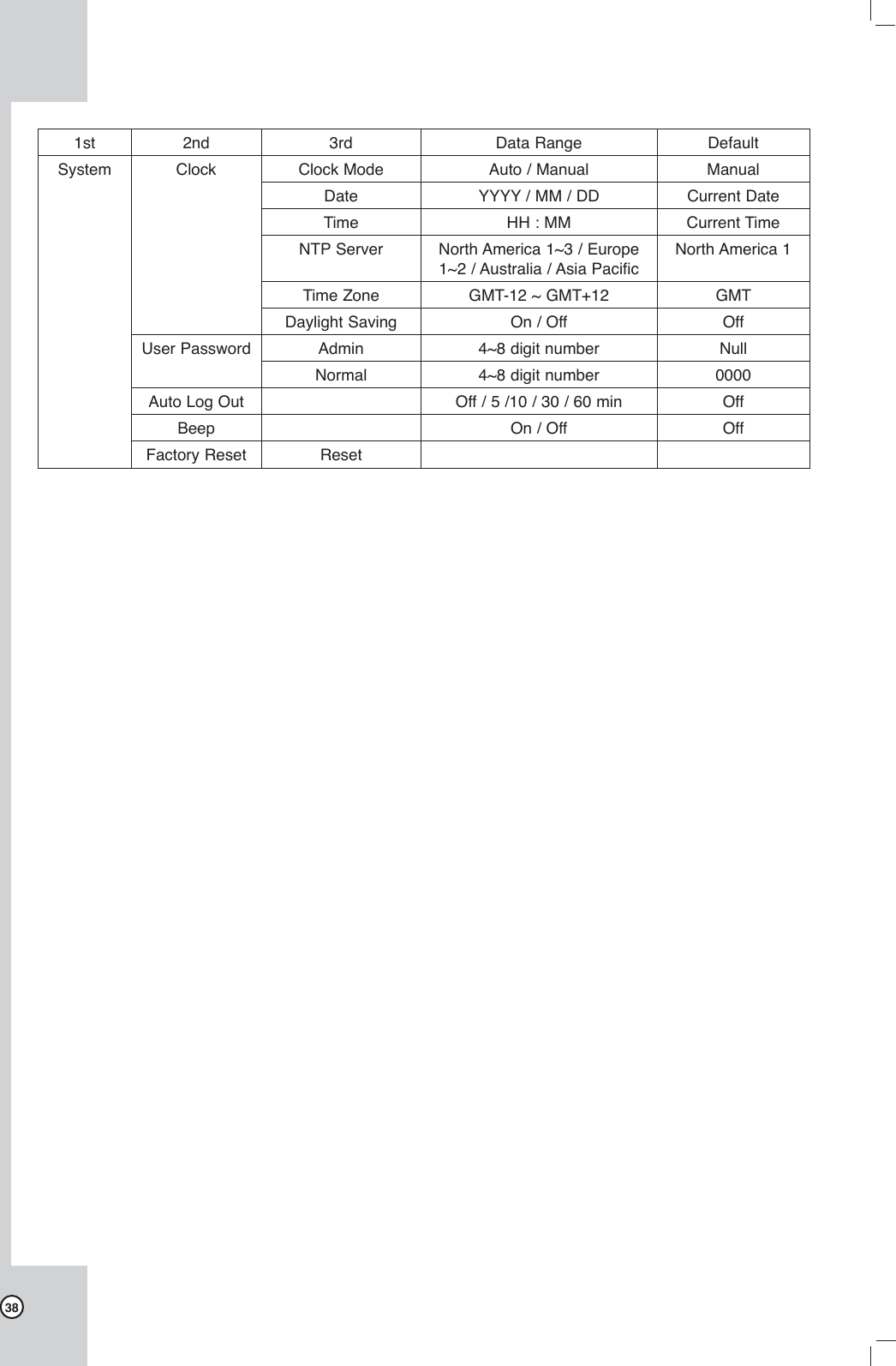
![17IntroductionHookup and SettingsRecordingSearch and PlaybackClient ProgramReferenceMenu configurationThe features and options of this unit are configured through the menu.The operations of this unit can be set via a menu dis-played on the monitor. First levelSecond levelThird levelHelp menuGeneral settingsArrow (v/V/b/B) Buttons:Use these buttons to select the menu options or adjust the options value.ENTER:Select the option or confirm the setting.RETURN:Return to the previous menu or level. Close the displayed windows.1. Press SETUP to display the setup menu.2. Use v / V to select the desired option.3. While the desired item is selected, press B or ENTER move to the second level.4. Use v / V to select the desired option then press B or ENTER to move to the third level or displays selected option windows.5. Use v / V / b / B to select the desired option then press ENTER to set the value.6. Use v / V / b / B to select the desired setting then press ENTER to confirm your selection.7. Press RETURN to exit the setup menu.Note:If you change the option value and then exit the menu or return to the previous menu, the saved message will appears. Then, select [Yes] and press ENTER to save the settings.Camera settingsInformationDisplays registered camera(s) informations.l Ch: Displays the channel number.l Camera Name: Displays the registered camera name.l Preset: Displays the selected preset name in the camera registration menu.l Type: Displays the connected type of the camera.RegistrationYou should register the camera when using it for the first time. You can add, move and erase the camera(s). If you register the camera, the camera should be connected to the Netstation with network cable and you should set the camera mode select switch to Wired position.l CH: Selects the desired channel to register cam-era.l Camera Name: Display the camera name. l Quality: Selects the encording bitrate of MPEG4 encoder in the connected camera. (High, Mid. or Low)](https://usermanual.wiki/LG-Electronics-USA/9QK-W1000NS/User-Guide-850873-Page-17.png)
![20Network settingsWAN Portl Type:- DHCP: DHCP stands for Dynamic Host Configuration Protocol. Network settings of this unit are configured automatically by the DHCP server. If you set to DHCP, the [IP Address], [Subnet Mask] and [Gateway] options are dimmed and these options are not set.- Static: Enter the network settings manually. l IP Address: Enter an IP address using the number buttons (0-9) or Arrow (v/V/b/B) buttons. l Subnet Mask: Enter a subnet mask address using the number buttons (0-9) or Arrow (v/V/b/B) but-tons.l Gateway: Enter the gateway address using the number buttons (0-9) or Arrow (v/V/b/B) buttons.l DNS DHCP: - ON: DNS settings of this unit are configured automatically by the DHCP server.If you set to ON, the [Main DNS] and [Sub DNS], options are dimmed and these options are not set.- OFF: Enter the DNS settings manually. l Main DNS: Enter the Main DNS server address using the number buttons (0-9) or Arrow (v/V/b/B) buttons.l Sub DNS: Enter the Sub DNS server address using the number buttons (0-9) or Arrow (v/V/b/B) buttons.Notes:• For more detail on WAN Port setup, ask your network administrator and/or network service pro-vider.• After change the options, select [Apply] icon and press ENTER to confirm the settings.DDNS (Dynamic Domain Name System)l DDNS- ON: Select to enable DDNS function.This free service is very useful when com-bined with the Virtual Server feature. It allows Internet users to connect to your Virtual Servers using a URL, rather than an IP Address. This also solves the prob-lem of having a dynamic IP address. With a dynamic IP address, your IP address may change whenever you connect, which makes it difficult to connect to you.- OFF: If you set to OFF, the [Provider], [Domain URL], [ID] and [Password] options are dimmed and these options are not set.l Provider: Select the desired DDNS Service Provider from the list (DynDNS or TZO). From the Internet, users will now be able to connect to your Virtual Servers (or DMZ PC) using your Domain URL.l Domain URL: Apply for a Domain URL, and ensure it is allocated to you.l ID: Enter the DDNS registered user ID for the DDNS Service.l Password: Enter the user password in [ID] for the DDNS Service.Notes: • After change the options, select [Apply] icon and press ENTER to confirm the settings.• The DDNS function is serviced using a TCP 8245 port by "No-IP"(http://www.no-ip.com/).In case the unit is used in the network system with a firewall, you have to open the TCP 8245 port so that DDNS data can get into firewall. For more detail on firewall setup, ask your network administrator and/or network service provider.](https://usermanual.wiki/LG-Electronics-USA/9QK-W1000NS/User-Guide-850873-Page-20.png)
![21Sender Maill Mail Send- ON: Select to enable Mail function.- OFF: If you set to OFF, the [SMTP Server], [Mail Address] and [Password] options are dimmed and these options are not set.l SMTP Server: Enter the SMTP Server address. l Mail Address: Enter the mail address.l Password: Enter the password.Notes: • After change the options, select [Apply] icon and press ENTER to confirm the settings. When you press ENTER, the test mail will be sent via the SMTP server to the user mail address automati-cally and the settings are saved when the mail test of the SMTP server is correct.• You should know the SMTP server address of a mail service provider to use the SMTP server. (You should use the port number 25 of the SMTP server for this function.) Receiver Maill Address (1~4): Enter the receiver mail address.You can input up to 4 E-mail addresses.Note: After change the options, select [Apply] icon and press ENTER to confirm the settings.Notification Set the notification options.1. Select item and press ENTER.A checking mark appears in front of the selected option.2. Select [Apply] icon and press ENTER to confirm your settings.l Motion Detection: Sends an E-mail when motion detection has occurred.l USB storage Full: Sends an E-mail when the disc has fully recorded.l Admin PW Change: Sends an E-mail when the administrator password has changed.l Camera Disconnect: Sends an E-mail when a video signal from the camera has stopped because of a cable disconnection or malfunction of a cam-era.Note:For the E-mail sending function, the motion detection has 1 minute term before sending an E-mail again.IntroductionHookup and SettingsRecordingSearch and PlaybackClient ProgramReference](https://usermanual.wiki/LG-Electronics-USA/9QK-W1000NS/User-Guide-850873-Page-21.png)
![22Wireless Set the Wireless options.l Wireless- ON: Select to enable Wireless function. - OFF: Select to unable the Wireless function.l SSID: You can change the SSID. Set the identifier for the wireless network local in use. Do not use the SSID that is the same as the other wireless device.l Band: Select the band (2.4GHz (G) or 2.4GHz (B+G).l Channel: Select the channel. (Auto or 1-11(NTSC)/1-13(PAL)).Use the same channel as that of the other wire-less device, this unit may not be activated nor-mally. In this case, change the channel.l WEP Key: You can set the WEP key to protect a wireless signal between this Netstation and con-nected camera(s). The WEP key is randomly cre-ated. Notes: • After change the options, select [Apply] icon and press ENTER to confirm the settings.• If you change the wireless options in the case of the camera is not connected to the Netstation, the camera(s) may not be activated normally. • If you connect the NetStation and the camera with the wireless network, it may occur the interference with the other wireless device. In that case, refer to the owner's manual of the other wireless device to solve the problem.System SettingsClockl Clock Mode: Select the clock setting mode. Set to [Auto] when using the NTP (Network Time Protocol) server for time adjustment. If the "Clock Mode" is set to [Manual], the time settings should be entered manually and the [NTP Server], [Time Zone] and [Daylight Saving] options are deactivated.l Date: Enter the current date.l Time: Enter the current time.l NTP Server: Select NTP server. You may choose to select NTP server from the pull-down menu.l Time Zone: Select your Time Zone. If your time zone is wrong selected, the E-mail sending time may be displayed in a wrong way. l Daylight Saving: Set to ON to you use the daylight saving function.](https://usermanual.wiki/LG-Electronics-USA/9QK-W1000NS/User-Guide-850873-Page-22.png)
![23User Passwordl Administrator: You can change the password by entering the new password for the administrator. l Normal User: Enter the password for the normal user. Note:Remember the new password. If you forget the new password, reset the unit and then the password and all settings are set to factory default settings .Auto Log OutLogout is automatically at fixed intervals. You can set auto logout time to 5 minutes, 10 minutes, 30 minutes or 60 minutes.Buzzer- ON: Makes a sound when a motion is detected.- OFF: Turns off the motion buzzer.Factory ResetYou can reset the unit to its original factory settings.1. Select [Reset] and press ENTER.2. Use b/B to select [Yes] then press ENTER.The unit will be turned off and on automatically after a few seconds. IntroductionHookup and SettingsRecordingSearch and PlaybackClient ProgramReference](https://usermanual.wiki/LG-Electronics-USA/9QK-W1000NS/User-Guide-850873-Page-23.png)
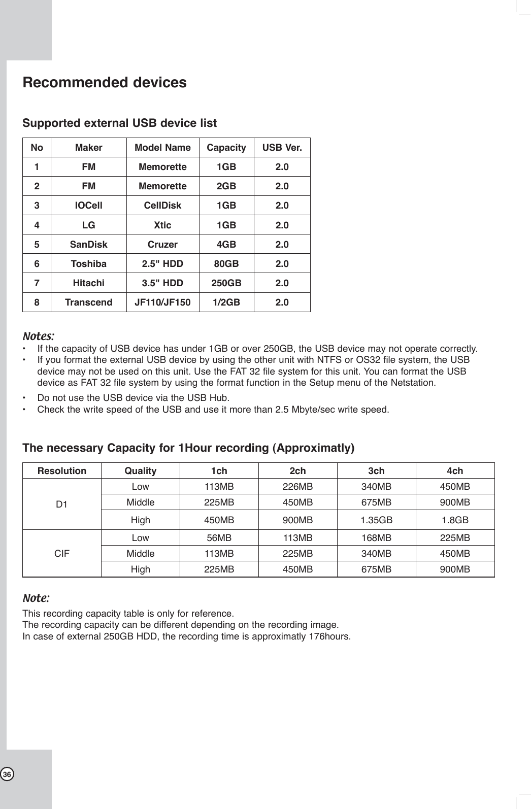
![24RecordingImages from a camera will be recorded on the con-nected USB memory stick or external USB HDD device. Before you start recording, first check the Target media settings in the record menu, and then make the recording target media settings.Instant recordingEnsure all the cameras and USB memory sitck or external USB HDD device are connected and that time and date have been set correctly. 1. Use v/V/b/B to select a live channel you want to record.2. Press the REC button. The RECORD indicator of the unit turns red and the recording type indicator is displayed on the selected channel screen.3. Press the STOP button you want to stop record-ing. If the motion or continuous recording is set, the recording mode will be changed into the motion or continuous recording mode.Note:A USB memory stick or external USB HDD device must be connected in the main unit in order to record camera images.Motion recordingImages are recorded only when the specified cam-era's sensor is activated.1. Press SETUP to display setup menu.2. Use v/V/b/B to select [Rec. Setting] option.The Recording mode setting menu is displayed.3. Press ENTER and use v/V to select the [Motion] option then press B.4. Use v/V to select post time and press ENTER.5. Press RETURN and use b/B to select [Yes] then press ENTER. Motion recording is now set.Continuous recordingImages are recorded continuously.1. Follow steps 1-2 as shown "Motion Recording".3. Press ENTER and use v/V to select the [Continuous] option.4. Press ENTER.5. Press RETURN and use b/B to select [Yes] then press ENTER.Notes:• If you press REC during the motion or continuous recording, the recording mode will be changed into the instant recording mode.• The recorded data file name is made automati-cally as the [Channel name_export date and time] type. • If you set the Day Light Saving option to On and start recording, the word "S" is added on the end of the file name to avoid the repetition of the recorded file name.• Do not remove the USB memory stick or external USB HDD device while the recording is in prog-ress, it may cause a malfunction and the recorded data is not played. • If the recored data time is shorter than 1 second, it will be delected automatically to prevent waste of space. You should record longer than 1 second to save the recorded data.• Do not use the USB memory stick or exter-nal USB HDD device that is used by the other NetStation or it may cause malfunction. • You can record instantly the scheduled channels even though motion or continuous recording is set to the channels. • The video signal of recorded data is saved by the MPEG 4 compression technology. The audio sig-nal of recorded data is saved by the G.726 com-pression technology.• You can not record in following conditions.- The USB memory sitck or external USB HDD device is not attached.- A HDD of external USB HDD device is not for-matted.- The channel has no video input for display.- The USB memory sitck or external USB HDD device has not free space.• You can not record the Motion recording in follow-ing conditions.- The USB memory sitck or external USB HDD device is not attached.- A HDD of external USB HDD device is not for-matted.- The channel has no video input for display.- The Motion recording is not set.• Priority of record.Instant record > Motion record or Continuous record.• If you press SETUP during the recording, the record setting menu is displayed.• You can not record the data for less than 1 sec-onds.](https://usermanual.wiki/LG-Electronics-USA/9QK-W1000NS/User-Guide-850873-Page-24.png)
![25Search the recorded dataWhen the SEARCH button is pressed, the search menu is displayed.1. Use v/V to select the desired source device then press ENTER. If the USB device is not connected, the source name is dimmed and it is not selectable.- USB Front: Select when the USB device is connected to front of unit. Plays back or searches recorded contents of the connected USB device.- USB Rear: Select when the USB device is connected to rear of unit. Plays back or searches recorded contents of the connected USB device.2. Use v/V to select channel to search the recorded contents of the channel.3. Press ENTER. The date seach menu is displayed.4. Select the year, month or date to start search of the recorded data.5. Use b/B to Select the [Get List] icon then press ENTER.The search result is displayed.6. Select the recorded contents you want to play-back.- b/B: Move to previous page or next page.- v/V: Use this buttons to select the recorded contents.- 1~7 number buttons: You can directly select the contents. For example; If you press num-ber 3 button, the select bar moves to the third cloum directly.7. Press ENTER to start playback.The picture is displayed.Note:Do not remove the external USB device while the search is in progress from the unit. It may cause a malfunction. Functions available during playbackButton Functionx STOP Stop playback. [[ PAUSE Pause playback.m/M Press repeatedly to select the required scan speed. (M, MB, MM, MMB or m, mb, mm, mmb)While the playback is paused, press M to play in slow motion. The slow motion playback in reverse is not available.During playback, press m/M for longer than 1 second to go to the next/previous recorded data.bB PLAY Press to play reverse or normal playback.OSD Press to see the reamin time of the playback files. Notes:• If you play the recorded data in the personal com-puter or the other playable unit, MPEG 4 codec and G.726 codec is needed.• You should play the recorded data that is record-ed from the Netstation. If you play the other data that is recorded from the other unit, the Netstation may malfunction.• If you remove the USB device during the search or playback, it stops the search or playback and returns to the live screen.Search and playbackIntroductionHookup and SettingsRecordingSearch and PlaybackClient ProgramReference](https://usermanual.wiki/LG-Electronics-USA/9QK-W1000NS/User-Guide-850873-Page-25.png)
![26Client programClient Program is the network program of the Netstation. The description pictures may differ from your OS (Operating System) type. The pictures used in this manual are based on Windows XP.PC requirementsx OS (Operating System): Windows XP.x CPU: Intel Pentium IV 1GHz or above.x RAM: 256 MB or above.x Graphics Card: AGP VGA with 64 MB Video RAM or above.x Browser: Internet Explorer 6.0.x Etc.: HTML V4.0 or later, JavaScript V1.2 or later.Recommended PC requirements• OS: Windows XP• CPU: Intel Pentium IV• RAM: 512 MB• Graphics Card: AGP VGA with 128 MB Video RAMNotes:• Your Browser must support JavaScript.• If you use the Windows Vista, Windows 2000 or Windows 98, some function may not operate cor-rectly.• If you can not install the client program, check the security settings on your computer. It has limita-tion as depending the security settings. Logging in to the Web Viewer when the computer and the Netstation are directly connect-ed1. Connect a computer to the LAN port of the Netstation using the network cable. 2. Turn on the computer and Netstation.3. Set the network configuration of the computer as shown below.1) Open the [Local Area Connection Properties] windows.2) Select the [Internet Protocol [TCP/IP]] and click [Properties].3) Select the [Obtain an IP address automati-cally] to use DHCP.4) Click [OK] or [Close] repeatedly to save the settings.](https://usermanual.wiki/LG-Electronics-USA/9QK-W1000NS/User-Guide-850873-Page-26.png)
![274. Start the web browser on the computer.5. In the Address Box, enter "http://192.168.1.111".6. Press ENTER and then the login page will be dis-played. Notes:• The login page needs more time to display it according to a network condition.• If the login page is not displayed, check the TCP/IP settings of the computer or the pop-up blocker. If you set the pop-up blocker, the login page is not displayed. You must allow the pop-ups.• If you connect the Netstation for the first time, the Security Warning window is displayed to install the VLC player. You must install the VLC player for using the Web Viewer. • If you block the ActiveX, you can not install the VLC player. In that case, change the "Download unsigned ActiveX controls" option to "Prompt" in the Security Settings menu (Tools > Internet Options... > Security tab > Custom Level... > ActiveX controls and plug-ins) of the browser. • You can install the VLC player manually, visit the "http://www.videolan.org" website and download the VLC player for windows.7. Select the User ID and enter the Password of selected user ID. If you login the Netstation as Administrator, you can not login using the web viewer program.8. Click the [Login]. The Web viewer is displayed.Note:The Web viewer is used only for one user.Logging in to the Web Viewer when the Computer and the Netstation are connected via internet1. Connect a computer to the Internet.2. Connect the internet cable to the WAN port of the Netstation. Note:Ensure that your computer and the Netstation are on the same network segment.3. Turn on the computer and Netstation.4. Check the IP Address of the Netstation. (See page ??)5. Start the web browser on the computer.6. In the Address Box, enter "http://" and the IP Address of the Netstation.Note:If you connect the Netstation to the Router, you should set the Port Forwarding and use the IP address of the Router to enter the web viewer. Refer to the owner's manual of the Router for port forwarding settings.7. Follow steps 6-8 as shown [Logging in to the Web Viewer when the Computer and the Netstation is directly connected].IntroductionHookup and SettingsRecordingSearch and PlaybackClient ProgramReference](https://usermanual.wiki/LG-Electronics-USA/9QK-W1000NS/User-Guide-850873-Page-27.png)
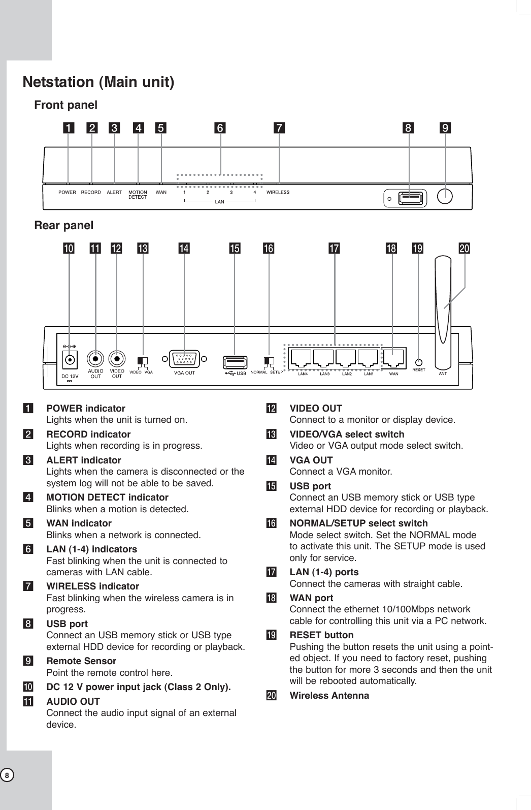
![28Using the Web ViewerYou can control the live image using the Web Viewer.ab cdefg hijia Camera Status Table Shows the camera status.b Camera channel buttons Press the ch1 to ch4 channel button to see the current surveillance images.c Live screen Displays the current surveillance live screend AP setup button Click to go to the AP Setup menu. This button is displayed only when a computer and the Netstation are directly connected using the network cabel.e Log out button Click to go to the log-in page of the Web viewer.f Display the current date and timeg Display the current log-in User ID.h The 4-direction arrow buttons You can pan and tilt the camera using the 4-direc-tion arrow buttons.i Zooming buttons You can operate the zoom range.j Displays the current zoom level.Note:The d, h-j function is used for Administrator.AP (Access Point) settingsAn access point is a bridging device for connecting a wired and wireless network together. Access points are typically wireless routers or stand-alone devices that plug into an Ethernet hub, switch, or router. Wireless adapters should be set to Infrastructure Mode when connecting to an access point or wireless router. (Infrastructure: An 802.11 network in which wireless devices communicate with each other by first going through an Access Point (AP) or wireless router.If you want to change the AP options, refer to the fol-lowing settings.Click [AP] button and then display the Wireless Router setup window.WarningIf you change the AP settings without technical knowl-edge, the Netstation may not be activated. StatusInternet: Shows the internet connection sta-tus.Connection Details: Click to show more details of the internet connection.LAN: Shows the Local area network infor-mation.System: Briefly shows the device name and firmware information.System Data: Click to show the detailed informa-tion of the system.Refresh Screen: Click to refresh all the data.](https://usermanual.wiki/LG-Electronics-USA/9QK-W1000NS/User-Guide-850873-Page-28.png)
![35Symptoms ResolutionsAn E-mail sent from this prod-uct was not received.E-mail reception failed without SMTP server setting.• Make sure the network is correctly set.• Make sure the mail address is input correctly.• Check the spam mail setting of the inputted mail address.(If you set the spam mail, some mails are deleted automatically or classified in the spam mail box)• Some of SMTP mail services do not support an E-mails from private SMTP servers. In this case use the public SMTP server.E-mail reception failed even if the SMTP server was set.• When the [Please check the SMTP information or internet cable] message is displayed.- Check the SMTP server address.- Check the SMTP port number. (Default setting is 25).- Check the network settings.• When the [Please check the authentication information] message is displayed.- Check the user name.- Check the password.• The mail reception failed without error message.- Check the receiver’s mail address.- Check your E-mail is not classified as a spam mail on the receiver's mail set-ting.The remote control does not work properly.Check the batteries in the remote control.Note:If you observe any of the following symptoms:• Some of the front panel LEDs do not light.• The NetStation does not operate normally.You can reboot the NetStation as follows:• Turn off the NetStation and turn it on again after a few seconds.When the recorder does not work normally after rebooting, contact the service center.IntroductionHookup and SettingsRecordingSearch and PlaybackClient ProgramReference](https://usermanual.wiki/LG-Electronics-USA/9QK-W1000NS/User-Guide-850873-Page-35.png)