LG Electronics USA 9QK-W1000NS Home Monitoring System User Manual LSP W1000 ENG wwide 0919 indd
LG Electronics USA Home Monitoring System LSP W1000 ENG wwide 0919 indd
Manual

LSP-W1000_EVNT_ENG
Before connecting, operating or adjusting this product,
please read this owner’s manual carefully and completely.
Home Monitoring
System
Owner’s Manual
MODEL: LSP-W1000
- LSP-W1000NS
- LSP-W1000PS
- LSP-W1000AC
2
This lightning flash with arrowhead symbol
within an equilateral triangle is intended to
alert the user to the presence of uninsulat-
ed dangerous voltage within the product’s
enclosure that may be of sufficient magni-
tude to constitute a risk of electric shock to
persons.
The exclamation point within an equilateral
triangle is intended to alert the user to the
presence of important operating and main-
tenance (servicing) instructions in the litera-
ture accompanying the product.
FCC WARNING: This equipment may generate or
use radio frequency energy. Changes or modifica-
tions to this equipment may cause harmful interfer-
ence unless the modifications are expressly approved
in the instruction manual. The user could lose the
authority to operate this equipment if an unauthorized
change or modification is made.
REGULATORY INFORMATION: FCC Part 15
This equipment has been tested and found to com-
ply with the limits for a Class B digital device, pursu-
ant to Part 15 of the FCC Rules. These limits are
designed to provide reasonable protection against
harmful interference when the product is operated
in a residential installation. This product generates,
uses, and can radiate radio frequency energy and,
if not installed and used in accordance with the
instruction manual, may cause harmful interference
to radio communications. However, there is no guar-
antee that interference will not occur in a particular
installation. If this product does cause harmful inter-
ference to radio or television reception, which can
be determined by turning the product off and on, the
user is encouraged to try to correct the interference
by one or more of the following measures:
• Reorient or relocate the receiving antenna.
• Increase the separation between the product
and receiver.
• Connect the product into an outlet on a circuit
different from that to which the receiver is con-
nected.
• Consult the dealer or an experienced radio/TV
technician for help.
- Labelling information:
This device complies with Part 15 of the FCC rules.
Operation is subject to the following two conditions:
(1) This device may not cause harmful interference,
and (2) This device must accept any interference
received, including interference that may cause
undesired operation.
- RF Exposure Statement:
The antenna(s) used for this transmitter must be
installed to provide a separation distance of at least
20 cm from all persons and must not be colocated
or operating in conjunction with any antenna or
transmitter other than those contained in this device.
FCC Regulations Part 15 Declaration of
Conformity (DoC)
LG Corporation declares that the equipment
described in this document is within the require-
ments of the Code of Federal Regulations listed
below:
Title 47 Part 15, Subpart B, Class B for a digital
device.
This declaration is based upon the compliance of
the data transceiver to the above standards. LG has
determined that the models listed have been shown
to comply with the applicable technical standards if
no unauthorized change is made in the equipment
and if the equipment is properly maintained and
operated.
Apparatus shall not be exposed to dripping or
splashing and no objects filled with liquids, such as
vases, shall be placed on the apparatus.
Disposal of your old appliance
1. When this crossed-out wheeled bin symbol is
attached to a product it means the product is
covered by the European Directive 2002/96/
EC.
2. All electrical and electronic products should
be disposed of separately from the municipal
waste stream via designated collection facili-
ties appointed by the government or the local
authorities.
3. The correct disposal of your old appliance will
help prevent potential negative consequenc-
es for the environment and human health.
4. For more detailed information about disposal
of your old appliance, please contact your
city office, waste disposal service or the shop
where you purchased the product.
CAUTION: TO REDUCE THE RISK
OF ELECTRIC SHOCK
DO NOT REMOVE COVER (OR BACK)
NO USER-SERVICEABLE PARTS INSIDE
REFER SERVICING TO QUALIFIED SERVICE
PERSONNEL.
CAUTION
RISK OF ELECTRIC SHOCK
DO NOT OPEN

3
Canada Notice
This Class B digital apparatus complies with
Canadian ICES-003, Issue 2, and RSS-210,
Issue 4 (Dec. 2000).
“To prevent radio interference to the licensed service, this
device is intended to be operated indoors and away from
windows to provide maximum shielding. Equipment (or its
transmit antenna) that is installed outdoors is subject to
licensing.”
Cet appareil numérique de la classe B est conforme
à la norme NMB-003, No. 2, et CNR-210, No. 4 (Dec.
2000).
« Pour empêcher que cet appareil cause du brouillage
au service faisant l'objet d'une licence, il doit être
utilisé à l'intérieur et devrait être placé loin des
fenêtres afi n de fournir un écran de blindage maximal.
Si le matériel (ou son antenne d'émission) est installé
à l'extérieur, il doit faire l'objet d'une licence. »
Operation is subject to the following two conditions:
this device may not cause interference, and (2)
this device must accept any interference, including
interference that may cause undesired operation of
the device.
The term “IC:” before the certifi cation/registration
number only signifi es that the Industry Canada
technical specifi cations were met.
This device has been designed to operate with an
antenna having a maximum gain of 2 dB. Antenna
having a higher gain is strictly prohibited per
regulations of Industry Canada. The required antenna
impedance is 50 ohms.
To reduce potential radio interference to other users,
the antenna type and its gain should be so chosen
that the equivalent isotropically radiated power
(EIRP) is not more than that required for successful
communication.
European Union
(1999/5/EC)
Translated Statements of Compliance
[English]
This product follows the provisions of the European
Directive 1999/5/EC.
[Danish]
Dette produkt er i overensstemmelse med det
europæiske direktiv 1999/5/EC
[Dutch]
Dit product is in navolging van de bepalingen van
Europees Directief 1999/5/EC.
[Finnish]
Tämä tuote noudattaa EU-direktiivin 1999/5/EC
määräyksiä.
[French]
Ce produit est conforme aux exigences de la Directive
Européenne 1999/5/EC
[German]
Dieses Produkt entspricht den Bestimmungen der
Europäischen Richtlinie 1999/5/EC
[Greek]
Το προϊόν αυτό πληροί τις προβλέψεις της
Ευρωπαϊκής Οδηγίας 1999/5/ΕC.
[Icelandic]
Þessi vara stenst reglugerð Evrópska Efnahags
Bandalagsins númer 1999/5/EC
[Italian]
Questo prodotto è conforme alla Direttiva Europea
1999/5/EC.
[Norwegian]
Dette produktet er i henhold til bestemmelsene i det
europeiske direktivet 1999/5/EC.
[Portuguese]
Este produto cumpre com as normas da Diretiva
Européia 1999/5/EC.
[Spanish]
Este producto cumple con las normas del Directivo
Europeo 1999/5/EC.
[Swedish]
Denna produkt har tillverkats i enlighet med EG-
direktiv 1999/5/EC.

4
France Notice
For Metropolitan departments 2.400 -2.4835 GHz for
indoor use.
Some areas of France have a restricted frequency
band.
There are few possibilities for outdoor use:
On private property or on the private property of public
persons, use is subject to a preliminary authorization
procedure by the Ministry of Defense, with maximum
authorized power of 100 mW in the 2446.5–2483.5
MHz band.
Use outdoors on public property is not permitted.
In the departments listed below, for the entire 2.4 GHz
band:
Maximum authorized power indoors is 100 mW
Maximum authorized power outdoors is 10 mW
There is partial restriction of the 2.4 GHz band
for outdoor/indoor in part of the 2.4 GHz band,
Departments in which the use of the 2400–2483.5
MHz band is permitted with an EIRP of less than 100
mW indoors and less than 10 mW outdoors:
Italia Notice
Outdoor use is prohibited.
EMC Notice
Products bearing the CE marking comply with
the R&TTE Directive (1999/5/EC), EMC Directive
(2004/108/EC) issued by the Commission of the
European Community. Compliance with these
directives implies conformity to the following
European Norms (in parentheses are the equivalent
international standards and regulations):
• EN 55022 (CISPR 22)—Electromagnetic
Interference
• EN55024 (IEC61000-4-2, 3, 4, 5, 6, 8, 11)—
Electromagnetic Immunity
• EN61000-3-2 (IEC61000-3-2)—Power Line
Harmonics
• EN61000-3-3 (IEC61000-3-3)—Power Line Flicker
• EN 300 328-2—Technical requirements for radio
equipment
• EN 301 489-1, -17—General EMC requirements
for radio equipment

ADDITIONAL
PROGRAM
5
1. Read these instructions. - All these safety and
operating instructions should be read before the
product is operated.
2. Keep these instructions. - The safety, operating
and use instructions should be retained for future
reference.
3. Heed all warnings. - All warnings on the product
and in the operating instructions should be adhered
to.
4. Follow all instructions. - All operating and use
instructions should be followed.
5. Do not use this apparatus near water. - For
example: near a bath tub, wash bowl, kitchen sink,
laundry tub, in a wet basement; or near a swimming
pool; and other areas located near water.
6. Clean only with dry cloth. - Unplug this product
from the wall outlet before cleaning. Do not use
liquid cleaners.
7. Do not block any ventilation openings. Install
in accordance with the manufacturer's instruc-
tions. - Slots and openings in the cabinet are pro-
vided for ventilation and to ensure reliable operation
of the product and to protect it from over-heating.
The openings should never be blocked by placing
the product on a bed, sofa, rug or other similar sur-
face. This product should not be placed in a built-
in installation such as a bookcase or rack unless
proper ventilation is provided or the manufacturer’s
instructions have been adhered to.
8. Do not install near any heat sources such as
radiators, heat registers, stoves, or other appa-
ratus (including amplifiers) that produce heat.
9. Do not defeat the safety purpose of the polar-
ized or grounding-type plug. A polarized plug
has two blades with one wider than the other. A
grounding type plug has two blades and a third
grounding prong. The wide blade or the third
prong are provided for your safety. If the pro-
vided plug does not fit into your outlet, consult
an electrician for replacement of the obsolete
outlet.
10. Protect the power cord from being walked on
or pinched particularly at plugs, convenience
receptacles, and the point where they exit from
the apparatus.
11. Only use attachments/accessories specified
by the manufacturer.
12. Use only with the cart, stand, tripod, bracket,
or table specified by the manufacturer, or sold
with the apparatus. When a cart is used, use
caution when moving the cart/apparatus com-
bination to avoid injury from tip-over.
13. Unplug this apparatus during lightning storms
or when unused for long periods of time.
14. Refer all servicing to qualified service person-
nel. Servicing is required when the apparatus
has been damaged in any way, such as power-
supply cord or plug is damaged, liquid has
been spilled or objects have fallen into the
apparatus, the apparatus has been exposed to
rain or moisture, does not operate normally, or
has been dropped.
IMPORTANT SAFETY INSTRUCTIONS
CAUTION:
PLEASE READ AND OBSERVE ALL WARNINGS AND INSTRUCTIONS IN THIS OWNER’S
MANUAL. AND THOSE MARKED ON THE PRODUCT. RETAIN THIS BOOKLET FOR FUTURE
REFERENCE.
This product has been designed and manufactured to assure personal safety. Improper use can result in elec-
tric shock or fire hazard. The safeguards incorporated in this product will protect you if you observe the follow-
ing procedures for installation, use, and servicing.
This product does not contain any parts that can be repaired by the user.
DO NOT REMOVE THE CABINET COVER, OR YOU MAY BE EXPOSED TO DANGEROUS VOLTAGE.
REFER SERVICING TO QUALIFIED SERVICE PERSONNEL ONLY.

6
Contents
Introduction ......................................... 7
Features ...............................................................7
Notice Regarding Wireless Communications ..7
Netstation (Main unit) .........................................8
Front panel ......................................................8
Rear panel ......................................................8
Camera ................................................................. 9
Front panel ......................................................9
Accessories ......................................................... 9
Side panel .......................................................9
Rear panel ......................................................9
Remote Control .................................................10
Remote Control Operation ............................10
Connecting cameras ........................................11
Wired connection ..........................................11
Connect the camera with wirelessly .............11
Connecting the Display device .......................11
Video connection ..........................................11
Hookup and Settings ....................... 11
VGA connection ............................................12
Connecting the audio device ...........................12
Connecting the USB device .............................12
Connecting to the network ..............................13
Connecting the power source .........................13
System operation ..............................................14
General explanation of the Live Screen .........15
Viewing System Information ..........................16
Viewing the System Log List ..........................16
Lock function ....................................................16
Menu configuration ..........................................17
General settings ................................................17
Camera settings ................................................17
Information ....................................................17
Record settings .................................................18
Target Media .................................................18
Rec. setting ...................................................19
Display settings ................................................19
Language ......................................................19
Dwell Time ....................................................19
Network settings ...............................................20
WAN Port ......................................................20
DDNS (Dynamic Domain Name System) .....20
Sender Mail ...................................................21
Receiver Mail ................................................21
Notification ...................................................21
Wireless .......................................................22
System Settings ................................................22
Clock .............................................................22
User Password ..............................................22
Recording .......................................... 24
Instant recording ..............................................24
PC requirements ...............................................26
Recommended PC requirements ..................26
Using the Web Viewer ......................................28
AP (Access Point) settings ..............................28
Status ............................................................28
WAN Port Configuration ................................29
Access Control ..............................................29
Denial of Service Setting ..............................30
Port Forwarding ............................................30
Special Application ........................................30
Config File .....................................................31
System Log ...................................................31
IP Filtering .....................................................32
MAC Filtering ................................................32
URL Filtering .................................................32
Upgrade Firmware ........................................33
Reference ......................................... 34
Troubleshooting ...............................................34
Recommended devices ....................................37
Supported external USB device list ..............37
The necessary Capacity for 1Hour
recording (Approximatly) .........................37
Factory default configuration settings ...........38
Specifications ...................................................40

7
Features
• Simply connect the LSP-W1000 to your network cameras (sold separately) and to your TV or monitor, and
you'll be able to view camera images conveniently on your TV or monitor.
The LG Wireless cameras can be connected as well, that is you won't have to worry about running cables
from the LSP-W1000 to each camera.
• Use the Pan/Tilt function, aim the camera wherever you want by simply pressing the navigator keys on the
included remote control.
• The camera's built-in sensor detects motion by people or animals moving within the sensor's range. When
the sensor detects motion, the LSP-W1000 can alert you by sounding its built-in buzzer.
• Simply insert an optional USB memory stick or USB type external HDD device and you'll be able to record
movies of your camera images. Later you can use the remote control to play back movies on your TV or
monitor that were recorded by the LSP-W1000.
• Simply press the camera's PRIVACY button to hide the camera's lens when you don't want camera images
to be seen.
• Up to 4 cameras can be connected, allowing you to keep an eye on every room with just 1 LSP-W1000.
• When multiple cameras are registered, you can view up to 4 camera images at once and switch to monitor
a specific camera if necessary.
Notice Regarding Wireless Communications
1. To avoid wireless communication interference and instability, do not use this product near the following
devices.
• Wireless transmitters (radio transmitters, cellular transmitters, etc.)
• Wireless devices which operate at 2.4 GHz (security equipment, POS systems, cordless telephones,
etc.)
• Microwave ovens.
2. Wireless communication range and quality may be affected if the following types of objects are located
between or near this product and other wireless devices connected to this product. In the event that images
do not refresh at a regular rate, become cut off, etc., relocate this product, the other wireless devices, or
the obstacles (if possible) for more stable wireless communications.
• Metal door shutters
• Walls made of concrete, stone, or brick, or walls which contain aluminiumbased heat insulation
• Multiple walls
• Fire doors and glass
• Steel racks or shelves
3. Place cameras and this product at least 2 m (6.5 ft.) away from radios. Do not connect cameras and this
product to a power outlet used by a radio.
4. In case of low picture quality when you use the wireless mode.
• Change the channel of wireless option in the setup menu.
• Set the wireless band option to 11G.
• If you use a Notebook computer via the NetStation, it may cause the bad effect to the camera perfor-
mance.
Introduction
IntroductionHookup and
Settings
RecordingSearch and
Playback
Client
Program
Reference
8
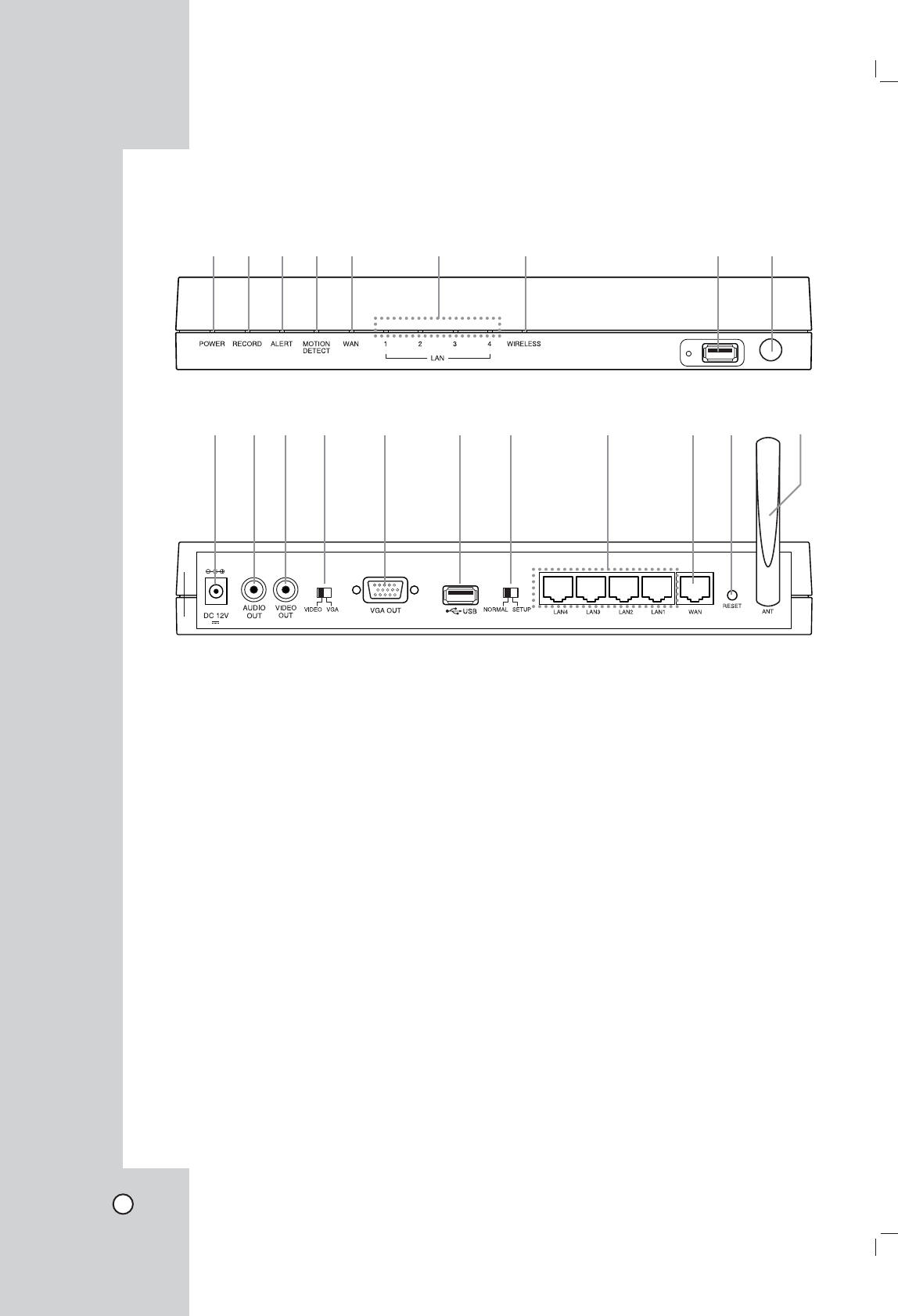
aPOWER indicator
Lights when the unit is turned on.
bRECORD indicator
Lights when recording is in progress.
c ALERT indicator
Lights when the camera is disconnected or the
system log will not be able to be saved.
d MOTION DETECT indicator
Blinks when a motion is detected.
e WAN indicator
Blinks when a network is connected.
f LAN (1-4) indicators
Fast blinking when the unit is connected to
cameras with LAN cable.
g WIRELESS indicator
Fast blinking when the wireless camera is in
progress.
h USB port
Connect an USB memory stick or USB type
external HDD device for recording or playback.
iRemote Sensor
Point the remote control here.
j DC 12 V power input jack (Class 2 Only).
kAUDIO OUT
Connect the audio input signal of an external
device.
lVIDEO OUT
Connect to a monitor or display device.
mVIDEO/VGA select switch
Video or VGA output mode select switch.
nVGA OUT
Connect a VGA monitor.
oUSB port
Connect an USB memory stick or USB type
external HDD device for recording or playback.
pNORMAL/SETUP select switch
Mode select switch. Set the NORMAL mode
to activate this unit. The SETUP mode is used
only for service.
qLAN (1-4) ports
Connect the cameras with straight cable.
r WAN port
Connect the ethernet 10/100Mbps network
cable for controlling this unit via a PC network.
s RESET button
Pushing the button resets the unit using a point-
ed object. If you need to factory reset, pushing
the button for more 3 seconds and then the unit
will be rebooted automatically.
t Wireless Antenna
Netstation (Main unit)
Front panel
abcde f g h i
Rear panel
jklm n o p q rs t
9
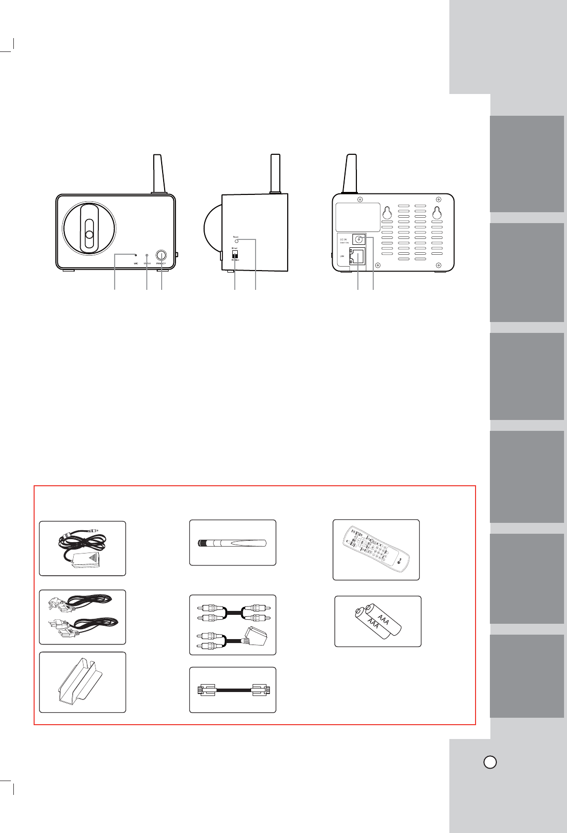
Accessories
AC
adaptor
AC cord
NetStation
Wiress
Antenna
NetStation
Stand
Remote
Control
Lan Cable
AAA Type
Battery
Camera
Front panel Side panel Rear panel
abc de fg
aMIC
The microphone is incorporated into the cam-
era.
bSTATUS indicator
Displays the camera status.
cPRIVACY button
Set the privacy mode, it allows you to make
sure images from the camera cannot be seen.
d Connection mode select switch
Wired or Wireless mode select switch.
e Reset button
Resets camera.
f LAN port
Connects with LAN port of main unit by using
the Straight Cable.
gDC 12V power input jack (Class 2 Only)
Audio/Video
cable
Note: The accessories may be
different depending on models.
IntroductionHookup and
Settings
RecordingSearch and
Playback
Client
Program
Reference
10
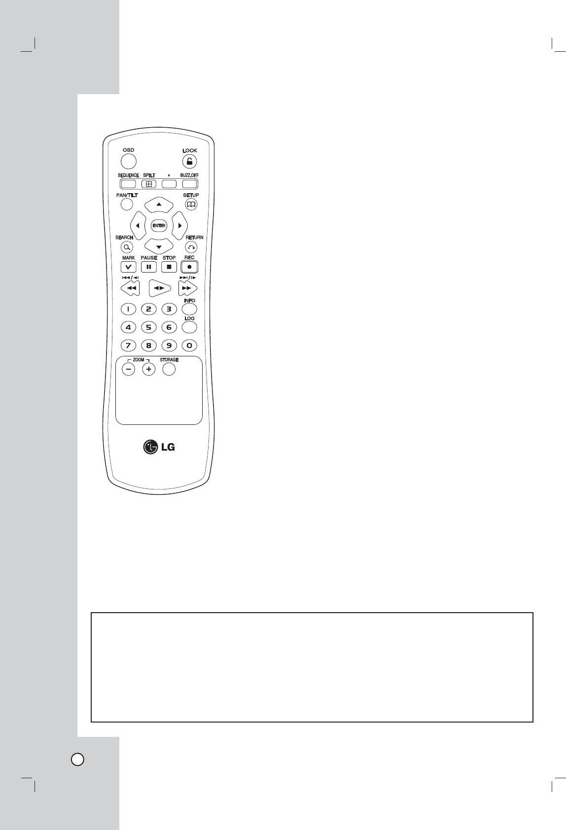
Remote Control OSD
Accesses or removes the On-
screen Display.
LOCK
Displays the lock menu to change
user type or disable system
operation.
SEQUENCE
View all channels in sequence on
the full screen mode.
SPLIT
Displays the screen mode to full
or 4 screens.
BUZZ.OFF
Cancels alarm activation and
returns the system to the condition
before the alarm was activated.
PAN/TILT
Switches the unit to PAN/TILT
mode to control the connected
camera.
SETUP
Displays the setup menu or can-
cels operation of the setup menu.
Arrow Buttons (b B v V)
Selects or moves between the
menu options.
ENTER
Confirms menu selections.
SEARCH
Displays the search menu.
RETURN
Returns to the previous menu or
level.
MARK
Makes the mark point. Use this
button to move the registed cam-
era position.
PAUSE (X)
Pauses playback.
STOP(x)
Stops playback or recording.
REC (z)
Starts recording.
m/c/.
Searches the recorded images
in reverse or skips the recorded
images.
bB
Playback or reverse playback of
recorded images.
M/C/>
Forward searches the recorded
images or skips the recorded
images.
Number Buttons (0,1-9)
Selects a channel directly or use
for network settings.
INFO
Displays the system information
window.
LOG
Displays the System Log List win-
dow.
ZOOM + / -
Zooms in/out on live images.
STORAGE
Displays the Taget Media Space
Information window.
*: This buttons are not available
for this unit.
Remote Control Operation
Point the remote control at the remote sensor and press the buttons.
Cautions:
• Do not mix old and new batteries and never mix different types of batteries such as standard, alkaline, etc.
• Do not put the batteries in the place where young children can reach.
Remote Control Battery installation
Detach the battery cover on the rear of the remote control, and insert two batteries (size AAA) with 3 and #
aligned correctly.
11
Precautions
Be sure to switch off the camera before
installation and connection.
Connecting cameras
Up to 4 cameras can be connected to the Netstation.
You will need to configure the camera registration
settings for cameras connected to the Netstation.
(See page ??).
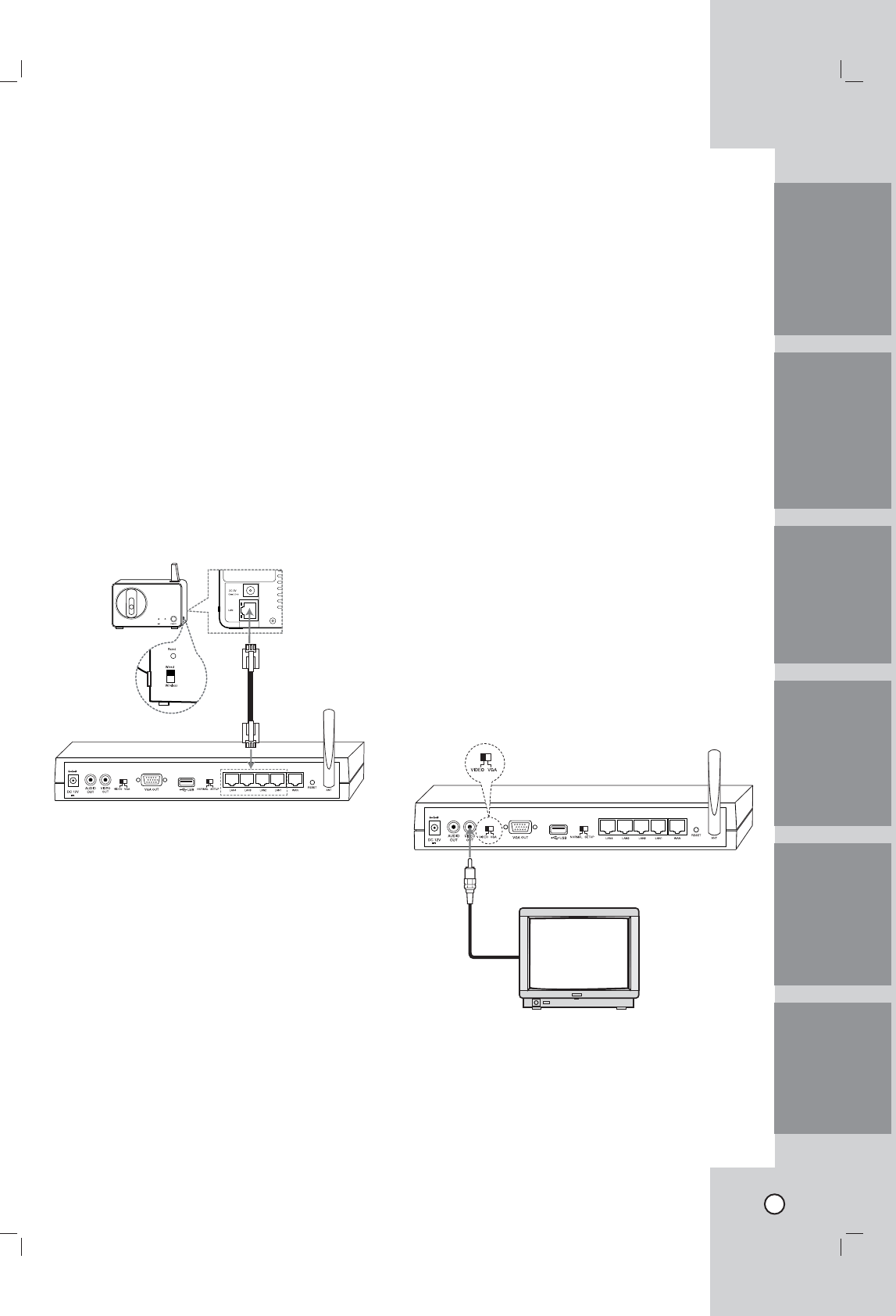
Wired connection
Set the Camera Mode Select switch to Wired posi-
tion. Connect the LAN cabel as shown below. Turn
the Netstation and the camera power on.
The camera will be panning and tilting operation.
Rear of
camera
Notes:
• If the camera is not connected to the Netstation
with LAN cable, the panning and tilting operation
is not be activated even if the camera is powered
on condition.
Before connection, set the camera Connection Mode
Select switch to Wired position.
• If you connect or registrer the camera to the
Netstation using the LAN cable, you should use
the supplied LAN cable or STP cable for shield
the electromagnetic interference.
• The camera(s) is(are) will be used after configur-
ing the camera registration settings. (See page
17).
Connect the camera with wirelessly
If you want to connect without wires, following the
next stpes.
1. Set the camera mode select switch to Wireless
position.
2. Pushing the reset button to reset the camera
using a pointed object.
The camera will be panning and tilting operation.
Note:
The wireless function is possible after configuring the
camera registration settings for cameras connected
to this unit. (See page 17).
Connecting the Display device
Make one of the following connections, depending on
the capabilities of your existing equipment.
Video connection
When using the VIDEO OUT jacks, set the Video
Output mode select switch to VIDEO. Connect the
VIDEO OUT jacks on the rear of the Netstation to the
corresponding input jacks on the TV or monitor using
an VIDEO cable.
Note:
If the OSD is displayed too brightly, the OSD may
be shown like flickering on the monitor. In that case,
adjust the brightness.
Hookup and Settings
IntroductionHookup and
Settings
RecordingSearch and
Playback
Client
Program
Reference
12
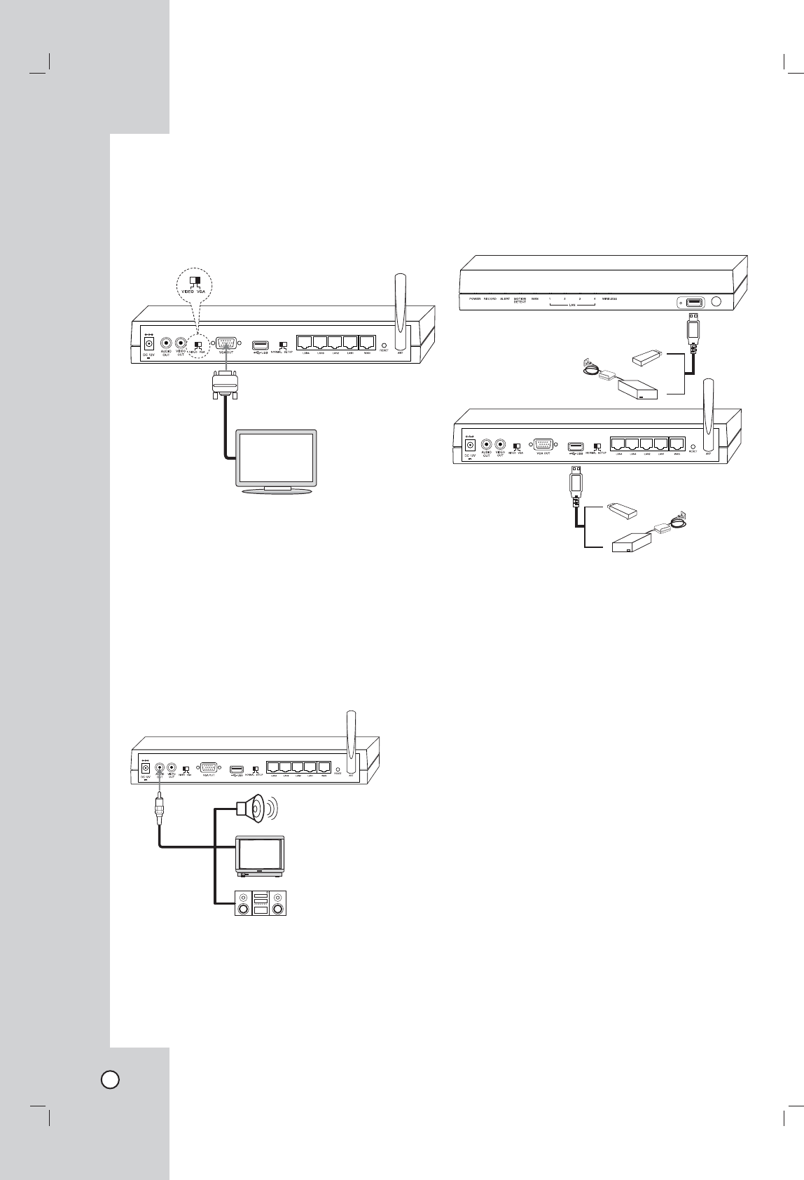
VGA connection
When using the VGA OUT jack, set the Video Output
mode select switch to VGA.
Connect the VGA OUT jacks on the rear of the
NetStation to the corresponding input jacks on the TV
or monitor using an VGA cable.
Note:
If the picture position is unbalanced on the VGA mon-
itor, refer to the owner's manual of the VGA monitor
to adjust the picture position of the VGA monitor.
Connecting the audio device
Connect the AUDIO OUT jacks on the unit to the
mono audio in jacks on your audio deivce.
Connecting the USB device
Connect the USB memory stick or external USB HDD
device for recording or playing. Then, you should use
the recommened USB devices. (see page ??)
13
IntroductionHookup and
Settings
RecordingSearch and
Playback
Client
Program
Reference
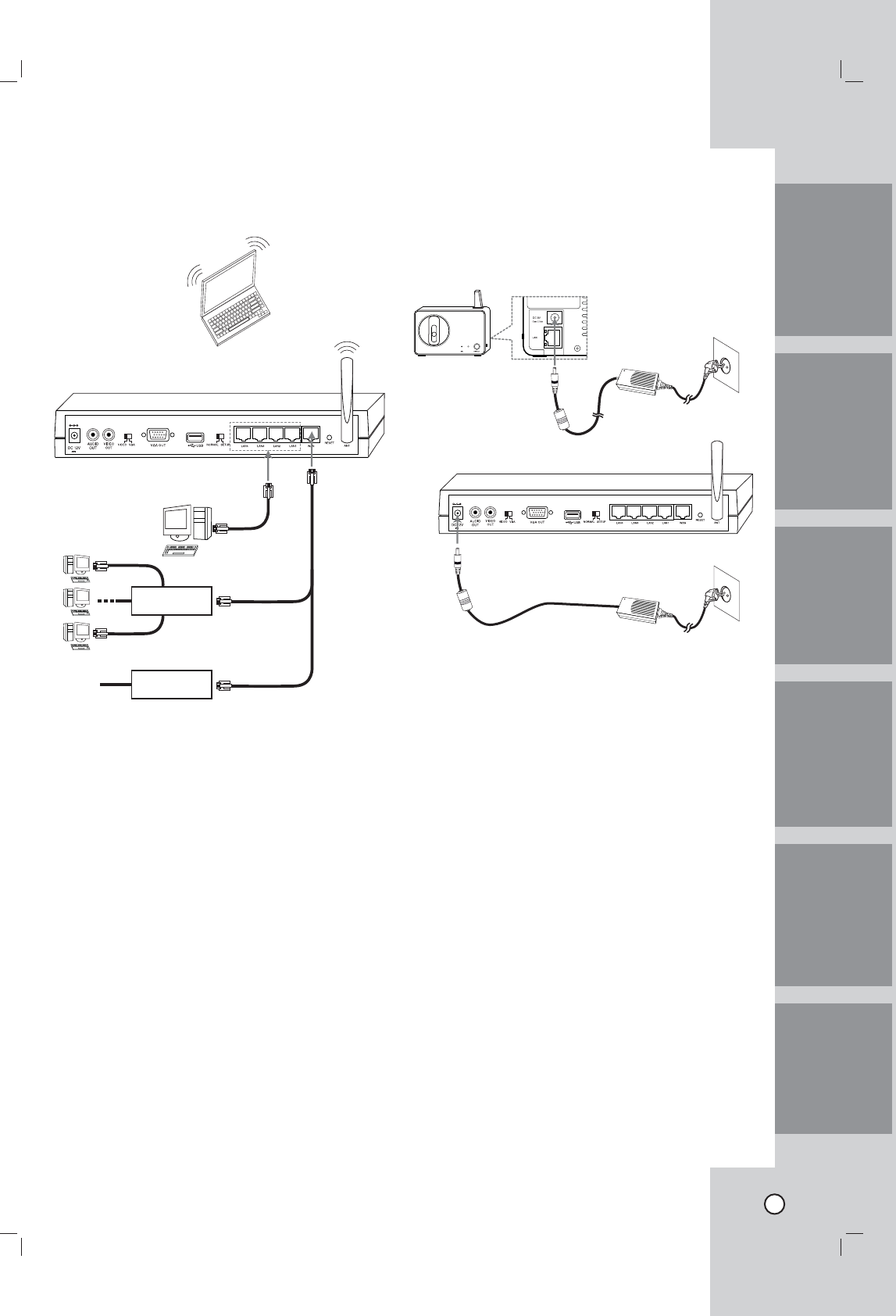
Connecting to the network
Connect the WAN port with a straight ethernet cable.
Router
Modem
Notes:
• If you use the Router, you should set the Port
Forwarding.
• If the IP address of both Netstation and external
Router is same, the Netstation is not operate
normally. In this case, you should change the IP
address of the Router to solve the problem.
Connecting the power source
Connect a DC 12 V power source to the DC 12 V
input terminal as shown below. When camera pow-
ered up, the camera performs a self-check (including
one panning and tilting operation).
Notes:
• Use the supplied adaptor to prevent malfunction.
• The panning and tilting operation activates only
when the camera is connected to the Netstation
with LAN cabel.
14
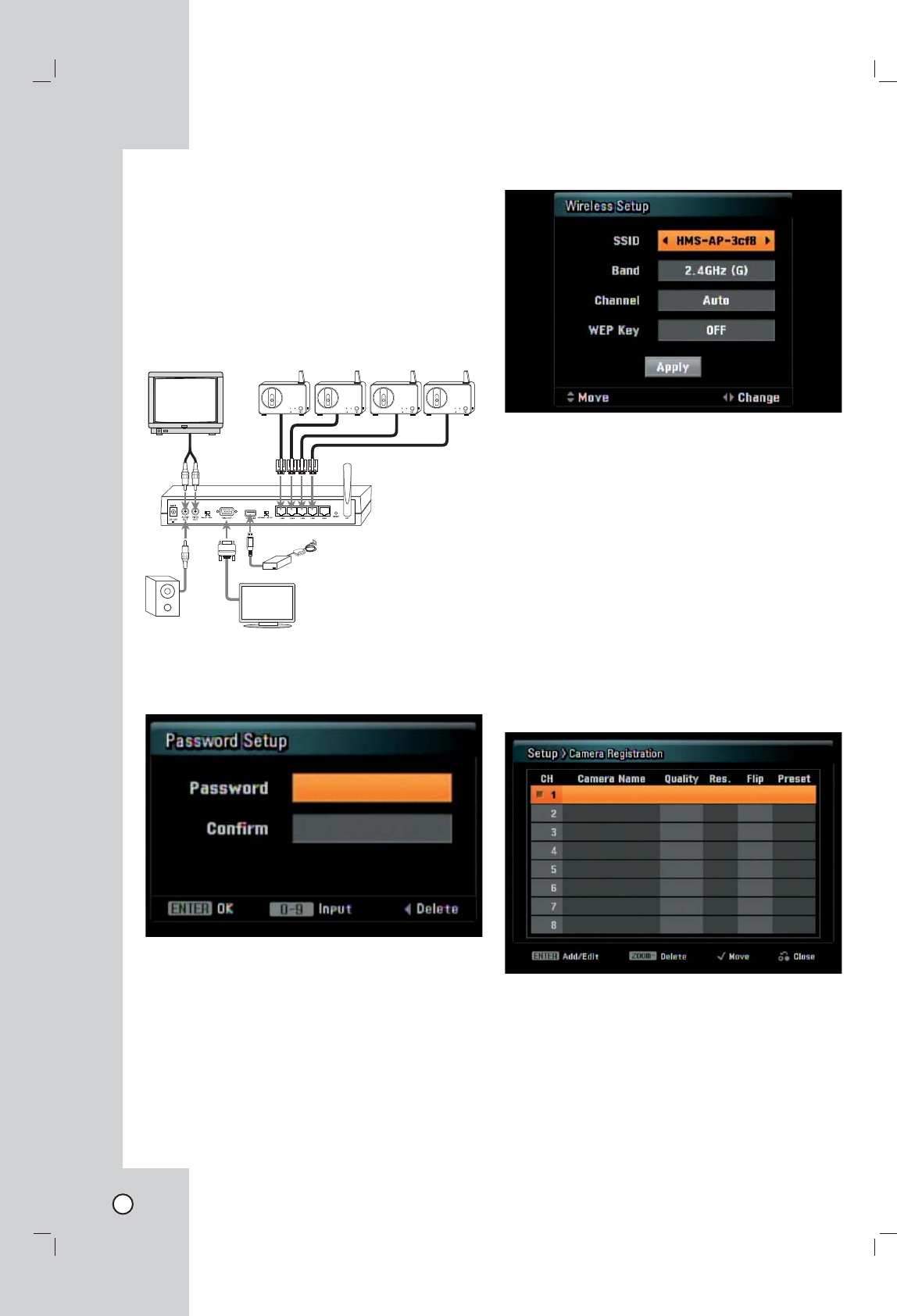
System operation
After the power is inputted for the first time to turn on
the unit or set the unit as factory resetting, you will
set the initial Administrator password and wireless
setup manually.
1. Connects the camera(s) to the main unit using the
Ethernet cable.
2. Connects the main unit to the monitor or display
unit and turn them all on.
3. When the booting is completed the Password
Setup window will be displayed. You can make
the user password for this unit.
4. Input a new password more than 4-digit numbers
and press ENTER. You can enter the password
from minimum 4-digit numbers to 8-digit numbers.
Enter it again and press ENTER to verity. If you
make a mistake before pressing ENTER, press b.
5. Wireless Setup menu is displayed.
6. Use V v b B to select the desired setting as
shown below.
- SSID: You can change the SSID. Set the iden-
tifier for the wireless network local in use.
- Band: Select the band (2.4GHz (G) or 2.4GHz
(B+G).
- Channel: Select the channel. (Auto or 1-
11(NTSC)/1-13(PAL))
- WEP Key: You can set the WEP key to protect
a wireless signal between this Netstation and
connected camera(s). The WEP key is ran-
domly created.
7. Press ENTER while [Apply] option is selected.
Update window is displayed and update will
start. After update is completed, the Camera
Registration menu is displayed.
To register the camera(s), see page 17.
8. After all settings are completed, press RETURN
and select [Yes] then press ENTER to confirm
your setting.
15
IntroductionHookup and
Settings
RecordingSearch and
Playback
Client
Program
Reference
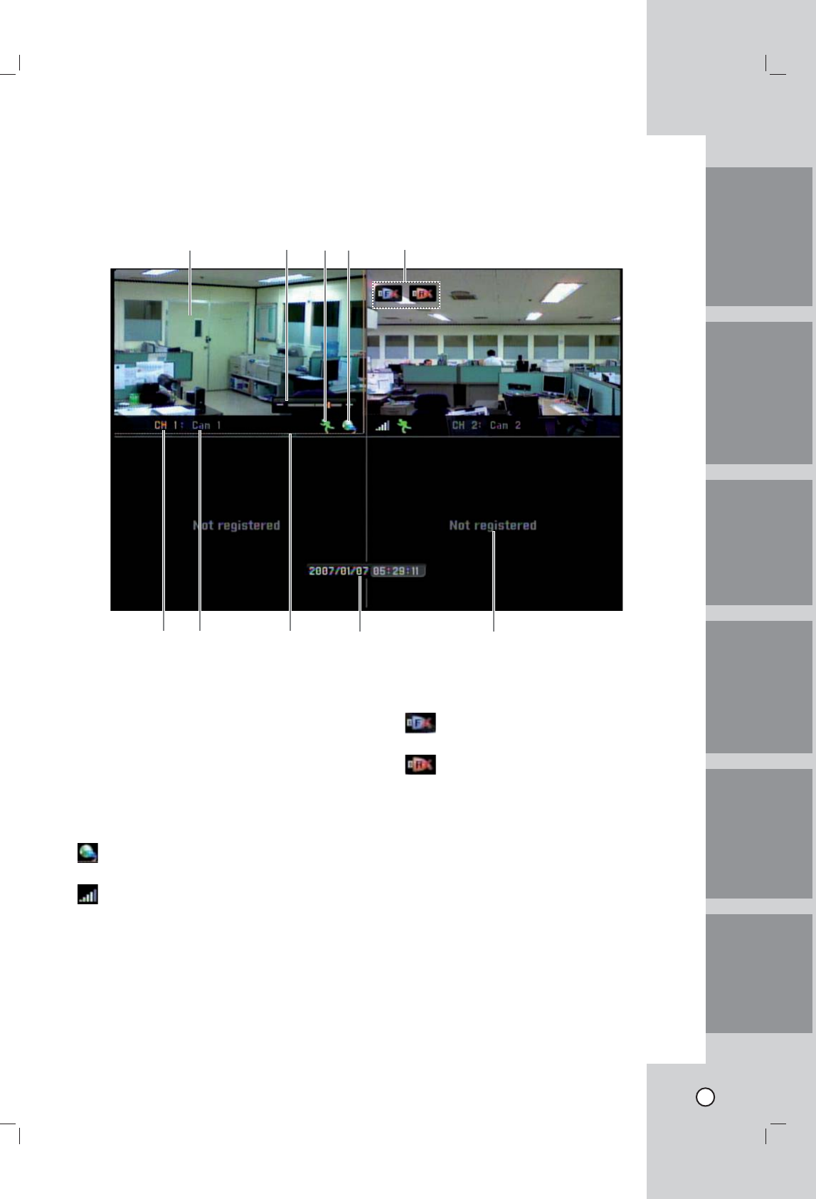
General explanation of the Live
Screen
a Live Screen
Displays the current surveillance live screen.
b Zoom
Displays the current zoom level.
c Status display icon
Displays the icon of detected motions or record-
ing status.
d Connect type with camera
Displays the current connected mode between
the Netstation and the camera.
: Displays when you connect the camera
with wires.
: Displays when you connect the camera in
wireless mode.
eConnected USB device position
Displays the connected USB device position.
: When you connect the USB to the front
of unit.
: When you connect the USB to the rear
of unit.
f Channel Number
Displays the channel number.
g Camera Name
Displays the edited camera name.
h Selected Channel
Displays the selected channel with yellow box.
i Date & Time
Indicates current date and time
j Current status of this channel
Displays when not registered the camera.
abcde
fg h i j
16
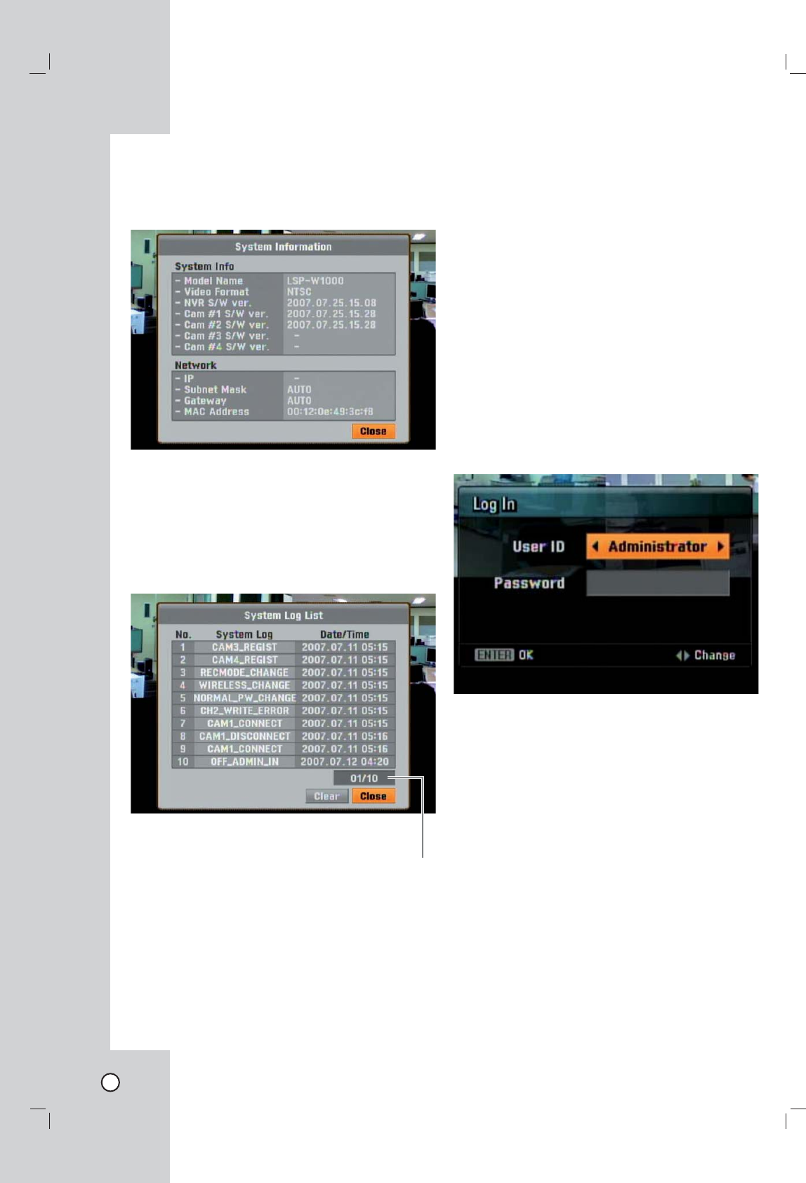
Viewing System Information
To view system information:
1. Press INFO.
The system information window is displayed.
2. Press ENTER to exit the window.
Viewing the System Log List
To view the system log list:
1. Press LOG.
The system information window is displayed.
Use b / B to see the previous
or next log list.
2. Use b / B to select [Close] icon and press
ENTER to exit the window.
Notes:
• The system log list.
Camera Channel move, Camera Channel regis-
tration, Camera connect, camera disconnect, User
(Admin/Normal) Log In, User (Admin/Normal)
Log Out, USB Add, USB Format, USB Remove,
Rec. Mode change, Network change, Password
change, Wireless change, Factory Reset, Write
error and Power On.
• If you want to erase the system log, select [Clear]
and then press ENTER.
Lock function
You can change user type or disable system opera-
tion.
1. Press LOCK.
The login window is displayed.
2. Use b / B to select a user type.
- Administrator: Unlimited operation of the unit.
- Normal User: Use of the limited functions of the
system. (Split monitor and live image view are
available.)
3. Press V and enter the password.
You can see the live screen and operate the sys-
tem.
Note:
If you select normal user for the first time, initial pass-
word is "0000".
17
IntroductionHookup and
Settings
RecordingSearch and
Playback
Client
Program
Reference
Menu configuration
The features and options of this unit are configured
through the menu.
The operations of this unit can be set via a menu dis-
played on the monitor.
First
level
Second
level
Third
level
Help menu
General settings
Arrow (v/V/b/B) Buttons:
Use these buttons to select the menu options or
adjust the options value.
ENTER:
Select the option or confirm the setting.
RETURN:
Return to the previous menu or level.
Close the displayed windows.
1. Press SETUP to display the setup menu.
2. Use v / V to select the desired option.
3. While the desired item is selected, press B or
ENTER move to the second level.
4. Use v / V to select the desired option then press
B or ENTER to move to the third level or displays
selected option windows.
5. Use v / V / b / B to select the desired option
then press ENTER to set the value.
6. Use v / V / b / B to select the desired setting
then press ENTER to confirm your selection.
7. Press RETURN to exit the setup menu.
Note:
If you change the option value and then exit the
menu or return to the previous menu, the saved
message will appears. Then, select [Yes] and press
ENTER to save the settings.
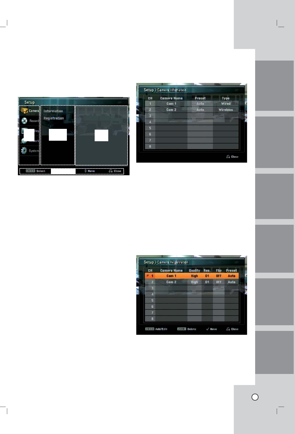
Camera settings
Information
Displays registered camera(s) informations.
l Ch: Displays the channel number.
l Camera Name: Displays the registered camera
name.
l Preset: Displays the selected preset name in the
camera registration menu.
l Type: Displays the connected type of the camera.
Registration
You should register the camera when using it for
the first time. You can add, move and erase the
camera(s). If you register the camera, the camera
should be connected to the Netstation with network
cable and you should set the camera mode select
switch to Wired position.
l CH: Selects the desired channel to register cam-
era.
l Camera Name: Display the camera name.
l Quality: Selects the encording bitrate of MPEG4
encoder in the connected camera. (High, Mid. or
Low)
18
l Res.: Selects the resolution of camera input sig-
nals. (D1: 720x480, CIF: 320x240).
l Flip: Set Flip to ON, when you see the live screen
to filp the picture.
l Preset: Selects the picture quality of video sensor
in the connected camera. (AUTO, P1(Fluorescent),
P2 (Daylight), P3 (Cloudy), P4 (Incandescent) or
P5 (CRT))
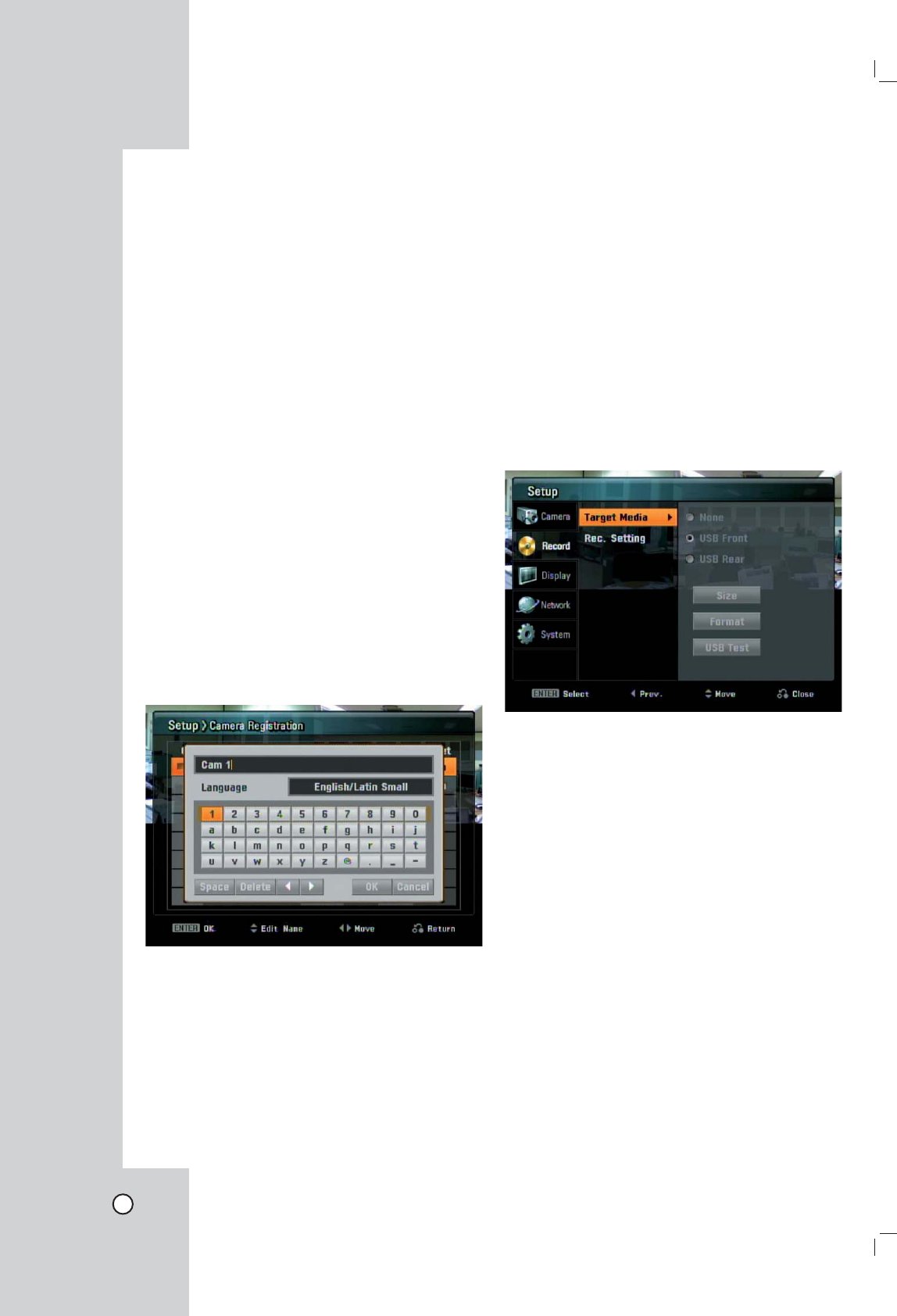
Moving a registered camera channel
1. Select a camera channel and press MARK.
2. Use v / V to choose a new channel to move the
registered camera into the channel, then press
ENTER.
Change the registered camera name
You can change the camera name.
The names can be up to 16 characters long.
1. Choose the camera channel you want to change
the name, then press ENTER.
2. Press v or V to display the character input menu.
3. Enter a new name. Use b / B / v / V to select
a character then press ENTER to confirm your
selection.
Using the character input menu
- Language: Use b / B to change keyboard type.
- Space: Inserts a space at the cursor position.
- Delete: Deletes the previous character at the cur-
sor position.
- b, B: Moves cursor to left or right.
- OK: Select to finish.
- Cancel: Cancels all entered characters.
Tip:
Remote control buttons for entering a
name.
Numbers (0-9): Enters the corresponding character
at the cursor posit ion.
m / M: Moves cursor to left or right.
Record settings
Target Media
Select a media to record. The USB device should be
connected to the NetStation for recording.
l None: No recording.
l USB Front: Selects when you connect the USB
device to the front panel of main unit.
l USB Rear: Selects when you connect the USB
device to the front panel of main unit.
l Size: Displays the free space of the selected USB
device.
l Format: To format the selected USB media.
l USB Test: To test the USB device.
19
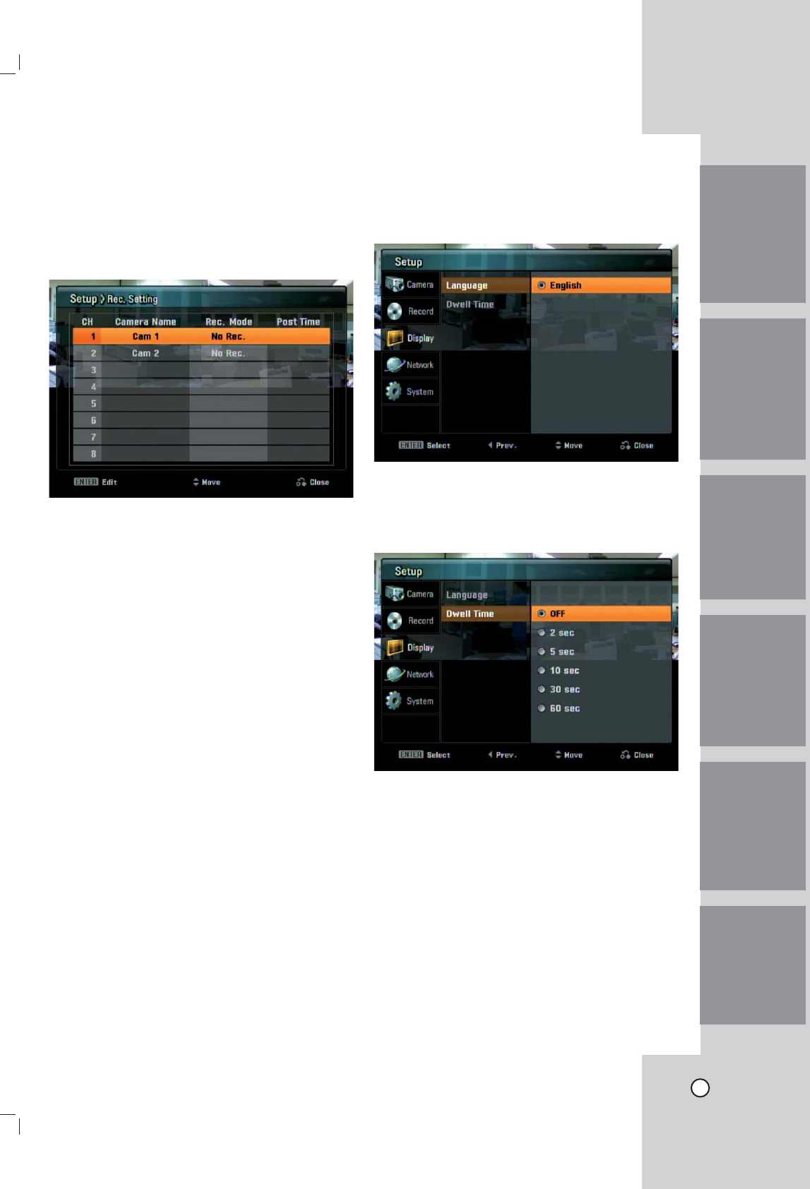
Rec. setting
1. Use v/V to select the camera channel and press
ENTER.
2. Use v/V to select recording mode for selected
camera.
3. Press ENTER to confirm your settings.
l CH: Displays the channel number.
l Camera Name: Display the camera name.
l Rec. Mode: Selects the desired recording option.
- No Rec.: Instant recording is possible using
the REC button of the remote control.
- Motion: Recording starts automatically when
motion is detected.
- Continuous: Continuous recording.
l Post Time: Specify the post-event recording time
that records the situation from when the motion has
been detected. This option is activated when the
Rec. Mode is set the Motion mode.
Display settings
Language
Select a language for the setup menu and informa-
tion display.
Dwell Time
You can set the channel sequence time to 2 seconds,
5 seconds, 10 seconds, 30 seconds or 60 seconds.
IntroductionHookup and
Settings
RecordingSearch and
Playback
Client
Program
Reference
20
Network settings
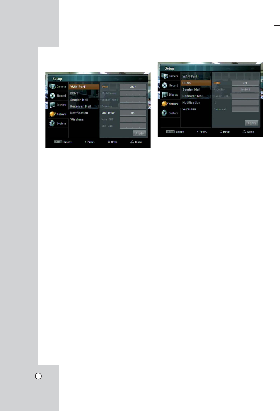
WAN Port
l Type:
- DHCP: DHCP stands for Dynamic Host
Configuration Protocol. Network settings of this
unit are configured automatically by the DHCP
server. If you set to DHCP, the [IP Address],
[Subnet Mask] and [Gateway] options are
dimmed and these options are not set.
- Static: Enter the network settings manually.
l IP Address: Enter an IP address using the number
buttons (0-9) or Arrow (v/V/b/B) buttons.
l Subnet Mask: Enter a subnet mask address using
the number buttons (0-9) or Arrow (v/V/b/B) but-
tons.
l Gateway: Enter the gateway address using the
number buttons (0-9) or Arrow (v/V/b/B) buttons.
l DNS DHCP:
- ON: DNS settings of this unit are configured
automatically by the DHCP server.
If you set to ON, the [Main DNS] and [Sub DNS],
options are dimmed and these options are not set.
- OFF: Enter the DNS settings manually.
l Main DNS: Enter the Main DNS server address
using the number buttons (0-9) or Arrow (v/V/b/
B) buttons.
l Sub DNS: Enter the Sub DNS server address
using the number buttons (0-9) or Arrow (v/V/b/
B) buttons.
Notes:
• For more detail on WAN Port setup, ask your
network administrator and/or network service pro-
vider.
• After change the options, select [Apply] icon and
press ENTER to confirm the settings.
DDNS (Dynamic Domain Name System)
l DDNS
- ON: Select to enable DDNS function.
This free service is very useful when com-
bined with the Virtual Server feature. It
allows Internet users to connect to your
Virtual Servers using a URL, rather than
an IP Address. This also solves the prob-
lem of having a dynamic IP address. With
a dynamic IP address, your IP address
may change whenever you connect, which
makes it difficult to connect to you.
- OFF: If you set to OFF, the [Provider], [Domain
URL], [ID] and [Password] options are
dimmed and these options are not set.
l Provider: Select the desired DDNS Service
Provider from the list (DynDNS or TZO). From the
Internet, users will now be able to connect to your
Virtual Servers (or DMZ PC) using your Domain
URL.
l Domain URL: Apply for a Domain URL, and
ensure it is allocated to you.
l ID: Enter the DDNS registered user ID for the
DDNS Service.
l Password: Enter the user password in [ID] for the
DDNS Service.
Notes:
• After change the options, select [Apply] icon and
press ENTER to confirm the settings.
• The DDNS function is serviced using a TCP 8245
port by "No-IP"(http://www.no-ip.com/).
In case the unit is used in the network system
with a firewall, you have to open the TCP 8245
port so that DDNS data can get into firewall. For
more detail on firewall setup, ask your network
administrator and/or network service provider.
21
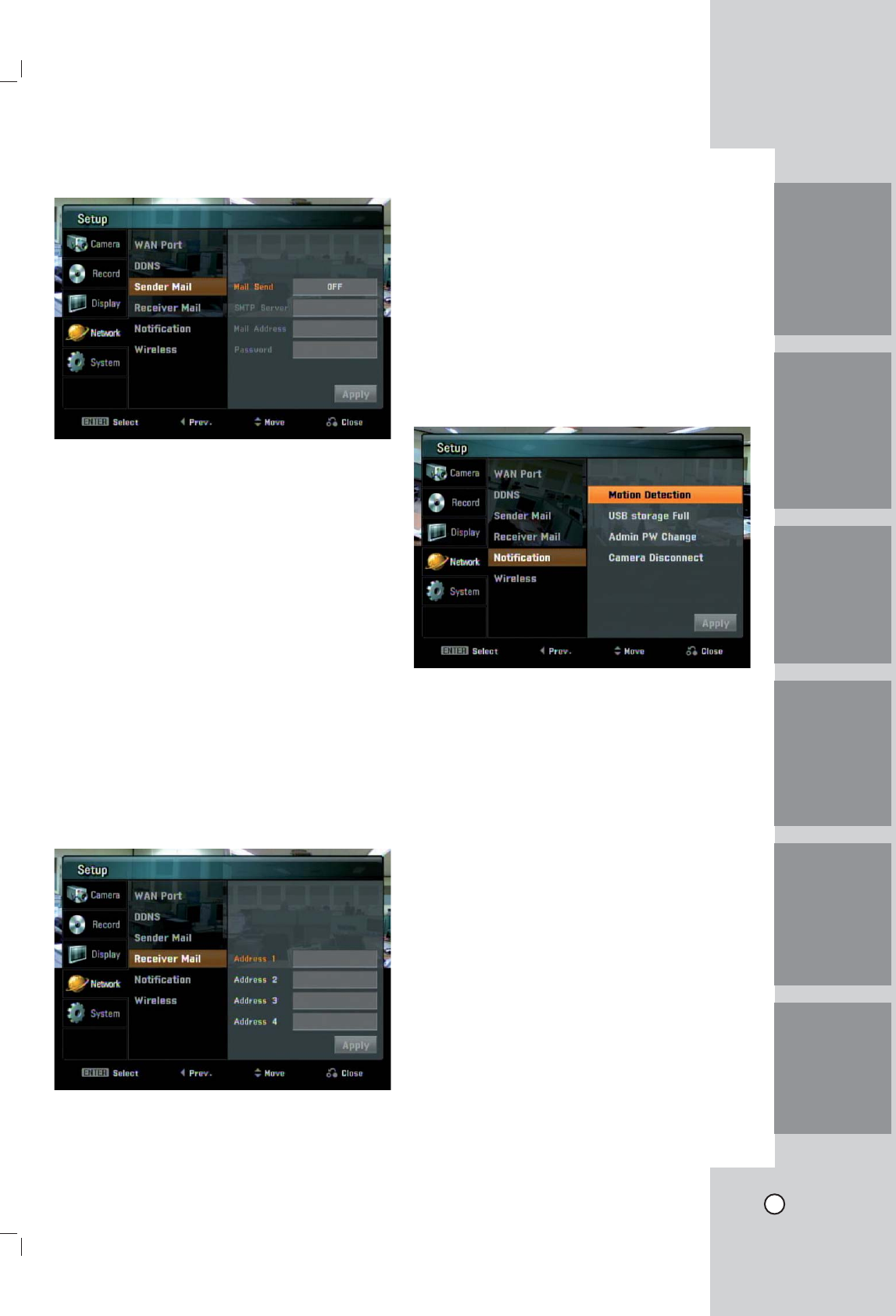
Sender Mail
l Mail Send
- ON: Select to enable Mail function.
- OFF: If you set to OFF, the [SMTP Server], [Mail
Address] and [Password] options are dimmed
and these options are not set.
l SMTP Server: Enter the SMTP Server address.
l Mail Address: Enter the mail address.
l Password: Enter the password.
Notes:
• After change the options, select [Apply] icon and
press ENTER to confirm the settings. When you
press ENTER, the test mail will be sent via the
SMTP server to the user mail address automati-
cally and the settings are saved when the mail
test of the SMTP server is correct.
• You should know the SMTP server address of
a mail service provider to use the SMTP server.
(You should use the port number 25 of the SMTP
server for this function.)
Receiver Mail
l Address (1~4): Enter the receiver mail address.
You can input up to 4 E-mail addresses.
Note:
After change the options, select [Apply] icon and
press ENTER to confirm the settings.
Notification
Set the notification options.
1. Select item and press ENTER.
A checking mark appears in front of the selected
option.
2. Select [Apply] icon and press ENTER to confirm
your settings.
l Motion Detection: Sends an E-mail when motion
detection has occurred.
l USB storage Full: Sends an E-mail when the disc
has fully recorded.
l Admin PW Change: Sends an E-mail when the
administrator password has changed.
l Camera Disconnect: Sends an E-mail when a
video signal from the camera has stopped because
of a cable disconnection or malfunction of a cam-
era.
Note:
For the E-mail sending function, the motion detection
has 1 minute term before sending an E-mail again.
IntroductionHookup and
Settings
RecordingSearch and
Playback
Client
Program
Reference
22
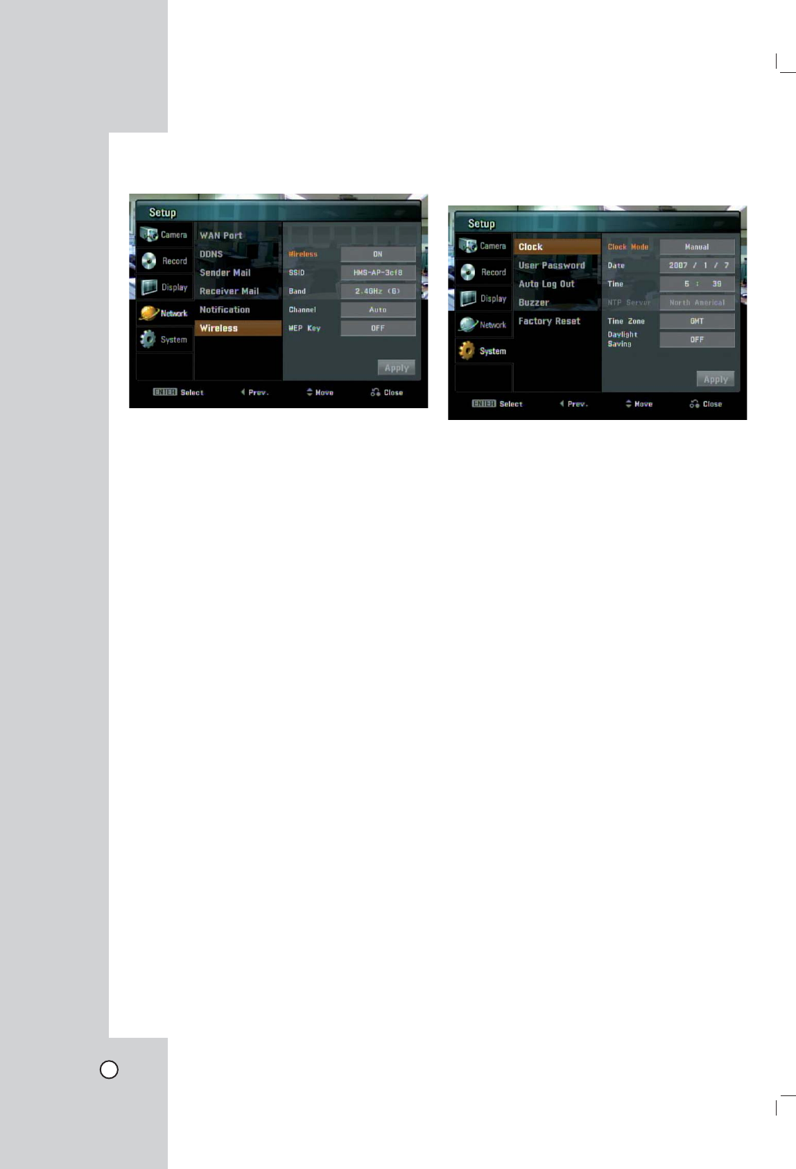
Wireless
Set the Wireless options.
l Wireless
- ON: Select to enable Wireless function.
- OFF: Select to unable the Wireless function.
l SSID: You can change the SSID. Set the identifier
for the wireless network local in use. Do not use
the SSID that is the same as the other wireless
device.
l Band: Select the band (2.4GHz (G) or 2.4GHz
(B+G).
l Channel: Select the channel. (Auto or 1-
11(NTSC)/1-13(PAL)).
Use the same channel as that of the other wire-
less device, this unit may not be activated nor-
mally. In this case, change the channel.
l WEP Key: You can set the WEP key to protect a
wireless signal between this Netstation and con-
nected camera(s). The WEP key is randomly cre-
ated.
Notes:
• After change the options, select [Apply] icon and
press ENTER to confirm the settings.
• If you change the wireless options in the case of
the camera is not connected to the Netstation, the
camera(s) may not be activated normally.
• If you connect the NetStation and the camera with
the wireless network, it may occur the interference
with the other wireless device. In that case, refer
to the owner's manual of the other wireless device
to solve the problem.
System Settings
Clock
l Clock Mode: Select the clock setting mode. Set to
[Auto] when using the NTP (Network Time Protocol)
server for time adjustment. If the "Clock Mode" is
set to [Manual], the time settings should be entered
manually and the [NTP Server], [Time Zone] and
[Daylight Saving] options are deactivated.
l Date: Enter the current date.
l Time: Enter the current time.
l NTP Server: Select NTP server. You may choose
to select NTP server from the pull-down menu.
l Time Zone: Select your Time Zone. If your time
zone is wrong selected, the E-mail sending time
may be displayed in a wrong way.
l Daylight Saving: Set to ON to you use the daylight
saving function.
23
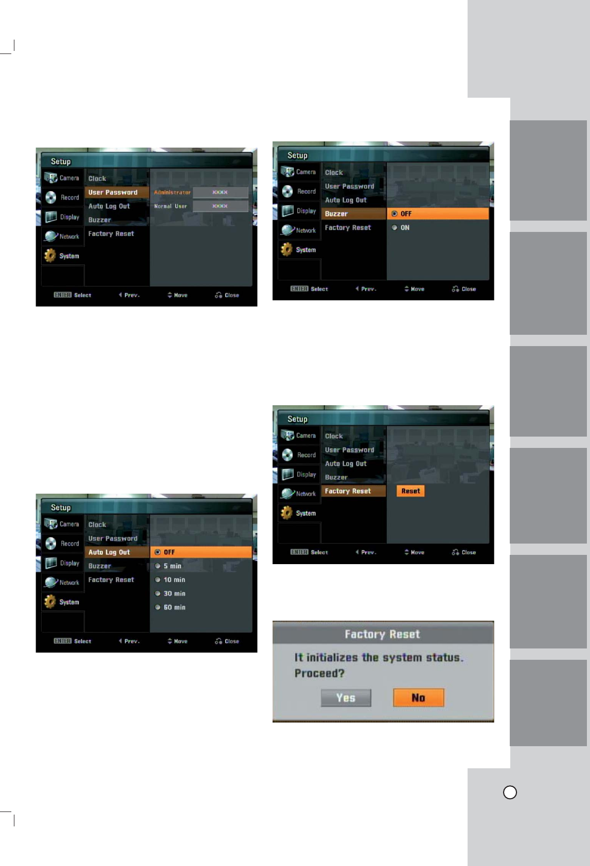
User Password
l Administrator: You can change the password by
entering the new password for the administrator.
l Normal User: Enter the password for the normal
user.
Note:
Remember the new password. If you forget the new
password, reset the unit and then the password and
all settings are set to factory default settings .
Auto Log Out
Logout is automatically at fixed intervals. You can set
auto logout time to 5 minutes, 10 minutes, 30 minutes
or 60 minutes.
Buzzer
- ON: Makes a sound when a motion is detected.
- OFF: Turns off the motion buzzer.
Factory Reset
You can reset the unit to its original factory settings.
1. Select [Reset] and press ENTER.
2. Use b/B to select [Yes] then press ENTER.
The unit will be turned off and on automatically
after a few seconds.
IntroductionHookup and
Settings
RecordingSearch and
Playback
Client
Program
Reference

24
Recording
Images from a camera will be recorded on the con-
nected USB memory stick or external USB HDD
device. Before you start recording, first check the
Target media settings in the record menu, and then
make the recording target media settings.
Instant recording
Ensure all the cameras and USB memory sitck or
external USB HDD device are connected and that
time and date have been set correctly.
1. Use v/V/b/B to select a live channel you want
to record.
2. Press the REC button. The RECORD indicator of
the unit turns red and the recording type indicator
is displayed on the selected channel screen.
3. Press the STOP button you want to stop record-
ing. If the motion or continuous recording is set,
the recording mode will be changed into the
motion or continuous recording mode.
Note:
A USB memory stick or external USB HDD device
must be connected in the main unit in order to record
camera images.
Motion recording
Images are recorded only when the specified cam-
era's sensor is activated.
1. Press SETUP to display setup menu.
2. Use v/V/b/B to select [Rec. Setting] option.
The Recording mode setting menu is displayed.
3. Press ENTER and use v/V to select the [Motion]
option then press B.
4. Use v/V to select post time and press ENTER.
5. Press RETURN and use b/B to select [Yes] then
press ENTER. Motion recording is now set.
Continuous recording
Images are recorded continuously.
1. Follow steps 1-2 as shown "Motion Recording".
3. Press ENTER and use v/V to select the
[Continuous] option.
4. Press ENTER.
5. Press RETURN and use b/B to select [Yes] then
press ENTER.
Notes:
• If you press REC during the motion or continuous
recording, the recording mode will be changed
into the instant recording mode.
• The recorded data file name is made automati-
cally as the [Channel name_export date and time]
type.
• If you set the Day Light Saving option to On and
start recording, the word "S" is added on the
end of the file name to avoid the repetition of the
recorded file name.
• Do not remove the USB memory stick or external
USB HDD device while the recording is in prog-
ress, it may cause a malfunction and the recorded
data is not played.
• If the recored data time is shorter than 1 second,
it will be delected automatically to prevent waste
of space. You should record longer than 1 second
to save the recorded data.
• Do not use the USB memory stick or exter-
nal USB HDD device that is used by the other
NetStation or it may cause malfunction.
• You can record instantly the scheduled channels
even though motion or continuous recording is set
to the channels.
• The video signal of recorded data is saved by the
MPEG 4 compression technology. The audio sig-
nal of recorded data is saved by the G.726 com-
pression technology.
• You can not record in following conditions.
- The USB memory sitck or external USB HDD
device is not attached.
- A HDD of external USB HDD device is not for-
matted.
- The channel has no video input for display.
- The USB memory sitck or external USB HDD
device has not free space.
• You can not record the Motion recording in follow-
ing conditions.
- The USB memory sitck or external USB HDD
device is not attached.
- A HDD of external USB HDD device is not for-
matted.
- The channel has no video input for display.
- The Motion recording is not set.
• Priority of record.
Instant record > Motion record or Continuous
record.
• If you press SETUP during the recording, the
record setting menu is displayed.
• You can not record the data for less than 1 sec-
onds.

25
Search the recorded data
When the SEARCH button is pressed, the search
menu is displayed.
1. Use v/V to select the desired source device
then press ENTER. If the USB device is not
connected, the source name is dimmed and it is
not selectable.
- USB Front: Select when the USB device is
connected to front of unit. Plays back or
searches recorded contents of the connected
USB device.
- USB Rear: Select when the USB device is
connected to rear of unit. Plays back or
searches recorded contents of the connected
USB device.
2. Use v/V to select channel to search the recorded
contents of the channel.
3. Press ENTER. The date seach menu is displayed.
4. Select the year, month or date to start search of
the recorded data.
5. Use b/B to Select the [Get List] icon then press
ENTER.
The search result is displayed.
6. Select the recorded contents you want to play-
back.
- b/B: Move to previous page or next page.
- v/V: Use this buttons to select the recorded
contents.
- 1~7 number buttons: You can directly select
the contents. For example; If you press num-
ber 3 button, the select bar moves to the third
cloum directly.
7. Press ENTER to start playback.
The picture is displayed.
Note:
Do not remove the external USB device while the
search is in progress from the unit. It may cause a
malfunction.
Functions available during playback
Button Function
x STOP Stop playback.
[[ PAUSE Pause playback.
m/M
Press repeatedly to select the
required scan speed. (M, MB,
MM, MMB or m, mb,
mm, mmb)
While the playback is paused, press
M to play in slow motion. The slow
motion playback in reverse is not
available.
During playback, press m/M for
longer than 1 second to go to the
next/previous recorded data.
bB PLAY Press to play reverse or normal
playback.
OSD Press to see the reamin time of the
playback files.
Notes:
• If you play the recorded data in the personal com-
puter or the other playable unit, MPEG 4 codec
and G.726 codec is needed.
• You should play the recorded data that is record-
ed from the Netstation. If you play the other data
that is recorded from the other unit, the Netstation
may malfunction.
• If you remove the USB device during the search
or playback, it stops the search or playback and
returns to the live screen.
Search and playback
IntroductionHookup and
Settings
RecordingSearch and
Playback
Client
Program
Reference
26
Client program
Client Program is the network program of the
Netstation.
The description pictures may differ from your OS
(Operating System) type. The pictures used in this
manual are based on Windows XP.
PC requirements
x OS (Operating System): Windows XP.
x CPU: Intel Pentium IV 1GHz or above.
x RAM: 256 MB or above.
x Graphics Card: AGP VGA with 64 MB Video RAM
or above.
x Browser: Internet Explorer 6.0.
x Etc.: HTML V4.0 or later, JavaScript V1.2 or later.
Recommended PC requirements
• OS: Windows XP
• CPU: Intel Pentium IV
• RAM: 512 MB
• Graphics Card: AGP VGA with 128 MB
Video RAM
Notes:
• Your Browser must support JavaScript.
• If you use the Windows Vista, Windows 2000 or
Windows 98, some function may not operate cor-
rectly.
• If you can not install the client program, check the
security settings on your computer. It has limita-
tion as depending the security settings.
Logging in to the Web Viewer
when the computer and the
Netstation are directly connect-
ed
1. Connect a computer to the LAN port of the
Netstation using the network cable.
2. Turn on the computer and Netstation.
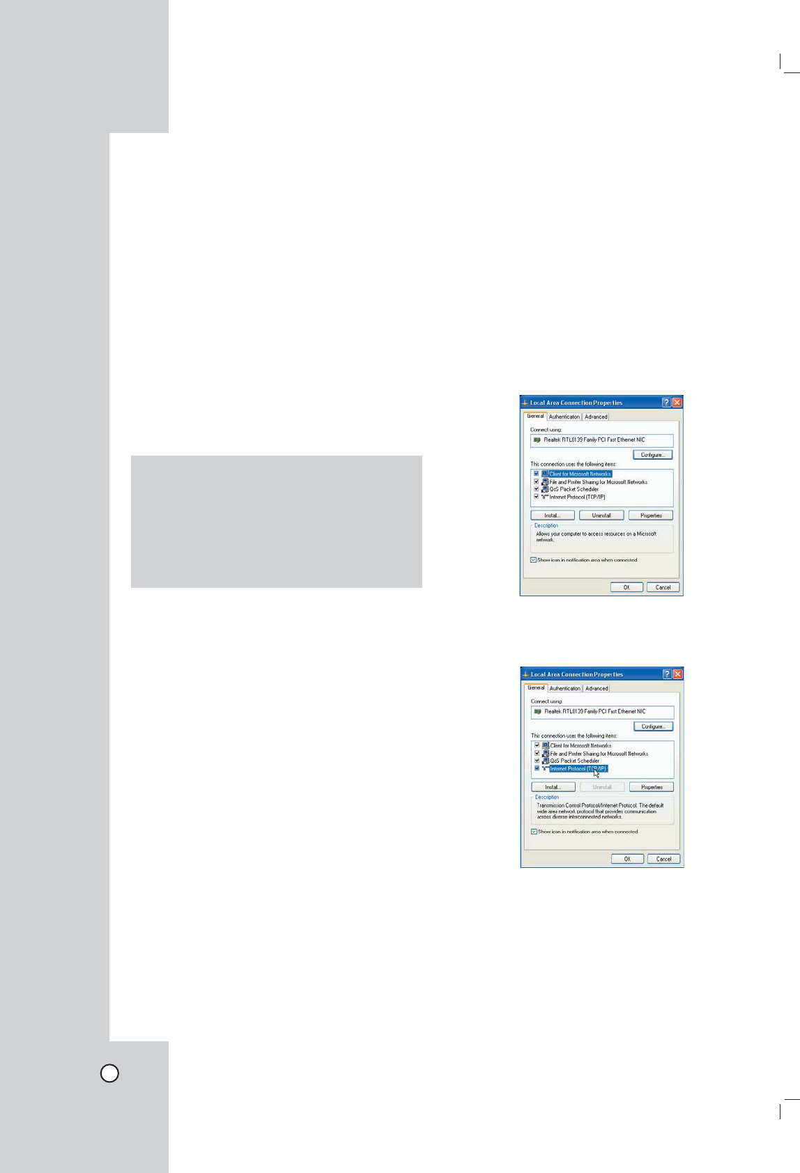
3. Set the network configuration of the computer as
shown below.
1) Open the [Local Area Connection Properties]
windows.
2) Select the [Internet Protocol [TCP/IP]] and
click [Properties].
3) Select the [Obtain an IP address automati-
cally] to use DHCP.
4) Click [OK] or [Close] repeatedly to save the
settings.
27
4. Start the web browser on the computer.
5. In the Address Box, enter "http://192.168.1.111".
6. Press ENTER and then the login page will be dis-
played.
Notes:
• The login page needs more time to display it
according to a network condition.
• If the login page is not displayed, check the
TCP/IP settings of the computer or the pop-up
blocker. If you set the pop-up blocker, the login
page is not displayed. You must allow the pop-
ups.
• If you connect the Netstation for the first time,
the Security Warning window is displayed to
install the VLC player. You must install the
VLC player for using the Web Viewer.
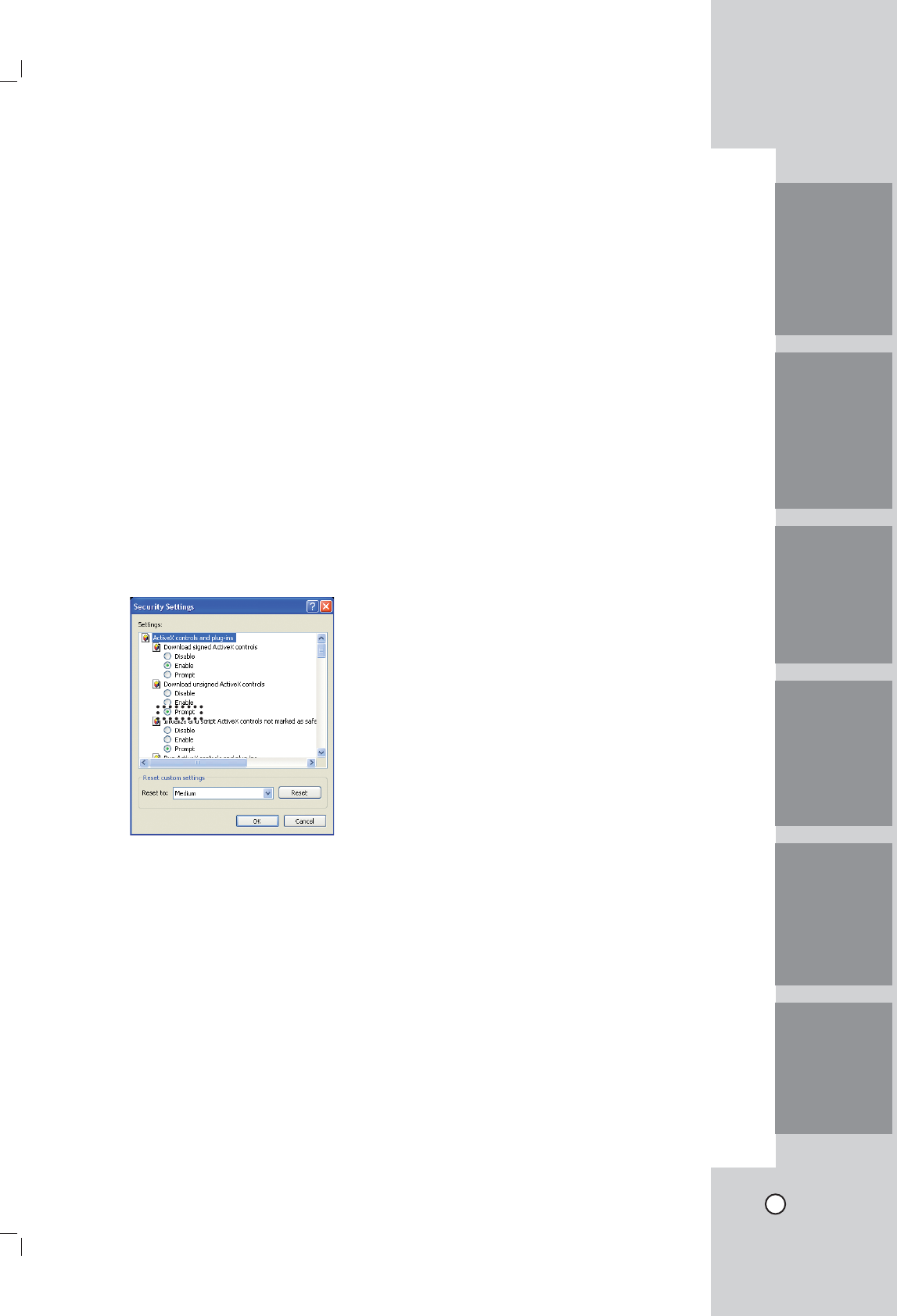
• If you block the ActiveX, you can not install
the VLC player. In that case, change the
"Download unsigned ActiveX controls" option
to "Prompt" in the Security Settings menu
(Tools > Internet Options... > Security tab >
Custom Level... > ActiveX controls and plug-
ins) of the browser.
• You can install the VLC player manually, visit
the "http://www.videolan.org" website and
download the VLC player for windows.
7. Select the User ID and enter the Password of
selected user ID. If you login the Netstation as
Administrator, you can not login using the web
viewer program.
8. Click the [Login]. The Web viewer is displayed.
Note:
The Web viewer is used only for one user.
Logging in to the Web Viewer
when the Computer and the
Netstation are connected via
internet
1. Connect a computer to the Internet.
2. Connect the internet cable to the WAN port of the
Netstation.
Note:
Ensure that your computer and the Netstation are
on the same network segment.
3. Turn on the computer and Netstation.
4. Check the IP Address of the Netstation. (See
page ??)
5. Start the web browser on the computer.
6. In the Address Box, enter "http://" and the IP
Address of the Netstation.
Note:
If you connect the Netstation to the Router, you
should set the Port Forwarding and use the IP
address of the Router to enter the web viewer.
Refer to the owner's manual of the Router for port
forwarding settings.
7. Follow steps 6-8 as shown [Logging in to the Web
Viewer when the Computer and the Netstation is
directly connected].
IntroductionHookup and
Settings
RecordingSearch and
Playback
Client
Program
Reference
28
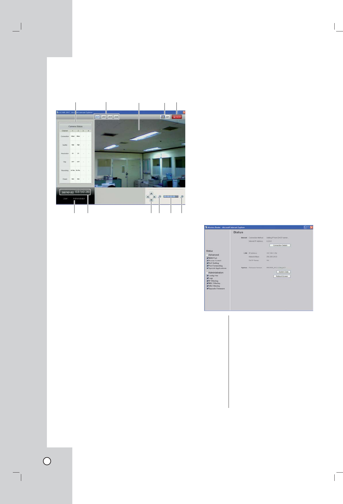
Using the Web Viewer
You can control the live image using the Web Viewer.
ab cde
fg hiji
a Camera Status Table
Shows the camera status.
b Camera channel buttons
Press the ch1 to ch4 channel button to see the
current surveillance images.
c Live screen
Displays the current surveillance live screen
d AP setup button
Click to go to the AP Setup menu.
This button is displayed only when a computer
and the Netstation are directly connected using
the network cabel.
e Log out button
Click to go to the log-in page of the Web viewer.
f Display the current date and time
g Display the current log-in User ID.
h The 4-direction arrow buttons
You can pan and tilt the camera using the 4-direc-
tion arrow buttons.
i Zooming buttons
You can operate the zoom range.
j Displays the current zoom level.
Note:
The d, h-j function is used for Administrator.
AP (Access Point) settings
An access point is a bridging device for connecting a
wired and wireless network together. Access points
are typically wireless routers or stand-alone devices
that plug into an Ethernet hub, switch, or router.
Wireless adapters should be set to Infrastructure
Mode when connecting to an access point or wireless
router. (Infrastructure: An 802.11 network in which
wireless devices communicate with each other by
first going through an Access Point (AP) or wireless
router.
If you want to change the AP options, refer to the fol-
lowing settings.
Click [AP] button and then display the Wireless
Router setup window.
Warning
If you change the AP settings without technical knowl-
edge, the Netstation may not be activated.
Status
Internet: Shows the internet connection sta-
tus.
Connection
Details:
Click to show more details of the
internet connection.
LAN: Shows the Local area network infor-
mation.
System: Briefly shows the device name and
firmware information.
System
Data:
Click to show the detailed informa-
tion of the system.
Refresh
Screen:
Click to refresh all the data.
29
IntroductionHookup and
Settings
RecordingSearch and
Playback
Client
Program
Reference
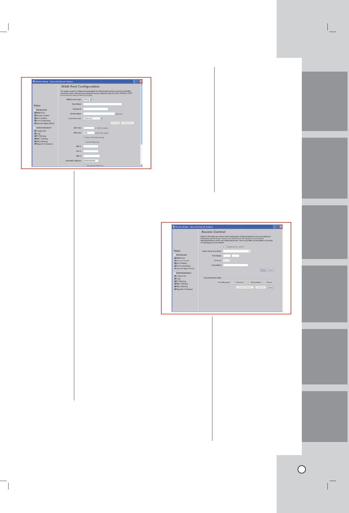
WAN Port Configuration
WAN Access Type: Select the WAN access type
(PPPoE, PPTP and L2TP)
from the pull-down menu.
Note:
You can set the Static IP or
DHCP setting in the Setup
menu of the Netstation.
User Name:
Password:
Service Name:
DNS 1-3: Enter the DNS server IP
address(es) provided by your
ISP, or you can specify your
own preferred DNS server IP
address(es). DNS 1 and DNS
2 servers are optional. You
can enter another DNS serv-
er’s IP address as a backup.
DNS 1 and DNS 2 servers
will be used when the DNS 1
server fails.
Clone MAC
Address:
Your ISP may require a partic-
ular MAC address in order for
you to connect to the Internet.
This MAC address is the PC’s
MAC address that your ISP
had originally connected your
Internet connection to. Type
in this Clone MAC address
in this section to replace the
WAN MAC address with the
MAC address of that PC.
• Respond to WAN
Ping
• Enable UPNP
• Enable IPsec
pass through on
VPN connection
• Enable PPTP
pass through on
VPN connection
• Enable L2TP pass
through on VPN
conenction
Check to enable the listed
functions.
Save: After completing the settings
on this page, click Save to
save the settings.
Reset: Click Reset to restore to
default values.
Access Control
Enable Access
Control:
Select to enable Access
Control function.
Select Services to
Block:
This lists all defined Services.
Select the Services you wish
to block.
Port Range: For TCP and UDP Services,
enter the beginning of the
range of port numbers used
by the service. If the service
uses a single port number,
enter it in both the start and
finish fields.
Protocol: Select the protocol (TCP, UDP
or Both) used to the remote
system or service.
Description: You may key in a description
for port range.
30
Save: After completing the settings
on this page, click Save to
save the settings.
Reset: Click Reset to restore to
default values.
Current Blocked
Table:
Note:
If you blocked some port(s), the Netstation may not
activate correctly.
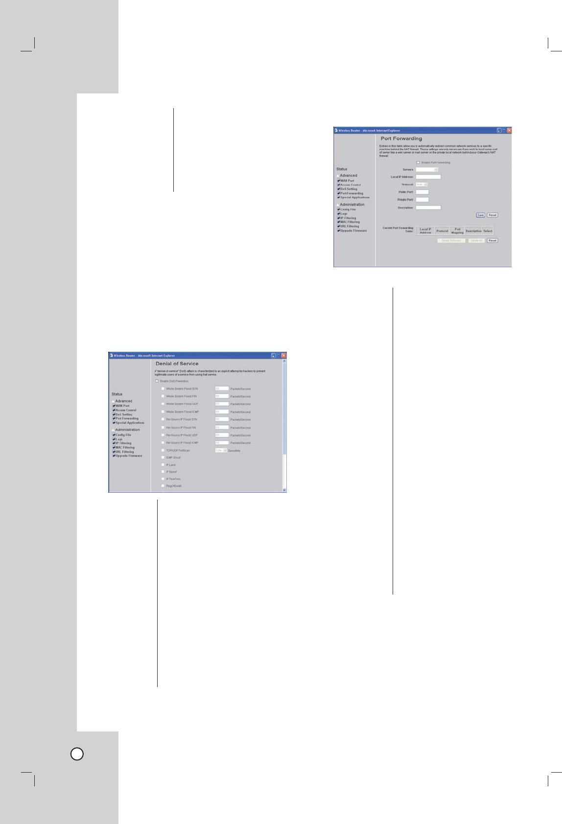
Denial of Service Setting
A DoS (Denial of Service) attack does not attempt to
steal data or damage your PCs, but overloads your
Internet connection so you cannot use it - the service
is therefore unavailable.
If DoS function is enabled, DoS attacks will be detect-
ed and blocked. The default is unabled. It is strongly
recommended that this setting be left enabled.
Enable DoS
Prevention:
Check to enable the DoS preven-
tion function. Select the item listed
to enable.
Enable Source
IP Blocking
s
Block time
(sec)
Set the threshold for the frequency
of packets that are allowed to
pass through. The default value is
50 packets per seconds. You can
adjust the value according to your
need. It is recommended that you
set a practical number so that your
network performance won’t be
hampered.
Select All Click to selct all listed items.
Clear All Click to clear all listed items.
Apply
Changes
Click to save the current settings.
Port Forwarding
Enable Port
Forwarding:
Check to enable the Port
Forwarding function.
Servers: Select the server.
Local IP
Address:
Enter the Local IP address.
Protocol: Select the protocol (TCP, UDP
or Both) used to the remote
system or service.
Public Port: Enter a public port number.
Private Port: Enter a private port number.
Description: You may key in a description
for port range.
Save: After completing the settings
on this page, click Save to
save the settings.
Reset: Click Reset to restore to
default values.
Current Port
Forwarding
Table:
Shows the current Port
Forwarding information.
Delete Selected: Click to delete selected item.
Delete All: Click to delete all listed items.
Reset: Click Reset to restore to
default values.
Note:
If you change the fort number that is registered auto-
matically from the system, you can not monitor using
the WAN
31
IntroductionHookup and
Settings
RecordingSearch and
Playback
Client
Program
Reference
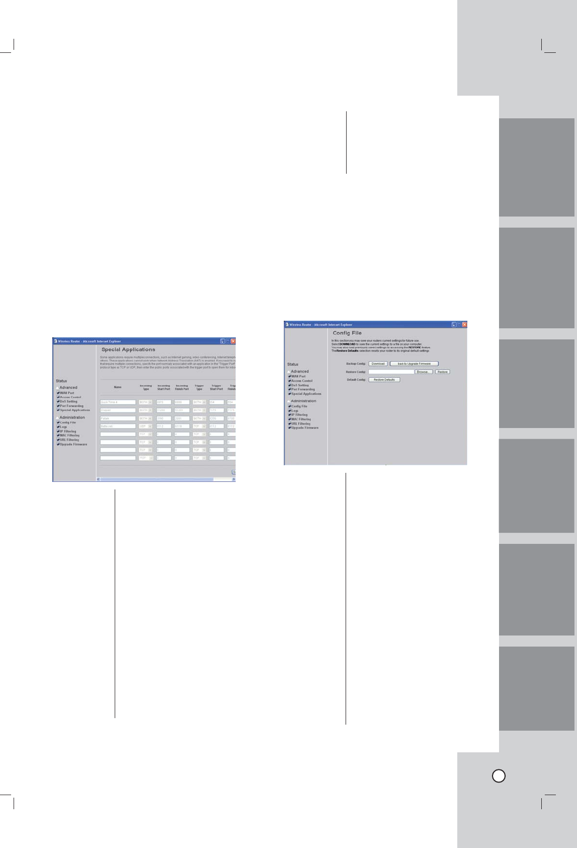
Special Application
Some software applications require special or multiple
connections to the Internet and these would normally
be blocked by the fi rewall. For example Internet
Telephony or Video conferences require multiple
connections. So that these special applications can
work properly and are not blocked, the fi rewall needs
to be told about them. In each instance there will be
a trigger port and incoming port(s), where traffi c on
the trigger port tells the fi rewall to open the incoming
ports.
Special Application allows the router to keep track of
outgoing data for specifi c port numbers. The router
remembers which computer sends out what data, so
when the requested data returns through the router,
the data is sent back to the proper computer by way
of IP address and port mapping rules.
You have to fi rstly check Enable before you can add/
edit an application.
Name: Enter the application name.
Incoming Type: Select the incoming application
type (TCP, UDP or BOTH)
Incoming Start
Port:
Enter a port number as the
incoming start port.
Incoming Finish
Port:
Enter a port number as the
incoming fi nish port.
Trigger Type: Select the trigger type (TCP,
UDP or BOTH)
Trigger Start
Port:
Enter a port number as the
starting outbound port for the
special application defi ned in
the preceding fi eld.
Trigger Finish
Port:
Enter a port number as the
ending outbound port for the
special application defi ned in
the preceding fi eld.
Enable: Mark up to change edit mode.
Save: Press to save the new settings
on the screen.
Undo: Press to discard the data you
have entered since last time
you press Save.
Config File
This feature allows you to download the current
settings from the Wireless Router, and save them to a
fi le on your PC.
You can restore a previously downloaded
confi guration fi le to the Wireless Router, by uploading
it to the Wireless Router.
This screen also allows you to set the Wireless Router
back to its factory default confi guration.
Any existing settings will be deleted.
Backup Confi g: Use this to download a copy of
the current confi guration, and
store the fi le on your PC. Click
Download to start the download.
Restore Confi g : This allows you to restore a
previously saved confi guration
fi le back to the Wireless Router.
Click Browse to select the
confi guration fi le, then
click Restore to upload the
confi guration fi le.
WARNING !
Uploading a confi guration fi le
will destroy (overwrite) ALL of
the existing settings.
Default Confi g: Clicking the Restore Defaults
button will reset the Wireless
Router to its factory default
settings. WARNING ! This
will delete ALL of the existing
settings.
32
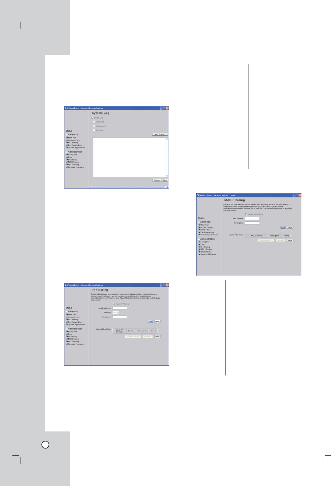
System Log
The Logs record various types of activity on
the Wireless Router. This data is useful for
troubleshooting, but enabling all logs will generate
a large amount of data and adversely affect
performance.
Enable Log: Click to enable log
function.
Apply Changes: After completing the
settings on this page,
click Save to save the
settings.
Refresh: Click to refresh the logs.
Clear: Click to delete the logs.
IP Filtering
Enable IP: Filtering Check to enable
the IP fi ltering function.
Local IP Address: Enter the client IP
address.
Protocol: Select the protocol (TCP,
UDP or Both) used to
the remote system or
service.
Description: You may key in a
description for the local
IP address
Current Filter Table: Shows the current fi lter
information.
Save: After completing the
settings on this page,
click Save to save the
settings.
Reset: Click Reset to restore to
default values.
MAC Filtering
Enable MAC
Filtering:
Check to enable MAC fi ltering
function.
MAC
Address:
Enter the client MAC address.
Description: You may key in a description for
the MAC address.
Current Filter
Table:
Shows the current fi lter
information.
Save: After completing the settings on
this page, click Save to save the
settings.
Reset: Click Reset to restore to default
values.
33
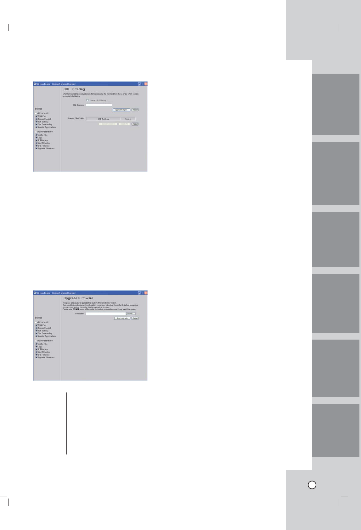
URL Filtering
Enable URL
Filtering:
Check to enable URL fi ltering
function.
URL Address: Enter the client URL address.
Current Filter
Table:
Shows the current fi lter
information.
Apply
Changes:
After completing the settings on
this page, click "Apply Changes"
to confi rm the settings.
Reset: Click Reset to restore to default
values.
Upgrade Firmware
Browse: Click the Browse button, fi nd
and open the fi rmware fi le (the
browser will display to correct fi le
path).
Start Upgrade: Click the Start Upgrade button to
perform
Reset: Click Reset to restore to default
values.
Note:
You should reboot the Netstation system after firm-
ware update.
IntroductionHookup and
Settings
RecordingSearch and
Playback
Client
Program
Reference

34
Reference
Troubleshooting
Check the following guide for the possible cause of a problem before contacting service.
Symptoms Resolutions
The system power
does not turn on.
Check the power cable is connected correctly.
Check the input voltage is correct.
The system power
is turned on but no
video data is dis-
played on the moni-
tor.
Check the monitor power cable is connected properly.
Make sure the monitor is turned on.
Check the video output cable of the Netstation is properly connected to
the monitor.
Unplug the power cable and plug in again.
The camera num-
bers are displayed
on the screen but
the camera images
are not
displayed.
Check the camera is connected to the Netstation correctly.
Check the power cable on the camera is connected correctly.
Check there is no problem with the LAN cable connection from the cam-
era to the Netstation.
Turn off theNetstation and turn it on again.
The camera video is
shown on the screen
but the system does
not record the video.
Check the recording mode in the record setting menu.
Check the USB device detection status in the live screen window.
Check the recordable disk space in the USB device.
It is impossible to
search through the
recorded video.
If there is no recorded video data, check the recording mode in the
record setting menu.
Check the user type. The search function is not available for a normal
user.
The colors of some
camera videos are
strange or videos
are displayed abnor-
mally.
If the camera connected to the Netstation has a problem, make sure
that the camera is not damaged by trying another camera into a working
video output.
There is a lot of
(screen) noise
accompanying the
image.
Check if there is any other problems in only the camera and if there is
any other external cause after connecting to other cameras.
Check if the LAN cable connection between the camera and the
Netstation.
Check if there is a high voltage wire around the LAN cable connection
between camera and Netstation. It can cause interference and affect
video quality.
Check the LAN cable connection between the camera and the Netstation
is the correct LAN cable.

35
Symptoms Resolutions
An E-mail sent
from this prod-
uct was not
received.
E-mail reception failed without SMTP server setting.
• Make sure the network is correctly set.
• Make sure the mail address is input correctly.
• Check the spam mail setting of the inputted mail address.
(If you set the spam mail, some mails are deleted automatically or classified in
the spam mail box)
• Some of SMTP mail services do not support an E-mails from private SMTP
servers. In this case use the public SMTP server.
E-mail reception failed even if the SMTP server was set.
• When the [Please check the SMTP information or internet cable] message is
displayed.
- Check the SMTP server address.
- Check the SMTP port number. (Default setting is 25).
- Check the network settings.
• When the [Please check the authentication information] message is displayed.
- Check the user name.
- Check the password.
• The mail reception failed without error message.
- Check the receiver’s mail address.
- Check your E-mail is not classified as a spam mail on the receiver's mail set-
ting.
The remote
control does not
work properly.
Check the batteries in the remote control.
Note:
If you observe any of the following symptoms:
• Some of the front panel LEDs do not light.
• The NetStation does not operate normally.
You can reboot the NetStation as follows:
• Turn off the NetStation and turn it on again after a few seconds.
When the recorder does not work normally after rebooting, contact the service center.
IntroductionHookup and
Settings
RecordingSearch and
Playback
Client
Program
Reference

36
Recommended devices
Supported external USB device list
No Maker Model Name Capacity USB Ver.
1 FM Memorette 1GB 2.0
2 FM Memorette 2GB 2.0
3 IOCell CellDisk 1GB 2.0
4 LG Xtic 1GB 2.0
5 SanDisk Cruzer 4GB 2.0
6 Toshiba 2.5" HDD 80GB 2.0
7 Hitachi 3.5" HDD 250GB 2.0
8 Transcend JF110/JF150 1/2GB 2.0
Notes:
• If the capacity of USB device has under 1GB or over 250GB, the USB device may not operate correctly.
• If you format the external USB device by using the other unit with NTFS or OS32 file system, the USB
device may not be used on this unit. Use the FAT 32 file system for this unit. You can format the USB
device as FAT 32 file system by using the format function in the Setup menu of the Netstation.
• Do not use the USB device via the USB Hub.
• Check the write speed of the USB and use it more than 2.5 Mbyte/sec write speed.
The necessary Capacity for 1Hour recording (Approximatly)
Resolution Quality 1ch 2ch 3ch 4ch
D1
Low 113MB 226MB 340MB 450MB
Middle 225MB 450MB 675MB 900MB
High 450MB 900MB 1.35GB 1.8GB
CIF
Low 56MB 113MB 168MB 225MB
Middle 113MB 225MB 340MB 450MB
High 225MB 450MB 675MB 900MB
Note:
This recording capacity table is only for reference.
The recording capacity can be different depending on the recording image.
In case of external 250GB HDD, the recording time is approximatly 176hours.

37
Factory default configuration settings
1st 2nd 3rd Data Range Default
Camera Information
Registration
Record Target Media None / USB-Rear / USB-Front None
Size
Format
USB Test
Rec. Setting
Display Language ENG ENG
OSD On / Off On
Dwell Time Off / 2 / 5 / 10 / 30 / 60 sec Off
Network Wan Port Type DHCP / Static / (Others) DHCP
IP Address 0.0.0.0 ~ 255.255.255.255 Null
Subnet Mask 0.0.0.0 ~ 255.255.255.255 Null
Gateway 0.0.0.0 ~ 255.255.255.255 Null
DNS DHCP On / Off On
Main DNS 0.0.0.0 ~ 255.255.255.255 Null
Sub DNS 0.0.0.0 ~ 255.255.255.255 Null
DDNS DDNS On / Off Off
Provider DynDNS / TZO DynDNS
Domain URL A~Z, 0~9, Special Character Null
ID A~Z, 0~9, Special Character Null
Password A~Z, 0~9, Special Character Null
Sender Mail Mail Send On / Off Off
SMTP Server A~Z, 0~9, Special Character Null
Mail Address A~Z, 0~9, Special Character Null
Password A~Z, 0~9, Special Character Null
Receiver Mail Address 1 A~Z, 0~9, Special Character Null
Address 2 A~Z, 0~9, Special Character Null
Address 3 A~Z, 0~9, Special Character Null
Address 4 A~Z, 0~9, Special Character Null
Notification Motion Detect On / Off Off
Disc Full On / Off Off
Admin PW
Changed
On / Off Off
Camera
Disconnect
On / Off Off
Wireless Wireless On / Off On
SSID A~Z, 0~9 HMS-AP-xxxx
Band 2.4GHz (B+G) / 2.4GHz (G) 2.4GHz (G)
Channel Auto / 1 ~ 11 Auto
WEP Key Off, a ten digit numbers (HEX
code)
Off
IntroductionHookup and
Settings
RecordingSearch and
Playback
Client
Program
Reference

38
1st 2nd 3rd Data Range Default
System Clock Clock Mode Auto / Manual Manual
Date YYYY / MM / DD Current Date
Time HH : MM Current Time
NTP Server North America 1~3 / Europe
1~2 / Australia / Asia Pacific
North America 1
Time Zone GMT-12 ~ GMT+12 GMT
Daylight Saving On / Off Off
User Password Admin 4~8 digit number Null
Normal 4~8 digit number 0000
Auto Log Out Off / 5 /10 / 30 / 60 min Off
Beep On / Off Off
Factory Reset Reset

39
IntroductionHookup and
Settings
RecordingSearch and
Playback
Client
Program
Reference
Specifications
ITEM LSP-W1000
Video
Video Format NTSC / PAL
Input 4
Output Composite 1
VGA 1
Resolution 640x480, 320x240
Audio Input 4
Output 1
Motion Intput OK
Notifi cation to e-mail OK
Recording
Frame Rate (/Sec) Max. 7.5 VGA Frames/Sec/Ch
Recording Mode Continuous / Motion / Instant Record
Storage Ext. USB Storage
Search / Playback
Playback
Control Mode
Normal / Still / Stop
Fast / Slow Forward
Fast / Slow Backward
Search Mode Date / Time / File
Display
Division Mode 1 / 4
Motion Alert Mode Buzzer
Language English
Menu Screen GUI
Information OK
Pan/Tilt Angle Pan: -50º to +50º, Tilt: -40º to +10º
Zoom Digital X4, 5 Steps
Auto Sequence mode OK
Network
LAN
Number of ports 4
Connector type Ethernet RJ-45
Physical 100Base-TX/10Base-T
Wireless
(IEEE802.11b/g)
Transmission
protocol
(802.11g)
DS-SS, OFDM
Transmission
protocol
(802.11b)
DS-SS
Transmission
speed (802.11g) 54/48/36/24/18/12/9/6 Mbps
Transmission
speed (802.11b) 11/5.5/2/1 Mbps
Frequency
range (MHz) (2.412 - 2.484 GHz)
Number of
channels (1~14 ch )
User RESET button OK
Mode switch OK

40
ITEM LSP-W1000
Security
WEP Encryption 64/128Bit
wireless stealth functionality ESSID
MAC address fi ltering OK
User Level Control OK
I/O
Front
LED 10
USB 1 port
RCU sensor 1
Rear
DC In 1
RCA Jack 1 Audio / 1 Video
D-Sub VGA Video
RJ-45 5
DIP Switch 2
USB 1
RESET button 1
Antenna 1
Etc
Password Protection OK
Password Reset OK
Log List OK
Web Client OK
Button Lock OK
Buzzer OK
General
Video Codec MPEG4
Audio Codec G.726
Power Source DC Adapter
Power Consumption
Dimension (WxDxH mm)
Weight
Operation Humidity
Operation Temp.

P/NO: MFL3????