LG Electronics USA 9QKA2920 VCR User Manual VCP354 Instruction
LG Electronics USA VCR VCP354 Instruction
UserManual.wiki
>
LG Electronics USA
>
9QKA2920 User Manual
Users Manual
Navigation menu
Upload a User Manual
Namespaces
Wiki Guide
HTML
PDF
Info
Views
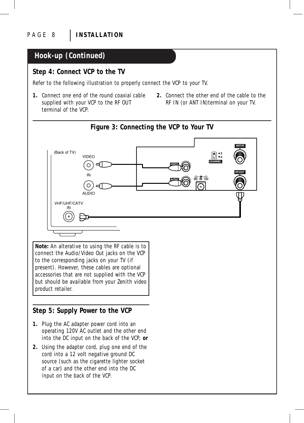
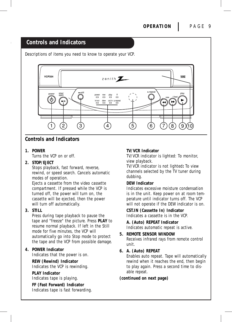
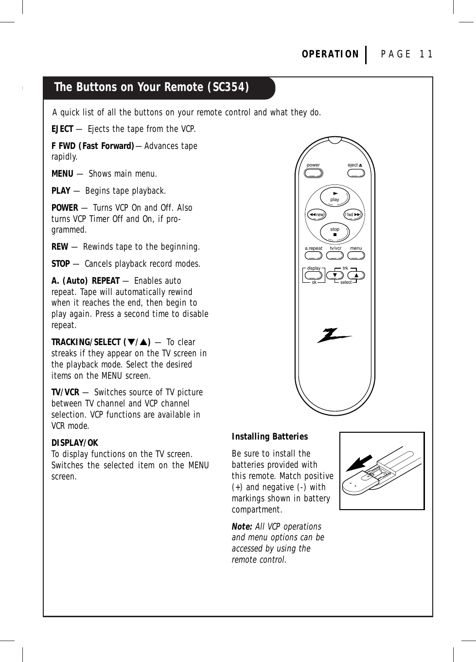
User Manual
Discussion / Help
Navigation