LG Electronics USA 9QKA2920 VCR User Manual VCP354 Instruction
LG Electronics USA VCR VCP354 Instruction
Users Manual

• Manual (2 ~17Page)
• Label (18)
• Block Diagram (19~22)
• Modulator Specification (23~30)
Appendix

VCP
OWNER’S MANUAL
MODEL: AS106M
Before connecting, operating, or adjusting this
product, please read this instruction booklet
carefully and completely.
INTRODUCTION PREPARATION PLAYBACK ADDITIONAL INFORMATION
WARNING:
TO REDUCE THE RISK OF ELECTRIC SHOCK DO NOT REMOVE COVER (OR BACK). NO USER SERVICEABLE
PARTS INSIDE. REFER SERVICING TO QUALIFIED SERVICE PERSONNEL.
The lightning flash with arrowhead symbol, within an equilateral triangle, is intended to alert the
user to the presence of uninsulated “dangerous voltage” within the product’s enclosure that may be
of sufficient magnitude to constitute a risk of electric shock to persons.
The exclamation point within an equilateral triangle is intended to alert the user to the presence of
important operating and maintenance (servicing) instructions in the literature accompanying the
appliance.
WARNING:
TO REDUCE THE RISK OF FIRE OR ELECTRIC SHOCK, DO NOT EXPOSE THIS APPLIANCE TO RAIN OR
MOISTURE.
POWER CORD POLARIZATION:
CAUTION: To Prevent Electric Shock, match wide blade of plug to wide slot, fully insert.
ATTENTION: Pour éviter les chocs électriques, introduire la lame la plus large de la fiche dans la borne
correspondante de la prise et pousser jusqu’au fond.
NOTE TO CABLE/TV INSTALLER:
This reminder is provided to call the cable TV system installer’s attention to Article 820-40 of the
National Electric Code (U.S.A.). The code provides guidelines for proper grounding and, in particular,
specifies that the cable ground shall be connected to the grounding system of the building, as close to
the point of the cable entry as practical.
REGULATORY INFORMATION:
This equipment has been tested and found to comply with the limits for a Class B digital device,
pursuant to Part 15 of the FCC Rules. These limits are designed to provide reasonable protection against
harmful interference when the equipment is operated in a residential installation. This equipment
generates, uses and can radiate radio frequency energy and, if not installed and used in accordance with
the instruction manual, may cause harmful interference to radio communications. However, there is no
guarantee that interference will not occur in a particular installation. If this equipment does cause
harmful interference to radio or television reception, which can be determined by turning the equipment
off and on, the user is encouraged to try to correct the interference by one or more of the following
measures: • Reorient or relocate the receiving antenna.
• Increase the separation between the equipment and receiver.
• Connect the equipment into an outlet on a circuit different from that to which the
receiver is connected.
• Consult the dealer or an experienced radio/TV technician for help.
CAUTION:
Do not attempt to modify this product in any way without written authorization from Zenith Electronics
Corporation. Unauthorized modification could void the user’s authority to operate this product.
This class B digital apparatus meets all requirements of the Canadian Interference-Causing Equipment
Regulations.
“Ce appareil numérique de la class b respecte toutes les exigences du Règulement sur le matériel
brouillier du Canada.”
Zenith is a trademark of ZEC © Copyright Zenith Electronics Corporation 1999
WARNING
RISK OF ELECTRIC SHOCK
DO NOT OPEN
IMPORTANT SAFETY INSTRUCTIONS
SAFETY TIPS PAGE 3
These simple precautions will help ensure that you get many years of safe enjoyment from your new product.
1. Read Instructions
Read all of the safety and operating instructions
before operating the product.
2. Retain Instructions
Keep all safety and operating instructions for
future reference.
3. Heed Warnings
Follow warnings on the product and in the
operating guide.
4. Follow Instructions
Follow all operating and use instructions.
5. Cleaning
Unplug this product from the wall outlet before
cleaning. Do not use liquid cleaners or aerosol
cleaners. Use a damp cloth for cleaning.
6. Attachments
Do not use attachments not recommended by
product manufacturer as they may cause
hazards.
7. Water and Moisture
Do not use this product near water—for
example, near a bathtub, wash bowl, sink, or
laundry tub, in a wet basement, or near a
swimming pool.
8. Accessories
Do not place product on an unstable cart, stand,
tripod, bracket, or table. Product may fall,
causing serious injury to a child or adult, and
serious damage to the product. Use only with a
cart, stand, tripod, bracket, or table
recommended by the manufacturer or sold with
the product. Any mounting of product should
follow manufacturer’s instructions and should
use a mounting accessory recommended by
manufacturer.
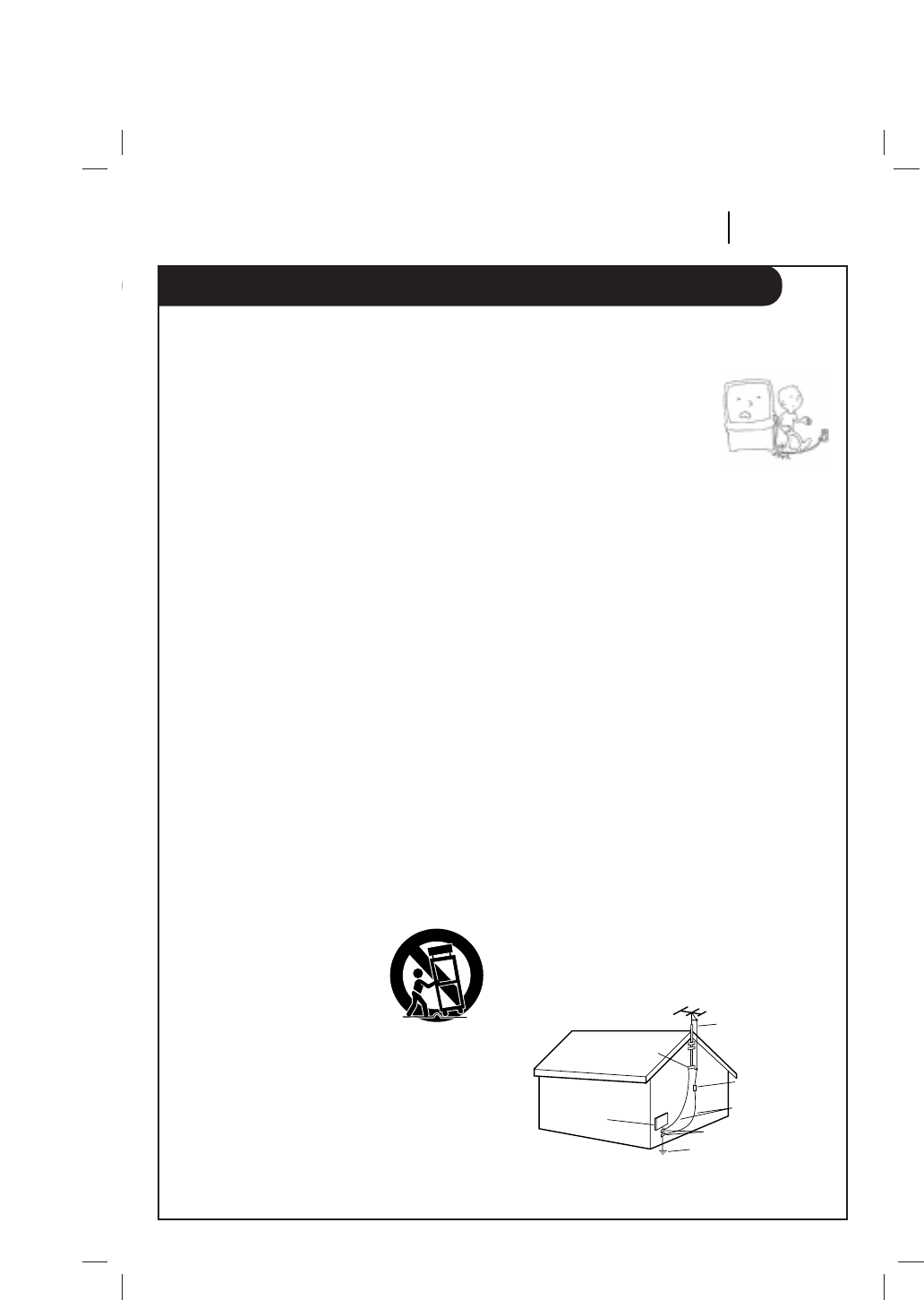
9. Transporting Product
Move product and cart
combinations with care. Quick
stops, excessive force, and
uneven surfaces may cause
product and cart combination
to overturn.
10. Ventilation
Slots and openings in cabinet must not be
blocked or covered. They are provided for venti-
lation, to ensure reliable operation, and to pro-
tect from overheating. Never block openings by
placing product on a bed, sofa, rug, or other
similar surface. Do not place product in built-in
installation such as a bookcase or rack unless
proper ventilation is provided or manufacturer’s
instructions have been adhered to.
11. Power Sources
Operate product only from
type of power source
indicated on marking label.
If you are not sure of the
type of power supply to your
home, consult your product
dealer or local power
company. For products intended to operate from
battery power or other sources, refer to manual.
12. Line-Cord Polarization
Product is equipped with a polarized
alternating-current line plug (a plug having one
blade wider than the other). As a safety feature,
this plug will fit into power outlet only one way.
If you’re unable to insert plug fully into outlet,
try reversing the plug. If plug still fails to fit,
contact an electrician to replace your obsolete
outlet. Do not defeat safety purpose of
polarized plug.
13. Power-Cord Protection
Route power-supply cords so they are not likely
to be walked on or pinched by items placed
upon or against them, paying particular atten-
tion to cords at plugs, convenience receptacles,
and the point where they exit from product.
14. Outdoor Antenna Grounding
If an outside antenna or cable system is con-
nected to this product, be sure antenna or cable
system is grounded so as to provide some pro-
tection against voltage surges and built-up stat-
ic charges. Article 810 of the National Electrical
Code (USA), ANSI/NFPA 70 provides information
on grounding of mast and supporting structure,
grounding of lead-in wire to an antenna
discharge unit connection to grounding
electrodes, and requirements for grounding elec-
trode.
( See Fig. 1 on the below. )
Antenna Lead-in Wire
Antenna Discharge Unit
NEC Section 810-20
Grounding Conductors
NEC Section 810-21
Ground Clamps
Power Service Grounding
Electrode System
NEC Art 250, Part H
Ground
Clamp
Electric Service
Equipment
NEC: National Electrical Code
Antenna grounding per NEC Code, ANSI/NFPA 70
Fig. 1
IMPORTANT SAFETY INSTRUCTIONS
PAGE 4 SAFETY TIPS
These simple precautions will help ensure that you get many years of safe enjoyment from your new product.
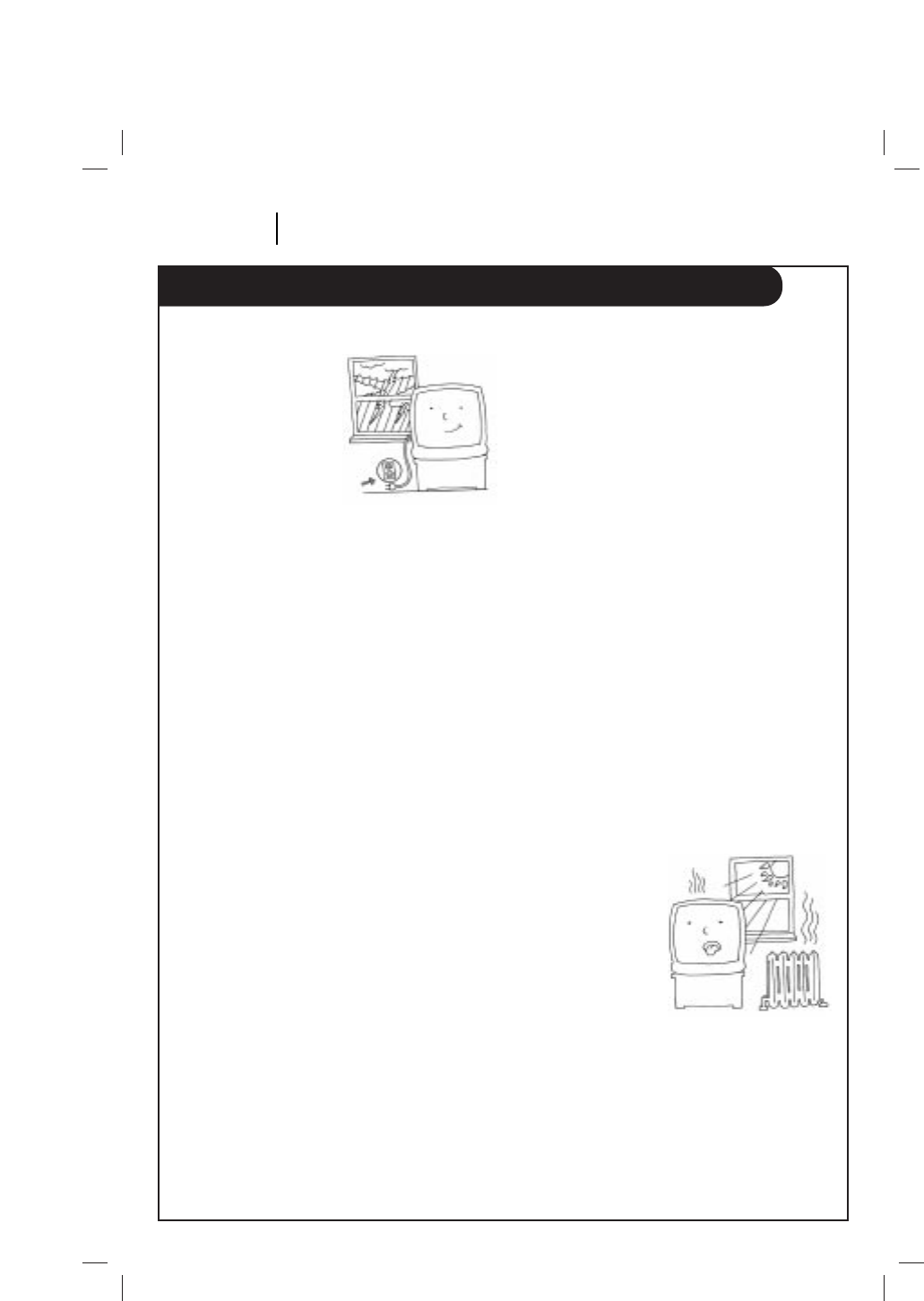
15. Lightning
For added protection
for this product during
a lightning storm, or
when product is left
unattended and
unused for long
periods of time,
unplug it from the
wall outlet and disconnect antenna or cable
system. This will prevent damage to product due
to lightning and power line surges.
16. Power Lines
An outside antenna system should not be
located in the vicinity of overhead power lines
or other electric light or power circuits, or where
it can fall into such power lines or circuits.
When installing an outside antenna system, take
extreme care to keep from touching such power
lines or circuits, as contact with them might be
fatal.
17. Overloading
Do not overload wall outlets, extension cords or
integral convenience receptacles, as this can
result in risk of fire or electric shock.
18. Object and Liquid Entry
Never push objects of any kind into this product
through openings, as they may touch dangerous
voltage points or short-out parts that could
result in fire or electric shock. Never spill liquid
of any kind on product.
19. Servicing
Do not attempt to service this product yourself,
as opening or removing covers may expose you
to dangerous voltage or other hazards. Refer all
servicing to qualified service personnel.
20. Wall or Ceiling Mounting
Mount product to wall or ceiling only as
recommended by manufacturer.
21. Replacement Parts
When replacement part(s) are required, be sure
service technician has used replacement part(s)
specified by manufacturer or have same
characteristics as original part(s). Unauthorized
substitutions may result in fire, electric shock,
or other hazards.
22. Damage Requiring Service
Unplug this product from the wall outlet and
refer servicing to qualified service personnel
under these conditions:
a. If power-supply cord or plug is damaged.
b. If liquid has been spilled or objects have
fallen into product.
c. If product has been exposed to rain or water.
d. If product doesn’t operate normally by
following handbook instructions. Adjust only
those controls covered by handbook
instructions; improper adjustment of other
controls may result in damage and often
requires extensive work by a qualified
technician to restore product to normal
operation.
e. If product has been dropped or cabinet has
been damaged.
f. If product exhibits a distinct change in
performance.
23. Heat
Keep product away
from heat sources
such as radiators,
heat registers,
stoves, or other
products (including
amplifiers) that
produce heat.
24. Safety Check
Upon completion of any service or repairs to
this
product, ask service technician to perform safety
checks to determine that product is in proper
operating condition.

Contents
INSTALLATION PAGE 5
SAFETY TIPS . . . . . . . . . . . . . . . . . . . . . . . . . . . . . . . . . . . . . . . . . . . . . . . . . . . . . .2-4
Hook-up . . . . . . . . . . . . . . . . . . . . . . . . . . . . . . . . . . . . . . . . . . . . . . . . . . . . . . . . .6-8
Operation . . . . . . . . . . . . . . . . . . . . . . . . . . . . . . . . . . . . . . . . . . . . . . . . . . . . . . .9-13
Controls and Indicators . . . . . . . . . . . . . . . . . . . . . . . . . . . . . . . . . . . . . . . . . . . . .9-10
The Buttons on Your Remote . . . . . . . . . . . . . . . . . . . . . . . . . . . . . . . . . . . . . . . . . .11
VCP Status Displays . . . . . . . . . . . . . . . . . . . . . . . . . . . . . . . . . . . . . . . . . . . . . . .12
How to using menu . . . . . . . . . . . . . . . . . . . . . . . . . . . . . . . . . . . . . . . . . . . . . . . .13
Troubleshooting & Maintenance . . . . . . . . . . . . . . . . . . . . . . . . . . . . . . . . . . . . . . . . .14
Specifications . . . . . . . . . . . . . . . . . . . . . . . . . . . . . . . . . . . . . . . . . . . . . . . . . . . . .15
Warranty . . . . . . . . . . . . . . . . . . . . . . . . . . . . . . . . . . . . . . . . . . . . . . . . . . . Back Cover
Note: This video cassette player is for video playback
only. Recording is not possible with this unit.
Hook-up
PAGE 6 INSTALLATION
Your VCP has been designed to transmit a signal
to channel 3 or 4 of your TV, TO get the proper
TV signal, set the Channel 3/4 switch on the
back of the VCP to the channel that provides
the best picture.
When playing a tape, the TV
must be tuned to the same
channel (3 or 4) as the
Channel 3/4 switch on the
VCP.
Note:
This only applies when the RF OUT connection is
used. If the VCP is connected to your TV via the
Audio/Video output jacks also, choose
appropriate input source at the TV, (TV Channel
3/4 or Audio/Video In.)
Step 2: Select the Output Video Channel
3
4
Refer to the following steps to hook up your Video Cassette Player easily and quickly.
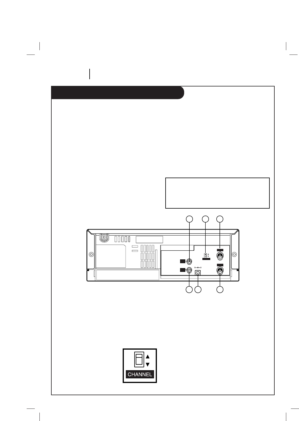
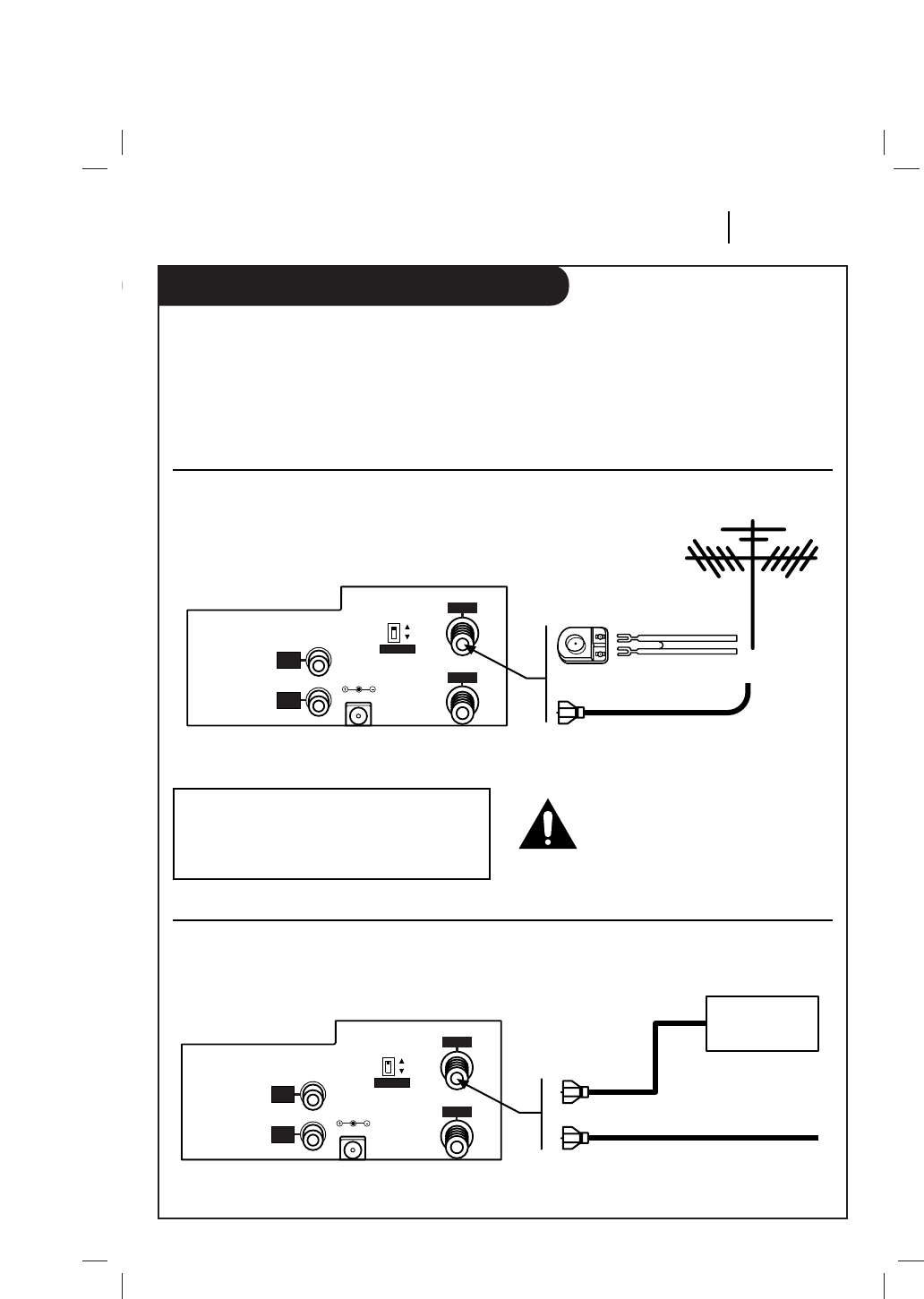
Step 1: Identify the Connectors and Switches
Locate the following connectors and switch on the back of your VCP;
1. Video Out Jack
Video output must be used in conjunction
with audio out connection.
2. Channel 3/4 Switch
Output video channel switch.
3. Ant In Jack
Input from external antenna or cable-TV
Line.
4. RF Out Jack
Output to television.
5. DC Input Jack
Input from optional DC power source.
6. Audio Out Jack
Audio output must be used in conjunction
with video out connection.
Note: Use of the Audio/Video Output jacks is
optional. Depending on the capability of your
TV, you may get improved picture quality
when using these connections.
3
DC IN 12V
4
CHANNEL
RF.OUT
ANT.IN
VIDEO
OUT
AUDIO
OUT
1 2 3
456
Hook-up (Continued)
INSTALLATION PAGE 7
1. Disconnect the antenna or cable-TV line
from the TV. 2. Connect the antenna or cable-TV line to
the ANT IN terminal on the VCP.
Step 3: Connect VCP to Antenna or Cable-TV Line
Your antenna/cable-TV connection will be similar to one of the illustrations below.
Match yours to the one like it and make the connections shown.
Note: The 300/75 ohm adapter is an optional
accessory that is not supplied with the VCP
but should be available from your Zenith
video product retailer.
Figure 2a: Antenna Connection
3
DC IN 12V
4
CHANNEL
RF.OUT
ANT.IN
VIDEO
OUT
AUDIO
OUT
Flat Wire
300/75 ohm
Adapter
Round Wire
or
3
DC IN 12V
4
CHANNEL
RF.OUT
ANT.IN
VIDEO
OUT
AUDIO
OUT
CH 3/4
Output DECODER/
CONVERTER
(Direct Connection)
or
CABLE-TV
Turn off power or unplug VCP
before making any connections.
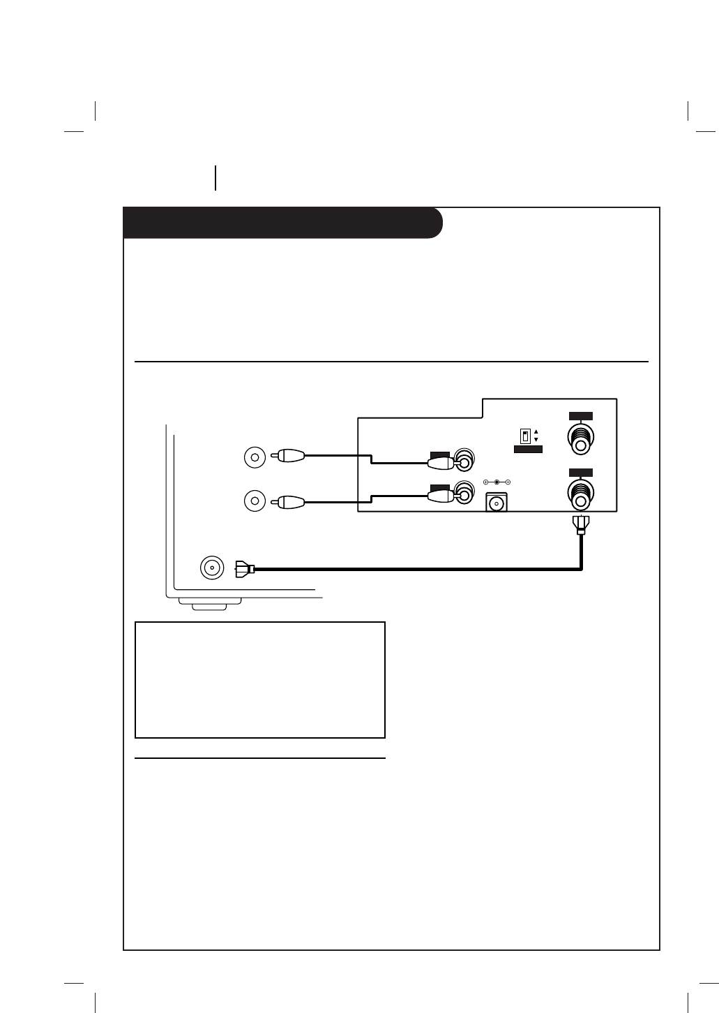
Figure 2b: Cable-TV Connection
Hook-up (Continued)
PAGE 8 INSTALLATION
1. Connect one end of the round coaxial cable
supplied with your VCP to the RF OUT
terminal of the VCP.
2. Connect the other end of the cable to the
RF IN (or ANT IN)terminal on your TV.
Step 4: Connect VCP to the TV
Refer to the following illustration to properly connect the VCP to your TV.
1. Plug the AC adapter power cord into an
operating 120V AC outlet and the other end
into the DC input on the back of the VCP, or
2. Using the adapter cord, plug one end of the
cord into a 12 volt negative ground DC
source (such as the cigarette lighter socket
of a car) and the other end into the DC
input on the back of the VCP.
Figure 3: Connecting the VCP to Your TV
Note: An alterative to using the RF cable is to
connect the Audio/Video Out jacks on the VCP
to the corresponding jacks on your TV (if
present). However, these cables are optional
accessories that are not supplied with the VCP
but should be available from your Zenith video
product retailer.
Step 5: Supply Power to the VCP
3
DC IN 12V
4
CHANNEL
RF.OUT
ANT.IN
VIDEO
OUT
AUDIO
OUT
VHF/UHF/CATV
IN
IN
VIDEO
AUDIO
(Back of TV)
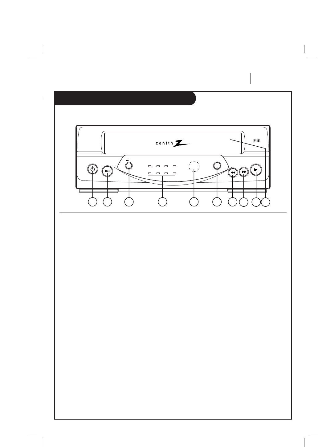
Controls and Indicators
OPERATION PAGE 9
Descriptions of items you need to know to operate your VCP.
1. POWER
Turns the VCP on or off.
2. STOP/EJECT
Stops playback, fast forward, reverse,
rewind, or speed search. Cancels automatic
modes of operation.
Ejects a cassette from the video cassette
compartment. If pressed while the VCP is
turned off, the power will turn on, the
cassette will be ejected, then the power
will turn off automatically.
3. STILL
Press during tape playback to pause the
tape and "freeze" the picture. Press PLAY to
resume normal playback. If left in the Still
mode for five minutes, the VCP will
automatically go into Stop mode to protect
the tape and the VCP from possible damage.
4. POWER Indicator
Indicates that the power is on.
REW (Rewind) Indicator
Indicates the VCP is rewinding.
PLAY Indicator
Indicates tape is playing.
FF (Fast Forward) Indicator
Indicates tape is fast forwarding.
TV/VCR Indicator
TV/VCR indicator is lighted: To monitor,
view playback.
TV/VCR indicator is not lighted:To view
channels selected by the TV tuner during
dubbing.
DEW Indicator
Indicates excessive moisture condensation
is in the unit. Keep power on at room tem-
perature until indicator turns off. The VCP
will not operate if the DEW indicator is on.
CST.IN (Cassette In) Indicator
Indicates a cassette is in the VCP.
A. (Auto) REPEAT Indicator
Indicates automatic repeat is active.
5. REMOTE SENSOR WINDOW
Receives infrared rays from remote control
unit.
6. A. (Auto) REPEAT
Enables auto repeat. Tape will automatically
rewind when it reaches the end, then begin
to play again. Press a second time to dis-
able repeat.
(continued on next page)
Controls and Indicators
1 2 3 4 5 6 7 8 9 10
power stop/
eject still play
rew f fwd
power rew
dew
play f
f
cst.in a.repeat
a.repeat
tv/vcr
VCP354

Controls and Indicators (Continued)
PAGE 10 OPERATION
7. REW (Rewind/Reverse Search) Button
Press while the VCP is in Stop mode to
rewind the tape (no picture, no sound).
During tape playback, press to begin
Reverse Search; The picture portion of the
tape is played in the reverse direction at
high speed (sound is muted). Press STOP to
end rewind or search.
8. F FWD (Fast Forward/Forward Search)
Press while the VCP is in the Stop mode to
fast forward the tape (no picture or sound).
During tape playback, press to begin
Forward search; The picture portion of the
tape is played at high speed (the sound is
muted). Press STOP to end fast forward or
search.
9. PLAY
Begins tape playback. The correct playback
speed is automatically selected.
10.Cassette Loading Compartment
Insert a VHS video cassette into the video
cassette compartment until it is automati-
cally drawn into the VCP. The cassette can
be inserted even when power is off. Power
turns on automatically and playback begins.
CAUTION; DO NOT attempt to insert a cas-
sette into the compartment when the power
cord is unplugged.
CAUTION; DO NOT insert fingers into the
cassette compartment.
Playing a Video Cassette
• Turn on the TV.
• If the VCP is connected to the TV via the RF
OUT jack, tune the TV to the same channel
(3 or 4) as the Channel 3/4 switch on the
back of the VCP.
• If the connection in mode via the VCP's
Audio/Video Out jacks, your TV must be set
to receive audio and video from an auxiliary
source. (Refer to your TV operating instruc-
tions.)
• To view a VHS cassette tape, insert it into
the cassette compartment. The VCP will
automatically turn on, play the tape to its
end, rewind the tape, eject the tape, and
shut off. If necessary, use the TRK (TRACK-
ING) control to adjust for the best picture.
Normal TV Viewing
To watch TV, simply place VCP in TV mode by
pressing TV/VCR on the remote repeatedly until
the TV/VCR indicator light disappears from the
VCP front panel. If the TV antenna or cable-TV
line has been connected to the VCP as shown
in this manual, its signal will pass through the
turned-off VCP unaffected, as if connected
directly to the TV.
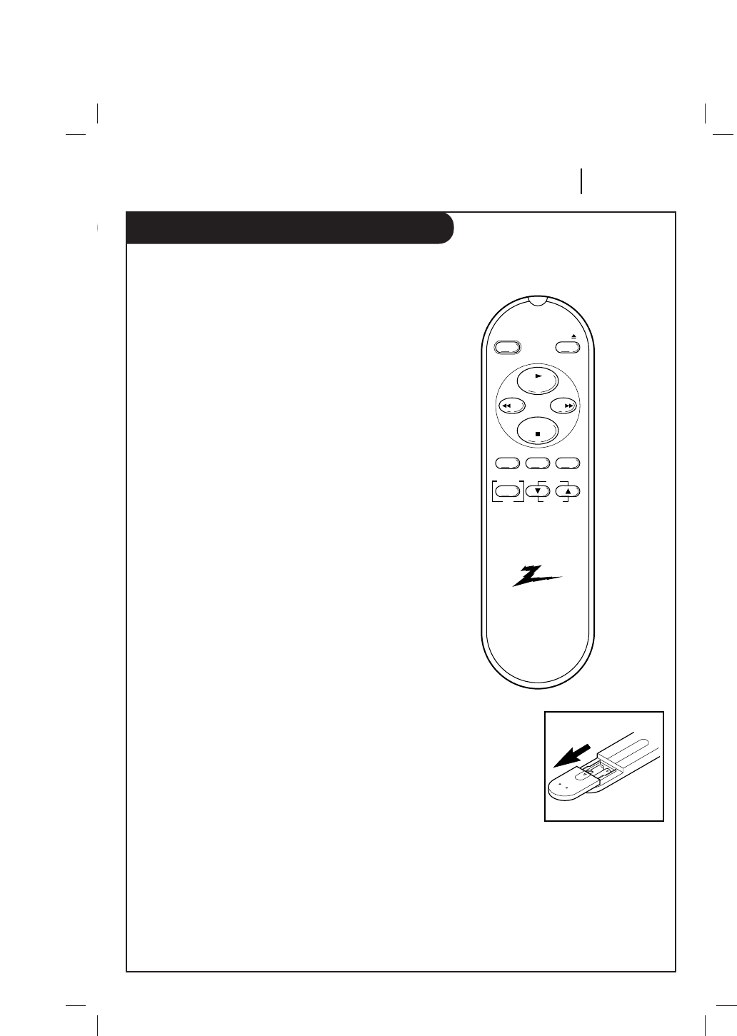
The Buttons on Your Remote (SC354)
OPERATION PAGE 11
A quick list of all the buttons on your remote control and what they do.
Installing Batteries
Be sure to install the
batteries provided with
this remote. Match positive
(+) and negative (-) with
markings shown in battery
compartment.
Note: All VCP operations
and menu options can be
accessed by using the
remote control.
EJECT — Ejects the tape from the VCP.
F FWD (Fast Forward)—Advances tape
rapidly.
MENU — Shows main menu.
PLAY — Begins tape playback.
POWER — Turns VCP On and Off. Also
turns VCP Timer Off and On, if pro-
grammed.
REW — Rewinds tape to the beginning.
STOP — Cancels playback record modes.
A. (Auto) REPEAT — Enables auto
repeat. Tape will automatically rewind
when it reaches the end, then begin to
play again. Press a second time to disable
repeat.
TRACKING/SELECT (▼/▲)— To clear
streaks if they appear on the TV screen in
the playback mode. Select the desired
items on the MENU screen.
TV/VCR — Switches source of TV picture
between TV channel and VCP channel
selection. VCP functions are available in
VCR mode.
DISPLAY/OK
To display functions on the TV screen.
Switches the selected item on the MENU
screen.
eject
power
play
stop
rew
f fwd
tv/vcra.repeat menu
trk
select
display
ok
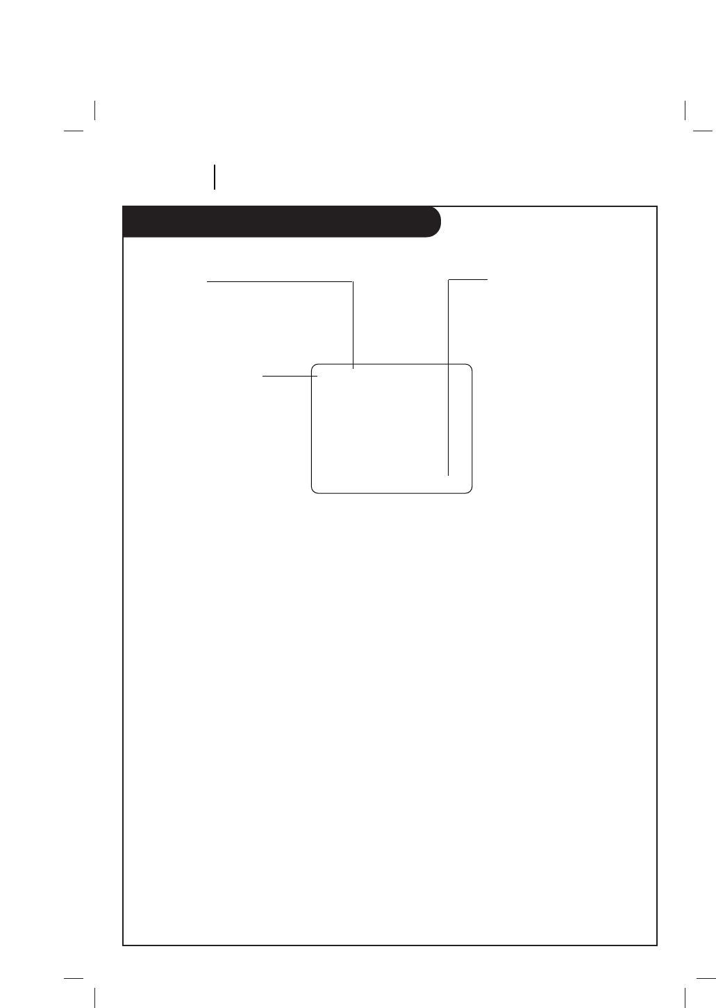
VCP Status Displays
PAGE 12 OPERATION
On-Screen displays tell you the status of the tape inserted and VCP functions.
VCP Status Display
The VCP Status Display appears on the TV when
a VCP function starts, like when you select a
different VCP mode. For example, pressing STOP
while the VCP is in PLAY mode shows STOP in
the display. Press DISPLAY on the remote at any
time (except Special Effects Playback mode;
STILL etc.) to see the Status Display.
Note:
If the VCP Status Display does not appear on
the TV screen, check the FUNCTION OSD option
on the MENU. Select ON to see the display. See
“How to using menu” section for details.
VCP Status Display Options
When the Status Display appears, press DISPLAY
repeatedly to see abbreviated displays, as fol-
lows:
1. Press DISPLAY to see Status Display.
2. Press DISPLAY to remove the displays, or
wait a few seconds and the displays are
removed.
PLAY SP
-1:35:45
Tape Speed
EP=Extended Play
LP=Long Play
SP=Standard Play
Current mode of operation
(STOP, PLAY, FF, etc.)
Real-time tape counter
– = Tape is rewound past
index mark.
-1:35:45 = Length of tape
(in time)
1 = 1 hour
35 = 35 minutes
45 = 45 seconds
Typical VCP Status Display on TV
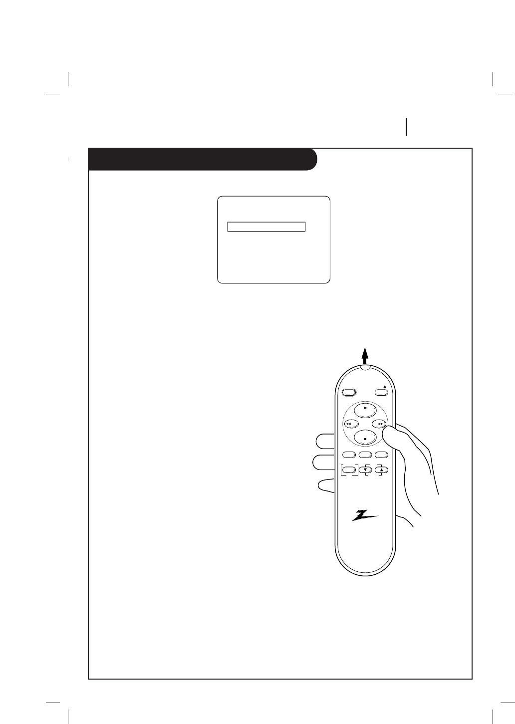
How to using menu
OPERATION PAGE 13
How to Access Menu
1 Press MENU to see menu.
2 Press the SELECT (▼/▲) to choose desired
option to be changed. Then you set desired
mode by pressing the OK button
repeatedly.
3 Press MENU to exit menu, or wait a few
minutes and the VCP returns to normal
operation.
AUTO REPEAT
If you want to play back tape repeatedly, set
AUTO REPEAT option to ON.
• When the end of the tape is reached, the
unit automatically rewinds the tape to the
beginning and repeats playback
continuously.
• If you release this function, set the AUTO
REPEAT to OFF mode.
F.(Function) OSD
Switches the on-screen display ON or OFF.
Note:
Perform menu operations with the VCP and TV
on, and tune the TV to channel 3 or 4. The VCP
must also be in the VCR mode of operation.
Press the TV/VCR button on the Remote Control
until TV/VCR indicator light appears in the
front panel.
MENU
AUTO REPEAT OFF
F.OSD ON
SELECT:
▼▲
, OK END: MENU
Point remote toward VCP
eject
power
play
stop
rew ff
tv/vcra.repeat menu
trk
select
display
ok
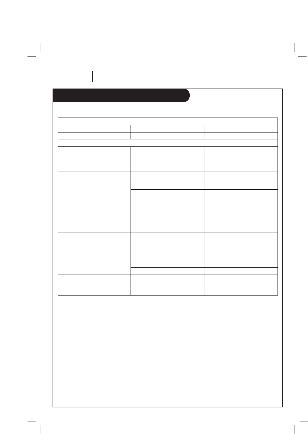
Troubleshooting and Maintenance
PAGE 14 TROUBLESHOOTING AND MAINTENANCE
Observed Condition
No power to the VCP.
The tape will not rewinds
Operating sound is audible
during playback, rewind, fast
forward. etc.
The playback picture does not
appear while the tape is running.
))
Noise appears during search and
still pictures.
Noise appears during playback.
Playback picture is blurred or
interrupted while normal TV picture
is clear.
Cassette cannot be inserted into
VCP.
Remote control does not work.
DEW Indicator is lit.
Operating Problems
Possible Cause
Power cord is not connected.
Playback Problems
Tape is already fully rewound.
Normal condition.
You are using the RF OUT jack but
the TV is not turned to the correct
video channel.
You are using the VCP audio/video
Out jacks but the TV is not set to
AUX channel or Audio/Video In
source.
Normal condition.
The tracking needs to be adjusted.
Video heads may be dirty.
The cassette is being loaded
backwards or upside down or
another cassette is already loaded.
Power cord is not connected.
Batteries are not installed or old.
Excessive condensation.
Probable Solution
Connect it.
No action is necessary.
No action is necessary.
Set the TV to either channel 3 or
channel 4.
Set the TV to AUX channel or
Audio/Video In source.
No action is necessary.
Adjust tracking.
Head cleaning is necessary.
Consult your local Zenith video
retailer.
Load cassette in direction Indicated
by arrow on cassette, or remove the
cassette that is loaded already.
Connect power cord.
Install or replace with new batteries.
Keep power on until indicator turns
off.
Before requesting Warranty service, please refer to the chart below. It may help you avoid a service call.
Maintenance
Video Head Cleaning
Your VCP automatically cleans the heads as it is
used.
After long periods of use, the video heads may
become clogged with accumulated dirt, causing
distortion (snow, streaking in picture and
horizontal pulling of picture). When this occurs,
use do-it-yourself VHS wet head cleaning cassettes
available through your Zenith video product
retailer.
Caution: Do not use dry head cleaning systems.
They may seriously damage both the video cassette
player an cassette.
Cabinet Cleaning
Clean the outside surfaces of the VCP with a soft,
lint-free cloth as required.

Specifications
SPECIFICATIONS PAGE 15
Power Requirements
Operating Voltage . . . . . . . . . . . . . . . .AC 120 V, 60Hz
DC 12 V, Neg Ground
Power consumption . . . . . . . . . . . . . . .11W (AC)
11W (DC)
Environmental Conditions
Operation . . . . . . . . . . . . . . . . . . . . .41°F to 95°F (5°C to 35°C) Temperature
35 to 80% Relative Humidity
Storage . . . . . . . . . . . . . . . . . . . . . . .-4°F to 140°F (-20°C to 60°C) Temperature
5 to 80% Relative Humidity
Physical Characteristics
Dimensions(W x H x D) . . . . . . . . . . . . .10.6 x 3.6 x 11.7 Inches(270 x 94 x 325 mm)
Weight . . . . . . . . . . . . . . . . . . . . . . .6.4 lbs (2.9 kg)
Video System
Format . . . . . . . . . . . . . . . . . . . . . . .VHS 1⁄2Inch (12.7 mm) Tape
Signal . . . . . . . . . . . . . . . . . . . . . . . .NTSC color/EIA monochrome
(525 lines/60 fields)
Output . . . . . . . . . . . . . . . . . . . . . . .1.0 Vp-p
Signal-to-Noise ratio . . . . . . . . . . . . . .≥43 dB (SP speed)
Audio Systems
Monaural . . . . . . . . . . . . . . . . . . . . . . . .1 channel standard VHS
Frequency Response . . . . . . . . . . . . . . . . .200 to 7,000 Hz (SP speed)
Signal-to-Noise ratio . . . . . . . . . . . . . . . .≥38 dB (SP speed)
Output . . . . . . . . . . . . . . . . . . . . . . . . .Minus 8 dB into ≤1,000 ohms
Note: Specifications, features, and appearance of this Video Cassette Player are subject to change
without notice. Weight and dimensions are approximate.

P/NO :
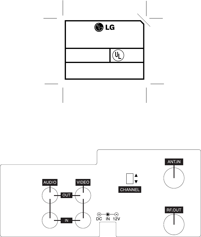
VIDEO CASSETTE PLAYER
MODEL NO.: AS106M
DC 12V 11W
MADE IN KOREA
LISTED 368K
VIDEO
CASSETTE
PLAYER
P/N3850R-M0000
®
SERIAL NO. FIX
FCC ID :BEJ9QKA2920
3
P/N 3850R-Z091C
4
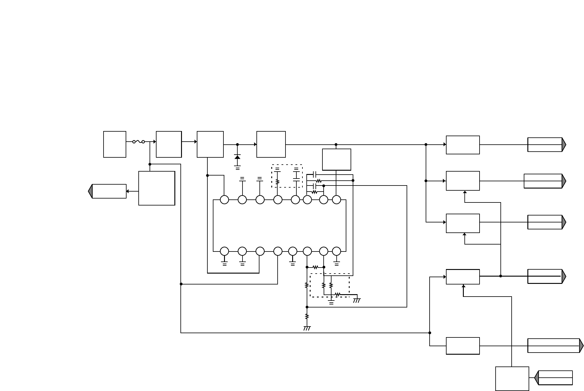
1.Power Block Diagram
TO µ-COM
5.0VA
5.0V
5.0V
12VA
L.MOTOR C.MOTOR D.MOTOR
AVCP
9V
Hi-Fi. Y/C
OSC. Hi-Fi SYSTEM
SYSTEM
µ-COM
PWR CTL
8 7 6 5 4 3 2 1
9 10 11 12 13 14 15 16
COUPLING
L101
C101
C102
SWITCHING
Q101
R101
R102
JACK
JK03
FUSE
F151
COUPLING
L102
L103
C107
OVER VOLTAGE
DEFECT
R107
R159
R160
ZD157
C104
OSC
R112
R109 R110 OVER CURRENT LIMIT
R106
R111
R103
FEED BACK
L102
L103
C107
Q156
Q155
Q158
REGULATIM
Q153
Q151
Q154
Q157
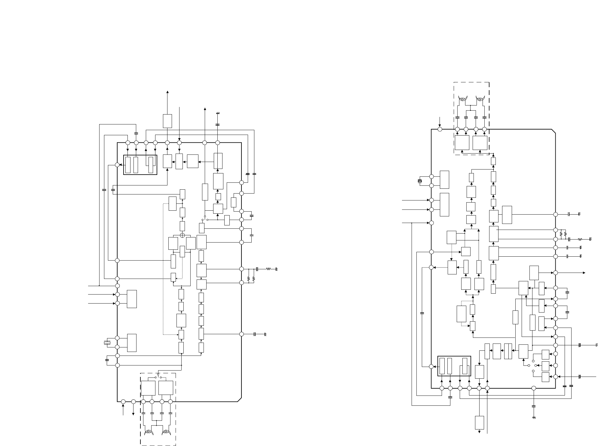
2. AVCP Block Diagram
1) PB Mode 2) REC Mode
+
+
51
42
39
44
1413
62 6963
81
86
87
89
88
84
IC301
HA118717NF
79 78
22
73 71
52
56
2126242318 19
50
60 58 35
46
V. OUT
(TO u-COM)
D-V SYNC
(FROM u-COM) System
System
Y-CCD
C-CCD
CLOCK Drive
FBC
Video ALC
LPF
REC-AMP
SP CH2
REC-AMP
SP CH1
DATA
(FROM u-COM) System
CLOCK
(FROM u-COM)
2fsc
(TO u-COM)
System
System
V.H/SW30
(FROM u-COM)
V.ENV
(TO u-COM)
System
SP CH2
SP CH1
Serial Cont
interface
X-tal
VCO/OSC
TRAP FM AGC P.EQ G.EQ D LIM Y LPF
Main
De-Empf
DEMO
S LPF
2M LPF ACC CTL Trap
fh Trap
HIFI Trap C LPF DEALY
MIX
AMP
SQUEL CH
BUFFER
CLEAR
SYNC
CLAMP
CLAMP
Sharpness
CONTROL
YNR NC
SYNC SEP C-SYNC
(TO u-COM) System
NL
De-eMPH
VCA
C.K
LPF
BDBPF
CCD LPF APC/ACC
DET
L- DET
Main
Conv2
Main
Conv1
+
+
++
1
51
52
42
39
44
46
35
31 30 28 29 21 26 24 23 18 19 50 22 20 14 13 15
LINE
VIDEO IN
35 35 6269 63 7371
81
86
87
89
88
ATT
-10dB
VIDEO
AGC
CLEAR
SYNC
V. OUT
(TO u-COM)
D-V SYNC
(TO u-COM)
System
System
System
Y-CCD
C-CCD
CLOCK Drive
6dB
AMP
FBC
Video ALC
SQUEL CH
BUFFER
ATT
-10dB
C-SYNC
(TO u-COM)
ATT
-10dB
'99.1.20 R10379BA
LPF
AGC DET
CLAMP
Y-LPF
YNR
CLAMP
SYNC
SEP
D.E.
C-LPF
SPFACC
C-LPF
NL Emph LPF
LPF
HPF VCA
TRAP
FBC
ALC
Main
Conv2
Main
Conv2
APC/ACC
DET
Main
Emph FM
MOD
REC
Trap
REC-AMP
SP CH2
REC-AMP
SP CH1
MIX
ATT
B.E
C.K
CCD
LPF
L-DET
VCD
(-4dB)
f0=1.68M
f/0DEV
Adjst
X-tal
VCO/OSC
Serial Cont
interface
DATA
(FROM u-COM) System
CLOCK
(FROM u-COM)
2fsc
(TO u-COM)
System
System
V.H/SW30
(FROM u-COM)
System
SP CH2
SP CH1
IC301
HA118717NF
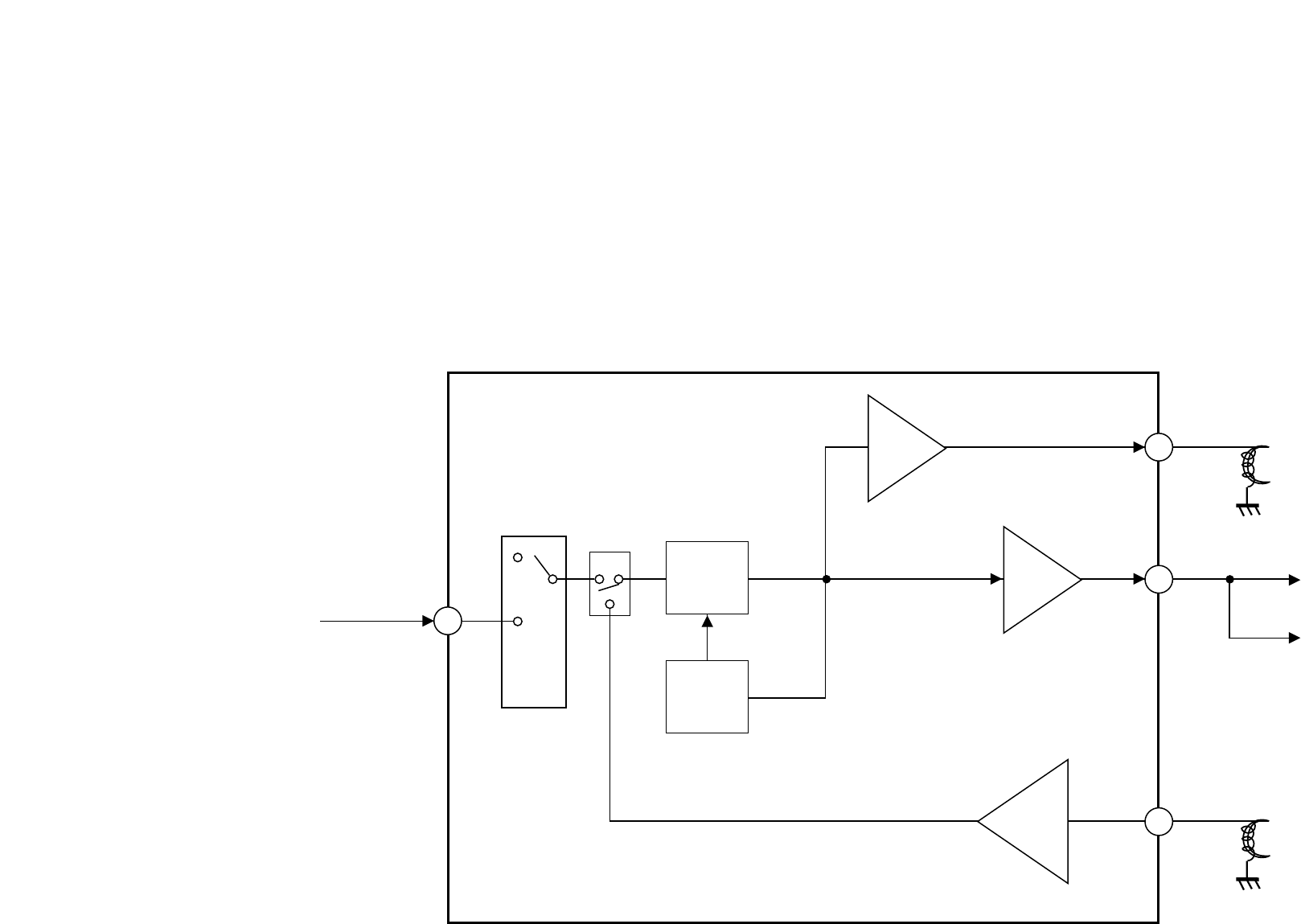
3. Audio BlocK Diagram
R/P HEAD
L.A.IN 1
IC301
HA118717NF
VCA TO LINE OUT
TO MODULATOR
A.OUT
DET
REC
AMP
AMP
PB EQ
AMP
4
11
2
R/P HEAD
'99.1.20
PB.AUDIO IN
9
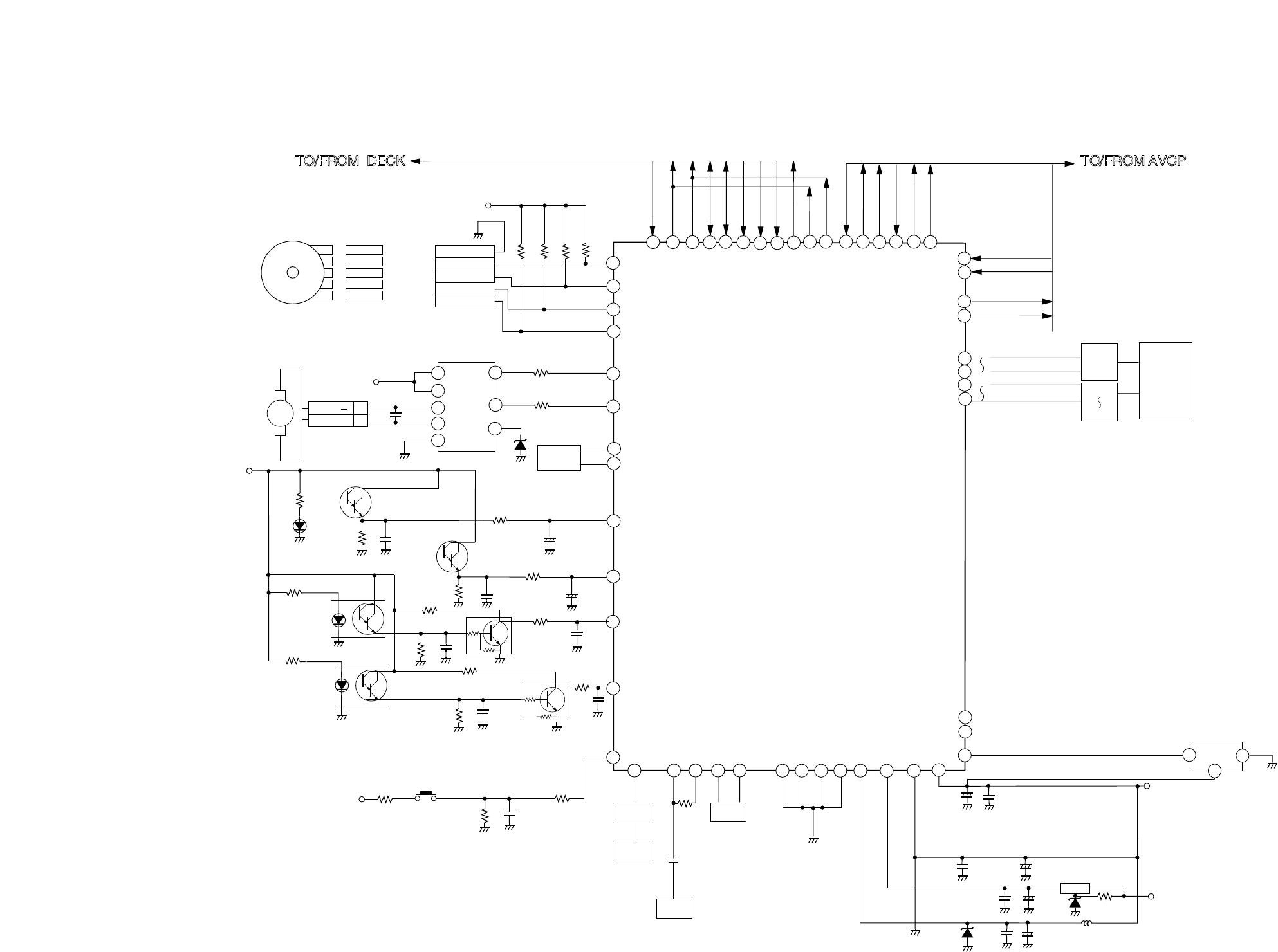
4. System Block Diagram
GND
MODE S1
MODE S2
MODE S3
MODE S4
MODE S/W
TO/FROM AVCP
T-UP REEL
T-UP END
PML01
SUP REEL
CST.SW
5.3V
CS501
5.3VA
5.3VA
ES501
R550
LD501
DECK IR LED
R553
R555
RS503
RS504
R556 C538
Q514
Q515
R558 C539
R5C5
R5C7
R560
R559
R5B3
R5B4
C534
C581
C582
R548 C552 R5C6 C500
MS501
X501
10MHz
OSC
M
LD +
LD 2
1
L/D MOTOR
12V R526
R525
5
6
4
7
8
1
10
Vcc 1
Vcc 2
OUT 1
OUT 2
GND
IN 2
IN 1
Vref
IC502
C529
ZD501
2
1
2
RESET
GND
Vcc
3
5.5VA
9V
IC504
+
+
C561
C521
C504 +C503 R516
R557 C536
SUP END
ES502
R554 C537
R544 OSC
R/C
PM902
9
3
RC901
Q510
L506
R517
R518
C518
C519
+
C506 C505 L502
TO/FROM DECK
ZD502
ZD503
Q522
CV IN
77
76
75
74
1
5
57
4
233 49 71 22
41
16
IC501
HD6473977
MODE S1
I-Limit
MODE S2
MODE S3
MODE S4
T-UP Sensor
T-UP Reel
SUP Reel
CST IN
Vss (A/D)
Vss (SERVO)
Vss (OSD)
Vss (SYSCON)
Vcc (SYSCON)
Vcc (SERVO)
CAP. PWM
CTL +
CTL -
DFG
CFG
CAP. RVS 'H'
CAP. ACCEL
DRUM ADJ.
V. ENV
V.H.SW30
C.Sync
DPG
D.V.Sync
72
73 OSC2
OSC1
53 52 50
fsc IN
fsc OUT
Dosc IN
19 LD -
LD +
20
31 32 38 40 61 80 81 12 24 87
26 39 27
CLK
DATA
90 91
25
78
DRUM PWM
42
Vcc (OSD)
3SUP Sensor
51
Dosc OUT
82 15
Vcc (A/D)
91
90
79
59
43
54
REC 'H'
OSD 'H'
C. sync (NOR)
LED
DOT
100
83
86
92
PM902
PM901
4
2
8
C573
R589
'99.1.20 R10380BB
+
C535
+

sheet 1 of 6
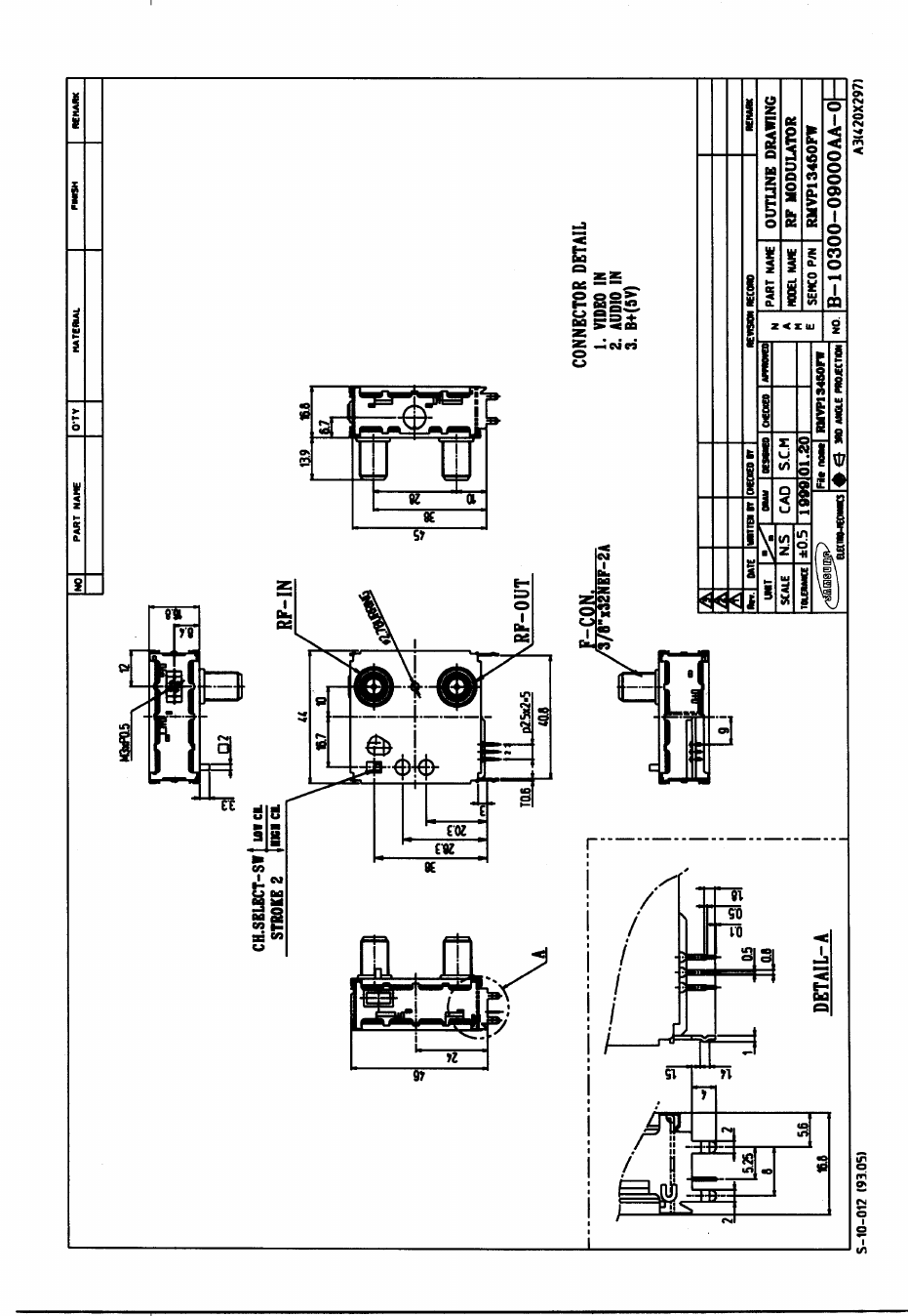
1. SCOPE
THIS SPECIFICATION OUTLINES THE PERTINENT ELECTRICAL REQUIREMENTS OF
THE RF OUTPUT MODULATOR WHICH CONVERTS THE TV VIDEO AND TV AUDIO
SIGNAL INTO THE RF SIGNAL FOR NTSC M COLOR TELEVISION.
2. GENERAL SPECIFICATIONS
2-1. OUTPUT CHANNEL IS CHANNEL 3CH of 4CH
PRESET CHANNEL: 4CH(67.25MHz)
2-2 SUPPLY VOLTAGE B+ : 5 ¡¾ 0.25V DC
2-3. CONSUMPTION CURRENT 50mA MAX
2-4. OPERATION CONDITIONS TEMPERATURE 0 ~ 60¡É
FOR GUARANTEE
2-5. STORAGE CONDITIONS TEMPERATURE -10 ~ 70¡É
2-6. SHAPE AND PHYSICAL COMPLIES WITH ATTACHED OUTLINE
CONDITION DIMENSION DRAWING.
3. TEST CONDITIONS
3-1. TESTING AMBIENT CONDITIONS
DEFINED AS TEMPERATURE OF 25¡¾3¡É AND HUMIDITY OF 65¡¾5% RH.
NOTE: THAT TEMPERATURE OF 15 ~ 30¡É AND HUMIDITY OF 45 ~ 85% RH
MAY BE REGARDED AS STANDARD.
3-2. DRIVING POWER
B+ : 5 ¡¾ 0.25V DC
3-3. UNIT SETTING CONDITIONS
1) PICTURE --- APPLY 77% MODULATION COLOR BAR SIGNAL 1Vp-p,
AND SET MODULATION AND V/S RATIO STANDARD VALUES.
NOTE) MODULATION SETTING - WHITE SIGNAL, 1Vp-p : V/S = 10/4
2) SOUND --- SET 1.1Vp-p (-6dBs)OF SINE WAVE 1KHz.
SPECIFICATIONS
RMVP13450FW
SAMSUNG ELECTRO-MECHANICS CO.,LTD.
sheet 2 of 6
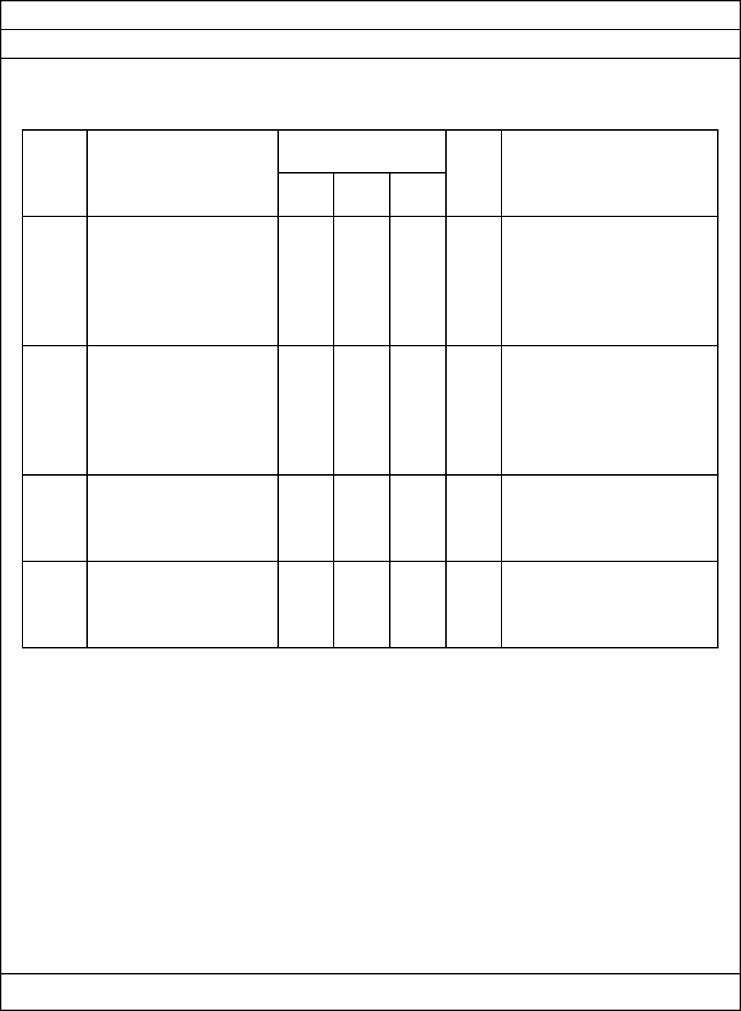
4. ELECTRICAL PERFORMANCE
4-1. VIDEO SYSTEM CHARACTERISTICS
PARAMETER UNIT REMARK
MIN TYP MAX
4-1-1 INPUT IMPEDANCE 0.7 1.0 1.3 K§Ù MEASURE AT 0 ~ 4.2MHz
4-1-2 MODULATION 72 77 82 %
4-1-3 AMPLITUDE FREQUENCY -3 3 dB MEASURE MULTIBURST OR
RESPONSE SWEEP RF OUTPUT OVER
A RANGE OF 0.75 ~ 4.2MHz
WITH 1MHz AS REFERENCE.
4-1-4 DIFFERENTIAL GAIN -8 8 % MEASURE AT 10% ~ 90% OF
APL.
4-1-5 DIFFERENTIAL PHASE -10 10 DEG MEASURE AT 10% ~ 90% OF
APL.
4-1-6 MODULATION VARIATION -3 3 % MEASURE MODULATION
WITH RESPECT TO APL VARIATION OVER A RANGE
OF 10~90% APL WITH
RESPECT TO 50% APL.
4-1-7 S/N 45 dB MEASURE WITH RESPECT TO
STANDARD DEMODULATOR
OUTPUT.
4-1-8 V/S RATIO 6.7 7.3 APPLY STAIRSTEP INPUT
/ 7/3 / SIGNAL 1Vp-p V/S=7/3
3.3 2.7 NEGATIVE SYNCHRO SIGNAL
4-1-8 920KHz BEAT 58 VIDEO INPUT SIGNAL:
0.4Vp-p
3.58MHz SINE WAVE
SPECIFICATIONS
RMVP13450FW
SPECIFICATION
SAMSUNG ELECTRO-MECHANICS CO.,LTD.
sheet 3 of 6
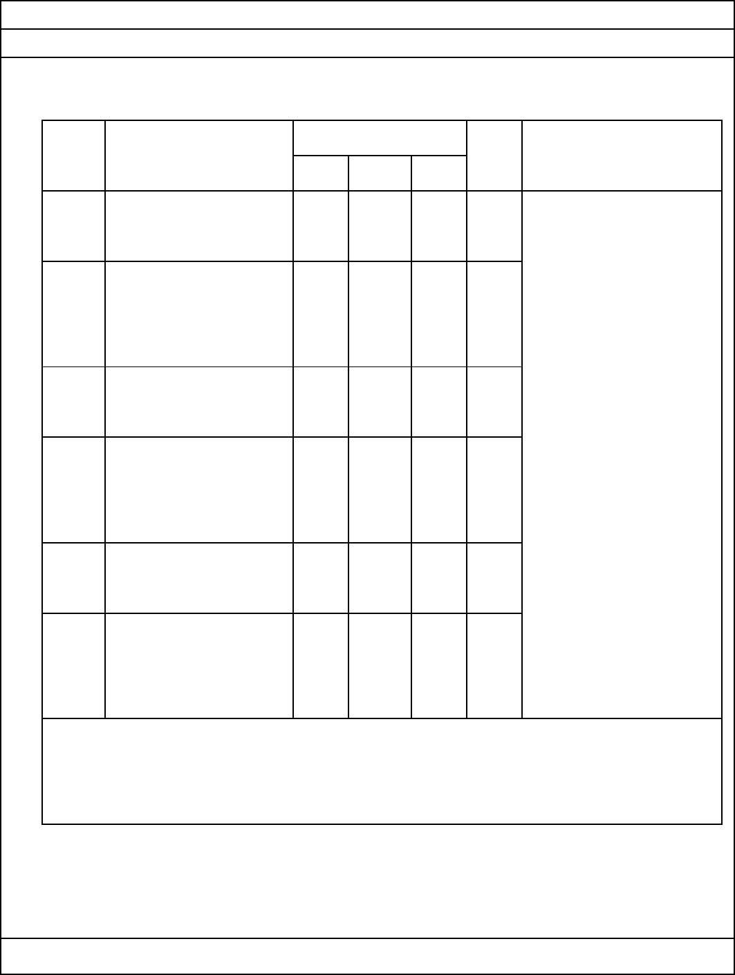
4-2. SOUND SYSTEM CHARACTERISTICS
PARAMETER SPECIFICATION UNIT REMARK
MIN TYP MAX
4-2-1 INPUT IMPEDANCE 10 K§Ù MEASURE AT 0.1 ~ 10Khz
4-2-2 MODULATION 65 80 95 % 100% = ¡¾25KHz
4-2-3 AMPLITUDE FREQUENCY -3 3 dB MEASURE DEVIATION FROM
RESPONSE THEORETICAL VALUE OF
75usec PRE-EMPHASIS
CHARACTER OVER A RANGE
OF 100Hz TO 10KHz WITH
1KHz AS REFERENCE.
4-2-4 DISTORTION FACTOR 2.5 % SOUND INPUT : 1.1Vp-p
4-2-5 S/N 45 dB
4-3. OUTPUT SYSTEM CHARACTERISTICS Fp: 3CH(61.25MHz),4CH(67.25MHz)
PARAMETER SPECIFICATION UNIT REMARK
MIN TYP MAX
4-3-1 VIDEO CARRIER -100 Fp 100 KHz TEST AT 25¡É
FREQUENCY TEMPERATURE AND 65%RH
Fp : VIDEO CARRIER
4-3-2 SOUND CARRIER -10 Fs -10 KHz FREQUENCY
FREQUENCY Fs : SOUND CARRIER
FREQUENCY (4.5MHz)
4-3-3 VIDEO OUTPUT LEVEL 63.5 66.5 69.5 dBu DIFFERENCE BETWEEN VIDEO
4-3-4 V/S RATIO 13 16 19 dB AND SOUND OUTPUT LEVEL
(SOUND IS UNMODULATION)
4-3-5 OUTPUT TERMINAL -30 dB MEASUREMENT TAKEN UNDER
SPURIOUS RESPONSE FCC STANDARD PROCEDURE
FOR 0 ~ 1GHz.
4-3-6 SPURIOUS RESPONSE -60 dB BETWEEN fp AND fs
WITHIN BANDWIDTH
SPECIFICATIONS
RMVP13450FW
SAMSUNG ELECTRO-MECHANICS CO.,LTD.
sheet 4 of 6
4-4. OFF THROUGH SWITCH CHARACTERISTICS
PARAMETER UNIT REMARK
MIN TYP MAX
4-4-1 INSERTION LOSS ANT IN ¡æ RF OUT
B+ OFF
3 dB 55MHz ~ 890MHz
4-4-2 V.S.W.R
4 ANT IN
4 RF OUT
4-4-3 ANT LEAKAGE 9.5 dBu 75¥Ø TERMINATE.
4-4-4 ISOLATION 60 dB ANT IN ¡æ ANT OUT
61 ~ 72MHz
SPECIFICATIONS
RMVP13450FW
SPECIFICATION
SAMSUNG ELECTRO-MECHANICS CO.,LTD.
sheet 5 of 6
4-5. THERMAL CHARACTERISTICS
PARAMETER UNIT REMARK
MIN TYP MAX
4-5-1 THERMAL STABILITY IN -10 INITIAL 10 % -. MEASURE VARIATION
VIDEO MODULATION VALUE WITH RESPECT TO
4-5-2 THERMAL STABILITY IN INITIAL INITIAL VALUE AT
VIDEO CARRIER -100 VALUE 100 KHz 0 ~ 60¡É
FREQUENCY
4-5-3 THERMAL STABILITY IN -10 INITIAL 10 %
SOUND MODULATION VALUE
4-5-4 THERMAL STABILITY IN INITIAL
SOUND CARRIER -15 VALUE 15 KHz
FREQUENCY
4-5-5 THERMAL STABILITY IN -4 INITIAL 4 dB
VIDEO CARRIER LEVEL VALUE
4-5-6 THERMAL STABILITY IN INITIAL
SOUND OUTPUT LEVEL -4 VALUE 4 dB
DIFFERENCE
UNLESS OTHERWISE SPECIFIED, THE ABOUT TEST SHOULD BE CARRIED UNDER CONDITION
OF +25¡É, 1HR (INITIAL VALUE) ¡æ +0¡É, 1HR ¡æ +25¡É, 1HR ¡æ +60¡É, 1HR.
HUMIDITY 45 ~ 80% RH.
SPECIFICATIONS
RMVP13450FW
SPECIFICATION
SAMSUNG ELECTRO-MECHANICS CO.,LTD.

sheet 6 of 6
5. ENVIRONMENT TESTS
PARAMETER SPECIFICATION UNIT REMARK
5-1 HEAT RESISTANCE
STRONG TEST
1. VIDEO MODULATION INITIAL ¡¾ 10 % A. ENVIRONMENTAL CONDITIONS
2. AUDIO MODULATION INITIAL ¡¾ 25 % TEMPERATURE: 60¡¾3¡É
3. VIDEO CARRIER INITIAL ¡¾ 500 KHz B. POWER SUPPLY: OFF
FREQUENCY C. MEASUREMENT: 96HOUR
4. AUDIO CARRIER INITIAL ¡¾ 25 KHz D. AFTER USING THE ABOVE
FREQUENCY CONDITIONS, THE TESTED
5. VIDEO OUTPUT INITIAL ¡¾ 4 dB MODULATION IS LEFT FOR
LEVEL 2.0 HOUR AT NORMAL ROOM
6. AUDIO OUTPUT INITIAL ¡¾ 4 dB TEMPERATURE
LEVEL E. HUMIDITY: 40% ~ 45%RH
5-2 COLD TEST SAME AS IN ITEM A. ENVIRONMENTAL CONDITIONS
5-1 TEMPERATURE: -20¡¾3¡É
B. C,D,E SAME AS B,C,D,E
ITEM 5-1
5-3 HUMIDITY RESISTANCE SAME AS IN ITEM A. ENVIRONMENTAL CONDITIONS
STORAGE TEST 5-1 TEMPERATURE: 40¡¾3¡É
B. POWER SUPPLY: ON
C,D. SAME AS ITEM 5-1
E. HUMIDITY: 90% ~ 95%RH
5-4 VIBRATION THE RATED PERFO- BEFORE MEASUREMENT OF PERFORMANCES,
RMANCE SHALL BE THE VIBRATION TEST FIXTURE IS USED
SATISFIED. TO GIVE THE MODULATOR VIBRATION
WITH TOTAL AMPLITUDE OF 2mm FREQUE-
NCY RANGING FROM 7Hz TO 30Hz,
ONCE PERMINUTE CONSECUTIVELY FOR
3 MINUTES.
IN EACH OF THREE DIRESTIONS X,Y,Z
SPECIFICATIONS
RMVP13450FW
SAMSUNG ELECTRO-MECHANICS CO.,LTD.