LG Electronics USA 9QKE00711 HD Cable DVR STB User Manual 1
LG Electronics USA HD Cable DVR STB 1
UserManual.wiki
>
LG Electronics USA
>
9QKE00711 User Manual
manual
Navigation menu
Upload a User Manual
Namespaces
Wiki Guide
HTML
PDF
Info
Views
User Manual
Discussion / Help
Navigation
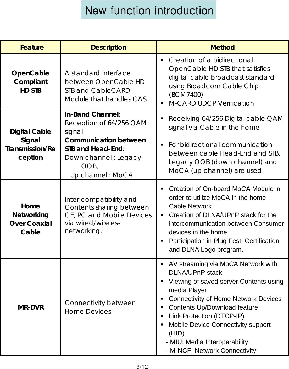
![Front & Rear Panel Specification [ Front Panel Layout ][ Rear Panel Layout ]2/12 Cable InCable Out(loop-through)Ethernet S-Video CompositeComponentSPDIF(Optical)HDMIAC AccessoryOutletAudio (L/R)USBiEEE-1394External SATAAC Inlet](https://usermanual.wiki/LG-Electronics-USA/9QKE00711/User-Guide-875395-Page-2.png)
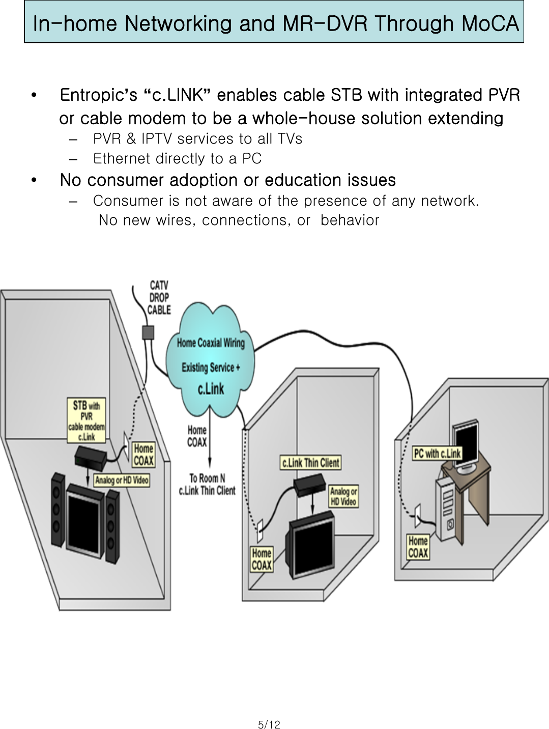
![MPEG-2 StreamMultiplexerCombine/SplitterOOBModulatorMPEGStreamSpooler DigitalModulator Up-converterCable Head-end (Signal Lab)PSIPServer(In-band)AV ChannelPSIP TableCableCARDPC ECBEthernet c.Link[64/256 QAM Channel] ♦For the A/V Channel Tuning test, the existing QAM signal set up at the AV Business Dept. will be used.♦Verify A/V output and channel change with basic channel tuning.[OOB Channel]♦Produce random signals from the OOB Modulator and verify Tuning status.[MoCA Channel]♦Verify MoCA Network communication with Ethernet connection between the PC and ECB.[CableCARD]♦Verify CableCARD Operation.[Home Networking] ♦Verify connectivity between STBs (Server/Client). ♦Verify Media Interoperability and Network Connectivity.LGE Native UI AppOOB SI TableBroadcom STB APILG STB APIOperational ConceptHome Networking¾QAM/IP STB Operational Concept6/12](https://usermanual.wiki/LG-Electronics-USA/9QKE00711/User-Guide-875395-Page-8.png)