LG Electronics USA ANWL100W WIRELESS MEDIA BOX User Manual G User s manual
LG Electronics USA WIRELESS MEDIA BOX G User s manual
UserManual.wiki
>
LG Electronics USA
>
ANWL100W User Manual
Users Manual
Navigation menu
Upload a User Manual
Namespaces
Wiki Guide
HTML
PDF
Info
Views
User Manual
Discussion / Help
Navigation
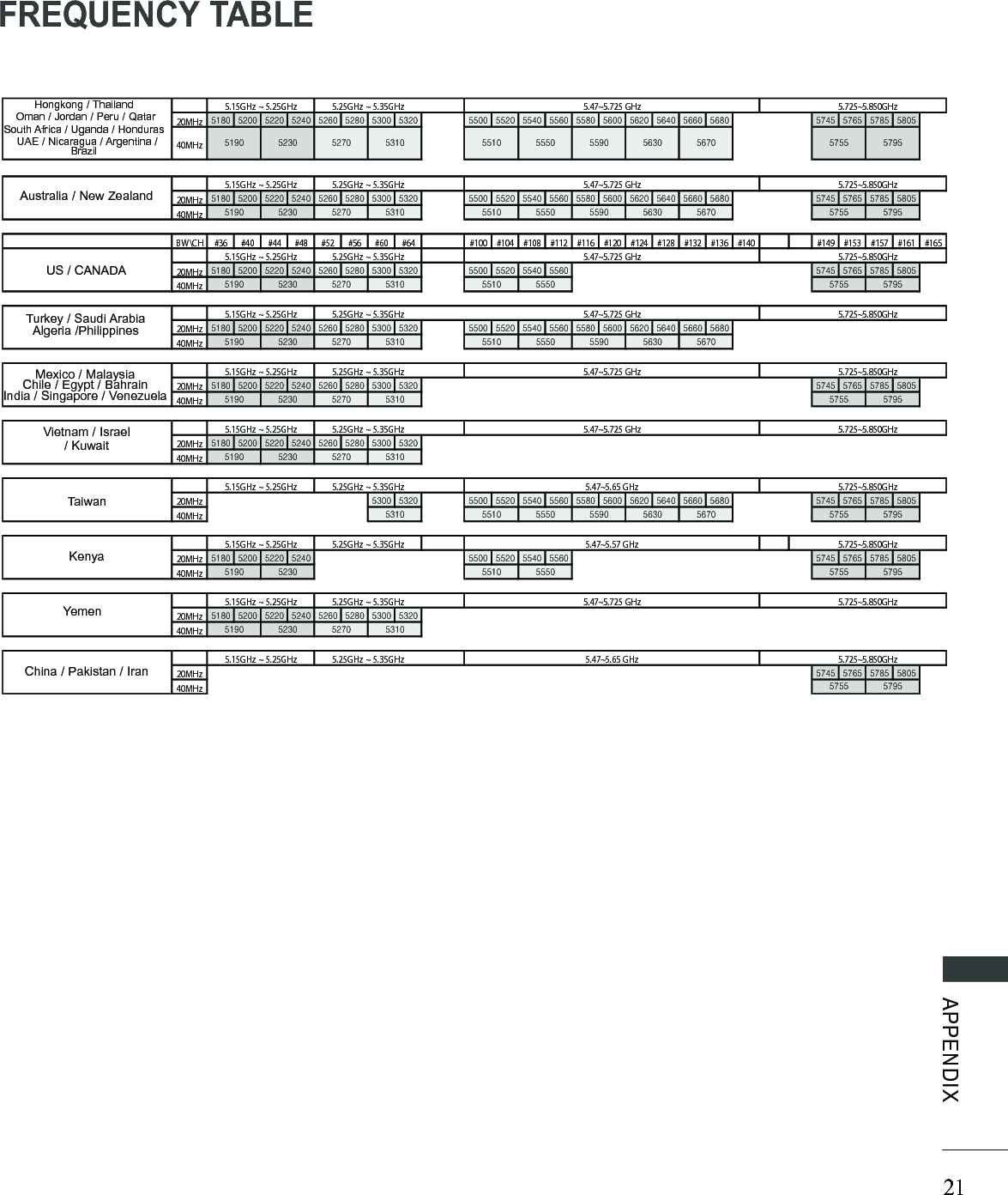
![20APPENDIXAPPENDIXItems U-NII-I U-NII-II U-NII-II extended U-NII-IIIFrequency range [GHz] 5.15~5.25 5.25~5.35 5.47~5.725 5.725~5.825Transmission OFDM OFDM OFDM OFDMRF Output Power (Max.) [dBm] 15 15 15 15Antenna Gain (Max.) [dBi] 3.5 3.5 3.5 3.5Channel Table [MHz](Center frequency) Depends on the country region (Please see the Frequency Table)Channel units 2 ~ 11Depends on the country region (Please see the Frequency Table)■ Band channel used by the country could be different.Wireless Media BoxWireless Ready DongleItems U-NII-I U-NII-II U-NII-II extended U-NII-IIIFrequency range [GHz] 5.15~5.25 5.25~5.35 5.47~5.725 5.725~5.825Transmission OFDM OFDM OFDM OFDMRF Output Power (Max.) [dBm] 16 16 16 16Antenna Gain (Max.) [dBi] 3.5 3.5 3.5 3.5Channel Table [MHz](Center frequency) Depends on the country region (Please see the Frequency Table)Channel units 2 ~ 11Depends on the country region (Please see the Frequency Table)RF SPECIFICATIONS](https://usermanual.wiki/LG-Electronics-USA/ANWL100W/User-Guide-1232297-Page-21.png)