LG Electronics USA ANWL100W WIRELESS MEDIA BOX User Manual G User s manual
LG Electronics USA WIRELESS MEDIA BOX G User s manual
Users Manual

Order Number : GETEC-C1-10-025 FCC Part 15 subpart B
Test Report Number : GETEC-E3-10-006 Page 1 / 1
EUT Type: Wireless Media Box
FCC ID.: BEJANWL100W
APPENDIX G
: USER’S MANUAL

www.lge.com
OWNER’S MANUAL
WIRELESS MEDIA BOX
Please read this manual carefully before operating
your set and retain it for future reference.

2
CONTENTS
CONTENTS
Manufactured under license from Dolby Laboratories.
"Dolby" and the double-D s of Dolby Laboratories.
Except for USA
PREPARATION
Accessories .........................................................3
Front panel controls ............................................4
BACK PANEL INFORMATION ............................5
Side panel INFORMATION .................................5
Wireless Ready Dongle ......................................6
Connecting to the TV. ..........................................6
Attaching the Wireless Ready Dongle ................7
Back Cover for Wire Arrangement ......................8
Connection of 12 V AC/DC Adapter ....................8
Optimal Installation Location of Wireless Media
Box ......................................................................9
Attaching the IR blaster .....................................10
Optimal location of external device with IR
Blaster installed .................................................10
EXTERNAL EQUIPMENT SETUP
Connecting with a Component cable ................11
Connecting with an HDMI cable .......................12
Connecting with an HDMI to DVI cable ............13
Connecting with RCA cable ..............................14
Digital Audio Out Setup .....................................15
Connecting with RGB ........................................15
Supported Display Resolution ...........................16
WATCHING TV / PROGRAM CONTROL
Turning on the Wireless Media box ..................17
Input list .............................................................18
IR Blaster Setup ................................................18
APPENDIX
IR Code List ......................................................19
RF Specifications ..............................................20
Frequency Table ................................................21
Product Specifications .......................................22
Troubleshooting .................................................22
3
PREPARATION
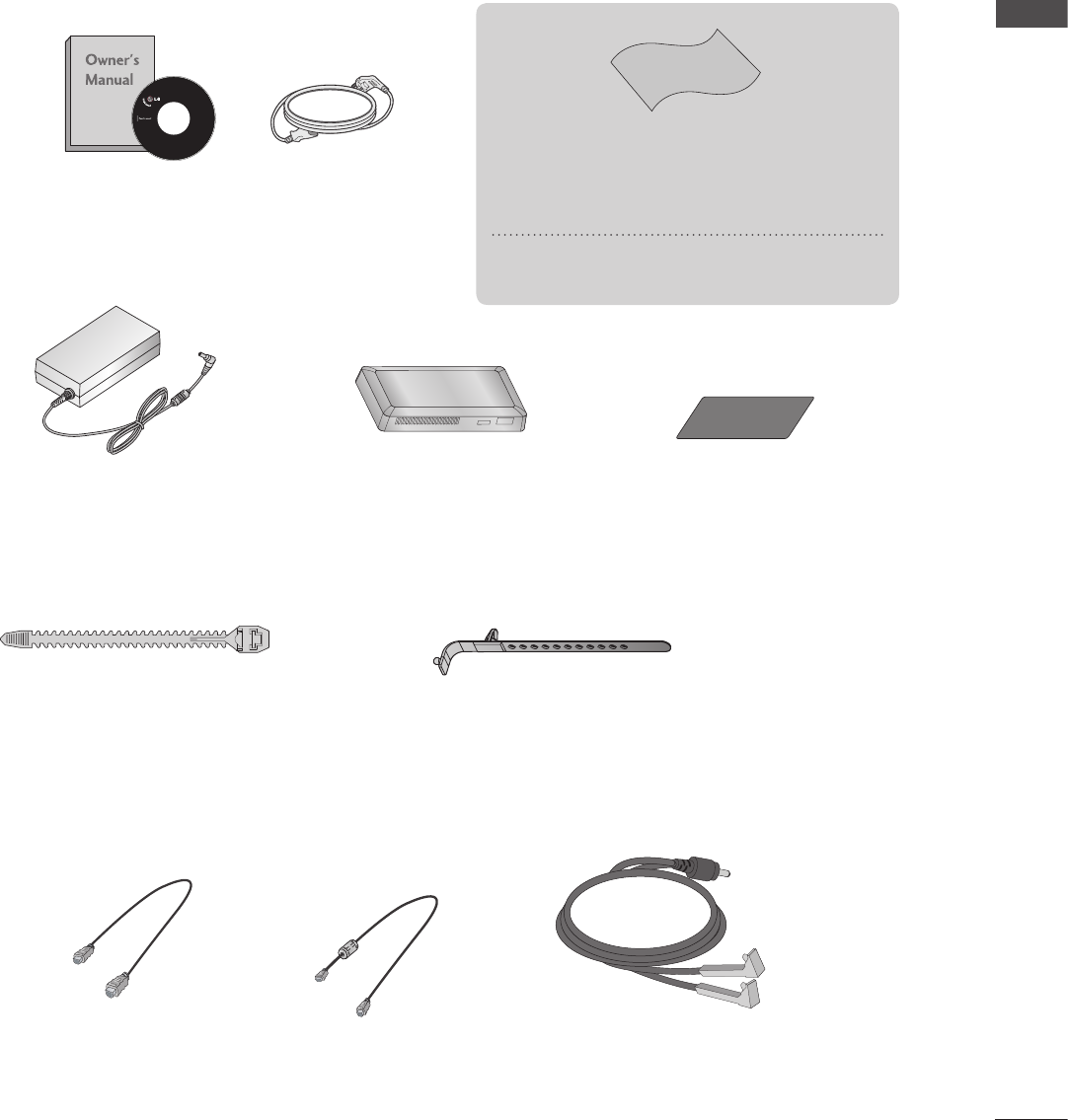
Ensure that the following accessories are included with your Wireless Media Box. If an accessory is
missing, please contact the dealer where you purchased the set.
■ Image shown may differ slightly from your device.
Owner’s Manual Power Cord
12V AC/DC Adapter
20 Pin Cable
(Power/Control)
HDMI Cable
IR Blaster Cable
X 2EA
Wireless Ready Dongle Velcro
Cable Holder
X 2EA
Cable Management Clip
Polishing Cloth
* Lightly wipe any stains or fingerprints
on the surface of the Wireless Media Box
with the polishing cloth.
Do not use excessive force. This may
cause scratching or discolouration.
PREPARATION
ACCESSORIES
4
PREPARATION
PREPARATION
* ID Label of Wireless Media Box is located at the bottom of Wireless Media Box.
IN 4
AV1 AV2 COM1 COM2 RGB WIRELESS
A
R
L(MONO)
AUDIO
VIDEO
B
1
2
SERVICE ONLY
3
RGB IN (PC)
AUDIO IN
RGB/DVI
SERVICE ONLY
IR BLASTER
A
B
COMPONENT / AV IN 1
COMPONENT / AV IN 2
R
L(MONO)
AUDIO
VIDEO
OPTICAL DIGITAL
AUDIO OUT
DC IN 12V
HDMI1 HDMI2 HDMI3 HDMI4
LRLR
/ DVI IN
12 3 4
1
2
3
4
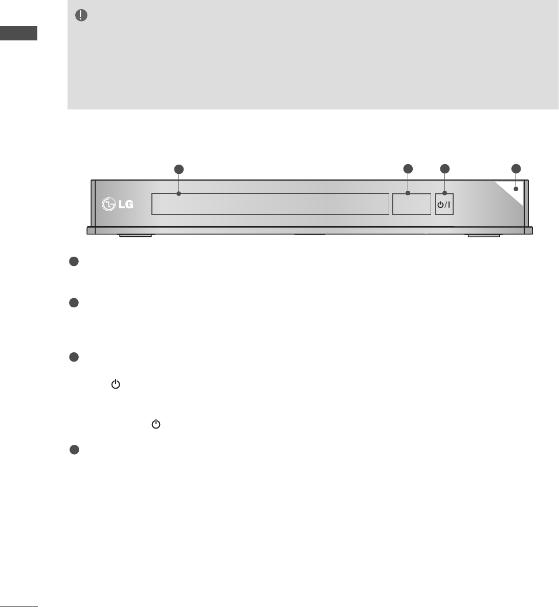
Input Source Indicator & INPUT touch button
Select the input source by touching.
Wireless Connection Indicator
It will flash when trying to connect to a wireless network and be turned on when
connected.
POWER touch button
Turn the Wireless Media Box on or off by touching.
If the
(Power) button of the Wireless Media Box is not turned on, the Wireless
Media Box will not be turned on even when turn on the power of the TV.
If the Wireless Media Box is not turned on even after turning the power of the TV
on, check the
(Power) button of the Wireless Media Box.
Power/Standby Indicator
Illuminates red in standby mode.
Illuminates white when the Wireless Media Box is switched on.
■ Image shown may differ slightly from your device.
NOTE
► This product is only for home use.
► Do not use this product in medical institutions or near medical devices. It may cause some med-
ical devices to malfunction.
► Wireless device used to this instrument could be set up and used only to this instrument.
►When using the external device connected to the Wireless Media Box, some functions of the TV
menu many not work.
FRONT PANEL CONTROLS
5
PREPARATION
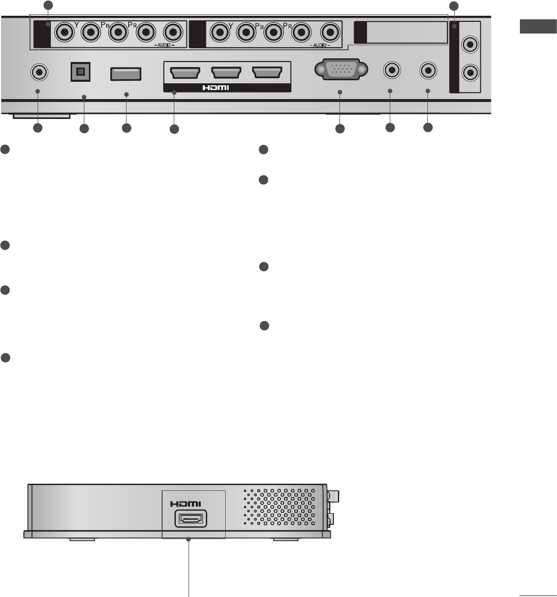
Component Input
Connect a component video/audio device to
these jacks.
Audio/Video Input(AV1/2)
Connect audio/video output from an external
device to these jacks.
IR Blaster
Controls external equipment.
DC IN 12 V Power Cord Socket
This Wireless Media Box operates on 12 V
DC power. Only use a power converter that
the device was designed to use.
Optical Digital Audio Out
Optical digital audio output for use with
amps.
Note: In standby mode, this port doesn’t
work.
SERVICE ONLY PORT
HDMI/DVI IN Input
Digital Connection. Supports HD video and
Digital audio. Doesn’t support 480i. Accepts
DVI video using an adapter or HDMI to DVI
cable (not included).
RGB IN (PC) Input
Analog PC Connection. Uses a D-sub 15 pin
cable (VGA cable).
AUDIO IN (RGB/DVI) Input
Connect the audio from an external device.
1
2
3
7
8
5
6
■ Image shown may differ slightly from your device.
4
IN 4
AV1 AV2 COM1 COM2 RGB WIRELESS
A
R
L(MONO)
AUDIO
VIDEO
B
1
2
SERVICE ONLY
3
RGB IN (PC)
AUDIO IN
RGB/DVI
SERVICE ONLY
IR BLASTER
A
B
COMPONENT / AV IN 1
COMPONENT / AV IN 2
R
L(MONO)
AUDIO
VIDEO
OPTICAL DIGITAL
AUDIO OUT
DC IN 12V
HDMI1 HDMI2 HDMI3 HDMI4
LRLR
/ DVI IN
12
35678
45
HDMI IN 4
Digital Connection.
Supports HD video and Digital audio.
Doesn’t support 480i and 576i.
IN 4
AV1 AV2 COM1 COM2 RGB WIRELESS
A
R
L(MONO)
AUDIO
VIDEO
B
1
2
SERVICE ONLY
3
RGB IN (PC)
AUDIO IN
RGB/DVI
SERVICE ONLY
IR BLASTER
A
B
COMPONENT / AV IN 1
COMPONENT / AV IN 2
R
L(MONO)
AUDIO
VIDEO
OPTICAL DIGITAL
AUDIO OUT
DC IN 12V
HDMI1 HDMI2 HDMI3 HDMI4
LRLR
/ DVI IN
■ Image shown may differ slightly from your device.
BACK PANEL INFORMATION
SIDE PANEL INFORMATION
6
PREPARATION
PREPARATION
1
2
■ Image shown may differ slightly from your device.
OUT
WIRELESS
CONTROL
2
1
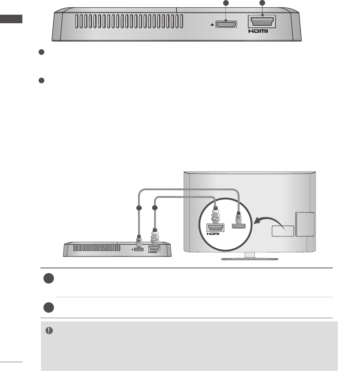
1 Use the provided 20 pin cable (power/control) to connect to the wireless control port of the
Wireless Ready Dongle and the wireless control port on the TV.
2Now connect the HDMI to both the TV and the Wireless Ready Dongle.
OUT
WIRELESS
CONTROL
IN
WIRELESS
CONTROL
12
■ Image shown may differ slightly from your device.
NOTE
►Install the Wireless Ready Dongle with the power of the TV turned off.
►Use the wireless control jack and 20 pin cable only for connecting the Wireless Ready TV and
Wireless Ready Dongle. When used for other purposes, it can cause an error or damage to the
product.
Wireless Control Port
This port is used to send and receive commands between the TV and the Wireless Media Box.
HDMI Out Port
This port sends the audio and video received from the Wireless Media Box to the TV.
WIRELESS READY DONGLE
CONNECTING TO THE TV.
7
PREPARATION
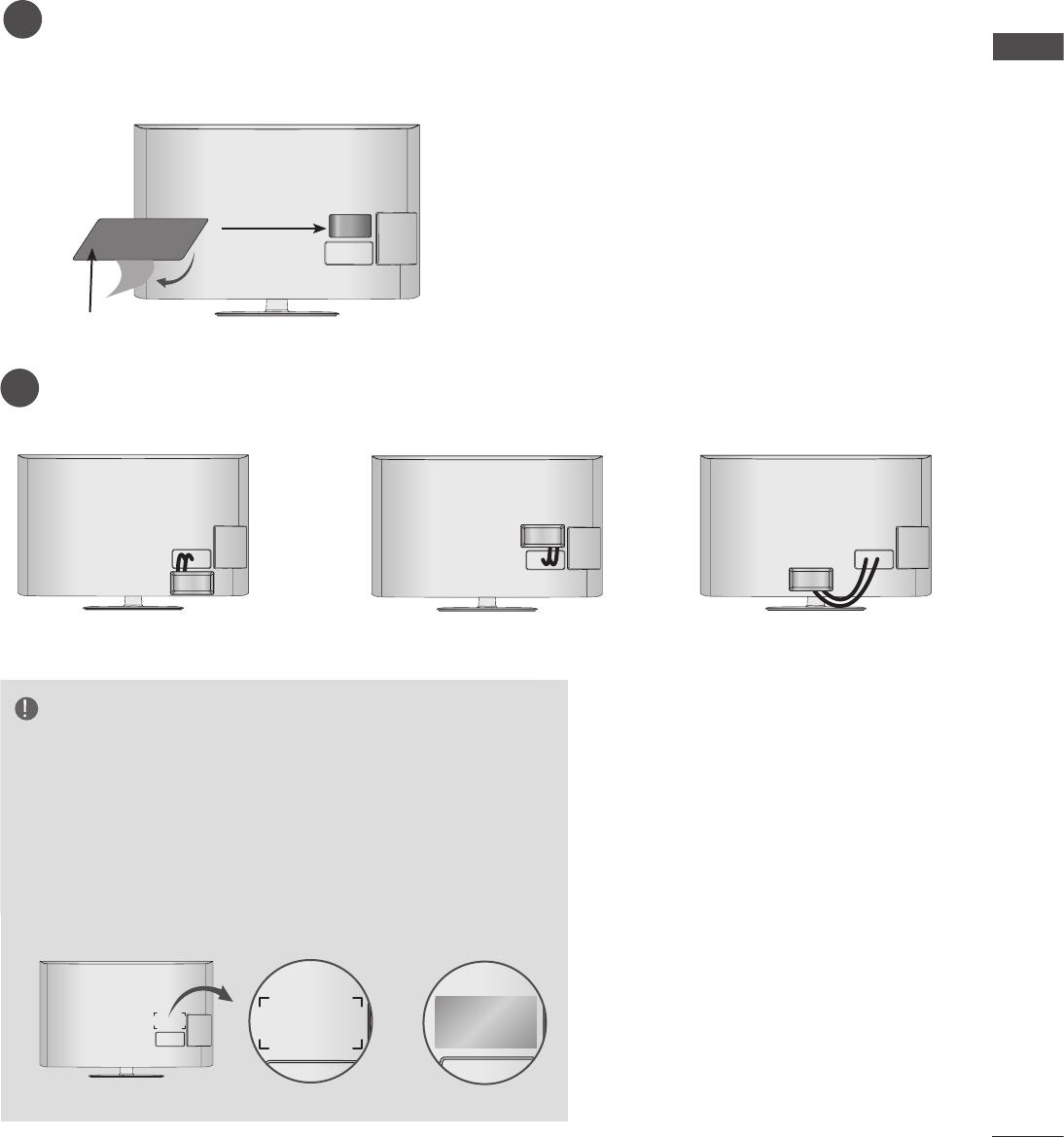
■ The Wireless Ready Dongle can be attached to the back of the TV with the included materials.
Remove the protective paper from the included Velcro pad and attach it to the TV as shown. It
does not have to be in same position, but should be close to the TV's inputs. The TV will have
a recommended location engraved on the TV.
1
Now place the Wireless Ready Dongle onto the Velcro pad.
2
or
Velcro
or
NOTE
►The attaching location on the Wireless Ready Dongle
can differ by model. Check the engraving on the back
cover and attach the cable according to the engraving.
►Clean the part where the magic tape (Velcro) is
attached using the supplied brush and attach the part
by pressing the area evenly for 1 minute. After about
10 minutes attach the wireless dongle firmly.
• Engraving
or
ATTACHING THE WIRELESS READY DONGLE
8
PREPARATION
PREPARATION
■ Image shown may differ slightly from your device.
3Now install the Cable Management Clip
which will attach to the back of the TV.
NOTE: The Cable Management Clip attach-
ment location on the TV can differ by
model.
NOTE
►Do not use the Cable Management Clip to
lift the TV. If the TV is dropped, you may be
injured or the TV may be damaged.
Connect the cables as necessary.
(Refer to the p.6 to 7.)
1
After connecting the cables, bundle
the cables and install the Cable Holder as
shown.
2
Cable Holder
Cable Management Clip
A
R
L(MONO)
AUDIO
VIDEO
B
1
2
SERVICE ONLY
3
RGB IN (PC)
AUDIO IN
RGB/DVI
SERVICE ONLY
IR BLASTER
A
B
COMPONENT / AV IN 1
COMPONENT / AV IN 2
R
L(MONO)
AUDIO
VIDEO
OPTICAL DIGITAL
AUDIO OUT
DC IN 12V
LR
LR
/ DVI IN
1
2
1
2
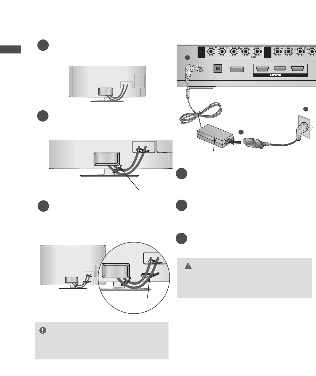
3
Connect the 12 V AC/DC adapter plug to
the DC IN 12V input jack on the Wireless
Media Box.
Connect the power cord to the 12 V AC/DC
adapter first, then plug the power cord into
the wall power outlet.
Use only power supplies listed in the user
instuction.
CAUTION
►Please be sure to connect the TV to the AC/
DC power adapter before connecting the
TV's power plug to a wall power outlet.
■ Image shown may differ slightly from your device.
3
12V AC/DC Adapter
BACK COVER FOR WIRE
ARRANGEMENT
CONNECTION OF 12 V AC/
DC ADAPTER
9
PREPARATION
■ Keep the media box near the wireless ready don-
gle (TV) within 15 m (49 feet).
* Maximum receiving distance may differ depend-
ing on the building structure.
■ Do not locate the media box and wireless ready
dongle between walls.
■ If there is a large metallic object between the
media box and wireless ready dongle, the trans-
mission performance may be decreased.
■ Avoid to putting the media box on the top of the
hot objects (such as heater, set-top box or blueray
player).
■ Make sure that the distance between the media
box and wireless ready dongle is more than 0.3 m
(1 feet).
■ If there are more than four devices using the 5
GHz band in your house, you may experience
poor picture quality or a long connection time.
* There are three kinds of 5 GHz products.
- 5.8 GHz codeless phone
- Dual band(2.4 GHz / 5 GHz) wireless LAN
- Wireless AV transmitter using Amimon chipset.
■ In this case, proceed as follows.
Move the 5 GHz products away at least 5 m (16
feet) from the wireless ready dongle.
Please set your wireless LAN to 2.4 GHz band-
width (channel 1~11).
- Please refer the manual of your router for detail
information.
- If it is not possible to change the channel,
please move the router away from the wireless
ready dongle.
Minimum 5 m
(16 feet)
Wireless Media Box
Wireless units
of 5 GHz band
0.3 m to 15 m
(1 feet to 49 feet)
OPTIMAL INSTALLATION LOCATION OF WIRELESS
MEDIA BOX
10
PREPARATION
PREPARATION
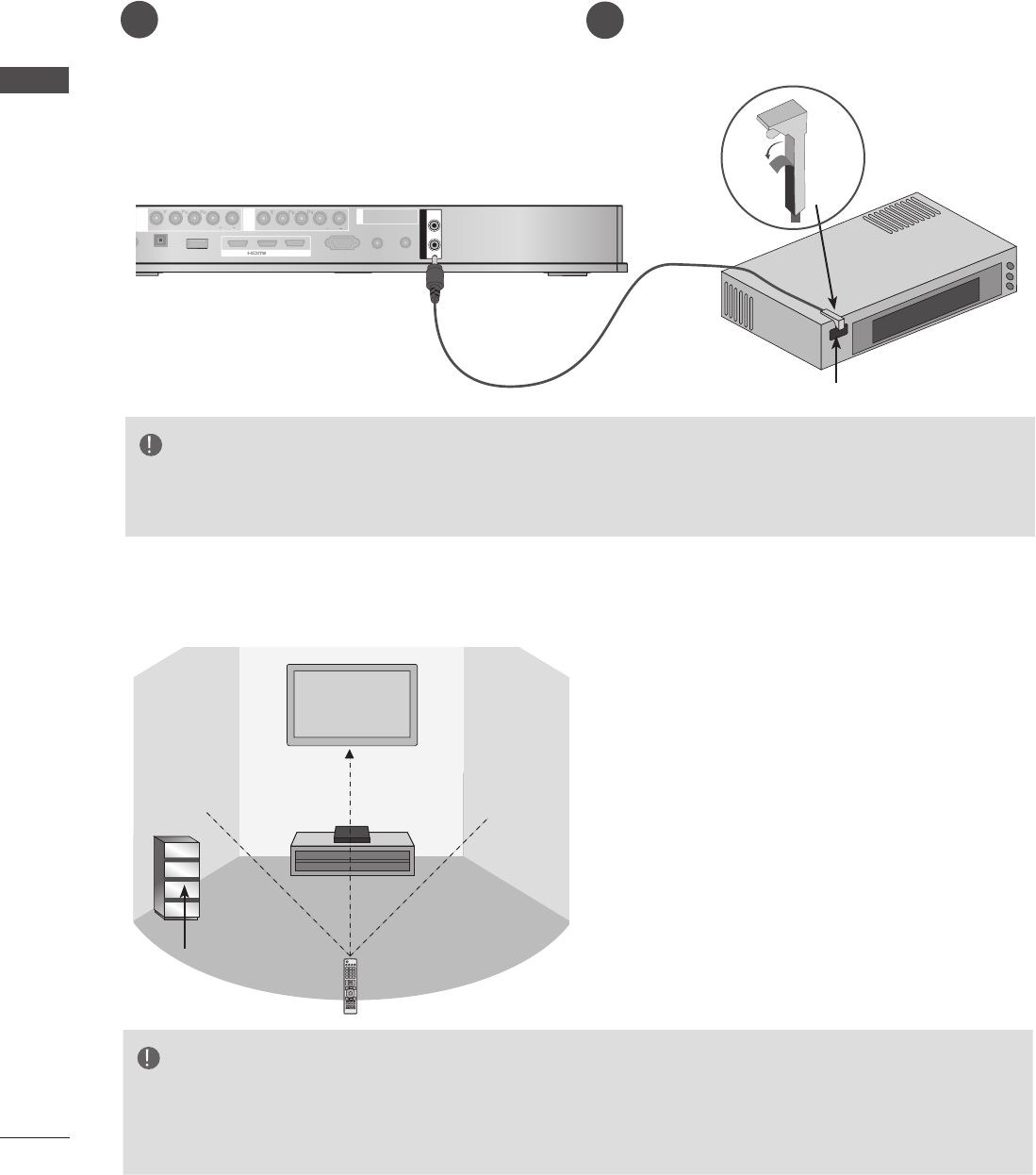
■ The IR blaster allows the LG TV to control external equipment, like a cable box.
Connect the provided IR Blaster cable to the
IR Blaster terminal on the Wireless Media Box.
1After removing the protection paper from the
IR Blaster cable, adhere it to the external
equipment as shown.
2
1
2
DC IN 12V
OPTICAL DIGITAL
AUDIO OUT
SERVICE ONLY
3
RGB IN(PC)
AUDIO IN
RS-232C IN
RGB/DVI
SERVICE ONLY
A
B
COMPONENT / AV IN 1
COMPONENT / AV IN 2
A
R
L(MONO)
AUDIO
VIDEO
B
R
L(MONO)
AUDIO
VIDEO
IR BLASTER
L R L R
/ DVI IN
NOTE
►When you attach the IR Blaster sensor near the remote control sensor of the external device, the
signal can be detected more efficiently.
IR Receiver
1
2
DC IN 12V
OPTICAL DIGITAL
AUDIO OUT
SERVICE ONLY
3
RGB IN(PC)
AUDIO IN
RS-232C IN
RGB/DVI
SERVICE ONLY
A
B
COMPONENT / AV IN 1
COMPONENT / AV IN 2
A
R
L(MONO)
AUDIO
VIDEO
B
R
L(MONO)
AUDIO
VIDEO
IR BLASTER
L R L R
/ DVI IN
Install the external device with the IR Blaster
installed at a location it is not affected by the sig-
nal from the remote controller to the TV.
When the external device with the IR Blaster
installed receives the signal from the remote con-
troller simultaneously with the TV, it may not
operate.
Body of external
device with IR
Blaster installed
NOTE
►For some external devices, the IR Blaster may not operate depending on the performance of the
IR receiver.
►The operation may be delayed due to the sensitivity of the wireless signal.
ATTACHING THE IR BLASTER
OPTIMAL LOCATION OF EXTERNAL DEVICE WITH IR
BLASTER INSTALLED
11
EXTERNAL EQUIPMENT SETUP
CONNECTING WITH A COMPONENT CABLE
■To avoid damaging any equipment, never plug in any power cord until you have finished connecting
all equipment.
■ Image shown may differ slightly from your device.
1
2
DC IN 12V
OPTICAL DIGITAL
AUDIO OUT
SERVICE ONLY
3
RGB IN(PC)
AUDIO IN
RS-232C IN
RGB/DVI
SERVICE ONLY
A
B
COMPONENT / AV IN 1
COMPONENT / AV IN 2
A
R
L(MONO)
AUDIO
VIDEO
B
R
L(MONO)
AUDIO
VIDEO
L R L R
/ DVI IN
A
R
L(MONO)
AUDIO
VIDEO
B
1
2
SERVICE ONLY
3
RGB IN (PC)
AUDIO IN
RS-232C IN
RGB/DVI
SERVICE ONLY
IR BLASTER
A
B
COMPONENT / AV IN 1
COMPONENT / AV IN 2
R
L(MONO)
AUDIO
VIDEO
OPTICAL DIGITAL
AUDIO OUT
DC IN 12V
LRLR
/ DVI IN
IR BLASTER
1
2
DC IN 12V
OPTICAL DIGITAL
AUDIO OUT
SERVICE ONLY
3
RGB IN(PC)
AUDIO IN
RGB/DVI
SERVICE ONLY
/ DVI IN
IR BLASTER
A
R
L(MONO)
AUDIO
VIDEO
B
A
B
COMPONENT / AV IN 1
COMPONENT / AV IN 2
LR
LR
DC IN 12V
OPTICAL DIGITAL
AUDIO OUT
SERVICE ONLY
RGB IN(PC)
AUDIO IN
RGB/DVI
SERVICE ONLY
A
B
COMPONENT / AV IN 1
COMPONENT / AV IN 2
A
R
L(MONO)
AUDIO
VIDEO
B
R
L(MONO)
AUDIO
VIDEO
L R L R
IR BLASTER
1
2
3
/ DVI IN
DC IN 12V
OPTICAL DIGITAL
AUDIO OUT
SERVICE ONLY
RGB IN(PC)
AUDIO IN
RGB/DVI
SERVICE ONLY
A
B
COMPONENT / AV IN 1
COMPONENT / AV IN 2
A
R
L(MONO)
AUDIO
VIDEO
B
R
L(MONO)
AUDIO
VIDEO
L R L R
IR BLASTER
1
2
3
/ DVI IN
1
2
DC IN 12V
OPTICAL DIGITAL
AUDIO OUT
SERVICE ONLY
3
RGB IN(PC)
AUDIO IN
RGB/DVI
SERVICE ONLY
A
B
COMPONENT / AV IN 1
COMPONENT / AV IN 2
A
R
L(MONO)
AUDIO
VIDEO
B
R
L(MONO)
AUDIO
VIDEO
L R L R
/ DVI IN
IR BLASTER
R
L(MONO)
AUDIO
VIDEO
1
2
DC IN 12V
OPTICAL DIGITAL
AUDIO OUT
SERVICE ONLY
3
RGB IN(PC)
AUDIO IN
RGB/DVI
SERVICE ONLY
/ DVI IN
IR BLASTER
A
R
L(MONO)
AUDIO
VIDEO
B
A
B
COMPONENT / AV IN 1
COMPONENT / AV IN 2
R
L(MONO)
AUDIO
VIDEO
LRLR
1
2
DC IN 12V
OPTICAL DIGITAL
AUDIO OUT
SERVICE ONLY
3
AUDIO IN
RGB/DVI
SERVICE ONLY
A
B
COMPONENT / AV IN 1
COMPONENT / AV IN 2
A
R
L(MONO)
AUDIO
VIDEO
B
R
L(MONO)
AUDIO
VIDEO
L R L R
/ DVI IN
IR BLASTER
RGB IN (PC)
1
2
DC IN 12V
OPTICAL DIGITAL
AUDIO OUT
SERVICE ONLY
3
RGB IN(PC)
AUDIO IN
RGB/DVI
SERVICE ONLY
A
B
COMPONENT / AV IN 1
COMPONENT / AV IN 2
A
R
L(MONO)
AUDIO
VIDEO
B
R
L(MONO)
AUDIO
VIDEO
L R L R
/ DVI IN
IR BLASTER
1 2
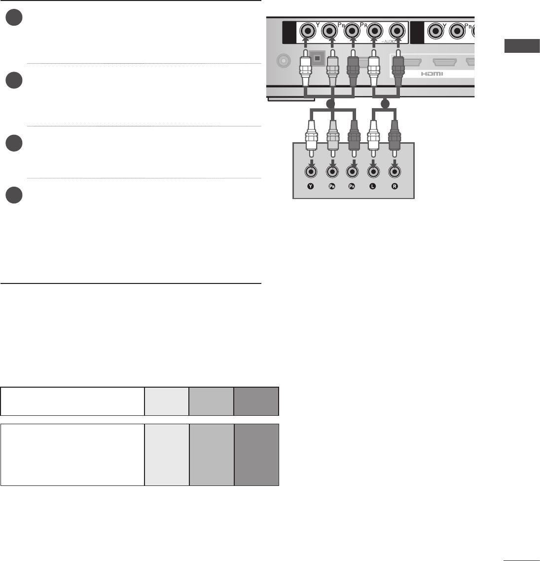
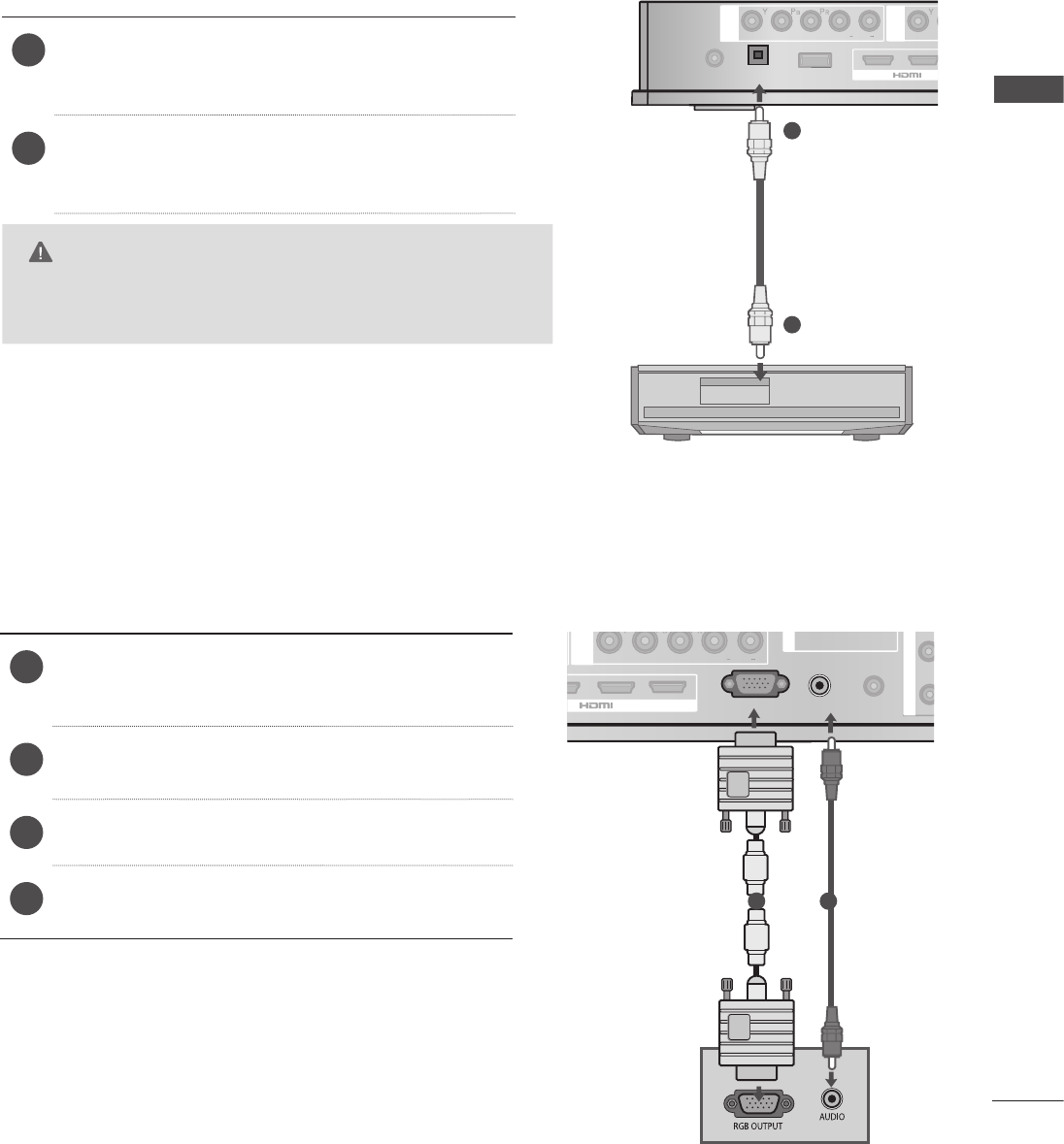
Component Input ports
To achieve better picture quality, connect a DVD player to the component input ports as shown below.
Component ports on the
Wireless Media Box Y PBPR
Video output ports
on DVD player
Y PBPR
Y B-Y R-Y
Y Cb Cr
Y Pb Pr
1Connect the video outputs (Y, PB, PR) of the
external equipment (digital set-top box, DVD,
etc.) to the COMPONENT IN VIDEO jacks
labeled A or B on the Wireless Media Box.
2Connect the audio output of the external equip-
ment (digital set-top box, DVD, etc.) to the
COMPONENT IN AUDIO jacks on the Wireless
Media Box.
3Turn on the external equipment.
(Refer to the external equipment's manual for
operating instructions.)
4Select the Wireless Component1 input source
using the INPUT button on the remote control of
TV.
If connected to COMPONENT IN2, select
Wireless Component2 input source.
Refer to the user manual of the connected TV
for the format of component input.
EXTERNAL EQUIPMENT SETUP
12
EXTERNAL EQUIPMENT SETUP
EXTERNAL EQUIPMENT SETUP
1
2
DC IN 12V
OPTICAL DIGITAL
AUDIO OUT
SERVICE ONLY
3
RGB IN(PC)
AUDIO IN
RS-232C IN
RGB/DVI
SERVICE ONLY
A
B
COMPONENT / AV IN 1
COMPONENT / AV IN 2
A
R
L(MONO)
AUDIO
VIDEO
B
R
L(MONO)
AUDIO
VIDEO
L R L R
/ DVI IN
A
R
L(MONO)
AUDIO
VIDEO
B
1
2
SERVICE ONLY
3
RGB IN (PC)
AUDIO IN
RS-232C IN
RGB/DVI
SERVICE ONLY
IR BLASTER
A
B
COMPONENT / AV IN 1
COMPONENT / AV IN 2
R
L(MONO)
AUDIO
VIDEO
OPTICAL DIGITAL
AUDIO OUT
DC IN 12V
LRLR
/ DVI IN
IR BLASTER
1
2
DC IN 12V
OPTICAL DIGITAL
AUDIO OUT
SERVICE ONLY
3
RGB IN(PC)
AUDIO IN
RGB/DVI
SERVICE ONLY
/ DVI IN
IR BLASTER
A
R
L(MONO)
AUDIO
VIDEO
B
A
B
COMPONENT / AV IN 1
COMPONENT / AV IN 2
LRLR
DC IN 12V
OPTICAL DIGITAL
AUDIO OUT
SERVICE ON
LY
RGB IN(PC)
AUDIO IN
RGB/DVI
SERVICE ONLY
A
B
COMPONENT / AV IN 1
COMPONENT / AV IN 2
A
R
L(MONO)
AUDIO
VIDEO
B
R
L(MONO)
AUDIO
VIDEO
L R L
R
IR BLASTER
1
2
3
/ DVI IN
DC IN 12V
OPTICAL DIGITAL
AUDIO OUT
SERVICE ONLY
RGB IN(PC)
AUDIO IN
RGB/DVI
SERVICE ONLY
A
B
COMPONENT / AV IN 1
COMPONENT / AV IN 2
A
R
L(MONO)
AUDIO
VIDEO
B
R
L(MONO)
AUDIO
VIDEO
L R L R
IR BLASTER
1
2
3
/ DVI IN
1
2
DC IN 12V
OPTICAL DIGITAL
AUDIO OUT
SERVICE ONLY
3
RGB IN(PC)
AUDIO IN
RGB/DVI
SERVICE ONLY
A
B
COMPONENT / AV IN 1
COMPONENT / AV IN 2
A
R
L(MONO)
AUDIO
VIDEO
B
R
L(MONO)
AUDIO
VIDEO
L R L R
/ DVI IN
IR BLASTER
R
L(MONO)
AUDIO
VIDEO
1
2
DC IN 12V
OPTICAL DIGITAL
AUDIO OUT
SERVICE ONLY
3
RGB IN(PC)
AUDIO IN
RGB/DVI
SERVICE ONLY
/ DVI IN
IR BLASTER
A
R
L(MONO)
AUDIO
VIDEO
B
A
B
COMPONENT / AV IN 1
COMPONENT / AV IN 2
R
L(MONO)
AUDIO
VIDEO
LRLR
1
2
DC IN 12V
OPTICAL DIGITAL
AUDIO OUT
SERVICE ONLY
3
AUDIO IN
RGB/DVI
SERVICE ONLY
A
B
COMPONENT / AV IN 1
COMPONENT / AV IN 2
A
R
L(MONO)
AUDIO
VIDEO
B
R
L(MONO)
AUDIO
VIDEO
L R L R
/ DVI IN
IR BLASTER
RGB IN (PC)
1
2
DC IN 12V
OPTICAL DIGITAL
AUDIO OUT
SERVICE ONLY
3
RGB IN(PC)
AUDIO IN
RGB/DVI
SERVICE ONLY
A
B
COMPONENT / AV IN 1
COMPONENT / AV IN 2
A
R
L(MONO)
AUDIO
VIDEO
B
R
L(MONO)
AUDIO
VIDEO
L R L R
/ DVI IN
IR BLASTER
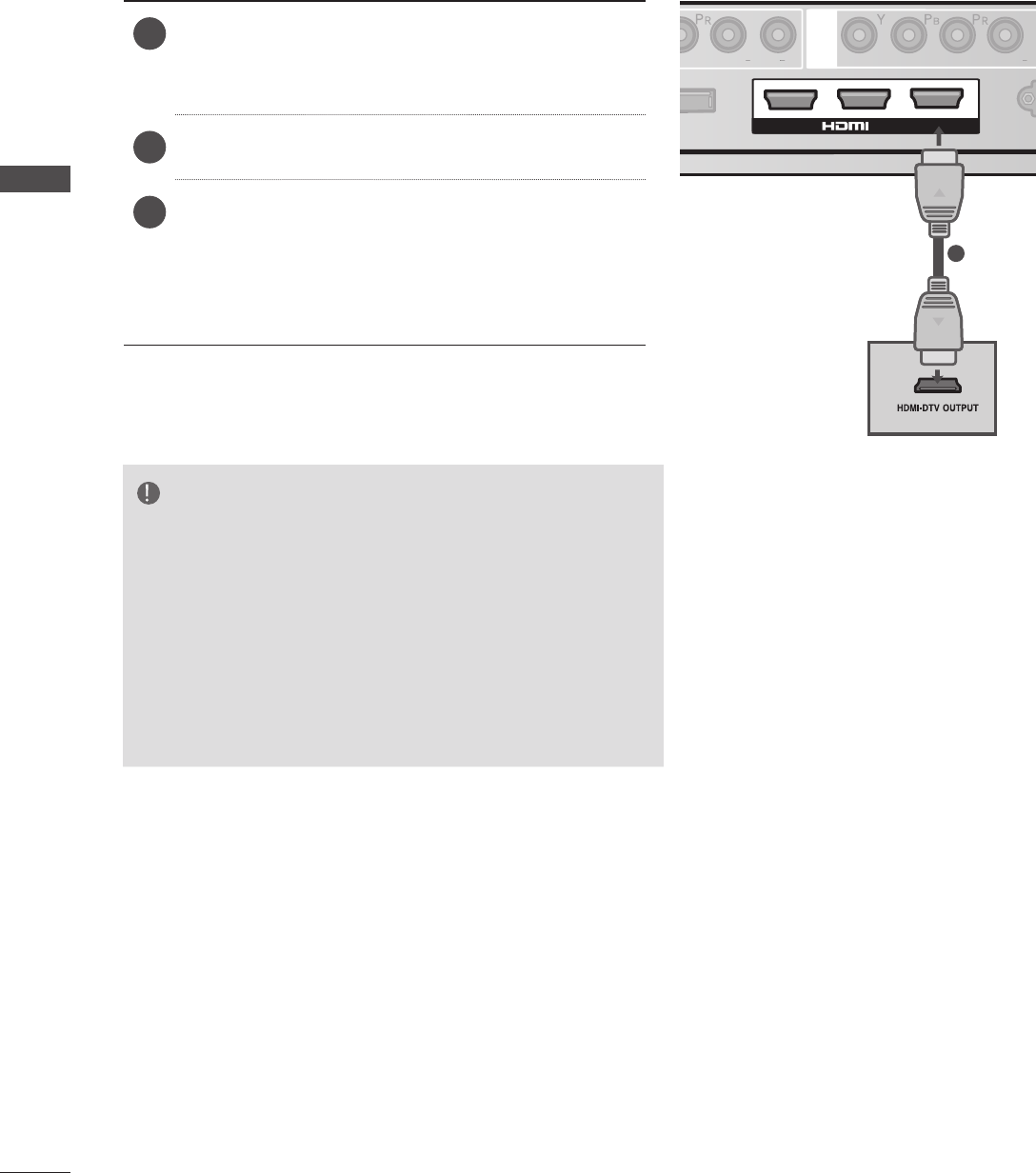
CONNECTING WITH AN HDMI CABLE
1
NOTE
►The Wireless Media Box can receive video and audio
signals simultaneously when using an HDMI cable.
►If the DVD does not support Auto HDMI, you must set
the output resolution appropriately.
►Check that your HDMI cable is version 1.3 or higher. If
the HDMI cables don’t support HDMI version 1.3, flick-
ering or no screen display can result. Please use the
latest cables that support at least HDMI version 1.3.
1Connect the HDMI output of the external equip-
ment (digital set-top box, DVD, etc.) to HDMI/
DVI IN 1, HDMI/DVI IN 2, HDMI/DVI IN 3 or
HDMI IN 4 jack on the Wireless Media Box.
2Turn on the external equipment.
3Select Wireless HDMI1, Wireless HDMI2,
Wireless HDMI3 or Wireless HDMI4 input source
using the INPUT button on the remote control of
TV.
Refer to the user manual of the connected TV for
the format of HDMI input.
13
EXTERNAL EQUIPMENT SETUP
1
2
DC IN 12V
OPTICAL DIGITAL
AUDIO OUT
SERVICE ONLY
3
RGB IN(PC)
AUDIO IN
RS-232C IN
RGB/DVI
SERVICE ONLY
A
B
COMPONENT / AV IN 1
COMPONENT / AV IN 2
A
R
L(MONO)
AUDIO
VIDEO
B
R
L(MONO)
AUDIO
VIDEO
L R L R
/ DVI IN
A
R
L(MONO)
AUDIO
VIDEO
B
1
2
SERVICE ONLY
3
RGB IN (PC)
AUDIO IN
RS-232C IN
RGB/DVI
SERVICE ONLY
IR BLASTER
A
B
COMPONENT / AV IN 1
COMPONENT / AV IN 2
R
L(MONO)
AUDIO
VIDEO
OPTICAL DIGITAL
AUDIO OUT
DC IN 12V
LRLR
/ DVI IN
IR BLASTER
1
2
DC IN 12V
OPTICAL DIGITAL
AUDIO OUT
SERVICE ONLY
3
RGB IN(PC)
AUDIO IN
RGB/DVI
SERVICE ONLY
/ DVI IN
IR BLASTER
A
R
L(MONO)
AUDIO
VIDEO
B
A
B
COMPONENT / AV IN 1
COMPONENT / AV IN 2
LRLR
DC IN 12V
OPTICAL DIGITAL
AUDIO OUT
SERVICE ONLY
RGB IN(PC)
AUDIO IN
RGB/DVI
SERVICE ONLY
A
B
COMPONENT / AV IN 1
COMPONENT / AV IN 2
A
R
L(MONO)
AUDIO
VIDEO
B
R
L(MONO)
AUDIO
VIDEO
L R L R
IR BLASTER
1
2
3
/ DVI IN
DC IN 12V
OPTICAL DIGITAL
AUDIO OUT
SERVICE ONLY
RGB IN(PC)
AUDIO IN
RGB/DVI
SERVICE ONLY
A
B
COMPONENT / AV IN 1
COMPONENT / AV IN 2
A
R
L(MONO)
AUDIO
VIDEO
B
R
L(MONO)
AUDIO
VIDEO
L R L R
IR BLASTER
1
2
3
/ DVI IN
1
2
DC IN 12V
OPTICAL DIGITAL
AUDIO OUT
SERVICE ONLY
3
RGB IN(PC)
AUDIO IN
RGB/DVI
SERVICE ONLY
A
B
COMPONENT / AV IN 1
COMPONENT / AV IN 2
A
R
L(MONO)
AUDIO
VIDEO
B
R
L(MONO)
AUDIO
VIDEO
L R L R
/ DVI IN
IR BLASTER
R
L(MONO)
AUDIO
VIDEO
1
2
DC IN 12V
OPTICAL DIGITAL
AUDIO OUT
SERVICE ONLY
3
RGB IN(PC)
AUDIO IN
RGB/DVI
SERVICE ONLY
/ DVI IN
IR BLASTER
A
R
L(MONO)
AUDIO
VIDEO
B
A
B
COMPONENT / AV IN 1
COMPONENT / AV IN 2
R
L(MONO)
AUDIO
VIDEO
LRLR
1
2
DC IN 12V
OPTICAL DIGITAL
AUDIO OUT
SERVICE ONLY
3
AUDIO IN
RGB/DVI
SERVICE ONLY
A
B
COMPONENT / AV IN 1
COMPONENT / AV IN 2
A
R
L(MONO)
AUDIO
VIDEO
B
R
L(MONO)
AUDIO
VIDEO
L R L R
/ DVI IN
IR BLASTER
RGB IN (PC)
1
2
DC IN 12V
OPTICAL DIGITAL
AUDIO OUT
SERVICE ONLY
3
RGB IN(PC)
AUDIO IN
RGB/DVI
SERVICE ONLY
A
B
COMPONENT / AV IN 1
COMPONENT / AV IN 2
A
R
L(MONO)
AUDIO
VIDEO
B
R
L(MONO)
AUDIO
VIDEO
L R L R
/ DVI IN
IR BLASTER
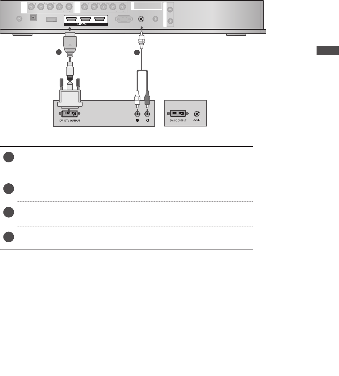
CONNECTING WITH AN HDMI TO DVI CABLE
12
or
1Connect the digital set-top box or the DVI output of the PC to HDMI/DVI IN
1, HDMI/DVI IN 2, HDMI/DVI IN 3 or HDMI IN 4 jack on the Wireless Media
Box.
2Connect the audio output of the digital set-top box or the PC audio output to
the AUDIO IN (RGB/DVI) jack on the Wireless Media Box.
3Turn on the digital set-top box or the PC and the Wireless Media Box.
(Refer to the digital set-top box or the PC manual for operating instructions.)
4Select Wireless HDMI1, Wireless HDMI2, Wireless HDMI3 or Wireless HDMI4
input source using the INPUT button on the remote control of TV.
14
EXTERNAL EQUIPMENT SETUP
EXTERNAL EQUIPMENT SETUP
1
2
DC IN 12V
OPTICAL DIGITAL
AUDIO OUT
SERVICE ONLY
3
RGB IN(PC)
AUDIO IN
RS-232C IN
RGB/DVI
SERVICE ONLY
A
B
COMPONENT / AV IN 1
COMPONENT / AV IN 2
A
R
L(MONO)
AUDIO
VIDEO
B
R
L(MONO)
AUDIO
VIDEO
L R L R
/ DVI IN
A
R
L(MONO)
AUDIO
VIDEO
B
1
2
SERVICE ONLY
3
RGB IN (PC)
AUDIO IN
RS-232C IN
RGB/DVI
SERVICE ONLY
IR BLASTER
A
B
COMPONENT / AV IN 1
COMPONENT / AV IN 2
R
L(MONO)
AUDIO
VIDEO
OPTICAL DIGITAL
AUDIO OUT
DC IN 12V
LRLR
/ DVI IN
IR BLASTER
1
2
DC IN 12V
OPTICAL DIGITAL
AUDIO OUT
SERVICE ONLY
3
RGB IN(PC)
AUDIO IN
RGB/DVI
SERVICE ONLY
/ DVI IN
IR BLASTER
A
R
L(MONO)
AUDIO
VIDEO
B
A
B
COMPONENT / AV IN 1
COMPONENT / AV IN 2
LRLR
DC IN 12V
OPTICAL DIGITAL
AUDIO OUT
SERVICE ONLY
RGB IN(PC)
AUDIO IN
RGB/DVI
SERVICE ONLY
A
B
COMPONENT / AV IN 1
COMPONENT / AV IN 2
A
R
L(MONO)
AUDIO
VIDEO
B
R
L(MONO)
AUDIO
VIDEO
L R L R
IR BLASTER
1
2
3
/ DVI IN
DC IN 12V
OPTICAL DIGITAL
AUDIO OUT
SERVICE ONLY
RGB IN(PC)
AUDIO IN
RGB/DVI
SERVICE ONLY
A
B
COMPONENT / AV IN 1
COMPONENT / AV IN 2
A
R
L(MONO)
AUDIO
VIDEO
B
R
L(MONO)
AUDIO
VIDEO
L R L R
IR BLASTER
1
2
3
/ DVI IN
1
2
DC IN 12V
OPTICAL DIGITAL
AUDIO OUT
SERVICE ONLY
3
RGB IN(PC)
AUDIO IN
RGB/DVI
SERVICE ONLY
A
B
COMPONENT / AV IN 1
COMPONENT / AV IN 2
A
R
L(MONO)
AUDIO
VIDEO
B
R
L(MONO)
AUDIO
VIDEO
L R L R
/ DVI IN
IR BLASTER
R
L(MONO)
AUDIO
VIDEO
1
2
DC IN 12V
OPTICAL DIGITAL
AUDIO OUT
SERVICE ONLY
3
RGB IN(PC)
AUDIO IN
RGB/DVI
SERVICE ONLY
/ DVI IN
IR BLASTER
A
R
L(MONO)
AUDIO
VIDEO
B
A
B
COMPONENT / AV IN 1
COMPONENT / AV IN 2
R
L(MONO)
AUDIO
VIDEO
LRLR
1
2
DC IN 12V
OPTICAL DIGITAL
AUDIO OUT
SERVICE ONLY
3
AUDIO IN
RGB/DVI
SERVICE ONLY
A
B
COMPONENT / AV IN 1
COMPONENT / AV IN 2
A
R
L(MONO)
AUDIO
VIDEO
B
R
L(MONO)
AUDIO
VIDEO
L R L R
/ DVI IN
IR BLASTER
RGB IN (PC)
1
2
DC IN 12V
OPTICAL DIGITAL
AUDIO OUT
SERVICE ONLY
3
RGB IN(PC)
AUDIO IN
RGB/DVI
SERVICE ONLY
A
B
COMPONENT / AV IN 1
COMPONENT / AV IN 2
A
R
L(MONO)
AUDIO
VIDEO
B
R
L(MONO)
AUDIO
VIDEO
L R L R
/ DVI IN
IR BLASTER
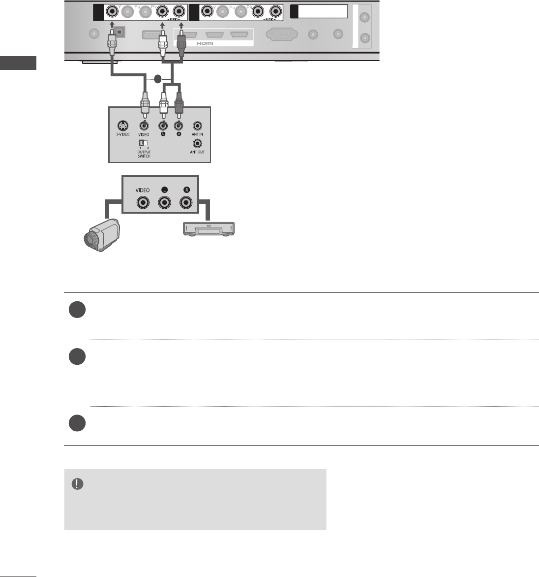
CONNECTING WITH RCA CABLE
1
Camcorder
Video Game Set
or
NOTE
►If you have a mono VCR, connect the audio cable from
the VCR to the AUDIO L/MONO jack of the
media box
.
1Connect the AUDIO/VIDEO jacks between Wireless Media Box and VCR or external equip-
ment.
2Insert a video tape into the VCR and press PLAY on the VCR. (Refer to the VCR owner’s
manual.)
Or, Operate the corresponding external equipment.
(Refer to external equipment operating guide.)
3Select Wireless AV2 input source using the INPUT button on the remote control of TV.
If connected to AV1 input, select Wireless AV2 input source.
15
EXTERNAL EQUIPMENT SETUP
1
2
DC IN 12V
OPTICAL DIGITAL
AUDIO OUT
SERVICE ONLY
3
RGB IN(PC)
AUDIO IN
RS-232C IN
RGB/DVI
SERVICE ONLY
A
B
COMPONENT / AV IN 1
COMPONENT / AV IN 2
A
R
L(MONO)
AUDIO
VIDEO
B
R
L(MONO)
AUDIO
VIDEO
L R L R
/ DVI IN
A
R
L(MONO)
AUDIO
VIDEO
B
1
2
SERVICE ONLY
3
RGB IN (PC)
AUDIO IN
RS-232C IN
RGB/DVI
SERVICE ONLY
IR BLASTER
A
B
COMPONENT / AV IN 1
COMPONENT / AV IN 2
R
L(MONO)
AUDIO
VIDEO
OPTICAL DIGITAL
AUDIO OUT
DC IN 12V
LRLR
/ DVI IN
IR BLASTER
1
2
DC IN 12V
OPTICAL DIGITAL
AUDIO OUT
SERVICE ONLY
3
RGB IN(PC)
AUDIO IN
RGB/DVI
SERVICE ONLY
/ DVI IN
IR BLASTER
A
R
L(MONO)
AUDIO
VIDEO
B
A
B
COMPONENT / AV IN 1
COMPONENT / AV IN 2
LRLR
DC IN 12V
OPTICAL DIGITAL
AUDIO OUT
SERVICE ONLY
RGB IN(PC)
AUDIO IN
RGB/DVI
SERVICE ONLY
A
B
COMPONENT / AV IN 1
COMPONENT / AV IN 2
A
R
L(MONO)
AUDIO
VIDEO
B
R
L(MONO)
AUDIO
VIDEO
L R L R
IR BLASTER
1
2
3
/ DVI IN
DC IN 12V
OPTICAL DIGITAL
AUDIO OUT
SERVICE ONLY
RGB IN(PC)
AUDIO IN
RGB/DVI
SERVICE ONLY
A
B
COMPONENT / AV IN 1
COMPONENT / AV IN 2
A
R
L(MONO)
AUDIO
VIDEO
B
R
L(MONO)
AUDIO
VIDEO
L R L R
IR BLASTER
1
2
3
/ DVI IN
1
2
DC IN 12V
OPTICAL DIGITAL
AUDIO OUT
SERVICE ONLY
3
RGB IN(PC)
AUDIO IN
RGB/DVI
SERVICE ONLY
A
B
COMPONENT / AV IN 1
COMPONENT / AV IN 2
A
R
L(MONO)
AUDIO
VIDEO
B
R
L(MONO)
AUDIO
VIDEO
L R L R
/ DVI IN
IR BLASTER
R
L(MONO)
AUDIO
VIDEO
1
2
DC IN 12V
OPTICAL DIGITAL
AUDIO OUT
SERVICE ONLY
3
RGB IN(PC)
AUDIO IN
RGB/DVI
SERVICE ONLY
/ DVI IN
IR BLASTER
A
R
L(MONO)
AUDIO
VIDEO
B
A
B
COMPONENT / AV IN 1
COMPONENT / AV IN 2
R
L(MONO)
AUDIO
VIDEO
LRLR
1
2
DC IN 12V
OPTICAL DIGITAL
AUDIO OUT
SERVICE ONLY
3
AUDIO IN
RGB/DVI
SERVICE ONLY
A
B
COMPONENT / AV IN 1
COMPONENT / AV IN 2
A
R
L(MONO)
AUDIO
VIDEO
B
R
L(MONO)
AUDIO
VIDEO
L R L R
/ DVI IN
IR BLASTER
RGB IN (PC)
1
2
DC IN 12V
OPTICAL DIGITAL
AUDIO OUT
SERVICE ONLY
3
RGB IN(PC)
AUDIO IN
RGB/DVI
SERVICE ONLY
A
B
COMPONENT / AV IN 1
COMPONENT / AV IN 2
A
R
L(MONO)
AUDIO
VIDEO
B
R
L(MONO)
AUDIO
VIDEO
L R
L R
/ DVI IN
IR BLASTER
1
2
DIGITAL AUDIO OUT SETUP
You can output the
Wireless Media Box
’s audio signal to external audio equipment via the Optical
Digital Audio Output port. This port uses a standard optical cable.
CAUTION
► Do not look into the optical output port. Looking at the laser
beam may damage your vision.
1Connect one end of an optical cable to the
OPTICAL DIGITAL AUDIO OUT port on the
Wireless Media Box.
2 Connect the other end of the optical cable to
the digital audio (Optical) input on the audio
equipment.
CONNECTING WITH RGB
You can also connect devices using the RGB input. This connection uses a standard VGA cable
(D-Sub 15 pin cable). This
Wireless Media Box
supports Plug and Play capability, meaning that the PC
adjusts automatically to the
Wireless Media Box
's settings.
1
2
DC IN 12V
OPTICAL DIGITAL
AUDIO OUT
SERVICE ONLY
3
RGB IN(PC)
AUDIO IN
RS-232C IN
RGB/DVI
SERVICE ONLY
A
B
COMPONENT / AV IN 1
COMPONENT / AV IN 2
A
R
L(MONO)
AUDIO
VIDEO
B
R
L(MONO)
AUDIO
VIDEO
L R L R
/ DVI IN
A
R
L(MONO)
AUDIO
VIDEO
B
1
2
SERVICE ONLY
3
RGB IN (PC)
AUDIO IN
RS-232C IN
RGB/DVI
SERVICE ONLY
IR BLASTER
A
B
COMPONENT / AV IN 1
COMPONENT / AV IN 2
R
L(MONO)
AUDIO
VIDEO
OPTICAL DIGITAL
AUDIO OUT
DC IN 12V
LRLR
/ DVI IN
IR BLASTER
1
2
DC IN 12V
OPTICAL DIGITAL
AUDIO OUT
SERVICE ONLY
3
RGB IN(PC)
AUDIO IN
RGB/DVI
SERVICE ONLY
/ DVI IN
IR BLASTER
A
R
L(MONO)
AUDIO
VIDEO
B
A
B
COMPONENT / AV IN 1
COMPONENT / AV IN 2
LRLR
DC IN 12V
OPTICAL DIGITAL
AUDIO OUT
SERVICE ONLY
RGB IN(PC)
AUDIO IN
RGB/DVI
SERVICE ONLY
A
B
COMPONENT / AV IN 1
COMPONENT / AV IN 2
A
R
L(MONO)
AUDIO
VIDEO
B
R
L(MONO)
AUDIO
VIDEO
L R L R
IR BLASTER
1
2
3
/ DVI IN
DC IN 12V
OPTICAL DIGITAL
AUDIO OUT
SERVICE ONLY
RGB IN(PC)
AUDIO IN
RGB/DVI
SERVICE ONLY
A
B
COMPONENT / AV IN 1
COMPONENT / AV IN 2
A
R
L(MONO)
AUDIO
VIDEO
B
R
L(MONO)
AUDIO
VIDEO
L R L R
IR BLASTER
1
2
3
/ DVI IN
1
2
DC IN 12V
OPTICAL DIGITAL
AUDIO OUT
SERVICE ONLY
3
RGB IN(PC)
AUDIO IN
RGB/DVI
SERVICE ONLY
A
B
COMPONENT / AV IN 1
COMPONENT / AV IN 2
A
R
L(MONO)
AUDIO
VIDEO
B
R
L(MONO)
AUDIO
VIDEO
L R L R
/ DVI IN
IR BLASTER
R
L(MONO)
AUDIO
VIDEO
1
2
DC IN 12V
OPTICAL DIGITAL
AUDIO OUT
SERVICE ONLY
3
RGB IN(PC)
AUDIO IN
RGB/DVI
SERVICE ONLY
/ DVI IN
IR BLASTER
A
R
L(MONO)
AUDIO
VIDEO
B
A
B
COMPONENT / AV IN 1
COMPONENT / AV IN 2
R
L(MONO)
AUDIO
VIDEO
LRLR
1
2
DC IN 12V
OPTICAL DIGITAL
AUDIO OUT
SERVICE ONLY
3
AUDIO IN
RGB/DVI
SERVICE ONLY
A
B
COMPONENT / AV IN 1
COMPONENT / AV IN 2
A
R
L(MONO)
AUDIO
VIDEO
B
R
L(MONO)
AUDIO
VIDEO
L R L R
/ DVI IN
IR BLASTER
RGB IN (PC)
1
2
DC IN 12V
OPTICAL DIGITAL
AUDIO OUT
SERVICE ONLY
3
RGB IN(PC)
AUDIO IN
RGB/DVI
SERVICE ONLY
A
B
COMPONENT / AV IN 1
COMPONENT / AV IN 2
A
R
L(MONO)
AUDIO
VIDEO
B
R
L(MONO)
AUDIO
VIDEO
L R L R
/ DVI IN
IR BLASTER
1 2
1Connect the RGB output of the PC to the RGB
IN (PC) jack on the Wireless Media Box.
2Connect the PC audio output to the AUDIO IN
(RGB/DVI) jack on the Wireless Media Box.
3Turn on the PC and the Wireless Media Box.
4Select Wireless RGB input source using the
INPUT button on the remote control of TV.
16
EXTERNAL EQUIPMENT SETUP
EXTERNAL EQUIPMENT SETUP
NOTE
►There may be interference relating to resolution,
vertical pattern, contrast or brightness in PC
mode. Change the PC mode to another resolution
or change the refresh rate to another rate or
adjust the brightness and contrast on the menu
until the picture is clear. If the refresh rate of the
PC graphic card can not be changed, change the
PC graphic card or consult the manufacturer of
the PC graphic card.
►The synchronization input waveform for Horizontal
and Vertical frequencies are separate.
►Connect the signal cable from the monitor output
port of the PC to the RGB (PC) port of the
Wireless Media Box or the signal cable from the
HDMI output port of the PC to the HDMI IN (or
HDMI/DVI IN) port on the Wireless Media Box.
►Connect the audio cable from the PC to the Audio
input on the Wireless Media Box. (Audio cables are
not included with the Wireless Media Box).
►DOS mode may not work depending on the video
card if you use an HDMI to DVI cable.
►If you use too long an RGB-PC cable, there may be
interference on the screen. We recommend using
under 5m of cable. This provides the best picture
quality.
►When an unsupported resolution or graphic card is
used on the PC, it may cause some errors.
RGB-PC, HDMI/DVI-PC mode
SUPPORTED DISPLAY RESOLUTION
Resolution Horizontal
Frequency(kHz) Vertical
Frequency(Hz)
720x400 31.468 70.08
640x480 31.469 59.94
800x600 37.879 60.31
1024x768 48.363 60.00
1280x768 47.78 59.87
1360x768 47.72 59.80
1280x1024 63.595 60.00
1920x1080
(RGB-PC) 66.587 59.93
1920x1080
(HDMI-PC) 67.5 60.00
17
WATCHING TV / PROGRAMME CONTROL
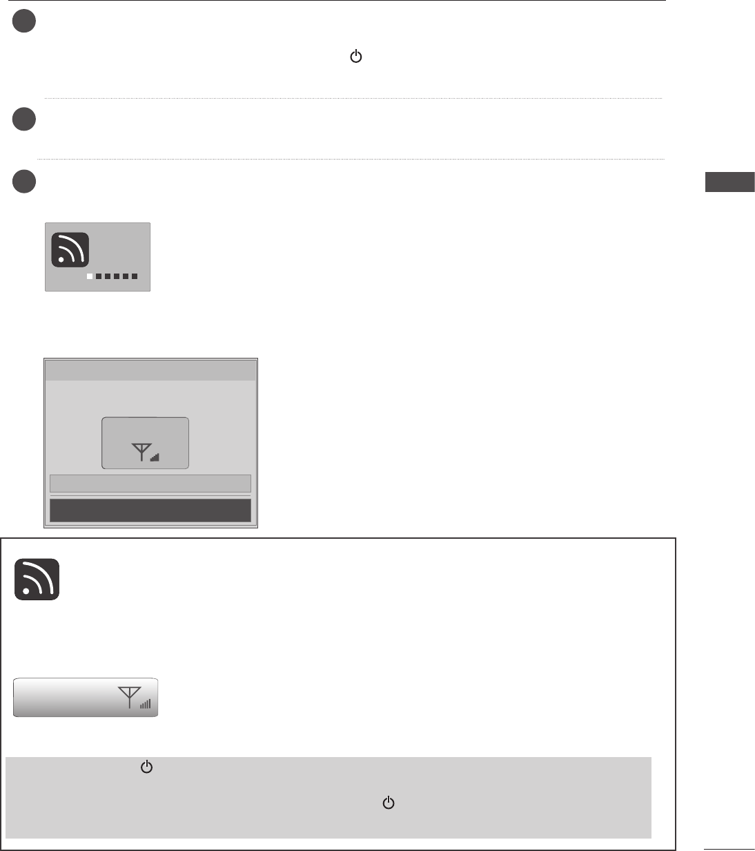
When the power of the TV is turned on, the picture will be displayed as follows by stage accord-
ing to the wireless connecting procedure.
3
Firstly, connect the power cord correctly on the Wireless Media Box.
At this stage, the Wireless Media Box switches to standby mode.
When installing for the first time, the press the (Power) button of the Wireless Media Box to
turn on the power.)
Use the remote controller of the TV to turn on the power. The power of the Wireless Media
Box will automatically be turned on. Point the remote controller toward the TV.
2
1
Connecting
wireless TV.
■ If you turn on the power of the TV when the external input of the Wireless
Media Box is selected, it will be displayed when the external input of the
Wireless Media Box is trying to connect to the wireless network.
■ This is the screen displayed when trying to connect wireless after connect-
ing the Wireless Ready Dongle while the TV is turned off.
■ The screen becomes dark briefly right before the connection process is
complete.
Wireless Connection
Wireless Connection Established. Now you
can use wireless to an external input.
Wireless Signal
See the connection device
Close
■ When the connection is successful, the above dis-
play will disappear and the screen on the left will be
displayed.
■ This is the screen shown once the wireless connec-
tion is connected.
■ When the connection fails, check the power of the
Wireless Media Box.
■ Left icon is to distinguish the external input of TV and the wireless external input of
Wireless Media Box.
■ After the Wireless Ready Dongle is successfully installed, wireless external input will be
shown additionally in the TV menu related to external input. (Input List, Input Label,
Timer, Input Block and Picture Wizard)
■ Operate the external input of Wireless Media Box using the remote controller of the TV.
Wireless Signal
■ When you press the OK button while viewing the external input of
Wireless Media Box, the information of the current input and the
strength of the wireless signal will be displayed on the bottom left side.
(When you press the BACK/EXIT key, the information will disappear.)
■ If you press the (Power) button of the Wireless Media Box manually to turn it off when both
the TV and Wireless Media Box are turned on, you will not be able to turn on the power using
the remote controller of the TV. At this time, press the (Power) button of the Wireless Media
Box to turn on the power.
WATCHING TV / PROGRAM CONTROL
TURNING ON THE WIRELESS MEDIA BOX
18
WATCHING TV / PROGRAMME CONTROL
WATCHING TV / PROGRAM CONTROL
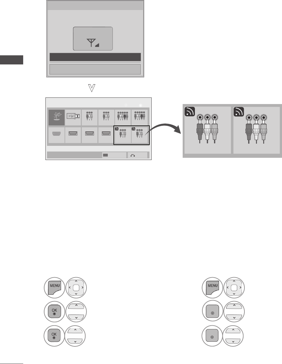
Only input signals which are connected to a TV or Wireless Media Box can be activated and selected.
Wireless Connection
Wireless Connection Established. Now you
can use wireless to an external input.
Wireless Signal
See the connection device
Close
When you select the "See the connection device",
you can see the connected device.
■ Select your desired Source.
When you change the input source, it can take up to 10 seconds depending on the wireless environment.
Antenna USB
HDMI4
AV1 AV2 Component1
RGB
OK
Move
Input List
Component2
HDMI2 HDMI3 AV1 AV2
Input Label Exit
Wireless input source
* This is the screen when the Wireless Ready Dongle is connected to HDMI/DVI IN 1. HDMI terminal connected
to Wireless Ready Dongle is not displayed on the list of external inputs.
AV1 AV2
You can control the external device (VCR, DVD player etc.) connected to the Media box from the TV
using the infrared controller called IR-Blaster.
Set up the TV menu as shown below.
1Select OPTION.
2Select IR Blaster.
3Select On.
• Press the MENU/EXIT button to return to normal TV viewing.
• Press the BACK button to move to the previous menu screen.
1Select OPTION.
2
ENTER
Select IR Blaster.
3
ENTER
Select On.
or
INPUT LIST
IR BLASTER SETUP
19
APPENDIX
DVD
BRAND CODE
PHILIPS RC6
SAMSUNG LC7461
TOSHIBA NEC
PANASONIC AV162
LG TC9012
DENON LRC3715
PIONEER NEC
HITACHI NEC
GPX SAA3004
DVR-VCR
BRAND CODE
TIVO S2 uPD6121
SAMSUNG TC9012
TOSHIBA NEC
PANASONIC AV162
PHILIPS SAA3010
HITACHI NEC
LG NEC
MITSUBISHI JVC
HITACHI M50110
GO VIDEO SAA3004
AUDIO
BRAND CODE
DENON LRC3715
YAMAHA NEC
MARANTZ SAA3010
INTEGRA,
ONKYO NEC
H/K NEC
PIONEER NEC
BOSE NEC
LEXICON uPD6121
ROTEL uPD6121
SHERWOOD uPD6121
XM SAA3010
REALISTIC TC9148
PARASOUND TC9132P
INSIGNIA SAA3004
CBL-SAT
BRAND CODE
S/A,PIONEER D6108
MOTOROLA MOTOROLA
DIRECTV DIRECTV
MOXI MOXI
VOOM BU5962
SAMSUNG uPD6121
LG NEC
PIONEER M50110
APPENDIX
IR CODE LIST
20
APPENDIX
APPENDIX
Items U-NII-I U-NII-II U-NII-II extended U-NII-III
Frequency range [GHz] 5.15~5.25 5.25~5.35 5.47~5.725 5.725~5.825
Transmission OFDM OFDM OFDM OFDM
RF Output Power (Max.) [dBm] 15 15 15 15
Antenna Gain (Max.) [dBi] 3.5 3.5 3.5 3.5
Channel Table [MHz]
(Center frequency) Depends on the country region (Please see the Frequency Table)
Channel units 2 ~ 11
Depends on the country region (Please see the Frequency Table)
■ Band channel used by the country could be different.
Wireless Media Box
Wireless Ready Dongle
Items U-NII-I U-NII-II U-NII-II extended U-NII-III
Frequency range [GHz] 5.15~5.25 5.25~5.35 5.47~5.725 5.725~5.825
Transmission OFDM OFDM OFDM OFDM
RF Output Power (Max.) [dBm] 16 16 16 16
Antenna Gain (Max.) [dBi] 3.5 3.5 3.5 3.5
Channel Table [MHz]
(Center frequency) Depends on the country region (Please see the Frequency Table)
Channel units 2 ~ 11
Depends on the country region (Please see the Frequency Table)
RF SPECIFICATIONS
21
APPENDIX
20MHz
ͦͩ͢͡ ͦͣ͡͡ ͦͣͣ͡ ͦͣͥ͡ ͦͣͧ͡ ͦͣͩ͡ ͦͤ͡͡ ͦͤͣ͡ ͦͦ͡͡ ͦͦͣ͡ ͦͦͥ͡ ͦͦͧ͡ ͦͦͩ͡ ͦͧ͡͡ ͦͧͣ͡ ͦͧͥ͡ ͦͧͧ͡ ͦͧͩ͡ ͦͨͥͦ ͦͨͧͦ ͦͨͩͦ ͦͩͦ͡
40MHz
20MHz
ͦͩ͢͡ ͦͣ͡͡ ͦͣͣ͡ ͦͣͥ͡ ͦͣͧ͡ ͦͣͩ͡ ͦͤ͡͡ ͦͤͣ͡ ͦͦ͡͡ ͦͦͣ͡ ͦͦͥ͡ ͦͦͧ͡ ͦͦͩ͡ ͦͧ͡͡ ͦͧͣ͡ ͦͧͥ͡ ͦͧͧ͡ ͦͧͩ͡ ͦͨͥͦ ͦͨͧͦ ͦͨͩͦ ͦͩͦ͡
40MHz
͑
B W\C H #36 #40 #44 #48 #52 #56 #60 #64 #100 #104 #108 #112 #116 #120 #124 #128 #132 #136 #140 #149 #153 #157 #161 #165
20MHz
ͦͩ͢͡ ͦͣ͡͡ ͦͣͣ͡ ͦͣͥ͡ ͦͣͧ͡ ͦͣͩ͡ ͦͤ͡͡ ͦͤͣ͡ ͦͦ͡͡ ͦͦͣ͡ ͦͦͥ͡ ͦͦͧ͡ ͦͨͥͦ ͦͨͧͦ ͦͨͩͦ ͦͩͦ͡
40MHz
20MHz
ͦͩ͢͡ ͦͣ͡͡ ͦͣͣ͡ ͦͣͥ͡ ͦͣͧ͡ ͦͣͩ͡ ͦͤ͡͡ ͦͤͣ͡ ͦͦ͡͡ ͦͦͣ͡ ͦͦͥ͡ ͦͦͧ͡ ͦͦͩ͡ ͦͧ͡͡ ͦͧͣ͡ ͦͧͥ͡ ͦͧͧ͡ ͦͧͩ͡
40MHz
20MHz
ͦͩ͢͡ ͦͣ͡͡ ͦͣͣ͡ ͦͣͥ͡ ͦͣͧ͡ ͦͣͩ͡ ͦͤ͡͡ ͦͤͣ͡ ͦͨͥͦ ͦͨͧͦ ͦͨͩͦ ͦͩͦ͡
40MHz
20MHz
ͦͩ͢͡ ͦͣ͡͡ ͦͣͣ͡ ͦͣͥ͡ ͦͣͧ͡ ͦͣͩ͡ ͦͤ͡͡ ͦͤͣ͡
40MHz
20MHz
͑͑͑͑͑͑ ͦͤ͡͡ ͦͤͣ͡ ͦͦ͡͡ ͦͦͣ͡ ͦͦͥ͡ ͦͦͧ͡ ͦͦͩ͡ ͦͧ͡͡ ͦͧͣ͡ ͦͧͥ͡ ͦͧͧ͡ ͦͧͩ͡ ͑ ͦͨͥͦ ͦͨͧͦ ͦͨͩͦ ͦͩͦ͡
40MHz
20MHz
ͦͩ͢͡ ͦͣ͡͡ ͦͣͣ͡ ͦͣͥ͡ ͦͦ͡͡ ͦͦͣ͡ ͦͦͥ͡ ͦͦͧ͡ ͑ ͑ ͑ ͑ ͑ ͑ ͑ ͦͨͥͦ ͦͨͧͦ ͦͨͩͦ ͦͩͦ͡
40MHz
20MHz
ͦͩ͢͡ ͦͣ͡͡ ͦͣͣ͡ ͦͣͥ͡ ͦͣͧ͡ ͦͣͩ͡ ͦͤ͡͡ ͦͤͣ͡ ͑ ͑ ͑ ͑ ͑ ͑ ͑ ͑ ͑ ͑ ͑
40MHz
20MHz
͑ ͑ ͑ ͑ ͑ ͑ ͑ ͑ ͑ ͑ ͑ ͑ ͑ ͑ ͑ ͦͨͥͦ ͦͨͧͦ ͦͨͩͦ ͦͩͦ͡
40MHz
5.15GHz ~ 5.25GHz 5.25GHz ~ 5.35GHz 5.47~5.725 GHz 5.725~5.850GHz
ͦͨͦͦ ͦͨͪͦͦͪ͢͡ ͦͣͤ͡ ͦͣͨ͡ ͦͤ͢͡ ͦͦ͢͡ ͦͦͦ͡
5.15GHz ~ 5.25GHz
5.25GHz ~ 5.35GHz
5.47~5.725 GHz
ͦͪ͢͡ ͦͣͤ͡ ͦͣͨ͡ ͦͤ͢͡ ͦͨͦͦ ͦͨͪͦ
5.725~5.850GHz
5.15GHz ~ 5.25GHz 5.25GHz ~ 5.35GHz 5.47~5.65 GHz
͑ ͑ ͑ ͑ ͑ ͑ ͑ ͑ ͦͨͦͦ ͦͨͪͦ
5.15GHz ~ 5.25GHz 5.25GHz ~ 5.35GHz 5.47~5.65 GHz 5.725~5.850GHz
ͦͨͦͦ ͦͨͪͦ
5.725~5.850GHz
͑ ͦͤ͢͡ ͦͦ͢͡ ͦͦͦ͡ ͦͦͪ͡ ͦͧͤ͡ ͦͧͨ͡
5.15GHz ~ 5.25GHz
5.25GHz ~ 5.35GHz
5.47~5.725 GHz
ͦͧͨͦͦ͢͡͡ ͦͦͦ͡ ͦͦͪ͡ ͦͧͤͦͪ͢͡͡ ͦͣͤ͡ ͦͣͨ͡ ͦͤ͢͡ ͦͨͦͦ ͦͨͪͦ
5.725~5.850GHz
5.15GHz ~ 5.25GHz
5.25GHz ~ 5.35GHz
5.47~5.725 GHz
5.725~5.850GHz
ͦͪ͢͡ ͦͣͤ͡ ͦͣͨ͡ ͦͤ͢͡
5.15GHz ~ 5.25GHz 5.25GHz ~ 5.35GHz 5.47~5.725 GHz
ͦͧͨͦͪ͢͡͡ ͦͣͤ͡ ͦͣͨ͡ ͦͤ͢͡
5.725~5.850GHz
ͦͦ͢͡ ͦͦͦ͡ ͦͦͪ͡ ͦͧͤ͡ ͦͨͦͦ ͦͨͪͦ
5.725~5.850GHz
5.15GHz ~ 5.25GHz
5.25GHz ~ 5.35GHz
5.47~5.725 GHz
ͦͪ͢͡ ͦͣͤ͡ ͦͣͨ͡ ͦͤ͢͡ ͦͦ͢͡ ͦͦͦ͡ ͦͦͪ͡ ͦͧͤ͡ ͦͧͨ͡
5.15GHz ~ 5.25GHz 5.25GHz ~ 5.35GHz 5.47~5.725 GHz
͑͑ ͑ ͑ ͑ͦͪ͢͡ ͦͣͤ͡
5.725~5.850GHz
ͦͣͨ͡ ͦͤ͢͡
5.15GHz ~ 5.25GHz 5.25GHz ~ 5.35GHz 5.47~5.57 GHz
ͦͪ͢͡ ͦͣͤ͡ ͦͦ͢͡ ͦͦͦ͡ ͑ ͑ ͑ ͦͨͦͦ
͑ ͑
ͦͨͪͦ
5.725~5.850GHz
Hongkong / Thailand
Oman / Jordan / Peru / Qatar
South Africa / Uganda / Honduras
UAE / Nicaragua / Argentina /
Brazil
Australia / New Zealand
US / CANADA
Turkey / Saudi Arabia
Algeria /Philippines
Mexico / Malaysia
Chile / Egypt / Bahrain
India / Singapore / Venezuela
Vietnam / Israel
/ Kuwait
Taiwan
Kenya
Yemen
China / Pakistan / Iran
FREQUENCY TABLE
22
APPENDIX
APPENDIX
MODELS Wireless Media Box
(AN-WL100W)
Dimensions
(Width x Height x Depth) 326.0 mm x 42.8 mm x 226.0 mm
(12.8 inch x 1.7 inch x 8.9 inch)
Weight 1.5 kg (3.3 lb)
Power requirement
DC 12 V 1.1 A
Adapter
In : AC 100-240 V~ 50 / 60 Hz
Out : DC 12 V 2.5A
(Adaptor model No. : PA-1031-1 ( LITE-ON) , EADP-30PB B (DELTA) )
MODELS Wireless Ready Dongle
Dimensions
(Width x Height x Depth) 148.0 mm x 23.0 mm x 78.0 mm
(5.8 inch x 0.9 inch x 3.1 inch)
Weight 0.2 kg (0.4 lb)
Power Consumption
9 W
Environment condition
Operating
Temperature
Operating Humidity
0 °C ~ 40 °C (32 °F ~ 104 °F)
Less than 80 %
Storage Temperature
Storage Humidity
-20 °C ~ 60 °C (-4 °F ~ 140 °F)
Less than 85 %
■ The specifications shown above may be changed without prior notice for quality improvement.
The video function does not work.
No picture & No sound
■Check whether the TV and the Wireless Media Box are turned on.
■Is the power cord inserted correctly into the adapter?
■Is the adapter plug inserted correctly into the Wireless Media Box?
No or poor colour
or poor picture
■Adjust Colour in menu option.
■Are the video cables installed properly?
■Activate any function to restore the brightness of the picture.
Horizontal/vertical bars
or picture shaking ■Check for local interference such as an electrical appliance or power tool.
No picture
when connecting
HDMI
■Check that your HDMI cable is version 1.3 or higher.
If the HDMI cables don’t support HDMI version 1.3, flickering or no screen display
can result. Please use the latest cables that support at least HDMI version 1.3.
PRODUCT SPECIFICATIONS
TROUBLESHOOTING
23
APPENDIX
The audio function does not work.
Picture OK & No
sound
■Press the + or - button.
■Sound muted? Press MUTE button.
■Are the audio cables installed properly?
No output from one
of the speakers ■Adjust Balance in menu option.
No sound when con-
necting HDMI
■Check HDMI cable over version 1.3.
There is a problem in PC mode. (Only PC mode applied)
The signal is out of
range
(Invalid format)
■Adjust resolution, horizontal frequency, or vertical frequency.
■Check the input source.
Vertical bar or stripe on
background &
Horizontal Noise &
Incorrect position
■Use Auto configure or adjust clock, phase, or H/V position. (Option)
Screen colour is
unstable or single
colour
■Check the signal cable.
■Reinstall the PC video card.
This is when there is an issue with the wireless connection.
Connecting Wireless TV
screen is not displayed.
■Check the connection of the 20 pin cable (Power/Control) between the
Wireless Ready TV and Wireless Ready Dongle. (Refer to the p. 6)
■Set up the external input of TV to wireless input.
"무선 연결 중"
"Connecting wireless"
screen is displayed but
the wireless input is not
activated.
■Check the connection of the HDMI cable between the Wireless Ready TV
and Wireless Ready Dongle. (Refer to the p. 6)
■Check whether the power of the Wireless Media Box is turned on. (Refer to
the p. 17)
■ Check whether an external device is connected to Wireless Media Box. Only
the wireless input with the external device connected will be activated.
It reconnects after wire-
less connection is estab-
lished
■This happens when there is wireless interference from surrounding devices
or when the wireless signal is weak. Check the installation range of the
Wireless Media Box. (Refer to the p. 9)
Screen is distorted after
the wireless connection.
■ This can happen when the wireless signal is weak. Check the installation
range of the Wireless Media Box. (Refer to the p. 9)
After wireless connection
is established, horizontal
line patterns are instantly
shown on the screen.
■This can happen when there are wireless devices using 5 GHz bandwidth.
Keep products that interfere with wireless reception with Wireless Media Box
at least 5m away. (Refer to the p. 9)

24
APPENDIX
APPENDIX
Record the model number and serial number of
the TV.
Refer to the label on the back cover and quote
this information to your dealer when requiring
any service.
Model :
Serial No. :
This device only works with compatible
Wireless Ready LG LCD, LED LCD, and
Plasma TVs.