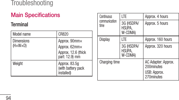
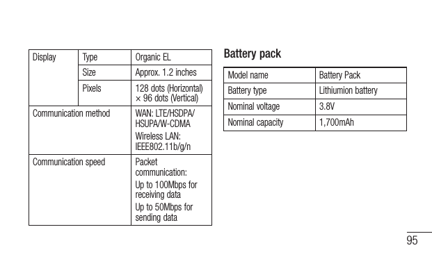
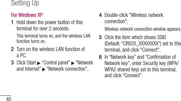
LG Electronics USA CR820 WCDMA & LTE Wireless Router with WLAN User Manual
LG Electronics MobileComm USA, Inc. WCDMA & LTE Wireless Router with WLAN
UserManual.wiki
>
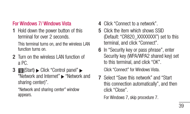
LG Electronics USA
>
CR820 User Manual
User Manual
Navigation menu
Upload a User Manual
Namespaces
Wiki Guide
HTML
PDF
Info
Views
User Manual
Discussion / Help
Navigation

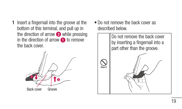
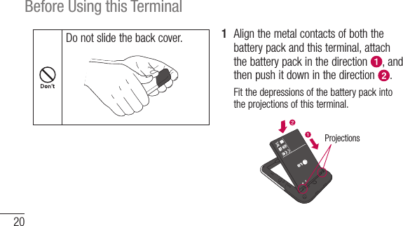
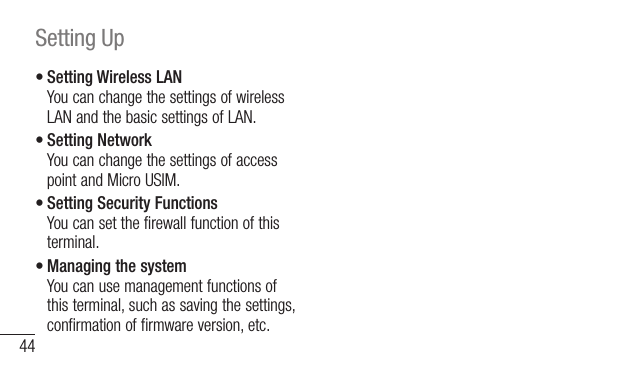
![433 Set the wireless LAN function of the target terminal to ON, and select “WPSPIN” access.Enter the 8-digit WPS PIN on the wireless LAN terminal.4 Enter the 8-digit WPS PIN displayed on the wireless LAN terminal in WPS PIN field of WPS setting page on MOBILE ROUTER CR820 setting page, and click [Apply].When “WPS OK” is displayed, you could access to WPS.Making Other SettingsYou can change the settings of this terminal according to your environment by starting Web browser on the PC connected via wireless LAN and displaying the setting page of this terminal.* You can change this terminal's setting with the console other than a PC, which is equipped with a browser. However, some menus and some browser types may be unavailable.For details, see “Settings”.](https://usermanual.wiki/LG-Electronics-USA/CR820/User-Guide-1936414-Page-45.png)
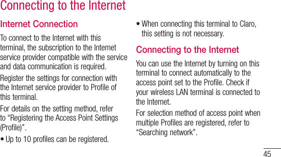
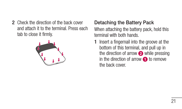
![47This terminal turns on, and the wireless LAN function turns on.2 Turn on a PC and the wireless LAN function.This terminal is connected to the PC via wireless LAN.•Whenconnectingforthefirsttime,wirelessLAN setup is required. For setting up, refer to “Connecting to a Wireless LAN Terminal”.3 Double click the shortcut of MOBILE ROUTER CR820 on the desktop screen, or start a Web browser and enter “http://192.168.2.1/” in the address entry field, then press Enter key.“Login” screen appears.•“192.168.2.1”isthedefaultsettingofthe private IP address of this terminal. When the setting has been changed, enter the private IP address you set.4 Enter “Admin” in [Username] field, enter the log-in password (default: “1234”) in [Password] field, and then click [Login].•In[Language]field,youcanselectalanguage on the setting page.](https://usermanual.wiki/LG-Electronics-USA/CR820/User-Guide-1936414-Page-49.png)
![48SettingsWhen PIN1 code is set, “PIN1 code verification” screen appears.5 When “PIN1 code verification” screen appears, enter PIN1 code in [PIN1 code] field, and then click [Apply].For details on PIN1 code, see “Security Codes”.Click [OK] when a message of PIN1 unlock appears. “Status” screen appears. If there is latest version, a message from web page is displayed on “Status” screen. For updating procedure, see “Updating Software”.](https://usermanual.wiki/LG-Electronics-USA/CR820/User-Guide-1936414-Page-50.png)
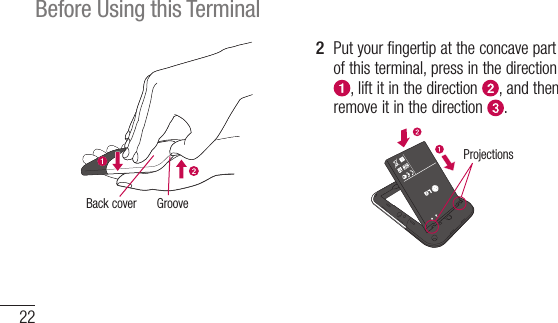
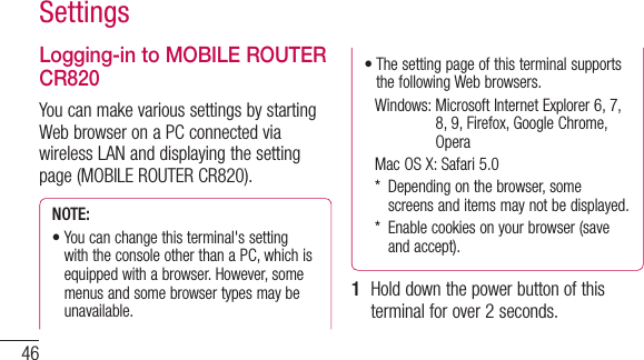
![49NOTE: For your security, it is recommended to change the default setting of log-in password. For details, see “Changing Login Password (Modify password)”.The Setting Page Screen Top menuClick a menu item to switch the setting page. You can select the following items.•STATUS•WLAN•NETWORK•SECURITY•SYSTEMThe submenu appears for some items, and you can switch the setting screen. [Logout]Click to log out from the setting page.](https://usermanual.wiki/LG-Electronics-USA/CR820/User-Guide-1936414-Page-51.png)
![50Settings Setting screenThe setting items for the function selected from the menu items appear. Click to edit the setting. Click to refresh the information on the “Status” screen.Confirming Connection/Setting Conditions of this Terminal1 Click [STATUS] in the top menu.“Status” screen appears.•Click[Refresh]torefreshtheinformation.](https://usermanual.wiki/LG-Electronics-USA/CR820/User-Guide-1936414-Page-52.png)
![52SettingsSetting Wireless LANNOTE: When using wireless LAN overseas, check the available frequency band, laws, regulations or other conditions of the country beforehand.Setting Basic Functions of Wireless LAN1 In the top menu, click [WLAN].2 In the submenu, click [Basic Setting].3 On the setting screen, set the required items.SSID (Default: CR820_XXXXXXXX) Set the network name (SSID) of the wireless LAN. You can enter up to 32 letters with one-byte alphanumeric, “-(hyphen)” and “_(under bar)”.Country (Default: CHILE) Select a country name where this terminal is used. (This field specifies the range of Wlan](https://usermanual.wiki/LG-Electronics-USA/CR820/User-Guide-1936414-Page-54.png)
![53channel.)Channel (Default: Auto) Select a channel of wireless LAN.IEEE802.11 Mode: (Default: 802.11b/g/n) Select an operation mode of wireless LAN.- 802.11b/g/n- 802.11b/g - Only 802.11b- Only 802.11g- Only 802.11n(When the security mode is set to “WEP”, or when the mode is set to “WPA-PSK” or “WPA2-PSK” and “TKIP” is selected, “Only 802.11n” or “802.11b/g/n” cannot be selected.)SSID Broadcast (Default: Enable) Select whether to display SSID on the wireless LAN terminal.- Enable: SSID is displayed- Disable: SSID is not displayedPrivacy separator (Default: Disable)Select whether to prohibit communication between wireless LAN terminals.- Enable: Communication is prohibited- Disable: Communication is not prohibited4 Click [Apply] to save the setting.](https://usermanual.wiki/LG-Electronics-USA/CR820/User-Guide-1936414-Page-55.png)
![54SettingsSetting Wi-Fi auto off Function1 In the top menu, click [WLAN].2 In the submenu, click [Wi-Fi auto off].3 On the setting screen, set the required items.Wi-Fi auto off (Default: Enable) Select whether to set the wireless LAN function to off automatically and power saving mode when no client connection is made in a certain period.- Enable: The wireless LAN function is set to off- Disable: The wireless LAN function is not set to off• When Enable is set Wi-Fi off time (min) (Default: 10)When “Enable” is set to Wi-Fi auto off, select the time (minutes) to set automatically to off.](https://usermanual.wiki/LG-Electronics-USA/CR820/User-Guide-1936414-Page-56.png)
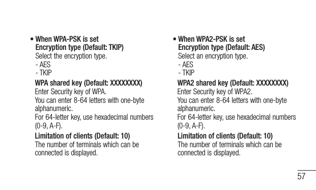
![55- 10- 30- 604 Click [Apply] to save the setting.Setting Security Mode of Wireless LAN1 In the top menu, click [WLAN].2 In the submenu, click [Security].3 On the setting screen, set the required items.Security mode (Default: WPA/WPA2-PSK mixed) Select the security mode of wireless LAN.- Open- WEP- WPA-PSK](https://usermanual.wiki/LG-Electronics-USA/CR820/User-Guide-1936414-Page-57.png)
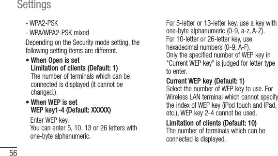
![58Settings• When WPA/WPA2-PSK mixed is set WPA/WPA2 shared key (Default: P40) Enter Security key of WPA/WPA2. You can enter 8-64 letters with one-byte alphanumeric. For 64-letter key, use hexadecimal numbers (0-9, A-F). Limitation of clients (Default: 10) The number of terminals which can be connected is displayed.4 Click [Apply] to save the setting.Setting WPS FunctionNOTE: WPS Function cannot be used when “WEP” is set for “Security”.1 In the top menu, click [WLAN].2 In the submenu, click [WPS].3 On the setting screen, set the required items.](https://usermanual.wiki/LG-Electronics-USA/CR820/User-Guide-1936414-Page-60.png)
![59WPS (Default: Enable) Select whether to use WPS function. - Enable: WPS function is used - Disable: WPS function is not used• When Enable is setWPS type (Default: Push button) Select a type of WPS function.- Enable only: When connect with WPS type after pressing the WPS button of this terminal (WPS function is not activated if you press [Apply] button.)- Push button: When you use the WPS button or connect with WPS type after clicking [Apply] button- WPS PIN: When you connect by entering the PIN code (8-digit number) for WPS WPS PIN Enter the specified PIN code.4 Click [Apply] to save the selected WPS setting.The saved WPS setting is valid even after restarting of this terminal.Setting MAC Address Filter1 In the top menu, click [WLAN].2 In the submenu, click [MAC address filter].3 On the setting screen, set the required items.](https://usermanual.wiki/LG-Electronics-USA/CR820/User-Guide-1936414-Page-61.png)
![60SettingsRestrict mode (Default: Disable) Select an operation mode of MAC address filter function.- Disable: MAC address filter is not used- Allow: Allows the connection only to this terminal with the specified MAC address- Deny: Prohibits the connection to this terminal with the specified MAC address• When Allow or Deny is setMac addresses entry field appears. Enter the specified terminal's MAC address. You can specify up to 10 MAC addresses.4 Click [Apply] to save the setting.Setting DHCP Function1 In the top menu, click [WLAN].2 In the submenu, click [DHCP].3 On the setting screen, set the required items.](https://usermanual.wiki/LG-Electronics-USA/CR820/User-Guide-1936414-Page-62.png)
![61IP address (Default: 192.168.2.1) Set private IP address of this terminal.Subnet mask (Default: 255.255.255.0) Set subnet mask of LAN.DHCP server (Default: Enable) Select whether to use DHCP function.- Enable: DHCP function is used- Disable: DHCP function is not used• When Enable is setStart IP address (Default: 192.168.2.2) Set the minimum IP address assigned to this terminal.End IP address (Default: 192.168.2.99) Set the maximum IP address assigned to this terminal.Primary DNS (Default: 192.168.2.1) Set IP address of primary DNS server.Secondary DNS (Default: 0.0.0.0) Set IP address of secondary DNS server.4 Click [Apply] to save the setting.](https://usermanual.wiki/LG-Electronics-USA/CR820/User-Guide-1936414-Page-63.png)
![62SettingsConfirming Connected Clients1 In the top menu, click [WLAN].2 In the submenu, click [Connected clients].3 The connected terminal's information appears.•Click[Refresh]torefreshtheinformation.4 To disconnect, click in the “Disconnect” field.Setting UPnP FunctionTo use the application using the UPnP function, set to “Enable” the UPnP function.1 In the top menu, click [WLAN].2 In the submenu, click [UPnP].3 On the setting screen, set the required items.](https://usermanual.wiki/LG-Electronics-USA/CR820/User-Guide-1936414-Page-64.png)
![63UPnP (Default: Disable)Select whether to use the UPnP function.- Enable: UPnP function is used- Disable: UPnP function is not used4 Click [Apply] to save the setting.Setting NetworkSetting Network mode Function1 In the top menu, click [NETWORK].2 In the submenu, click [Network mode].3 On the setting screen, set the required items.Band (Default: Auto)- Auto: Connect the LTE network or the 3G network automatically.- LTE only: Connect the LTE network only.- 3G only: Connect the 3G network only.](https://usermanual.wiki/LG-Electronics-USA/CR820/User-Guide-1936414-Page-65.png)
![64Settings4 Click [Apply] to save the setting.Selecting a networkYou can specify the network.1 In the top menu, click [NETWORK].2 In the submenu, click [Searching network].3 On the setting screen, set the required items. Mode (Default: Auto) Select whether to specify the network.- Auto: The network to connect is automatically selected.- Manual: Select when you specify the network. Click [Apply] to search the available network and register it to [Operators].](https://usermanual.wiki/LG-Electronics-USA/CR820/User-Guide-1936414-Page-66.png)
![65• When Manual is set Operators (Default: none) Select a network to connect.4 Click [Apply] to save the setting.Registering the Access Point SettingsRegister, edit or delete the access point settings. You can register up to 10 access points.•By default, the setting for Claro is registered and you cannot delete it. When using Claro, the following setting is not necessary.1 In the top menu, click [NETWORK].2 In the submenu, click [Profile].3 To register a new access point, click [Add New].](https://usermanual.wiki/LG-Electronics-USA/CR820/User-Guide-1936414-Page-67.png)
![66Settings• To edit an existing access point In [Current profile], select an access point to edit. Follow Procedure 4. Follow Procedure 6.• To delete an existing access point In [Current profile], select an access point to delete. Click [Delete]. Click [OK].4 On the setting screen, set the required items.Profile name (Default: clarochile) Enter an access point name. You can enter up to 15 letters with one-byte alphanumeric.APN (Default: bam.clarochile.cl) Enter APN. You can enter up to 99 letters with one-byte alphanumeric, “- (hyphen)”, “@ (at mark)”, “. (period)” and “_ (under bar)”.Username (Default: None) Enter the user name specified by the provider. You can enter up to 64 letters with one-byte alphanumeric, “- (hyphen)”, “@ (at mark)”, “. (period)” and “_ (under bar)”.Password (Default: None)Enter the password specified by the provider. You can enter up to 32 letters with one-byte](https://usermanual.wiki/LG-Electronics-USA/CR820/User-Guide-1936414-Page-68.png)
![67alphanumeric, “- (hyphen)”, “@ (at mark)”, “. (period)” and “_ (under bar)”.Authentication (Default: CHAP) Select the authentication method of the access point.- None- PAP- CHAP5 To register a new access point, click [Save].6 Click [Apply] to save the setting.Protecting the Terminal with the Security CodeWhen this function is set, network communication is locked and entering the security code (PIN1 code) is required when logging in to the setting page.1 In the top menu, click [NETWORK].2 In the submenu, click [PIN1 lock].3 On the setting screen, set the required items.](https://usermanual.wiki/LG-Electronics-USA/CR820/User-Guide-1936414-Page-69.png)
![68SettingsPIN1 lock status The current setting condition is displayed.- Enable: PIN1 lock is set- Disable: PIN1 lock is canceled• When Enable is set PIN1 code to disable Enter PIN1 code set to the Micro USIM card.• When Disable is set PIN1 code to enable Enter PIN1 code set to the Micro USIM card.4 Click [Apply].5 When “Enabled” is set, hold down the power button for over 2 seconds to turn the power off, and then turn on again.](https://usermanual.wiki/LG-Electronics-USA/CR820/User-Guide-1936414-Page-70.png)
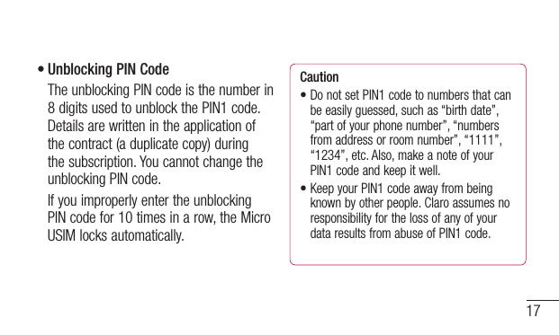
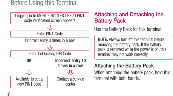
![69Unlocking PIN LockIf you improperly enter the PIN1 code for 3 times in a row, further entry is locked automatically. In this case, enter “Unblocking PIN Code” to unlock.1 Enter the unblocking PIN code in [PUK code] field.2 Enter the new PIN1 code in the [New PIN1 code] field.3 In [Confirm PIN1 code] field, enter the same PIN1 code as [New PIN1 code] for confirmation.4 Click [Apply].Changing the Security Code You can change the security code (PIN1 code).•Changingsecuritycode(PIN1code)isavailable only when PIN1 lock is set to “Enabled”.1 In the top menu, click [NETWORK].2 In the submenu, click [Modify PIN1 code].3 On the setting screen, set the required items.](https://usermanual.wiki/LG-Electronics-USA/CR820/User-Guide-1936414-Page-71.png)
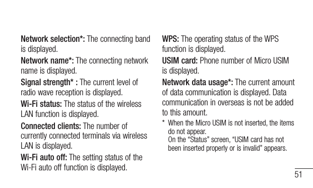
![70SettingsCurrent PIN1 code Enter PIN1 code set to the Micro USIM card.New PIN1 code Enter the new PIN1 code.Confirm PIN1 code Enter the same code as [New PIN1 code] for confirmation.4 Click [Apply].PIN1 code is changed.Displaying Network data usageThe amount of data communication is displayed. Data communication in overseas is not be added to this amount. Also, the amount of data communication in the international roaming area is not displayed.1 In the top menu, click [NETWORK].2 In the submenu, click [Network data usage].](https://usermanual.wiki/LG-Electronics-USA/CR820/User-Guide-1936414-Page-72.png)
![713 On the setting screen, set the required items.Current data usage Click [Refresh] to see the latest information. Click [Reset] to reset the information of usage.The usage is automatically reset in the following cases.- When the Micro USIM is replacedMaximum data size (Default: Disable)Select from KB, MB and GB, and enter the valid value*.* Valid value: Positive integer from 1 to 1024 Not available: Negative number, 0, decimal point and anything other than the valid value* Even if maximum data size is set, data communication will not stop when data usage is over the maximum data size. It is only for your reference.](https://usermanual.wiki/LG-Electronics-USA/CR820/User-Guide-1936414-Page-73.png)
![72SettingsDisplay on modem (Default: Enable)Enable: The amount of data communication is displayed on the display of this terminal.Disable: The amount of data communication is not displayed on the display of this terminal.4 Click [Apply] to save the setting.Setting Security FunctionsUsing Firewall FunctionUnauthorized access via the Internet can be blocked by using the Firewall function. Also, you can set IP filter.1 In the top menu, click [SECURITY].2 In the submenu, click [Firewall].3 On the setting screen, set the required items.](https://usermanual.wiki/LG-Electronics-USA/CR820/User-Guide-1936414-Page-74.png)
![73Firewall (Default: Disable)Set whether to activate the Firewall function.- Enable: Firewall function is activated. You can set IP filter.- Disable: Firewall function is deactivated.• When Enable is set You can set IP filter.IP address When registering IP filter, enter source or destination IP address.Direction (Default: Source) Specify the direction of communication to interrupt.- Source: Interrupt the access from the specified IP address.- Destination: Interrupt the access to the specified IP address.IP address filter list List of registered IP filter appears.- : Delete registered IP filter.4 Click [Apply].Discarding WAN PingYou can discard the Ping request to access from WAN to prevent answering and block the IP information leakage from this terminal and LAN terminals.](https://usermanual.wiki/LG-Electronics-USA/CR820/User-Guide-1936414-Page-75.png)
![74Settings1 In the top menu, click [SECURITY].2 In the submenu, click [WAN Ping blocking].3 On the setting screen, set the required items.WAN Ping blocking (Default: Disable) Set whether to activate the WAN Ping blocking function.- Enable: Activate the WAN Ping blocking function.- Disable: Deactivate the WAN Ping blocking function.4 Click [Apply].Managing the SystemChanging Log-in PasswordYou can change the log-in password of the setting page. You can enter only a 4-digit number as a password.](https://usermanual.wiki/LG-Electronics-USA/CR820/User-Guide-1936414-Page-76.png)
![751 In the top menu, click [SYSTEM].2 In the submenu, click [Modify password].3 On the setting screen, set the required items.Current password Enter the current password.New password Enter the new password.Confirm password Enter the same password as [New password] for confirmation.4 Click [Apply].The message “Password is changed successfully” appears.5 Click [OK].](https://usermanual.wiki/LG-Electronics-USA/CR820/User-Guide-1936414-Page-77.png)
![76SettingsSaving/Restoring the Setting DataAll setting data can be saved to a PC on which the setting page is opened. Also, saved setting data can be restored in this terminal.1 In the top menu, click [SYSTEM].2 In the submenu, click [Backup & Restore].3 In the setting screen, make the following procedures.Backup to file Click [Backup], specify the file name (Default: webcm_config.cfg) and save the current setting.* Depending on the browser, the file name cannot be specified.](https://usermanual.wiki/LG-Electronics-USA/CR820/User-Guide-1936414-Page-78.png)
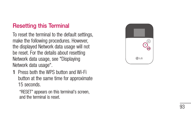
![77Restore from file Click [Refer to...] and specify the file to restore.4 Click [Apply].Resetting the SettingsYou can reset all settings of the setting page to default. However, the amount of data communication which is displayed on the display cannot be reset. For resetting the amount of data communication, see “Displaying Network data usage”.•You can also reset the settings by pressing the buttons on this terminal. 1 In the top menu, click [SYSTEM].2 In the submenu, click [Reset].3 Click [Reset].4 Click [OK].Log out from the setting page and the communication is disconnected.](https://usermanual.wiki/LG-Electronics-USA/CR820/User-Guide-1936414-Page-79.png)
![78SettingsConfirming the Version Information1 In the top menu, click [SYSTEM].2 In the submenu, click [Version].The version information of firmware and this terminal appears.3 Make setting for Software Update. Automatically check new S/W (Default: ON)- ON: Check the update file automatically.- OFF: Check the update file manually.• When ON is set The confirmation message for software update appears each time you log in. To make the message not to appear, set to “OFF”.• When OFF is set Click [Check now] to check if you have any update files, and a message appears when a new file exists. For update procedure, see “Updating Software”.4 When you have changed software update setting, click [Apply].](https://usermanual.wiki/LG-Electronics-USA/CR820/User-Guide-1936414-Page-80.png)
![79Displaying the Inquiries1 In the top menu, click [SYSTEM].2 In the submenu, click [Help].The information of the inquiry website, phone number and the URL of Instruction Manual (PDF) appears.](https://usermanual.wiki/LG-Electronics-USA/CR820/User-Guide-1936414-Page-81.png)
![80Overseas UseSetting the Searching Methods for Available Networks and Access PointSet an available network (communication operator) at your current location manually (Manual setting is possible only for using overseas). You can make settings related to network by logging-in to the setting page.1 Log in to the setting page.For details, see “Logging-in to MOBILE ROUTER CR820”.2 Click [NETWORK] in the top menu.3 Click [Searching network] in submenu, and set each items.](https://usermanual.wiki/LG-Electronics-USA/CR820/User-Guide-1936414-Page-82.png)
![81Mode* Select whether to specify the access point network.- Auto: Network that can be connected is automatically selected.- Manual: Select to specify the network. Click [Apply] to search the available access point and register it to [Operators].4 Click [Apply] to save the setting contents.5 Click [Logout].NOTE: While using overseas- Some communication services may not be available depending on the overseas carrier or network.](https://usermanual.wiki/LG-Electronics-USA/CR820/User-Guide-1936414-Page-83.png)
![87Symptom CheckCannot connect the wireless LAN terminalIf the security mode other than WEP2-PSK is set to this terminal, you need to make the same settings for the target wireless LAN terminal. For details, refer to the instruction manual of your wireless LAN terminal.• Example: Security mode is WEP For Windows 7 Click (Start) “Control panel)” “Network and Internet” “Network and Sharing Center” “Manage Wireless Networks” Right click the name of this terminal and “Properties” “Security” tab Set following: - Security Type: no authentication - Encryption Type: WEP - Network Security Key: WEP key of this terminal whose number is selected in Key indexSymptom CheckCannot connect the wireless LAN terminal• Example: Security mode is WEP For Mac OS 10.7 [Apple] menu [System Preferences...] [ [Network] Select [Wi-Fi] on the left screen [Edit network] on [Network] [ + ] Enter any name in [Untitled] [OK] Check [Display Wi-Fi status on menu bar] [Details] Select [Wi-Fi] on tab located in the upper of screen [ + ] Enter network name Select [WEP] in [Security] Enter WEP key 1 of this terminal in [Password] [OK] [OK] Check [Wi-Fi ON] if the status is [OFF], and [Apply]](https://usermanual.wiki/LG-Electronics-USA/CR820/User-Guide-1936414-Page-89.png)
![91Error MessagesThe following messages may appear when using the setting page (MOBILE ROUTER CR820).Error Messages DescriptionThe password you entered is not correct.An incorrect password is entered for log-in. Click [OK] and enter the correct password.The PIN1 code you entered is not correct.An incorrect PIN1 code is entered. Click [OK] and enter the correct PIN1 code.Error Messages DescriptionPIN1 code is blocked.PIN1 code is locked because PIN1 code has been improperly entered 3 times in a row. Click [OK], enter unblocking PIN code in [PUK code] and new PIN1 code in [New PIN1 code] and [Confirm PIN1 code]. Click [Apply].The PUK code you entered is not correct.An incorrect unblocking PIN1 code is entered. Click [OK] and enter the correct unblocking PIN code.](https://usermanual.wiki/LG-Electronics-USA/CR820/User-Guide-1936414-Page-93.png)