LG Electronics USA CR820 WCDMA & LTE Wireless Router with WLAN User Manual
LG Electronics MobileComm USA, Inc. WCDMA & LTE Wireless Router with WLAN
User Manual

ENGLISH
User Guide
CR820
MFL67846801 (1.0) www.lg.com
CR820
User Guide
ENGLISH

2
Supplied Accessories .....................................3
Precautions....................................................4
Before Using this Terminal .............................8
Setting Up ....................................................34
Connecting to the Internet ...........................45
Settings .......................................................46
Overseas Use ...............................................80
Troubleshooting ...........................................82
Guidelines for safe and efficient use ............96
Contents
3
CR820 Terminal
(including the warranty)
CR820 INSTRUCTION
MANUAL
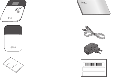
Back Cover Data cable
Travel Adapter
Battery Pack IMEI Label
SSID: CR820_EF31C1E0
Security Key: B83A3F60
351876050000001
*351876050000001*
Supplied Accessories

4
Precautions
Technical data
Ambient temperatures
Max: +35°C (discharging), +45°C (charging)
Min: 0°C
Battery information and care
•You do not need to completely discharge
the battery before recharging. Unlike
other battery systems, there is no
memory effect that could compromise the
battery's performance.
•Use only LG batteries and chargers. LG
chargers are designed to maximise the
battery life.
•Do not disassemble or short-circuit the
battery.
•Keep the metal contacts of the battery
clean.

5
•Replace the battery when it no longer
provides acceptable performance. The
battery pack may be recharged hundreds
of times before it needs replacing.
•Recharge the battery if it has not been
used for a long time to maximise
usability.
•Do not expose the battery charger to
direct sunlight or use it in high humidity,
such as in the bathroom.
•Do not leave the battery in hot or cold
places, as this may deteriorate battery
performance.
•There is risk of explosion if the battery is
replaced with an incorrect type.
•Dispose of used batteries according to
the manufacturer's instructions. Please
recycle when possible. Do not dispose as
household waste.
•If you need to replace the battery, take it
to the nearest authorised LG Electronics
service point or dealer for assistance.
•Always unplug the charger from the wall
socket after the phone is fully charged to
save unnecessary power consumption of
the charger.

6
Precautions
•Actual battery life will depend on network
configuration, product settings, usage
patterns, battery and environmental
conditions.
•Make sure that no sharp-edged items
such as animal’s teeth or nails, come
into contact with the battery. This could
cause a fire.
Adapter
•Charge the battery pack in a place with
an ambient temperature between 0°C
and 45°C.
•Do not charge the battery pack in the
following areas.
- In areas of excessive humidity, dust or vibration
- Near land-line phones, TVs or radios
•It is normal for the adapters to become
warm while using or charging the
terminal. You can continue to use it.
•Use the DC adapter only when the car
engine is running.
- Otherwise, the car battery may be exhausted.
•Do not give a strong impact to the adapter.
Also, do not deform the charging terminals.
Malfunction may result.

7
Micro USIM
•Do not put excessive force on the Micro
USIM when inserting or removing it into
this terminal.
•Do not insert and use the Micro USIM
with another IC card reader/writer. Please
note that you are wholly liable for any
damage or malfunction as a result of
such action.
•Always keep the IC portion of the Micro
USIM clean.
•Clean the Micro USIM with a soft, dry
cloth (Lens cleaning cloth).
•Be sure to keep a separate note of the
information registered to this terminal.
Claro assumes no responsibility for the loss of
any of your data.
•Visit service center to return the
expended Micro USIM for the
environmental purpose.
•Do not scratch, touch carelessly or short
circuit the IC portion.
Data loss or malfunction may result.
•Do not drop or give shock to the Micro
USIM.
Malfunction may result.
8
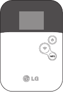
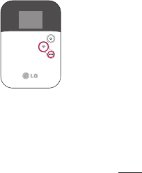
Before Using this Terminal
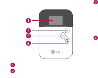
Names of Parts and Functions
Display
Power button: Hold down the button for over
2 seconds to turn on or off.
Wi-Fi button: Hold down the button for over
2 seconds to set/cancel power saving mode.
During power saving mode, wireless LAN
function and network communication function
are off. When the display has gone off, press
the Power button to lighten the display, then
press the Wi-Fi button.
WPS button: Hold down the button for over
2 seconds to connect the other wireless LAN
device to the wireless LAN of this terminal
using WPS function (Unavailable when WEP
is set). When the display has gone off, press
the Power button to lighten the display, then
press the WPS button.
9
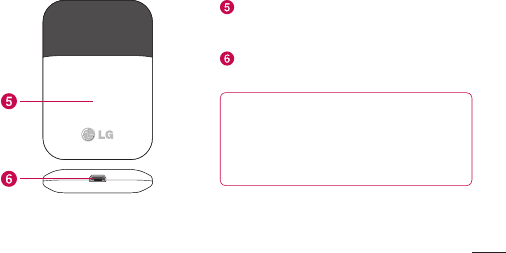
Back cover: Removing the back cover, the
Micro USIM slot guide is under the battery
pack.
External connector: This connects to AC
Adapter or microUSB Connection Cable.
NOTE: When this terminal is put on the
metal objects such as a steel desk or table,
the performance of the antenna is affected
and the communication speed may become
lower.
10
Before Using this Terminal
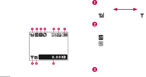
Display Overview
The signs (icons) that appear on the display
indicate these states (press the power
button to display the icons):
Levels of radio wave reception
Strong Weak
Types of networks available during
connection
LTE
3G (HSDPA/HSUPA, W-CDMA)
Internet connection is unavailable when
an icon shows not connected appears
on the display of this terminal.
Activating global roaming
11
States of network connection
Connected
Not connected
Pending state of connection
WPS function available
Wi-Fi auto off function set
Battery level
High Low
Blinking: The battery is almost
exhausted. Charge the battery.
Wireless LAN function ON
It disappears when wireless LAN
function is OFF.
Number of connecting terminals to
wireless LAN
Network data usage
The amount of data communication
is displayed. Data communication
in overseas is not be added to this
amount. Also, the amount of data
communication within the international
roaming area is not displayed.
12
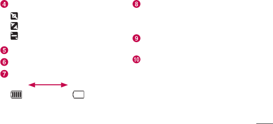
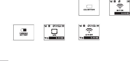
Before Using this Terminal
•Indicators
The display shows the charging state of
battery pack, wireless LAN states, name
of the connecting network, etc.
(Examples are shown below.)
Charging Activating WPS
function
Battery is exhausted Activating Wi-Fi
Disconnecting Wi-Fi

13
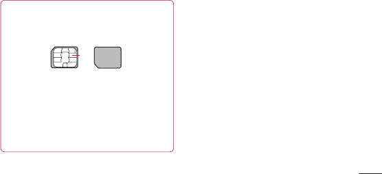
Using Micro USIM
A Micro USIM is an IC card that stores
personal information such as your phone
number. Without the Micro USIM installed
in this terminal, you cannot use data
communication. For details on handling
the Micro USIM, refer to the Micro USIM
manual.
Only the Micro USIM can be used in this
terminal.
Inserting the Micro USIM
When inserting the Micro USIM, hold this
terminal with both hands.
•Turn the power off and remove the
battery pack before attaching the Micro
USIM.
1
With the IC chip side down, insert a
Micro USIM under the Micro USIM slot
guide in the direction of arrow.
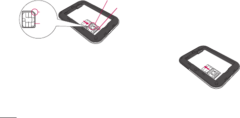
14
Before Using this Terminal
Notch
Micro USIM slot guide
Notch
IC
(gold)
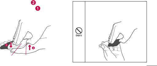
Removing the Micro USIM
When removing the Micro USIM, hold this
terminal with both hands.
•Turn the power off and remove the
battery pack before removing the Micro
USIM.
1
Slide the Micro USIM in the direction of
arrow to remove.
15
NOTE
•DonotlosetheremovedMicroUSIM.
•CheckbothsidesoftheMicroUSIM.
IC
•Becarefulnottotouchorscratchthe
Micro USIM IC.
•InsertingaMicroUSIMinthereverse
direction may cause malfunction.
•InsertingorremovingtheMicroUSIMwith
an excessive force
Security Codes
A Micro USIM has PIN1 (Personal
Identification Number) code.
The PIN1 code is a 4 to 8-digit security
code to be entered every time this terminal
is turned on for user verification to prevent
any unauthorized use by others.

16
Before Using this Terminal
If your Micro USIM is set to require a
PIN1 code, data communication cannot
be performed until the PIN1 code is
entered.
Use the Micro USIM before verifying the
PIN1 code, or set the Micro USIM not to
verify the PIN1 code in advance.
•Changing PIN1 Code
You can change the PIN1 code to any
number. To prevent any unauthorized use
by third parties, change it to your original
number.
If you improperly enter the PIN1 code for
3 times in a row, further entry is locked
automatically (PIN1 Lock), so be sure to
keep a separate note of the numbers you
set.
- “Changing the Security Code (Modify
PIN code)”

17
•Unblocking PIN Code
The unblocking PIN code is the number in
8 digits used to unblock the PIN1 code.
Details are written in the application of
the contract (a duplicate copy) during
the subscription. You cannot change the
unblocking PIN code.
If you improperly enter the unblocking
PIN code for 10 times in a row, the Micro
USIM locks automatically.
Caution
•DonotsetPIN1codetonumbersthatcan
be easily guessed, such as “birth date”,
“part of your phone number”, “numbers
from address or room number”, “1111”,
“1234”, etc. Also, make a note of your
PIN1 code and keep it well.
•KeepyourPIN1codeawayfrombeing
known by other people. Claro assumes no
responsibility for the loss of any of your
data results from abuse of PIN1 code.
18
Before Using this Terminal
Logging-in to MOBILE ROUTER CR820 PIN1
code Verification screen appears
Enter PIN1 Code
Incorrect entry 3 times in a row
Enter Unblocking PIN Code
OK
Available to set a
new PIN1 code
Incorrect entry 10
times in a row
Contact a service
center
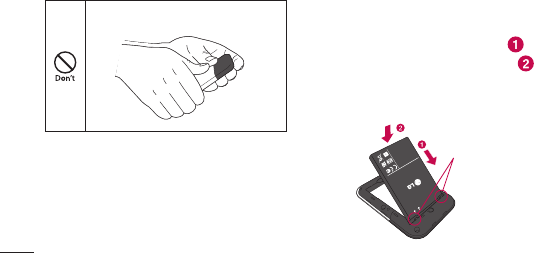
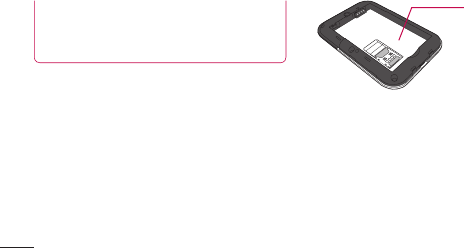
Attaching and Detaching the
Battery Pack
Use the Battery Pack for this terminal.
NOTE: Always turn off this terminal before
removing the battery pack. If the battery
pack is removed while the power is on, this
terminal may not work correctly.
Attaching the Battery Pack
When attaching the battery pack, hold this
terminal with both hands.
19
1
Insert a fingernail into the groove at the
bottom of this terminal, and pull up in
the direction of arrow while pressing
in the direction of arrow to remove
the back cover.
Back cover Groove
•Do not remove the back cover as
described below.
Do not remove the back cover
by inserting a fingernail into a
part other than the groove.
20
Before Using this Terminal
Do not slide the back cover.
1
Align the metal contacts of both the
battery pack and this terminal, attach
the battery pack in the direction , and
then push it down in the direction .
Fit the depressions of the battery pack into
the projections of this terminal.
Projections
21
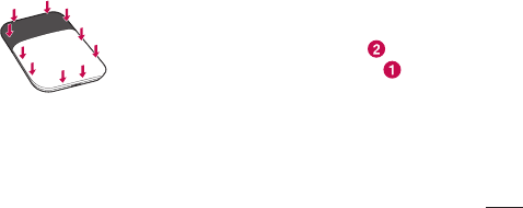
2
Check the direction of the back cover
and attach it to the terminal. Press each
tab to close it firmly.
Detaching the Battery Pack
When attaching the battery pack, hold this
terminal with both hands.
1
Insert a fingernail into the groove at the
bottom of this terminal, and pull up in
the direction of arrow while pressing
in the direction of arrow to remove
the back cover.
22
Before Using this Terminal
Back cover Groove
2
Put your fingertip at the concave part
of this terminal, press in the direction
, lift it in the direction , and then
remove it in the direction .
Projections
23
3
Check the direction of the back cover
and attach it to the terminal. Press each
tab to close it firmly.
Charging
Battery pack life
•The battery pack is a consumable item.
The usable time decreases every time the
battery pack is recharged.
•When the usable time after each recharging
shortens by approximately half compared to
a new battery pack, it is recommended that
the battery pack be replaced with a new
one as soon as possible. The battery pack
may swell as the battery life is near its end
depending on the battery pack condition,
but it is not a malfunction.

24
Before Using this Terminal
•If you make communication while the
battery pack is being charged, the battery
life may be shortened.
Charging
•To use an AC adapter overseas, the
compatible conversion plug adapter is
required. Do not charge the battery pack
with a transformer designed for overseas
trips.
•To charge the battery pack with the AC
or DC adapter, make sure that the battery
pack is inserted into this terminal.
•Plug or unplug the connector slowly and
securely avoiding excessive force.
•If you start charging the fully drained
battery pack, this terminal may not be
turned on for a while.
•If you make communication while charging,
the inside of this terminal may become
hot and charging may stop. In this case,
end the functions in use and wait until this
terminal becomes cool down, and then try
charging again.
•Depending on the usage condition, charging

25
may stop before the battery level becomes
100%. In this case, remove the battery
pack and attach it again to continue
charging.
•Do not remove the battery pack while
charging. If the battery pack is removed,
the power does not correctly turn on or
the battery is not correctly charged. In
that case, remove the battery pack and all
cables from this terminal, and reconnect
them.
Approximate battery pack usage &
charging time
The usage time may vary depending on the
operating environment and the battery pack
deterioration.
Continuous
communication
time
LTE Approx.
4 hours
3G (HSDPA/
HSUPA,
W-CDMA)
Approx.
5 hours

26
Before Using this Terminal
Continuous
stand-by time
LTE Approx.
160 hours
3G (HSDPA/
HSUPA,
W-CDMA)
Approx.
320 hours
Battery pack
charging time
AC Adapter Approx.
200 minutes
USB Approx.
270 minutes
•Continuous communication time is the
approximate usage time when you can
normally send and receive radio waves.
•Continuous stand-by time is approximate
usage time when moving with normal
radio wave reception level.
•Communication time or operating time
may be reduced by half depending
on the battery level, set functions,
operating environment such as ambient
temperature, or radio wave reception
level (poor or weak radio wave reception
level).
27
•Depending on network conditions in
the country you stay, usage time may
become shorter than the described
values.
•The estimated charging time is the
duration of time to charge a fully drained
battery pack with this terminal turned off.
The charging time becomes longer with
this terminal turned on.
Turning Power On/Off
Turning Power On
1
When this terminal is turned off, hold
down the power button for over 2
seconds.
28
Before Using this Terminal
Turning Power Off
1
When this terminal is turned on, hold
down the power button for over 2
seconds.
Available Communications
Basic Usage
You can perform data communication at
a speed of up to 100Mbps* for receiving
data and up to 50Mbps* for sending data
by connecting up to 10 Wi-Fi devices
compatible with wireless LAN function.
* Communication speed is theoretical
values when sending and receiving data
which does not show the actual ones. The
actual communication speed depends on
communication environment and network
congestion.
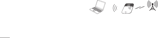
Network
Wireless LAN
CR820PC, game console,
etc.

29
Wireless LAN
You can connect up to 10 Wi-Fi devices
compatible with wireless LAN (IEEE 802.11
b/g/n) simultaneously.
•This terminal supports WPS function.
When your wireless LAN terminal
supports WPS function, you can set up
the wireless LAN connection easily.
•This terminal cannot connect to a
wireless LAN access point.
NOTE:
•Notethathighcommunicationfeesare
charged when performing communications
with large amount of data such as
browsing websites with many graphics or
downloading data.
•Datacommunicationmaytakemore
time or become difficult to connect
depending on the network congestion.
For customers who use a large amount
of data communication, it may have
difficulties in sending and receiving data
on time. Also, data communication may
get disconnected when a large amount

30
Before Using this Terminal
of data communication occurs at a time
or within a certain period of time, when
being connected for a long time or when
connecting several times in a row within a
certain period of time.
•ThisterminaldoesnotsupportRemote
Wakeup.
•ThisterminaldoesnotsupportFAX
communication.
Usage Notes
•User authentication to access
networks
The ID and password will be provided
by the network administrator of your ISP
or the access point. For details, contact
your provider or access point network
administrator.
Internet connection is unavailable when
“Not connected” icon appears on the
display of this terminal.
31
•Requirements for communication
The following conditions must be met
to perform communications using this
terminal. However, a connection may not
be established if traffic is heavy at the
base station or if radio waves are weak.
- This terminal must be in service area.
- The access point corresponds to the
data communication.
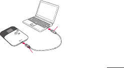
Attaching and Detaching this
Terminal to/from a PC
Attach this terminal to a PC to charge this
terminal with microUSB Connection Cable.
Attaching to a PC
USB
connector
microUSB connector
(with the inscribed B side up)

32
Before Using this Terminal
1
Turn on a PC.
2
With the inscribed B side up, insert the
microUSB connector of the microUSB
Connection Cable straight to the external
connector of this terminal.
3
Insert the other connector of microUSB
Connection Cable to the USB port of
the PC.
•Forthefirsttimeconnectionafter
purchasing, the CR820 driver setup
screen appears by zero-install function
only for Windows version. Follow the
onscreen instructions to install the driver.*
The driver is necessary only when
updating software. After installation,
the shortcut of Connection Manager is
created on the desktop screen.
Depending on the OS settings,
“Auto start” screen may appear. When
the screen appears, select LGERouter_
ModemDriver and choose Setup
Language either "English" or "Polish" and
click "Next".
* Do not cancel the driver installation halfway
or remove this terminal. Without the driver,
Software update cannot be performed.

33
Detaching from a PC
Remove microUSB Connection Cable.

34
Setting Up
Before using this terminal, make settings to
connect your wireless LAN terminal to this
terminal's wireless LAN.
You can also change the wireless LAN
and other settings according to your
environment.
Operating Environments
Use this terminal under the following
operating environments.
Item Requirement
PC Main
Unit
PC/AT compatible computer and
Mac More than 800 × 600 dots
for display resolution and High
Color 16 bits are recommended
OS
*1
WindowsXPSP3
Windows Vista SP2
Windows 7 SP1
MacOSX10.6.8/10.7.3
*3
Setting Up

35
Item Requirement
Required
Memory
*2
WindowsXP:256MBormore
Windows Vista: 512MB or more
Windows 7: 1GB or more (32bit),
2GB or more (64bit)
MacOSX10.6.8:1GBormore
MacOSX10.7.3:2GBormore
Hard Disk
Space
*2
100MB or more free disk space
*1 Claro does not guarantee the operation
under the environment of OS which is
upgraded, added or modified.
*2 Required memory or available hard disk
space may vary depending on the system
environment of a PC.
*3 This is only for Mac with Intel CPU.
NOTE: The software may not work depending
on your operating system environment and
type of device. Claro does not guarantee any
inquiry or operation other than the operation
environment described in this manual.

36
Setting Up
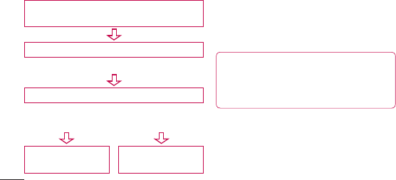
Flow of Setup
Setup is made in the following procedure.
Connect your wireless LAN terminal to this
terminal's wireless LAN
Setting the Internet connection
•ForClaro,thissettingisnotnecessary.
•Forsettingprocedures,see“Registeringthe
Access Point Settings (Profile)”.
NOTE:
To change this terminal's setting, connect
this terminal to a PC, change the setting,
and then connect the other wireless LAN
terminal.
* You can change this terminal's setting
with the console other than a PC, which is
equipped with a browser. However, some
menus and some browser types may be
unavailable.

37
Connecting to a Wireless LAN
Terminal
Setting procedures vary depending on the
wireless LAN you use. The procedures for the
following terminals are described here.
•Windows PC (For Windows 7/Windows Vista)
•WindowsPC(ForWindowsXP)
•Mac
•iPad
•iPod touch
•Nintendo DS
•PSP
•WPS compatible wireless LAN terminal
NOTE:
•Makeoneofthesesettingswhenyou
connect this terminal to each terminal
for the first time. Once you have set, the
terminal connects to it automatically only
by turning power on.
•ToconnecttoawirelessLANwithout
WPS function, entering SSID and Security
key (WPA/WPA2 shared key) set to this
terminal is required. Confirm it in advance.
•Thisterminalcanconnectupto10
wireless LAN terminals simultaneously.
38
Setting Up
•ForWindowsPCandMac,youneedto
login with the user account which has
administrative right beforehand.
•SSID and Security key (WPA/WPA2
shared key) printed area
Check SSID and Security key (WPA/WPA2
shared key) on the included “Wireless
LAN Initialization Sticker”. Also, SSID and
Security key (WPA/WPA2 shared key)
is printed on the sticker inside of this
terminal. Remove the battery pack to see
it.
SECURITY KEY
Connecting to Windows PC
The setting procedure when security mode
of this terminal is set to “WPA2-PSK/AES”
is described here.

39
For Windows 7/ Windows Vista
1
Hold down the power button of this
terminal for over 2 seconds.
This terminal turns on, and the wireless LAN
function turns on.
2
Turn on the wireless LAN function of
a PC.
3
(Start) Click “Control panel”
"Network and Internet” “Network and
sharing center)”.
“Network and sharing center” window
appears.
4
Click “Connect to a network”.
5
Click the item which shows SSID
(Default:“CR820_XXXXXXXX”)settothis
terminal, and click “Connect”.
6
In “Security key or pass phrase”, enter
Security key (WPA/WPA2 shared key) set
to this terminal, and click “OK”.
Click “Connect” for Windows Vista.
7
Select “Save this network” and “Start
this connection automatically”, and then
click “Close”.
For Windows 7, skip procedure 7.

40
Setting Up
For Windows XP
1
Hold down the power button of this
terminal for over 2 seconds.
This terminal turns on, and the wireless LAN
function turns on.
2
Turn on the wireless LAN function of
a PC.
3
Click Start “Control panel” “Network
and Internet” “Network connection”.
4
Double-click "Wireless network
connection".
Wireless network connection window appears.
5
Click the item which shows SSID
(Default:“CR820_XXXXXXXX”)settothis
terminal, and click “Connect".
6
In “Network key” and “Confirmation of
Network key”, enter Security key (WPA/
WPA2 shared key) set to this terminal,
and click “Connect”.

41
Connecting to WPS Compatible
Wireless LAN Terminal
NOTE:
•Settingproceduresvarydependingon
the wireless LAN terminal. Refer to the
instruction manual of your wireless LAN
terminal.
•WhenthePINcodeofWPSfunctionis
specified to your wireless LAN terminal,
you need to select “WPS PIN” in “WPS
type”, and set the specified PIN code to
“WPS PIN” in advance.
•Whenthesecuritymodeofthisterminal
is set to “WEP”, WPS function is not
available.
•When“SSIDBroadcast”is“Disable”,the
WPS function is not activated.
When “WPS type” is “Push button”
1
Hold down the power button of this
terminal for over 2 seconds.
This terminal turns on, and the wireless LAN
function turns on.

42
Setting Up
2
Set the wireless LAN function of the
target terminal to ON, and make the
WPS function setting as required.
The operation varies depending on the
terminal.
3
Perform the connecting operation of the
WPS function on the target terminal.
The operation varies depending on the
terminal.
4
Press the WPS button of this terminal for
over 2 seconds.
5
Follow the onscreen instructions of the
target terminal to on.
The operation varies depending on the
terminal.
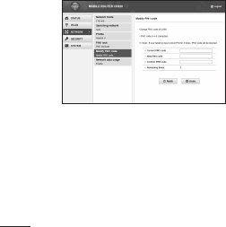
When “WPS type” is “WPS PIN”
1
Hold down the power button of this
terminal for over 2 seconds.
This terminal turns on, and the wireless LAN
function turns on.
2
Start the web browser on PC which
is connected with the wireless LAN,
and login to the setting page (MOBILE
ROUTER CR820).

43
3
Set the wireless LAN function of the
target terminal to ON, and select
“WPSPIN” access.
Enter the 8-digit WPS PIN on the wireless
LAN terminal.
4
Enter the 8-digit WPS PIN displayed on
the wireless LAN terminal in WPS PIN
field of WPS setting page on MOBILE
ROUTER CR820 setting page, and click
[Apply].
When “WPS OK” is displayed, you could
access to WPS.
Making Other Settings
You can change the settings of this terminal
according to your environment by starting
Web browser on the PC connected via
wireless LAN and displaying the setting
page of this terminal.
* You can change this terminal's setting
with the console other than a PC, which is
equipped with a browser. However, some
menus and some browser types may be
unavailable.
For details, see “Settings”.

44
Setting Up
•Setting Wireless LAN
You can change the settings of wireless
LAN and the basic settings of LAN.
•Setting Network
You can change the settings of access
point and Micro USIM.
•Setting Security Functions
You can set the firewall function of this
terminal.
•Managing the system
You can use management functions of
this terminal, such as saving the settings,
confirmation of firmware version, etc.

45
Connecting to the Internet
Internet Connection
To connect to the Internet with this
terminal, the subscription to the Internet
service provider compatible with the service
and data communication is required.
Register the settings for connection with
the Internet service provider to Profile of
this terminal.
For details on the setting method, refer
to “Registering the Access Point Settings
(Profile)”.
•Up to 10 profiles can be registered.
•When connecting this terminal to Claro,
this setting is not necessary.
Connecting to the Internet
You can use the Internet by turning on this
terminal to connect automatically to the
access point set to the Profile. Check if
your wireless LAN terminal is connected to
the Internet.
For selection method of access point when
multiple Profiles are registered, refer to
“Searching network”.

46
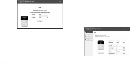
Settings
Logging-in to MOBILE ROUTER
CR820
You can make various settings by starting
Web browser on a PC connected via
wireless LAN and displaying the setting
page (MOBILE ROUTER CR820).
NOTE:
•Youcanchangethisterminal'ssetting
with the console other than a PC, which is
equipped with a browser. However, some
menus and some browser types may be
unavailable.
•Thesettingpageofthisterminalsupports
the following Web browsers.
Windows: Microsoft Internet Explorer 6, 7,
8, 9, Firefox, Google Chrome,
Opera
MacOSX:Safari5.0
* Depending on the browser, some
screens and items may not be displayed.
* Enable cookies on your browser (save
and accept).
1
Hold down the power button of this
terminal for over 2 seconds.

47
This terminal turns on, and the wireless LAN
function turns on.
2
Turn on a PC and the wireless LAN
function.
This terminal is connected to the PC via
wireless LAN.
•Whenconnectingforthefirsttime,wireless
LAN setup is required. For setting up, refer
to “Connecting to a Wireless LAN Terminal”.
3
Double click the shortcut of MOBILE
ROUTER CR820 on the desktop screen,
or start a Web browser and enter
“http://192.168.2.1/” in the address
entry field, then press Enter key.
“Login” screen appears.
•“192.168.2.1”isthedefaultsettingof
the private IP address of this terminal.
When the setting has been changed,
enter the private IP address you set.
4
Enter “Admin” in [Username] field, enter
the log-in password (default: “1234”) in
[Password] field, and then click [Login].
•In[Language]field,youcanselecta
language on the setting page.
48
Settings
When PIN1 code is set, “PIN1 code
verification” screen appears.
5
When “PIN1 code verification” screen
appears, enter PIN1 code in [PIN1 code]
field, and then click [Apply].
For details on PIN1 code, see “Security
Codes”.
Click [OK] when a message of PIN1 unlock
appears.
“Status” screen appears.
If there is latest version, a message from web
page is displayed on “Status” screen. For
updating procedure, see “Updating Software”.
49
NOTE: For your security, it is recommended
to change the default setting of log-in
password. For details, see “Changing Login
Password (Modify password)”.
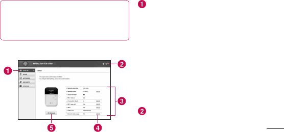
The Setting Page Screen
Top menu
Click a menu item to switch the setting
page. You can select the following items.
•STATUS
•WLAN
•NETWORK
•SECURITY
•SYSTEM
The submenu appears for some items,
and you can switch the setting screen.
[Logout]
Click to log out from the setting page.
50
Settings
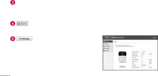
Setting screen
The setting items for the function
selected from the menu items appear.
Click to edit the setting.
Click to refresh the information on the
“Status” screen.
Confirming Connection/Setting
Conditions of this Terminal
1
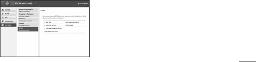
Click [STATUS] in the top menu.
“Status” screen appears.
•Click[Refresh]torefreshtheinformation.

51
Network selection*: The connecting band
is displayed.
Network name*: The connecting network
name is displayed.
Signal strength* : The current level of
radio wave reception is displayed.
Wi-Fi status: The status of the wireless
LAN function is displayed.
Connected clients: The number of
currently connected terminals via wireless
LAN is displayed.
Wi-Fi auto off: The setting status of the
Wi-Fi auto off function is displayed.
WPS: The operating status of the WPS
function is displayed.
USIM card: Phone number of Micro USIM
is displayed.
Network data usage*: The current amount
of data communication is displayed. Data
communication in overseas is not be added
to this amount.
* When the Micro USIM is not inserted, the items
do not appear.
On the “Status” screen, “USIM card has not
been inserted properly or is invalid” appears.
52
Settings
Setting Wireless LAN
NOTE: When using wireless LAN overseas,
check the available frequency band, laws,
regulations or other conditions of the country
beforehand.
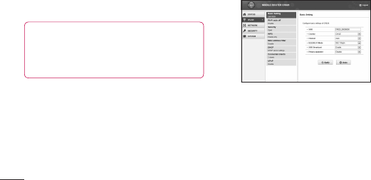
Setting Basic Functions of Wireless
LAN
1
In the top menu, click [WLAN].
2
In the submenu, click [Basic Setting].
3
On the setting screen, set the required
items.
SSID (Default: CR820_XXXXXXXX)
Set the network name (SSID) of the wireless
LAN. You can enter up to 32 letters with
one-byte alphanumeric, “-(hyphen)” and
“_(under bar)”.
Country (Default: CHILE)
Select a country name where this terminal is
used. (This field specifies the range of Wlan

53
channel.)
Channel (Default: Auto)
Select a channel of wireless LAN.
IEEE802.11 Mode: (Default: 802.11b/g/n)
Select an operation mode of wireless LAN.
- 802.11b/g/n
- 802.11b/g
- Only 802.11b
- Only 802.11g
- Only 802.11n
(When the security mode is set to “WEP”,
or when the mode is set to “WPA-PSK” or
“WPA2-PSK” and “TKIP” is selected, “Only
802.11n” or “802.11b/g/n” cannot be
selected.)
SSID Broadcast (Default: Enable)
Select whether to display SSID on the wireless
LAN terminal.
- Enable: SSID is displayed
- Disable: SSID is not displayed
Privacy separator (Default: Disable)
Select whether to prohibit communication
between wireless LAN terminals.
- Enable: Communication is prohibited
- Disable: Communication is not prohibited
4
Click [Apply] to save the setting.
54
Settings
Setting Wi-Fi auto off Function
1
In the top menu, click [WLAN].
2
In the submenu, click [Wi-Fi auto off].
3
On the setting screen, set the required
items.
Wi-Fi auto off (Default: Enable)
Select whether to set the wireless LAN
function to off automatically and power saving
mode when no client connection is made in a
certain period.
- Enable: The wireless LAN function is set
to off
- Disable: The wireless LAN function is not
set to off
• When Enable is set
Wi-Fi off time (min) (Default: 10)
When “Enable” is set to Wi-Fi auto off, select
the time (minutes) to set automatically to off.
55
- 10
- 30
- 60
4
Click [Apply] to save the setting.
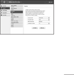
Setting Security Mode of Wireless
LAN
1
In the top menu, click [WLAN].
2
In the submenu, click [Security].
3
On the setting screen, set the required
items.
Security mode (Default: WPA/WPA2-PSK
mixed)
Select the security mode of wireless LAN.
- Open
- WEP
- WPA-PSK

56
Settings
- WPA2-PSK
- WPA/WPA2-PSK mixed
Depending on the Security mode setting, the
following setting items are different.
• When Open is set
Limitation of clients (Default: 1)
The number of terminals which can be
connected is displayed (it cannot be
changed.).
• When WEP is set
WEP key1-4 (Default: XXXXX)
Enter WEP key.
You can enter 5, 10, 13 or 26 letters with
one-byte alphanumeric.
For 5-letter or 13-letter key, use a key with
one-byte alphanumeric (0-9, a-z, A-Z).
For 10-letter or 26-letter key, use
hexadecimal numbers (0-9, A-F).
Only the specified number of WEP key in
“Current WEP key” is judged for letter type
to enter.
Current WEP key (Default: 1)
Select the number of WEP key to use. For
Wireless LAN terminal which cannot specify
the index of WEP key (iPod touch and IPad,
etc.), WEP key 2-4 cannot be used.
Limitation of clients (Default: 10)
The number of terminals which can be
connected is displayed.

57
• When WPA-PSK is set
Encryption type (Default: TKIP)
Select the encryption type.
- AES
- TKIP
WPA shared key (Default: XXXXXXXX)
Enter Security key of WPA.
You can enter 8-64 letters with one-byte
alphanumeric.
For 64-letter key, use hexadecimal numbers
(0-9, A-F).
Limitation of clients (Default: 10)
The number of terminals which can be
connected is displayed.
• When WPA2-PSK is set
Encryption type (Default: AES)
Select an encryption type.
- AES
- TKIP
WPA2 shared key (Default: XXXXXXXX)
Enter Security key of WPA2.
You can enter 8-64 letters with one-byte
alphanumeric.
For 64-letter key, use hexadecimal numbers
(0-9, A-F).
Limitation of clients (Default: 10)
The number of terminals which can be
connected is displayed.
58
Settings
• When WPA/WPA2-PSK mixed is set WPA/
WPA2 shared key (Default: P40)
Enter Security key of WPA/WPA2.
You can enter 8-64 letters with one-byte
alphanumeric. For 64-letter key, use
hexadecimal numbers (0-9, A-F).
Limitation of clients (Default: 10)
The number of terminals which can be
connected is displayed.
4
Click [Apply] to save the setting.
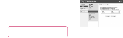
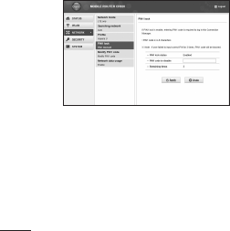
Setting WPS Function
NOTE: WPS Function cannot be used when
“WEP” is set for “Security”.
1
In the top menu, click [WLAN].
2
In the submenu, click [WPS].
3
On the setting screen, set the required
items.

59
WPS (Default: Enable)
Select whether to use WPS function.
- Enable: WPS function is used
- Disable: WPS function is not used
• When Enable is set
WPS type (Default: Push button)
Select a type of WPS function.
- Enable only: When connect with WPS
type after pressing the WPS button of this
terminal (WPS function is not activated if
you press [Apply] button.)
- Push button: When you use the WPS button
or connect with WPS type after clicking
[Apply] button
- WPS PIN: When you connect by entering the
PIN code (8-digit number) for WPS
WPS PIN
Enter the specified PIN code.
4
Click [Apply] to save the selected WPS
setting.
The saved WPS setting is valid even after
restarting of this terminal.
Setting MAC Address Filter
1
In the top menu, click [WLAN].
2
In the submenu, click [MAC address
filter].
3
On the setting screen, set the required
items.
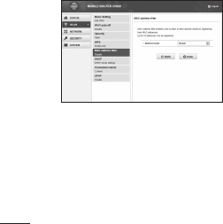
60
Settings
Restrict mode (Default: Disable)
Select an operation mode of MAC address
filter function.
- Disable: MAC address filter is not used
- Allow: Allows the connection only to this
terminal with the specified MAC address
- Deny: Prohibits the connection to this
terminal with the specified MAC address
• When Allow or Deny is set
Mac addresses entry field appears.
Enter the specified terminal's MAC address.
You can specify up to 10 MAC addresses.
4
Click [Apply] to save the setting.
Setting DHCP Function
1
In the top menu, click [WLAN].
2
In the submenu, click [DHCP].
3
On the setting screen, set the required
items.
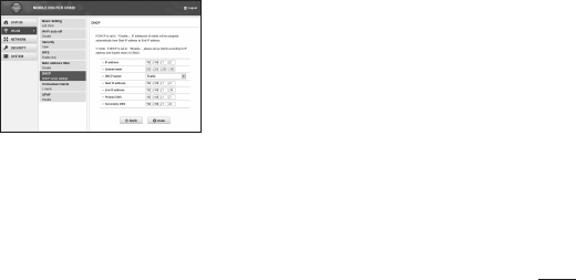
61
IP address (Default: 192.168.2.1)
Set private IP address of this terminal.
Subnet mask (Default: 255.255.255.0)
Set subnet mask of LAN.
DHCP server (Default: Enable)
Select whether to use DHCP function.
- Enable: DHCP function is used
- Disable: DHCP function is not used
• When Enable is set
Start IP address (Default: 192.168.2.2)
Set the minimum IP address assigned to this
terminal.
End IP address (Default: 192.168.2.99)
Set the maximum IP address assigned to this
terminal.
Primary DNS (Default: 192.168.2.1)
Set IP address of primary DNS server.
Secondary DNS (Default: 0.0.0.0)
Set IP address of secondary DNS server.
4
Click [Apply] to save the setting.
62
Settings
Confirming Connected Clients
1
In the top menu, click [WLAN].
2
In the submenu, click [Connected clients].
3
The connected terminal's information
appears.
•Click[Refresh]torefreshtheinformation.
4
To disconnect, click in the
“Disconnect” field.
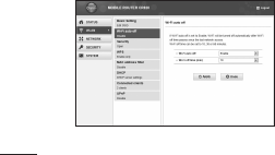
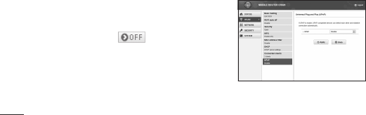
Setting UPnP Function
To use the application using the UPnP
function, set to “Enable” the UPnP function.
1
In the top menu, click [WLAN].
2
In the submenu, click [UPnP].
3
On the setting screen, set the required
items.
63
UPnP (Default: Disable)
Select whether to use the UPnP function.
- Enable: UPnP function is used
- Disable: UPnP function is not used
4
Click [Apply] to save the setting.
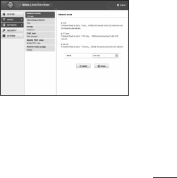
Setting Network
Setting Network mode Function
1
In the top menu, click [NETWORK].
2
In the submenu, click [Network mode].
3
On the setting screen, set the required
items.
Band (Default: Auto)
- Auto: Connect the LTE network or the 3G
network automatically.
- LTE only: Connect the LTE network only.
- 3G only: Connect the 3G network only.
64
Settings
4
Click [Apply] to save the setting.
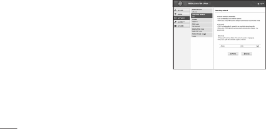
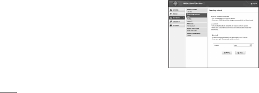
Selecting a network
You can specify the network.
1
In the top menu, click [NETWORK].
2
In the submenu, click [Searching
network].
3
On the setting screen, set the required
items. Mode (Default: Auto)
Select whether to specify the network.
- Auto: The network to connect is
automatically selected.
- Manual: Select when you specify the
network. Click [Apply] to search the available
network and register it to [Operators].
65
• When Manual is set
Operators (Default: none)
Select a network to connect.
4
Click [Apply] to save the setting.
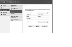
Registering the Access Point
Settings
Register, edit or delete the access point
settings. You can register up to 10 access
points.
•By default, the setting for Claro is
registered and you cannot delete it. When
using Claro, the following setting is not
necessary.
1
In the top menu, click [NETWORK].
2
In the submenu, click [Profile].
3
To register a new access point, click
[Add New].

66
Settings
• To edit an existing access point
In [Current profile], select an access point
to edit.
Follow Procedure 4.
Follow Procedure 6.
• To delete an existing access point
In [Current profile], select an access point
to delete.
Click [Delete].
Click [OK].
4
On the setting screen, set the required
items.
Profile name (Default: clarochile)
Enter an access point name. You can enter up
to 15 letters with one-byte alphanumeric.
APN (Default: bam.clarochile.cl)
Enter APN. You can enter up to 99 letters with
one-byte alphanumeric, “- (hyphen)”, “@ (at
mark)”, “. (period)” and “_ (under bar)”.
Username (Default: None)
Enter the user name specified by the provider.
You can enter up to 64 letters with one-byte
alphanumeric, “- (hyphen)”, “@ (at mark)”, “.
(period)” and “_ (under bar)”.
Password (Default: None)
Enter the password specified by the provider.
You can enter up to 32 letters with one-byte

67
alphanumeric, “- (hyphen)”, “@ (at mark)”, “.
(period)” and “_ (under bar)”.
Authentication (Default: CHAP)
Select the authentication method of the
access point.
- None
- PAP
- CHAP
5
To register a new access point, click
[Save].
6
Click [Apply] to save the setting.
Protecting the Terminal with the
Security Code
When this function is set, network
communication is locked and entering the
security code (PIN1 code) is required when
logging in to the setting page.
1
In the top menu, click [NETWORK].
2
In the submenu, click [PIN1 lock].
3
On the setting screen, set the required
items.
68
Settings
PIN1 lock status
The current setting condition is displayed.
- Enable: PIN1 lock is set
- Disable: PIN1 lock is canceled
• When Enable is set
PIN1 code to disable
Enter PIN1 code set to the Micro USIM card.
• When Disable is set
PIN1 code to enable
Enter PIN1 code set to the Micro USIM card.
4
Click [Apply].
5
When “Enabled” is set, hold down the
power button for over 2 seconds to turn
the power off, and then turn on again.

69
Unlocking PIN Lock
If you improperly enter the PIN1 code
for 3 times in a row, further entry is
locked automatically. In this case, enter
“Unblocking PIN Code” to unlock.
1
Enter the unblocking PIN code in [PUK
code] field.
2
Enter the new PIN1 code in the [New
PIN1 code] field.
3
In [Confirm PIN1 code] field, enter the
same PIN1 code as [New PIN1 code] for
confirmation.
4
Click [Apply].
Changing the Security Code
You can change the security code (PIN1
code).
•Changingsecuritycode(PIN1code)is
available only when PIN1 lock is set to
“Enabled”.
1
In the top menu, click [NETWORK].
2
In the submenu, click [Modify PIN1
code].
3
On the setting screen, set the required
items.
70
Settings
Current PIN1 code
Enter PIN1 code set to the Micro USIM card.
New PIN1 code
Enter the new PIN1 code.
Confirm PIN1 code
Enter the same code as [New PIN1 code] for
confirmation.
4
Click [Apply].
PIN1 code is changed.
Displaying Network data usage
The amount of data communication is
displayed. Data communication in overseas
is not be added to this amount. Also, the
amount of data communication in the
international roaming area is not displayed.
1
In the top menu, click [NETWORK].
2
In the submenu, click [Network data
usage].
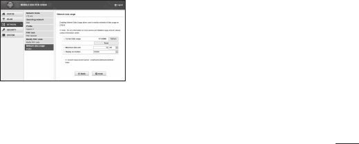
71
3
On the setting screen, set the required
items.
Current data usage
Click [Refresh] to see the latest information.
Click [Reset] to reset the information of usage.
The usage is automatically reset in the
following cases.
- When the Micro USIM is replaced
Maximum data size (Default: Disable)
Select from KB, MB and GB, and enter the
valid value*.
* Valid value: Positive integer from 1 to
1024
Not available: Negative number, 0, decimal
point and anything other than the valid
value
* Even if maximum data size is set, data
communication will not stop when data
usage is over the maximum data size. It is
only for your reference.
72
Settings
Display on modem (Default: Enable)
Enable: The amount of data communication is
displayed on the display of this terminal.
Disable: The amount of data communication is
not displayed on the display of this terminal.
4
Click [Apply] to save the setting.
Setting Security Functions
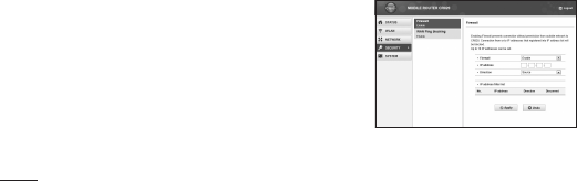
Using Firewall Function
Unauthorized access via the Internet can be
blocked by using the Firewall function. Also,
you can set IP filter.
1
In the top menu, click [SECURITY].
2
In the submenu, click [Firewall].
3
On the setting screen, set the required
items.

73
Firewall (Default: Disable)
Set whether to activate the Firewall function.
- Enable: Firewall function is activated. You
can set IP filter.
- Disable: Firewall function is deactivated.
• When Enable is set
You can set IP filter.
IP address
When registering IP filter, enter source or
destination IP address.
Direction (Default: Source)
Specify the direction of communication to
interrupt.
- Source: Interrupt the access from the
specified IP address.
- Destination: Interrupt the access to the
specified IP address.
IP address filter list
List of registered IP filter appears.
- : Delete registered IP filter.
4
Click [Apply].
Discarding WAN Ping
You can discard the Ping request to access
from WAN to prevent answering and
block the IP information leakage from this
terminal and LAN terminals.
74
Settings
1
In the top menu, click [SECURITY].
2
In the submenu, click [WAN Ping
blocking].
3
On the setting screen, set the required
items.
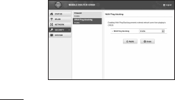
WAN Ping blocking (Default: Disable)
Set whether to activate the WAN Ping
blocking function.
- Enable: Activate the WAN Ping blocking
function.
- Disable: Deactivate the WAN Ping blocking
function.
4
Click [Apply].
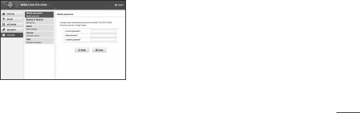
Managing the System
Changing Log-in Password
You can change the log-in password of the
setting page. You can enter only a 4-digit
number as a password.
75
1
In the top menu, click [SYSTEM].
2
In the submenu, click [Modify password].
3
On the setting screen, set the required
items.
Current password
Enter the current password.
New password
Enter the new password.
Confirm password
Enter the same password as [New password]
for confirmation.
4
Click [Apply].
The message “Password is changed
successfully” appears.
5
Click [OK].
76
Settings
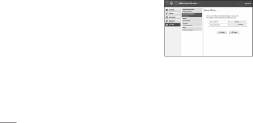
Saving/Restoring the Setting Data
All setting data can be saved to a PC on
which the setting page is opened. Also,
saved setting data can be restored in this
terminal.
1
In the top menu, click [SYSTEM].
2
In the submenu, click [Backup &
Restore].
3
In the setting screen, make the following
procedures.
Backup to file
Click [Backup], specify the file name (Default:
webcm_config.cfg) and save the current
setting.
* Depending on the browser, the file name
cannot be specified.
77
Restore from file
Click [Refer to...] and specify the file to
restore.
4
Click [Apply].
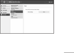
Resetting the Settings
You can reset all settings of the setting
page to default. However, the amount of
data communication which is displayed on
the display cannot be reset. For resetting
the amount of data communication, see
“Displaying Network data usage”.
•You can also reset the settings by
pressing the buttons on this terminal.
1
In the top menu, click [SYSTEM].
2
In the submenu, click [Reset].
3
Click [Reset].
4
Click [OK].
Log out from the setting page and the
communication is disconnected.

78
Settings
Confirming the Version Information
1
In the top menu, click [SYSTEM].
2
In the submenu, click [Version].
The version information of firmware and this
terminal appears.
3
Make setting for Software Update.
Automatically check new S/W (Default:
ON)
- ON: Check the update file automatically.
- OFF: Check the update file manually.
• When ON is set
The confirmation message for software
update appears each time you log in. To make
the message not to appear, set to “OFF”.
• When OFF is set
Click [Check now] to check if you have any
update files, and a message appears when a
new file exists.
For update procedure, see “Updating
Software”.
4
When you have changed software
update setting, click [Apply].
79
Displaying the Inquiries
1
In the top menu, click [SYSTEM].
2
In the submenu, click [Help].
The information of the inquiry website, phone
number and the URL of Instruction Manual
(PDF) appears.
80
Overseas Use
Setting the Searching Methods
for Available Networks and
Access Point
Set an available network (communication
operator) at your current location manually
(Manual setting is possible only for using
overseas). You can make settings related to
network by logging-in to the setting page.
1
Log in to the setting page.
For details, see “Logging-in to MOBILE
ROUTER CR820”.
2
Click [NETWORK] in the top menu.
3
Click [Searching network] in submenu,
and set each items.

81
Mode*
Select whether to specify the access point
network.
- Auto: Network that can be connected is
automatically selected.
- Manual: Select to specify the network. Click
[Apply] to search the available access point
and register it to [Operators].
4
Click [Apply] to save the setting
contents.
5
Click [Logout].
NOTE:
While using overseas
- Some communication services may not be
available depending on the overseas carrier
or network.

82
Troubleshooting
Power source and charging problems
Symptom Check
Power does
not turn on
Check if the battery pack is inserted
correctly.
Check if the battery pack is
exhausted.
Symptom Check
Cannot
charge
Check the following.
•Checkifthebatterypackis
inserted correctly.
•Checkiftheadapter'spowerplug
is inserted to the outlet correctly.
•CheckifACAdapterisconnected
to this terminal correctly.
•CheckifACAdapterconnectoris
connected to microUSB Connection
Cable correctly.
•CheckifthePCturnsonwhen
using microUSB Connection Cable.
Troubleshooting

83
Operation problems
Symptom Check
This terminal
becomes
hot while
operating or
charging
This terminal, battery pack or adapter
may become hot while operating or
charging. There is no problem about
safety. Continue to use it.
Symptom Check
The usage
time
provided by
the battery is
short
Check the following.
•Checkifthisterminalisleftforalongtime
under the state out of the service area.
•Whenitisoutofservicearea,more
powers is consumed to search available
radio waves.
•Theusagetimeprovidedbythebattery
pack varies by the operation environment
and battery pack's deterioration.
•Thebatterypackisaconsumablepart.
Each time it is charged, the usage time
with each charging reduces. Even in the full
charge state, when the usage time is too
short, purchase a new battery pack of the
specified type.

84
Troubleshooting
Symptom Check
The power
turns off
or restarts
automatically
If the jack of battery pack is dirty, the
contact may become poor and the
power may shut off. If it is dirty, clean
with a dry cloth or cotton swab.
The Micro
USIM is not
recognized
Check if the Micro USIM is inserted in
the correct direction.
This terminal is not recognized
Symptom Check
This terminal
is not
recognized
by the PC
connected
with
microUSB
Connection
Cable
Check if this terminal is correctly
connected to the PC with microUSB
Connection Cable.
Remove microUSB Connection Cable
from the PC, restart the PC and
reconnect.
85
Symptom Check
This terminal
is not
recognized
by the PC
connected
with
microUSB
Connection
Cable
Uninstall CR820 driver and reconnect.
To uninstall the driver
• For Windows 7
Click (Start) “Control
panel” “Program”
“Program and function”.
- “Uninstall or modify program”
window appears.
Select “LG Router Driver” and
click “Uninstall”.
Click “OK”.
Click “OK”.
Symptom Check
This terminal
is not
recognized
by the PC
connected
with
microUSB
Connection
Cable
• For Windows Vista
Click (Start) “Settings”
“Control panel” “Program”
“Program and function”.
- “Uninstall or modify program”
window appears.
Select “LG Router Driver” and
click “Uninstall”.
Click “Continue”.
Click “OK”.
Click “OK”.
86
Troubleshooting
Symptom Check
This terminal
is not
recognized
by the PC
connected
with
microUSB
Connection
Cable
• For Windows XP
Click “Start” “Control panel”
“Add or delete program”.
- “Add or delete program”
window appears.
Select “LG Router Driver” and
click “Delete”.
Click “OK”.
Confirm that “W-TCP (Cancel
optimization of W-TCP function
(Recommended))” has selected,
and click “Complete”.
Problems with wireless LAN
Symptom Check
Cannot
connect the
wireless LAN
terminal
Check if the wireless LAN functions
of this terminal and the wireless LAN
terminal are turned on.
Check if the correct Security key is
set to the wireless LAN terminal.
If you forget the Security key set to
this terminal, see “Setting Security
Mode of Wireless LAN (Security)”
to reset Security key and make
connecting operation again.
87
Symptom Check
Cannot
connect the
wireless LAN
terminal
If the security mode other than WEP2-PSK
is set to this terminal, you need to make the
same settings for the target wireless LAN
terminal. For details, refer to the instruction
manual of your wireless LAN terminal.
• Example: Security mode is WEP
For Windows 7
Click (Start) “Control panel)”
“Network and Internet” “Network and Sharing
Center” “Manage Wireless Networks”
Right click the name of this terminal and
“Properties” “Security” tab Set following:
- Security Type: no authentication
- Encryption Type: WEP
- Network Security Key: WEP key of this terminal
whose number is selected in Key index
Symptom Check
Cannot
connect the
wireless LAN
terminal
• Example: Security mode is WEP
For Mac OS 10.7
[Apple] menu [System
Preferences...] [ [Network]
Select [Wi-Fi] on the left screen
[Edit network] on [Network] [ + ]
Enter any name in [Untitled] [OK]
Check [Display Wi-Fi status on menu
bar] [Details] Select [Wi-Fi] on
tab located in the upper of screen
[ + ] Enter network name Select
[WEP] in [Security] Enter WEP key
1 of this terminal in [Password]
[OK] [OK] Check [Wi-Fi ON] if
the status is [OFF], and [Apply]

88
Troubleshooting
Symptom Check
Cannot
connect the
wireless LAN
terminal
If the connection cannot be made
with the WPS function, refer to the
instruction manual of your wireless
LAN terminal, check the setting of
the WPS function, and then make
connecting operation again.
When connecting the wireless LAN
terminal to which PIN code from WPS
is specified, check if “WPS PIN” is
selected in WPS function settings
of this terminal and the correct PIN
code is set.
Communication problems
Symptom Check
Communications
are not possible
Check if signals are received in the
service area.
If a security code is set to the Micro
USIM, log in to the setting page and
enter PIN1 code.
Check the settings of this terminal
and the APN registration.
Depending on the radio wave
condition, the Internet connection
may not be available. In that case,
turn this terminal off and turn it
on again.

89
Symptom Check
Communications
are not possible
When connecting to the Internet
with this terminal, check that
other communication devices are
disconnected.
Internet connection is unavailable
when an icon shows not connected
appears on the display of this
terminal.
- Hold down the Wi-Fi button for more
than 2 seconds to turn on the Wi-Fi
function.
- Top menu of MOBILE ROUTER CR820
Click “ NETWORK” “Profile”, confirm
that the settings are correct.
Overseas use problems
Symptom Check
Cannot perform
communication
overseas
(when “out of
service area” is
displayed)
Change the network settings or the
setting of overseas communication
operator.
- Set “Searching network” to
“Manual”.
- Confirm “Profile” settings.
It may recover by turning this
terminal's power off and on.

90
Troubleshooting
Symptom Check
Communication
becomes
unavailable
suddenly while
using overseas
Check if the usage charge has exceeded
the limit.
If the charge has exceeded the limit, pay
the cumulative price.
Other problems
Symptom Check
This terminal
stopped
working
suddenly
Check that the Micro USIM is properly
inserted to this terminal.
Symptom Check
Internet
connection
speed
decreased
suddenly
Speed may be decreased in unsteady
areas such as
LTE/W-CDMA/HSDPA/HSUPA service
environment. Move it to another place
and connect again.
To perform communication with
WindowsXP,theoptimizationofPC
communication setting is necessary.
Connect this terminal and a PC with
USB Extension Cable and install the
driver. Confirm that “W-TCP (Use
W-TCP function (Recommended))”
is selected.
Back Cover
is deviated
Fit Back Cover to this terminal, and
press each tab to close it firmly.

91
Error Messages
The following messages may appear when
using the setting page (MOBILE ROUTER
CR820).
Error Messages Description
The password
you entered is
not correct.
An incorrect password is entered
for log-in. Click [OK] and enter
the correct password.
The PIN1 code
you entered is
not correct.
An incorrect PIN1 code is
entered. Click [OK] and enter the
correct PIN1 code.
Error Messages Description
PIN1 code is
blocked.
PIN1 code is locked because
PIN1 code has been improperly
entered 3 times in a row. Click
[OK], enter unblocking PIN code
in [PUK code] and new PIN1 code
in [New PIN1 code] and [Confirm
PIN1 code]. Click [Apply].
The PUK code
you entered is
not correct.
An incorrect unblocking PIN1
code is entered. Click [OK] and
enter the correct unblocking
PIN code.

92
Troubleshooting
Error Messages Description
PUK code is
blocked. Your
Micro USIM card
is not valid any
more.
Micro USIM is locked because
unblocking PIN1 code has been
improperly entered 10 times in
a row. Please contact service
center.
Warranty and After-Sales
Service
Warranty
•A written warranty is provided with every
terminal. Make sure that you receive it.
Store the warranty in a safe place after
you read it and verified that it contains
the “Shop name/date” you purchased
the product. If the written warranty does
not contain the necessary information,
contact the shop where you purchased
the product. The warranty is valid for
a period of one year from the date of
purchase.
•This product and all accessories are
subject to change, in part or whole, for
the sake of improvement without prior
notice.
93
Resetting this Terminal
To reset the terminal to the default settings,
make the following procedures. However,
the displayed Network data usage will not
be reset. For the details about resetting
Network data usage, see "Displaying
Network data usage".
1
Press both the WPS button and Wi-Fi
button at the same time for approximate
15 seconds.
“RESET” appears on this terminal's screen,
and the terminal is reset.

94
Troubleshooting
Main Specifications
Terminal
Model name CR820
Dimensions
(H×W×D)
Approx. 90mm×
Approx. 62mm×
Approx. 12.6 (thick
part: 12.9) mm
Weight Approx. 83.5g
(with battery pack
installed)
Continuous
communication
time
LTE Approx. 4 hours
3G (HSDPA/
HSUPA,
W-CDMA)
Approx. 5 hours
Display LTE Approx. 160 hours
3G (HSDPA/
HSUPA,
W-CDMA)
Approx. 320 hours
Charging time AC Adapter: Approx.
200minutes
USB: Approx.
270minutes

95
Display Type Organic EL
Size Approx. 1.2 inches
Pixels 128 dots (Horizontal)
× 96 dots (Vertical)
Communication method WAN: LTE/HSDPA/
HSUPA/W-CDMA
Wireless LAN:
IEEE802.11b/g/n
Communication speed Packet
communication:
Up to 100Mbps for
receiving data
Up to 50Mbps for
sending data
Battery pack
Model name Battery Pack
Battery type Lithiumion battery
Nominal voltage 3.8V
Nominal capacity 1,700mAh

96
Guidelines for safe and efficient use
Body-worn Operation
This Mobile Broadband USB Modem, model
CR820, is approved for use in normal size
laptop computers only (typically with 12” or
larger display screens).
To comply with FCC RF exposure
requirements, this modem should not be
used in configurations that cannot maintain
at least 0.5cm (approximately 0.2inches)
from your body.
Also, when using the USB extension cable,
place the USB modem away from your
body or any other transmitter of the laptop
or PC.
This USB modem has been tested for
compliance with FCC/IC RF exposure limits
in the laptop computers configurations with
horizontal and vertical USB slots and can be
used in laptop computers with substantially
similar physical dimensions, construction
and electrical and RF characteristics.
This device was tested for typical
body-worn operations with the back
of the phone kept 0.39 inches (1cm)
between the user's body and the back
of the phone. To comply with FCC RF
exposure requirements, a minimum
separation distance of 0.39 inches
(1cm) must be maintained between
the user's body and the back of the
phone.
Third-party belt-clips, holsters, and
similar accessories containing metallic
components may not be used. Body-
worn accessories that cannot maintain
0.39 inches (1cm) separation distance
between the user's body and the back
of the phone, and have not been tested
for typical
body-worn operations may not comply
with FCC RF exposure limits and should
be avoided.

97
When using this USB modem in your
computer, it must not be co-located or
simultaneously transmit with any other
radio (forexample, Bluetooth or WiFi radios)
in the computer.
Part 15.21 statement
Change or modifications that are not
expressly approved by the manufacturer
could void the user’s authority to operate
the equipment.
FCC Part 15 Class B
Compliance
This device and its accessories comply with
part15 of FCC rules.
Operation is subject to the following two
conditions:
(1) This device and its accessories may not
cause harmful interference.
(2) This device and its accessories must
accept any interference received,
including interference that causes
undesired operation.

98
Guidelines for safe and efficient use
Part 15.105 statement
This equipment has been tested and
found to comply with the limits for a class
B digital device, pursuant to Part 15 of
the FCC rules. These limits are designed
to provide reasonable protection against
harmful interference in a residential
installation. This equipment generates,
uses, and can radiate radio frequency
energy and, if not installed and used in
accordance with the instructions, may
cause harmful interference to radio
communications. However, there is no
guarantee that interference will not occur in
a particular installation.
If you experience interference with
reception (e.g., television), determine if
this equipment is causing the harmful
interference by turning the equipment off
and then back on to see if the interference
is affected. If necessary, try correcting the
interference by one or more of the following
measures:
- Reorient or relocate the receiving
antenna.

99
- Increase the separation between the
equipment and receiver.
- Connect the equipment into an outlet on
a circuit different from that to which the
receiver is connected.
- Consult the dealer or an experienced
radio/TV technician for help.
Consumer Information on SAR
(Specific Absorption Rate)
This device meets the government's
requirements for exposure to radio
waves. Your wireless device is a radio
transmitter and receiver. It is designed and
manufactured not to exceed the emission
limits for exposure to Radio Frequency (RF)
energy set by the Federal Communications
Commission of the U.S. Government.
These limits are part of comprehensive
guidelines and establish permitted levels
of RF energy for the general population.
The guidelines are based on standards that
were developed by independent scientific
organizations through periodic and
thorough evaluation of scientific studies.

100
Guidelines for safe and efficient use
The standards include a substantial safety
margin designed to assure the safety of all
persons, regardless of age and health.
The exposure standard for wireless devices
employs a unit of measurement known as
the Specific Absorption Rate, or SAR. The
SAR limit set by the FCC is 1.6 W/kg. Tests
for SAR are conducted using standard
operating positions specified by the FCC
with the device transmitting at its highest
certified power level in all tested frequency
bands. Although SAR is determined at the
highest certified power level, the actual
SAR level of the device while operating
can be well below the maximum value.
Because the device is designed to operate
at multiple power levels to use only the
power required to reach the network, in
general, the closer you are to a wireless
base station antenna, the lower the power
output.
Before a device is available for sale to the
public, it must be tested and certified to
the FCC that it does not exceed the limit
established by the government-adopted
requirement for safe exposure. The tests

101
are performed in positions and locations
(e.g., at the ear and worn on the body) as
required by the FCC for each model.
The FCC has granted an Equipment
Authorization for this device with all
reported SAR levels evaluated as in
compliance with the FCC RF emission
guidelines. SAR information on this device
is on file with the FCC and can be found
under the Display Grant section of http://
www.fcc.gov/oet/fccid after searching on
FCC ID ZNFCR820. Additional information
on Specific Absorption Rates (SAR) can be
found on the Cellular Telecommunications
Industry Association (CTIA) website at
http://www.ctia.org/.