LG Electronics USA DT-CG Personal Computer User Manual DT final EN 2
LG Electronics USA Personal Computer DT final EN 2
Contents
- 1. Users Manual Part 1
- 2. Users Manual Part 2
Users Manual Part 1


Thank you for using the LG product.
LG has manufactured and tested this product to provide you with a reliable computing
environment.
Please read this manual carefully before using the computer.
This sign calls attention to features and operations that may be dan-
gerous to the user. Follow the instruction closely to reduce the risk of
bodily harm or damage to the equipment.
Danger :Not following the instruction will result in immediate death or serious
injury.
Warning:Not following the instruction could result in death or serious injury.
Caution:Not following the instruction could result in minor or moderate injury
and/or damage to the product.
Microsoft, MS, MS-DOS, and Windows are trademarks of Microsoft Corporation in the
United States and/or other countries.
is a trademark of LG.
Copyright 2004 LG Electronics, Inc., DigitalMate Co., Ltd.
Information in this manual may include technical inaccuracies or typographical errors.
Images in this manual are for illustrative purposes only and may be different from the
actual product.
LG reserves the rights to make improvements and/or changes to the product without
notice.
Reproducing any or all of the information contained in this publication without written
permission is prohibited.
MultiNet computer complies with the radio frequency and safety standards of any
country or region in which it has been approved for wireless use.

3Contents
Contents
Contents .................................................................................................................. 3
1. Components............................................................................................................. 4
2. Installing the computer ............................................................................................. 8
3. Attaching external devices (customer purchased devices) .................................... 10
1. Basics
1. Starting the system setup....................................................................................... 12
2. Booting with a bootable floppy disk........................................................................ 14
3. Setting a password................................................................................................. 15
4. Changing or removing the password ..................................................................... 16
5. Recovering the factory default settings .................................................................. 18
6. Power management setup ..................................................................................... 19
2. System Setup
1. Opening the computer case ................................................................................... 20
2. Main board ............................................................................................................. 21
3. Connectors............................................................................................................. 22
4. Replacing the CPU................................................................................................. 24
5. Increasing memory................................................................................................. 28
6. Adding a hard disk drive......................................................................................... 32
7. Installing expansion cards...................................................................................... 39
3. System Expansion
1. Basics
4
1-1. Components
FG CG
DG/CM EG
Basics
ⓞ
ⓞ
ⓟ
ⓟ
ⓡⓡ
ⓠ
ⓡ
ⓠ
ⓟ
ⓣ
ⓢ
ⓢⓣⓢⓣ
ⓞ
ⓞ
ⓟ
ⓡ
ⓠ
ⓢ
ⓤ
ⓣ
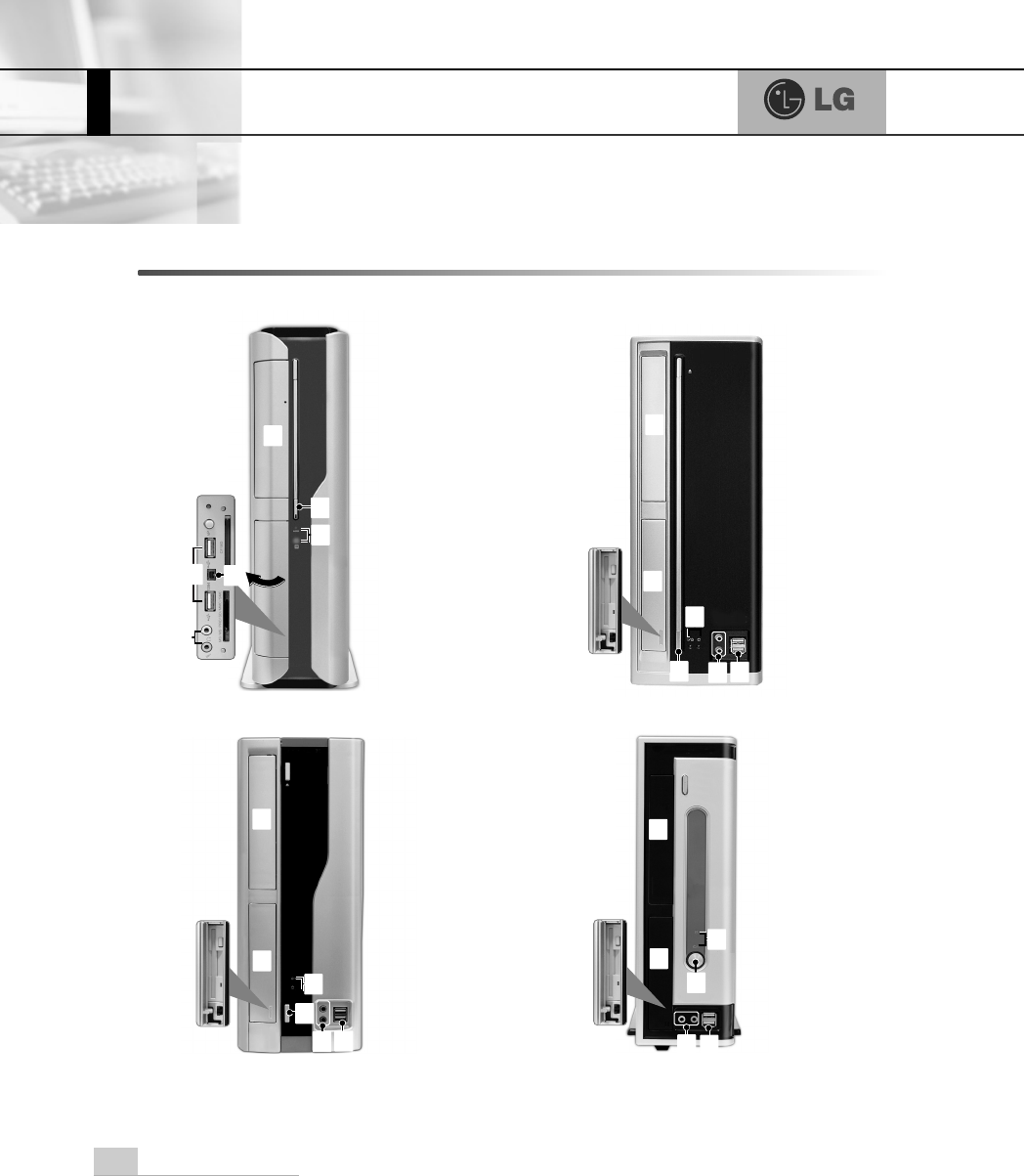
Front view

5Basics
ⓞPower button turns the power on/off the computer.
ⓟPower/ Hard disk drive status indicator indicates whether the computer is on
and the hard disk drive is in use(blinking indicates the hard disk drive is in use).
Note: Depending on the hard disk drive, the indicator may not blink and simply
goes off during multiple operations.
ⓠFloppy disk drive enables reading from and writing to a 3.5 inch floppy disk.
ⓡCD-ROM drive enables reading a data, video, or audio CD.
(Your computer may have a CD-RW or DVD-ROM drive depending on the model)
ⓢAudio jacks
Headphone jack connects to headphones.
Microphone jack connects to a microphone.
ⓣUSB connectors connects to a USB device or HUB. For example, you can con-
nect to a USB mouse, digital camera, or external hard disk drive.
Note: Your computer supports USB 2.0.
ⓤIEEE 1394 4 pin connector connects to IEEE 1394 4 pin devices such as digital
camcorder.
Note: Your computer may have different features and configuration from the comput-
ers shown above.
6 Basics
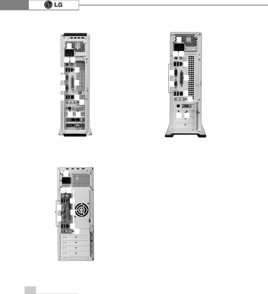
Rear view
CG/DG/CM
EG
FG
Note: Your computer may have different
features and configuration from the
computers shown above.
ⓞ
ⓞ
ⓞ
ⓟⓠ
ⓟⓠ
ⓣ
ⓤ
ⓟⓠ
ⓡ
ⓢ
ⓡ
ⓡⓢ
ⓥ
ⓥ
ⓦ
ⓢ
ⓣ
ⓤ
ⓧ
ⓧ
ⓨ ⓩ
ⓨ ⓩ
ⓣ
ⓤ
ⓡ
ⓥ
ⓦ
ⓦ
ⓧ

7Basics
ⓞPower jack connects to the power cord for supplying power to your computer.
ⓟKey board connector connects to a PS/2 keyboard.
ⓠMouse connector connects to a PS/2 mouse.
ⓡUSB connectors connect to USB devices or hubs. For example, you can connect
to a USB mouse, digital camera, or external hard disk drive.
Note: Your computer supports USB 2.0.
ⓢParallel connector connects to a parallel device such as printer or scanner.
ⓣSerial connector connects to a serial device.
ⓤVideo connector connects to a monitor.
ⓥAudio jacks
Microphone jack connects to a microphone.
Line-in connects to an external audio device.
Speaker jack connects to an external speaker.
ⓦLAN enables network connection between HUB and UTP (wire connection).
ⓧIEEE 1394 6 pin connector connects to IEEE 1394 6 pin devices, such as
exter-nal hard disk or CD-RW drive.
ⓨTV-Out connector connects to external devices such as Television.
ⓩVideo connector connects to a monitor cable.
Never disassemble the power supply.
There is the risk of fire, electric shock, and/or injuries.
8 Basics
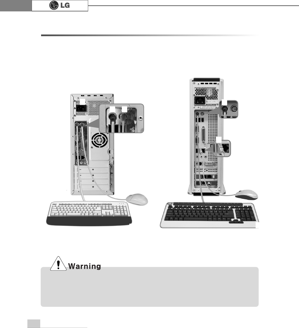
1-2. Installing the computer
Installing your computer may be easier than you think. Before the installation, be sure to
turn off the computer and other peripheral devices. The mouse and keyboard connec-
tors look identical; therefore, check the icons above the connectors before attaching the
mouse and keyboard. Your computer may be installed with different expansion cards
from the picture below.
CG/DG/CM/EG FG
Do not place a glass or container with water, chemicals, or liquid of any kind in it
on the computer.
There is the risk of electric shock and/or damage to the computer.
ⓞ ⓟ
ⓞ
ⓟ
ⓠ
ⓡⓡ
9Basics
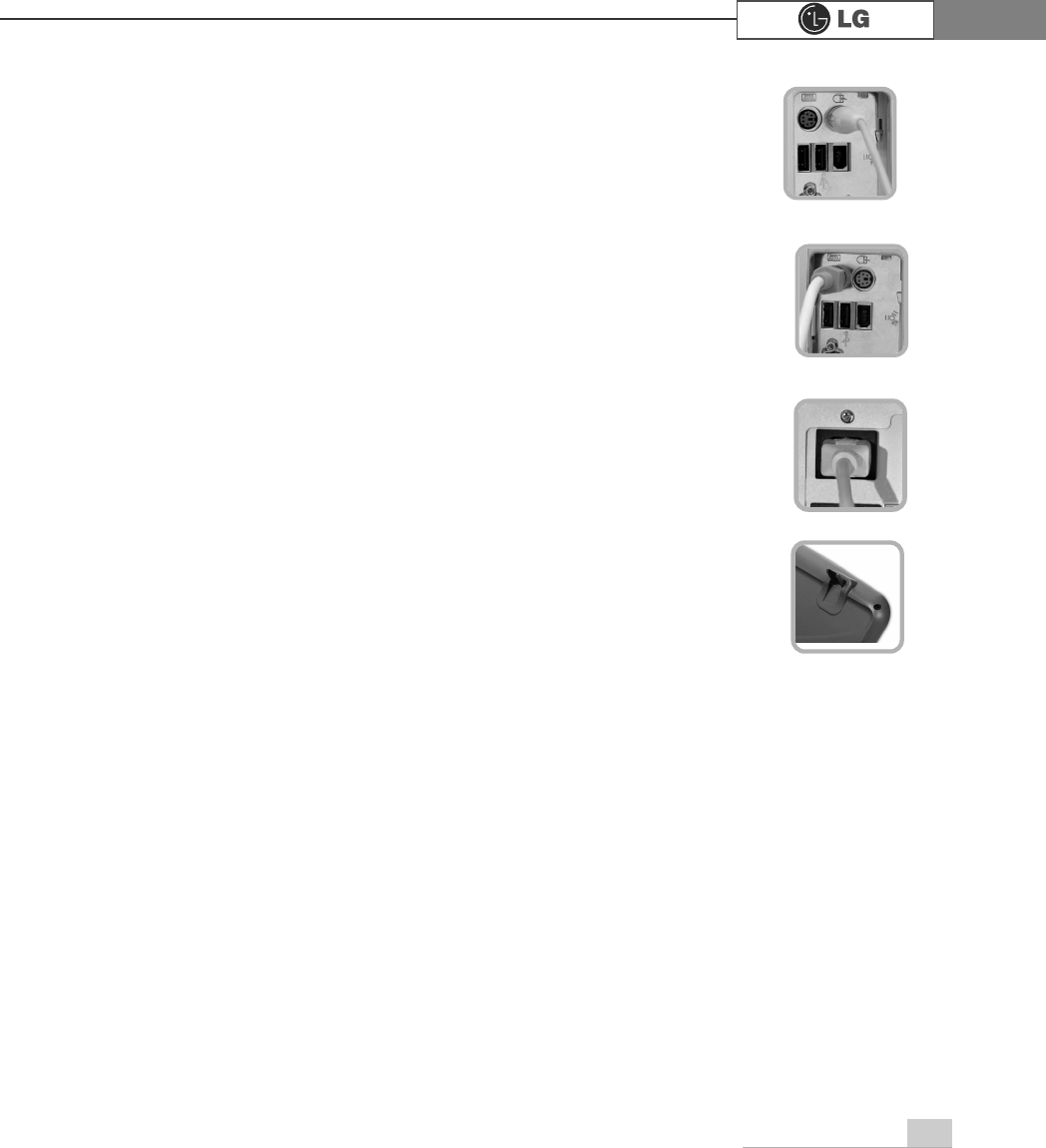
ⓞConnecting a mouse: The rectangular connector on the mouse
cable fits into one of the USB connectors on the front and real of the
computer.The round connector on the mouse cable fits into the PS/2
connector on the real of the computer. Be sure to align the 6 pins on
the cable with the corresponding holes on the connector.
ⓟConnecting a keyboard: The keyboard cable has a round connec-
tor with 6 pins. and the keyboard connector on the real of the com-
puter has 6 holes. Align the pins and holes, and attach the keyboard
cable to the computer as shown in the picture.
ⓠConnecting to power: Attach the power cord to the computer and
then plug the power cord into a wall socket.
ⓡKeyboard stand: The keyboard stand is located at the bottom of the
keyboard. Lift the stand to use the keyboard more comfortably.
10 Basics
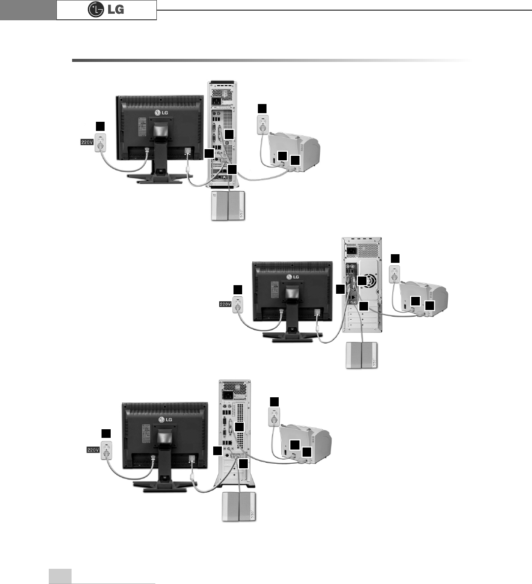
1-3. Attaching external devices(customer purchased devices)
FG
EG
1
7
7
7
23
4
6
5
4
5
4
5
6
3
1
1
2
2
6
3
CG/DG/CM

11Basics
Attaching a monitor(customer purchased device): The monitor cable and power cord
are included with the monitor. For using the monitor, refer to the user manual that
comes with the monitor.
‹´Connecting the monitor cable to the video card. The monitor cable sends signal from
the computer to monitor.
‹ˆConnecting the power cable to the monitor and plug it into an electrical outlet. The
power cord supplies power from the electrical outlet to monitor. You must turn on and
off the monitor with the power button on the monitor. If you want your computer to
supply power to the monitor, check the power specification of the monitor before attach-
ing the power cord to the computer.
Attaching a printer(customer purchased device): The printer cable and power cord are
included with the printer. For using the printer, refer to the user manual that comes with
the printer.
‹˜Attach the printer cable to the parallel connector on the computer.
‹¯Attach the printer cable to the parallel connector on the printer.
‹˘, ‹˙Attach the power cord to the printer and plug it into an electrical outlet.
Attaching a speaker(customer purchased device): Your computer does not have built-in
speakers. You must attach an external speaker to output sound.
ܬAttach a speaker cable to the speaker jack on the real of the computer.
Do not overload an electrical outlet with connections to multiple devices.
Overloading an electrical outlet may result in fire or electric shock.
Do not place the computer or other devices on the cables as they may be dam-
aged.
Do not touch the power cord or plug with wet hands. Doing so may result in elec-
tric shock.
2. System setup
12 System setup
The system setup saves your computer’s hardware configurations in CMOS RAM.
The system setup provides you with information, such as the size and type of your
hard disk, size of the installed memory, date, and time.
2-1. Starting the system setup
You may want to use the CMOS Setup Utility in the following situations:
Booting the system using a startup floppy disk. (Page 14)
Setting a password. (Page 15)
Changing or removing the password. (Page 16)
Recovering the factory default settings. (Page 18)
Keys used in the CMOS Setup Utility
Enter : Select the current item.
Esc : Close the current window or move to the previous window.
Cursor Control Keys: Move up, down, left, and right.
+, - : Increase or decrease the value.
Page Up : Increase or decrease the value.
Page Down : Increase or decrease the value.
F10 : Save or exit the system setup.
Do not change the system setup arbitrarily. Incorrect system setup may result in
errors while using the computer.
The menu and default factory settings of the CMOS Setup Utility may look differ-
ent from this manual. They may have been changed to improve the performance
of the system.
13System setup
Note
Cursor control keys (arrow keys) move the cursor up, down, to the left and right. If
Num Lock button is off, the arrow keys in the numeric keypad can be used just like
the cursor control keys.
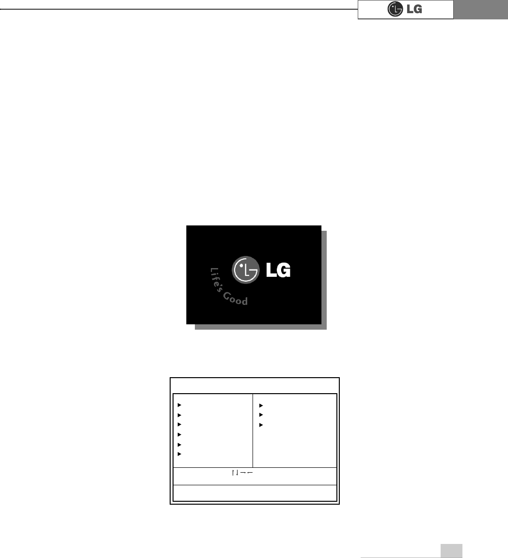
1. Turn on the computer and monitor
2. When LG logo appears on the screen, press Delete.
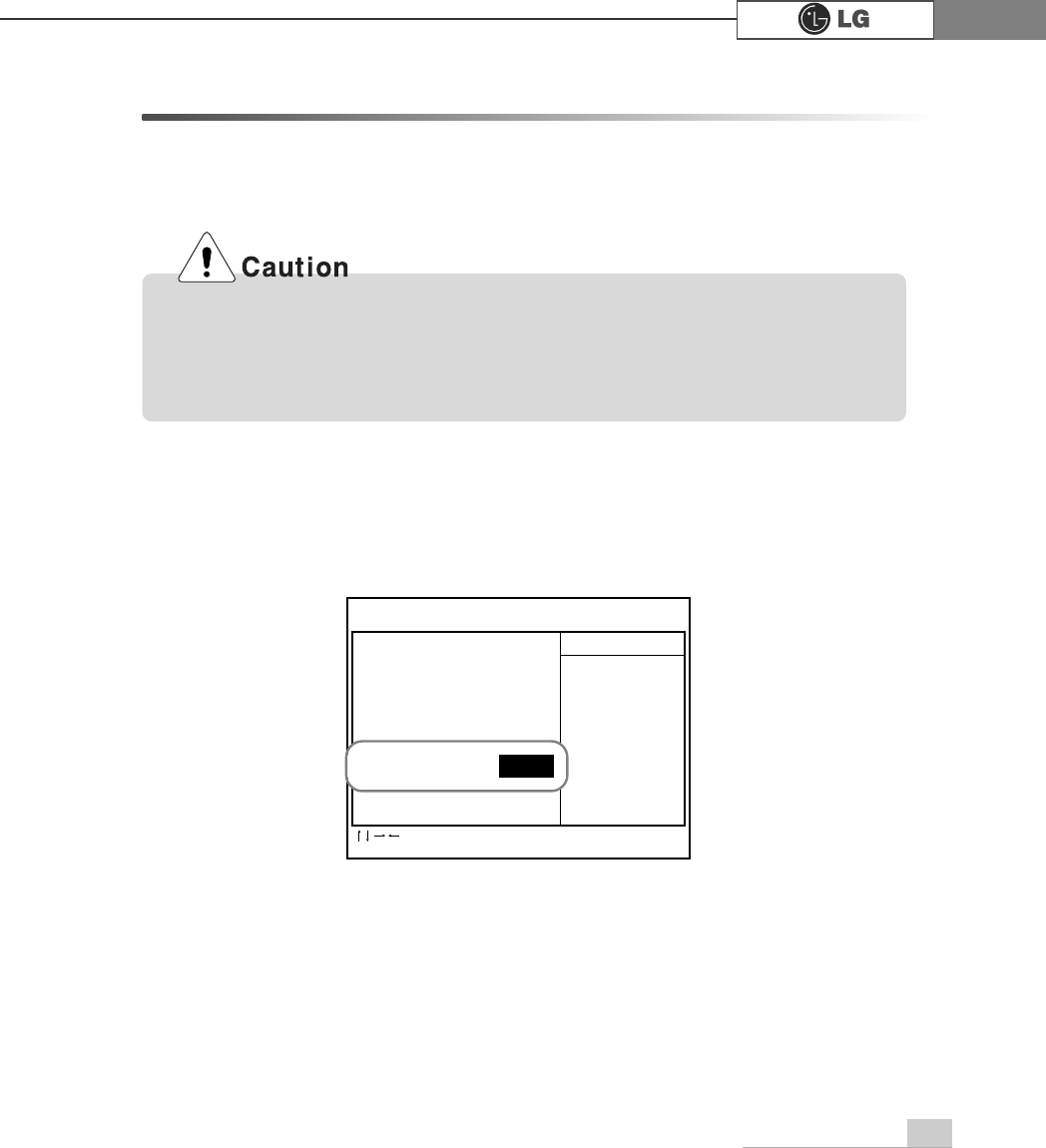
3. The CMOS Setup Utility window appears.
Standard CMOS Features
Advanced BIOS Features
Advanced Chipset Features
Integrated Peripherals
Power Management Setup
PnP/PCI Configurations
ESC:Quit
F10:Save & Exit Setup
:Select Item
CMOS Setup Utility-Copyright(C) 1984-2001 Award Software
PC Health Status
Frequency/Voltage Control
Load Optimized Defaults
Set Password
Save & Exit Setup
Exit Without Saving
Time, Date, Hard Disk Type...
Press DEL to enter SETUP
14 System setup
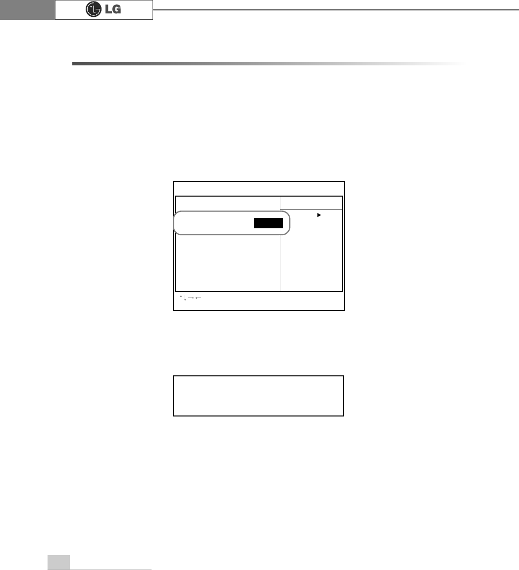
2-2. Booting with a bootable floppy disk
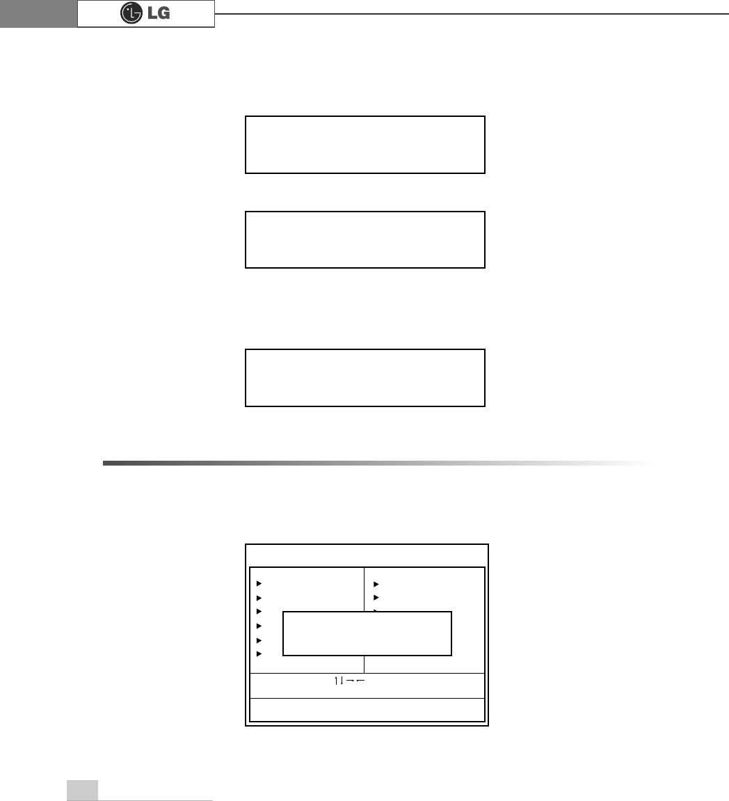
Follow the instruction below to set the floppy disk drive in the boot order.
1. Open the CMOS Setup Utility. Use the arrow keys to select Advanced BIOS
Features and press Enter.
2. Use the arrow keys to select 1st Boot Device, and Page Up and Page Down keys
to select Floppy.
3. Press F10 to save the new setting.
4. When the following message appears, press Enter. The computer restarts.
CMOS Setup Utility-Copyright(C) 1984-2001 Award Software
Advanced BIOS Features
Virus Warning Disabled Item Help
CPU L1&L2 Cache Enabled
1st Boot Device Floppy Menu Level
2nd Boot Device CD-ROM
3rd Boot Device HDD-0 Select Your Boot
Boot Other Device Enabled Device Priority
Swap Floppy Disabled
Seek Floppy Enabled
Boot Up Num-Lock LED On
Security Option System
APIC Mode Enabled
MPS Version Control For OS 1.4
Boot OS/2 for DRAM > 64MB No
Full Screen LOGO Show Disabled
Summary Screen Show Enabled
:Move Enter:Select +/-/PU/PD:Value F10:Save ESC:Exit
F1:Help F5:Previous Values F7:Optimized Defaults
SAVE to CMOS and EXIT(Y/N)? Y
Floppy1st Boot Device
15System setup
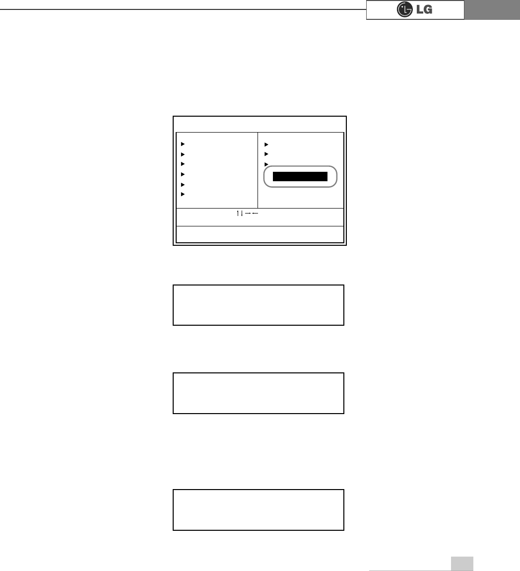
1. Start the CMOS Setup Utility. Use the arrow keys to select Advanced BIOS
Features, and then press Enter.
2. Use the arrow keys to select Security Option. Use the Page Up and Page Down
keys to select Setup or System, and then press Esc.
3. Use the arrow keys to select Set Password, and then press Enter.
Note
If you select Setup in the Security Option, the computer asks for a password next time
you try to enter the CMOS Setup Utility. If you select System, the computer asks for a
password next time you start the computer and also when you try to enter the CMOS
Setup Utility. Setting the System password prevents unauthorized users from using
the computer or changing the system setup.
2-3. Setting a password
If you want to protect the system setup from unauthorized users, follow the instruction
below to set a password.
You can set a password in the CMOS Setup Utility program.
CMOS Setup Utility-Copyright(C) 1984-2001 Award Software
Advanced BIOS Features
Quick Boot Enabled Item Help
Anti-Virus Protection Disabled
CPU L1&L2 Cache Enabled Menu Level
Fast Boot Enabled
1st Boot Device CD-ROM Select whether
2nd Boot Device Floppy Password is required
3rd Boot Device HDD-0 every time the system
Boot Other Device Enabled boots or only when
Swap Floppy Disabled you enter setup
Seek Floppy Disabled
MPS Table Version 1.4
Boot OS/2 for DRAM > 64MB No
Hard Disk S.M.A.R.T Disabled
Full Screen LOGO Show Enabled
Summary Screen Show Disabled
:Move Enter:Select +/-/PU/PD:Value F10:Save ESC:Exit
F1:Help F5:Previous Values F7:Optimized Defaults
SetupSecurity Option
If you forget the password, you cannot gain access to your system. Be sure to
write down the password in a safe place only you can refer to in case you forget
the password.
16 System setup
2-4. Changing or removing the password
You must know the password to change or remove it.
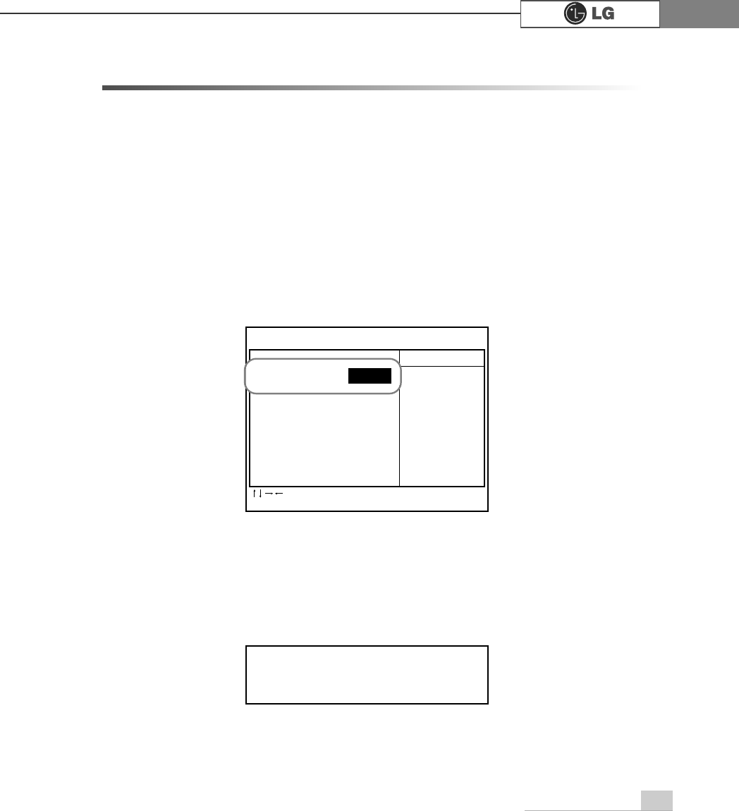
1. Start the CMOS Setup Utility, enter your password, and then press Enter.
5. If the following message appears, enter the password again, and then press Enter.
6. Press F10 to save the new settings.
7. If the following message appears, press Enter. The computer restarts.
4. If the following message appears, enter the new password and then press Enter. A
password must consist of characters A~Z and numbers 0~9, and has the maxi-
mum length of 8.
Enter Password:
Confirm Password:
SAVE to CMOS and EXIT(Y/N)? Y
Standard CMOS Features
Advanced BIOS Features
Advanced Chipset Features
Integrated Peripherals
Power Management Setup
PnP/PCI Configurations
ESC:Quit
F10:Save & Exit Setup
:Select Item
CMOS Setup Utility-Copyright(C) 1984-2001 Award Software
PC Health Status
Frequency/Voltage Control
Load Optimized Defaults
Set Password
Save & Exit Setup
Exit Without Saving
Change/Set/Disable Password
Enter Password:
17System setup
To change the password, follow the instructions on Setting a password.
To remove the password, follow the instructions below.
2. Use arrow keys to select Set Password, and then press Enter.
3. If the following message appears, press Enter.
4. If the following message appears, press Enter.
5. Press F10 to save the new setting.
6. If the following message appears, press Y key and Enter. The computer restarts.
Enter Password:
PASSWORD DISABLED!!!
Press any key to continue...
SAVE to CMOS and EXIT(Y/N)? Y
Standard CMOS Features
Advanced BIOS Features
Advanced Chipset Features
Integrated Peripherals
Power Management Setup
PnP/PCI Configurations
ESC:Quit
F10:Save & Exit Setup
:Select Item
CMOS Setup Utility-Copyright(C) 1984-2001 Award Software
PC Health Status
Frequency/Voltage Control
Load Optimized Defaults
Set Password
Save & Exit Setup
Exit Without Saving
Change/Set/Disable Password
Set Password

18 System setup
2-5. Recovering the factory default settings
You can follow the instructions below to recover the factory default settings.
1. Start the CMOS Setup Utility. Use the arrow keys to select Load Optimized
Defaults and press Enter.
2. If the following message appears, press Y key and then Enter. The factory default
settings have been recovered.
3. Press F10 to save the new setting.
4. If the following message appears, press Enter. The computer restarts.
Load Optimized Defaults (Y/N)? Y
SAVE to CMOS and EXIT(Y/N)? Y
19System setup
2-6. Power management setup
Your computer has ACPI Standby State in the system setup set to S3(STR) to man-
age power more effectively in standby mode. Use the power button to exit standby
mode. If you want to use a keyboard stroke or mouse movement to exit standby
mode, change S3(STR) to S1(POS).
Note: S1(Power On Suspend), S3(Save to Ram)
1. Start the CMOS Setup Utility. Use the arrow keys to select Power Management
Setup and then press Enter.
2. Use the arrow keys to select ACPI Standby State, and PageUp and PageDown
keys to set S1(POS).
3. Press F10 to save the new setting.
4. If the following message appears, press Enter.The computer restarts.
CMOS Setup Utility-Copyright(C) 1984-2001 Award Software
Power Management Setup
ACPI Function [Enabled] Item Help
Suspend Type [Stop Grant] Menu Level
MODEM Use IRQ [3]
Suspend Time Out [Disabled]
HDD Power Down [Disabled]
Power Button Function [Disabled]
Wake-Up on PEM [Disabled]
Wake-Up on Ring [Disabled]
Wake-Up on LAN [Disabled]
USB THRM-Throttling [50%]
Resume by RTC Alarm [Disabled]
Date (of Month) Alarm 0
Time (hh:mm:ss) Alarm 00:00:00
Power on Function [Button Only]
:Move Enter:Select +/-/PU/PD:Value F10:Save ESC:Exit
F1:Help F5:Previous Values F7:Optimized Defaults
SAVE to CMOS and EXIT(Y/N)? Y
S1(POS)ACPI Standby State
3. System Expansion
20 System Expansion
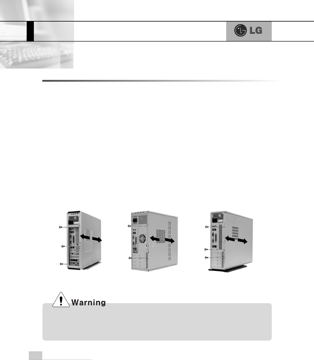
3-1. Opening the computer case
Always consult with your service representatives before opening the computer case.
Follow the guidelines below when opening the case.
Opening and closing the computer case
To open, remove the screws and pull the case cover toward the real of the computer.
To close, push the cover toward the front of the computer and tighten the screws.
Quit all running programs.
Turn off the computer and monitor, and unplug and remove the power cords.
Keep magnetic objects such as screw driver away from the parts inside the computer.
Open the computer case in a safe, clean area.
The static electricity can damage the parts inside the computer. Touch a bare,
unpainted metal part of the computer for 2~3 seconds to remove the static electricity
before opening the computer case.
FG CG/DG/CM EG
Make sure that there is no metallic object left inside the computer before closing
the case. There is the risk of electric shock or fire.
21System Expansion
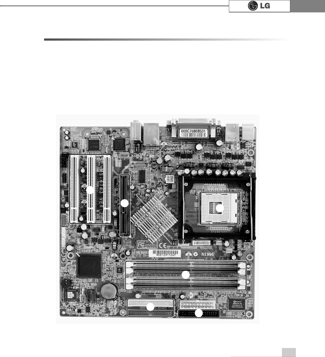
3-2. Main board
The main board determines the model name of your computer. Check the model
name on a label located at the real of your computer before system expansion.
Note: The main board in your computer may look different from the picture.
℘
3&,VORW
ℙ
$*3VORW
ℚ
&38VRFNHW
ℛ
0HPRU\VRFNHW',00
ℜ
)ORRS\GLVNFRQQHFWRU
ℝ
+DUGGLVN&'520FRQQHFWRU
ก
ข
ฃ
ฅค
22 System Expansion
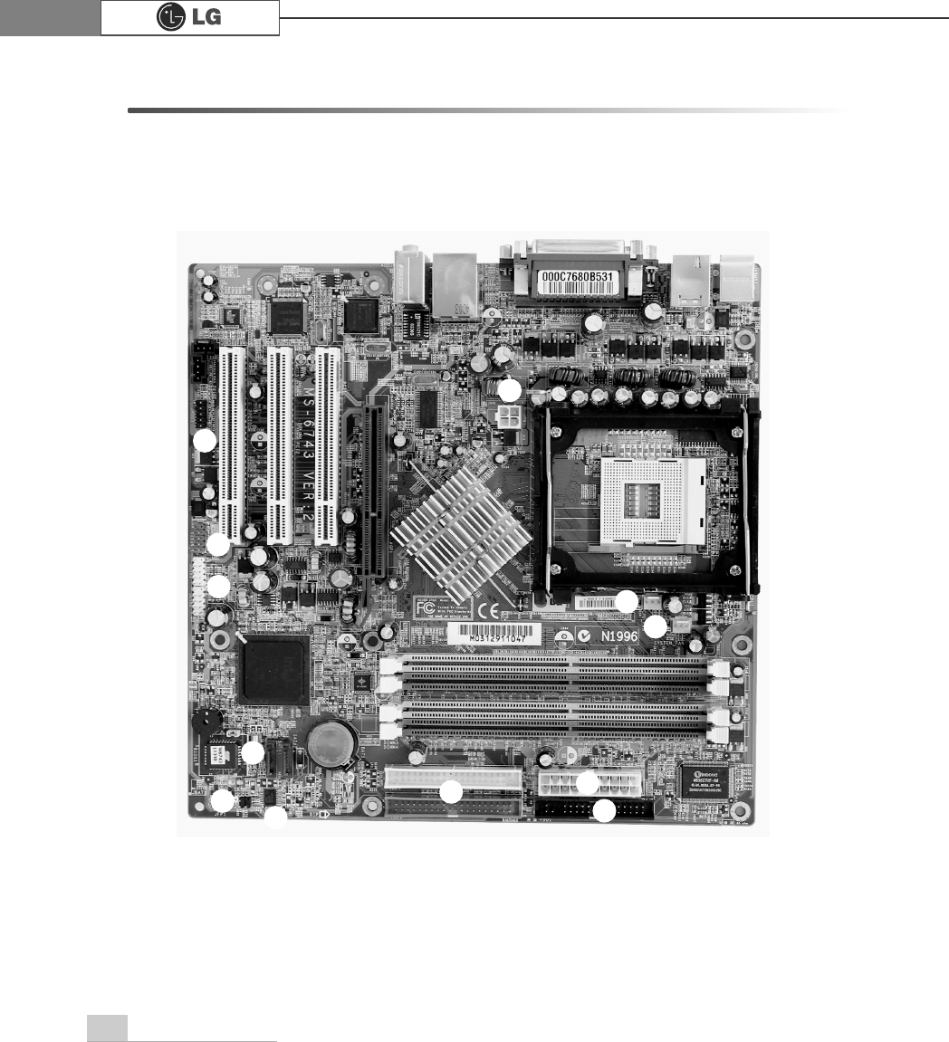
Note: You can distinguish the location of each cable by its color.
B: Black, R: Red, G1: Gray, W: White, G2: Green, Y: Yellow
3-3. Connectors
The peripheral devices are connected to the main board through the connectors shown
below. (The main board in your computer may look different from the picture below)
ก
ข
ค
ฃ
ฆ
ฉ
จ
ง
ฅ