LG Electronics USA DT-EH PERSONAL COMPUTER User Manual EHEM
LG Electronics USA PERSONAL COMPUTER EHEM
UserManual.wiki
>
LG Electronics USA
>
DT-EH User Manual
>
USERS MANUAL 4
Contents
1.
USERS MANUAL 1
2.
USERS MANUAL 2
3.
USERS MANUAL 3
4.
USERS MANUAL 4
USERS MANUAL 4
Navigation menu
Upload a User Manual
Namespaces
Wiki Guide
HTML
PDF
Info
Views
User Manual
Discussion / Help
Navigation
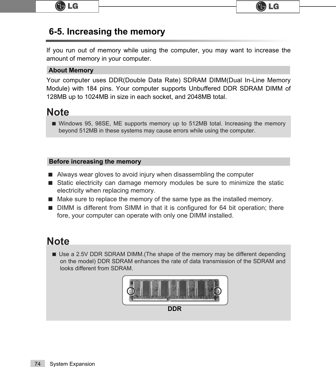
![75System ExpansionCheck the type of memory installed in your computer and refer to the memory config-uration chart before purchasing a memory.Specification: PC2100/2700/3200(184 pin DDR SDRAM DIMM)Speed : 266MHz(133MHz X 2), 333MHz(166MHz X 2), 400MHz(200 X 20)Size : 256MB, 512MBTotal memory DIMM 1 DIMM 2512MB256MB 256MB1024MB 512MB 512MB256MB 256MB (One of two slots)512MB (One of two slots)Purchasing a memoryMemory configuration chartãYour computer supports PC2100/2700/3200 DDR memory. ãUse Unbuffered DDR SDRAM DIMM only to increase the memory. FSB Frequency0+]Supported memory type3&''56'5$00+]](https://usermanual.wiki/LG-Electronics-USA/DT-EH.USERS-MANUAL-4/User-Guide-494448-Page-9.png)
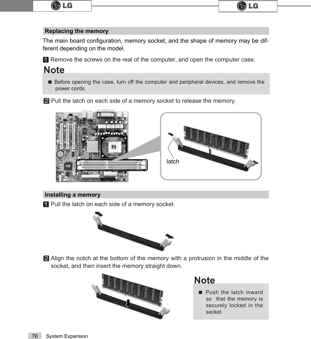
![77System ExpansionChecking the size of the installed memoryThe computer automatically recognizes the newly installed memory; therefore, you donot need to change the system setup. Follow the instruction below to check the sizeof the installed memory.ⓞConnect the power cord and other devices, and turn on the computer and monitor.ⓟIf the following screen appears, press [Esc]. POST screen appears.ⓠIf the following screen appears, press [Pause] key to pause the screen. Makesure [Memory Testing : XXXXXX OK] appears.ⓡPress [Esc] to continue the startup.Award Modular BIOS vX.XXXX, An Energy Star AllyCopyright(C) 1984-2004, Award Software, Inc.Build ID : LG XXXX XX.XX XX:XX:XX Main Processor : Intel(R) Pentium(R) X Processor XXXMHzMemory Test : XXXXXX OKPress DEL to enter SETUP XX/XX/XX-XXXX-XXXX-XXXXXXXXX-XXMemory Testing : XXXXXX OK ãTo stop the logo screen for amoment, press [Delete] key ⎀Advanced BIOS Features ⎀Full Screen Logo ShowSelectable, and then selectDisable.Note](https://usermanual.wiki/LG-Electronics-USA/DT-EH.USERS-MANUAL-4/User-Guide-494448-Page-11.png)
![78 System ExpansionⓞTurn on the computer and monitor.ⓟPress [Delete] key when the logo screen appears.ⓠThe CMOS Setup Utility opens.ⓡUse arrow [êê@>ëë@>éé@>èè@keys to select Standard CMOS Features, and press [Enter].Phoenix-Award BIOS CMOS Setup UtilityĚStandard CMOS Features ĚPC Health StatusĚAdvanced BIOS Features ĚFrequency/Voltage ControlĚAdvanced Chipset Features Load Optimized Defaults ĚIntegrated Peripherals Set PasswordĚPower Management Setup Save & Exit SetupĚPnP/PCI Configurations Exit Without SavingEsc : Quit êëè é : Select ltemF10 : Save & Exit SetupTime, Date, Hard Disk Type.....Hard disk drive setup](https://usermanual.wiki/LG-Electronics-USA/DT-EH.USERS-MANUAL-4/User-Guide-494448-Page-12.png)
![79System ExpansionⓢUse arrow [êê@>ëë@>éé@>èè@ keys to select IDE Primary Slave, and press[Enter].ⓣAfter setting IDE Primary Slave to Auto by pressing [Enter], press [Enter] inIDE HDD Auto-Detection so the system automatically recognizes the newlyinstalled slave hard disk drive.ⓤPress [F10] to save the new setting.ⓥIf the following message appears, press [Enter]. The computer restarts.Data (mm:dd:yy) XXX, XXX, XXXXTime (hh:mm:ss) XX, XX, XXĚIDE Primary Master [ST340015A]ĚIDE Primary Slave [None]ĚIDE Secondary Master [HL-DT-ST RW/DVDGCC-] ĚIDE Secondary Slave [None] Drive A [1.44M, 3.5 in.]Drive B [None]Floppy 3 Mode Support [Disabled]Video [EGA/VGA]Halt On [All, But Keyboard.]Base Memory 640 KExtended Memory 228352 KTotal Memory 229376 KItem HelpMenu Level ĚPress [Entre] to enternext page for detailthis drive settingsêëèé:Move Enter:Select +/-/PU/PD:Value F10:Save ESC:Exit F1:General HelpF5:Previous Values F7:Optimized Defaults>1RQH@Ě,'(3ULPDU\6ODYHIDE HDD Auto-DetectionPress EnterIDE Primary Slave AutoAccess Mode AutoCapacity 0 MB Cylinder 0Head 0Precomp 0Lauding Zome 0Sector 0 Item HelpMenu Level ĚTo auto-detect theHDD±s size, head...onthis channelêëèé:Move Enter:Select +/-/PU/PD:Value F10:Save ESC:Exit F1:General HelpF5:Previous Values F7:Optimized Defaults$XWR3UHVV(QWHUSAVE to CMOS and EXIT(Y/N)? Y Phoenix-Award BIOS CMOS Set up UtilityIDE Primary SlavePhoenix-Award BIOS CMOS Set up UtilityStandard CMOS Features](https://usermanual.wiki/LG-Electronics-USA/DT-EH.USERS-MANUAL-4/User-Guide-494448-Page-13.png)
![80 System ExpansionHard disk setup (Hard disk with factory default setting)ࣝ ಶಮऍ 1ڢܿીࡂ3٩މ+ⓞClick [Start] and [Run].ⓟType 'diskmgmt.msc' and press [OK].ⓠIf the following window appears, select disk1. Click right button on the mouse toselect New partition.ⓡClick [Next] if the following message appears.Be careful, Using <diskmgmt.msc> to divide partition delete data in a selected driver.](https://usermanual.wiki/LG-Electronics-USA/DT-EH.USERS-MANUAL-4/User-Guide-494448-Page-14.png)
![81System ExpansionⓢSelect a partition and click [Next].ⓣSelect the maximum size and click [Next].ⓤClick [Next] after selecting a drive value.A selected space of thedisk will be available touse.](https://usermanual.wiki/LG-Electronics-USA/DT-EH.USERS-MANUAL-4/User-Guide-494448-Page-15.png)
![82 System ExpansionⓥIf the following window appears, select File system, Allocation unit size andVolume label ,and click [Next].ⓦNew Partition Wizard is complete, click [Finish].ⓧAfter the format is complete, the hard disk operates normally.](https://usermanual.wiki/LG-Electronics-USA/DT-EH.USERS-MANUAL-4/User-Guide-494448-Page-16.png)