LG Electronics USA DT-EH PERSONAL COMPUTER User Manual EHEM
LG Electronics USA PERSONAL COMPUTER EHEM
Contents
- 1. USERS MANUAL 1
- 2. USERS MANUAL 2
- 3. USERS MANUAL 3
- 4. USERS MANUAL 4
USERS MANUAL 4
System Expansion 67
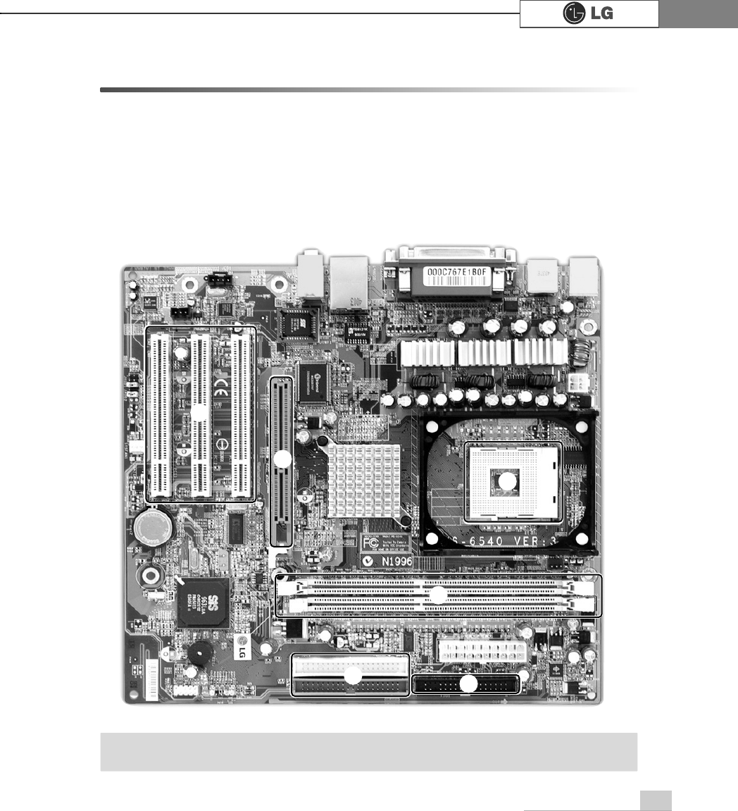
6-2. Main board
The main board determines the model name of your computer. Check the model
name on a label located at the real of your computer before system expansion.
℘PCI slot
ℙAGP slot
ℚCPU socket
ℛMemory socket (DIMM)
ℜFloppy disk connector
ℝHard disk/CD-ROM connector
ãThe main board in your computer may look different from the picture.
Note
ℙ
℘
ℚ
ℛ
ℝℜ
System Expansion68
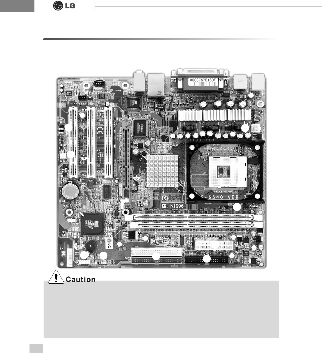
6-3. Connectors
The peripheral devices are connected to the main board through the connectors
shown below. (The main board in your computer may look different from the picture
below.)
℘
ℙ
ℚ
ℜ
ℛ
℠
℟
℞
ℝ
ãBefore removing the connector, check the status of connection and make a note.
ãAline the groove to the right direction when connecting floppy disk drive connector, hard
disk/CD-ROM connector.
ãMatch the pin number with the color of cable. There is a risk of disfunction to the computer.
ãRisk of explosin if battery is replaced by an incorrect type. dispose of used bayyeries
according to the instructions.
System Expansion 69
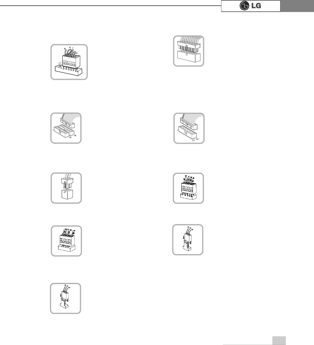
℘Power switch, power/ hard disk activity
LED connector (JFP1)
connects to the power
supply.
ℜPower connector(JPW1: 4 pins)
connects to the power.
ℙPower connector (CONN1: 20 pins)
connects to the USB on
the front of the comput-
er.
ℝUSB connector(JUSB1: 10 pins)
connects power
switch and hard disk
activity LED .
JFP1
ATX1
JPW1 JUSB 1
connects to the head-
phone and microphone
jacks on the front of the
computer.
℞Audio connector(JAUD1: 7 pins)
JAUD1
connects and supplies
power to the CPU fan.
℟CPU fan(C_FAN1: 3 pins)
CPU_FAN
IDE connector connects
hard disk and CD-ROM
drive. If only one hard disk
is connected, it should be
connected to IDEI1hard
disk connector.
connects to the floppy
disk drive.
ℚHard disk/CD-ROM drive connectors
(IDE1, IDE2: 40 pins)
ℛFloppy disk drive connector
(FDD1: 34 pins)
IDE1 IDE2 FDD1
connects and supplies
power to the system fan
at the bottom of the
computer.
℠System fan (S_FAN1: 3 pins)
SYSTEM_FAN
System Expansion70
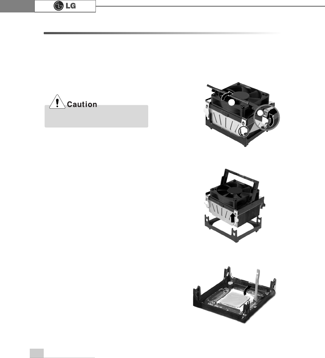
6-4 Replacing the CPU
The shape and replacement method of the CPU fan may be different depending
on the model.
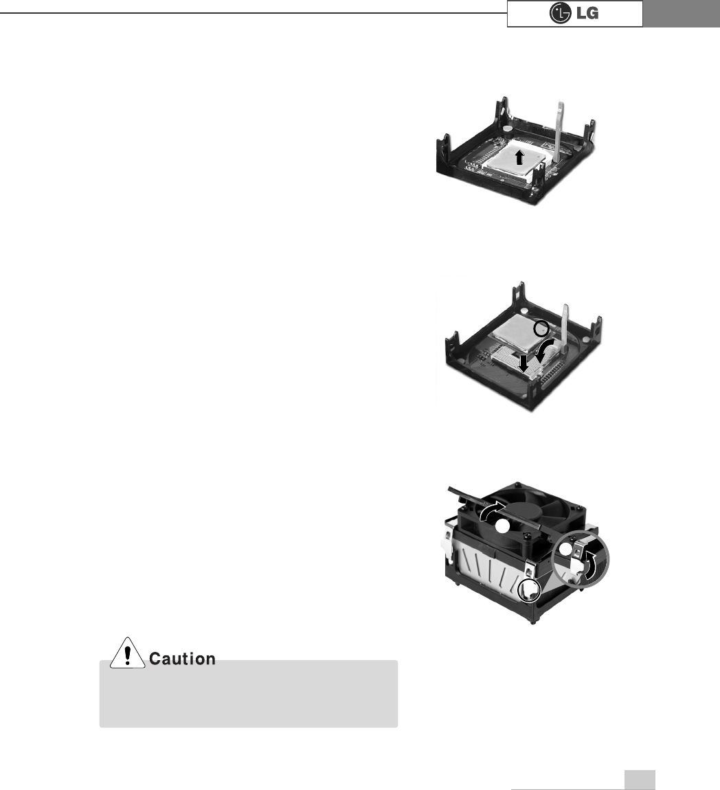
ⓞ
Clamps on both sides of the CPU fasten the fan tightly to the CPU socket.
raise the handle℘, release the clamps, and then spread them outwardℙ.
ⓟ
After releasing the clamps, lift and remove the CPU fan from the socket.
ⓠ
Raise the handle on the CPU socket to unlock the CPU.
℘
ℙ
Align the groove to the right position,
pins can easily be broken.
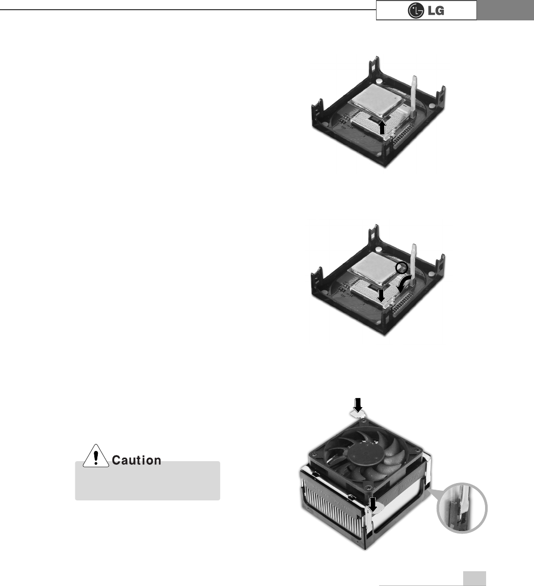
System Expansion 71
℘
ℙ
ⓢAlign the identifying marks at the corners of the new CPU and socket, and careful-
ly install the CPU in the socket. Lower the handle to lock the CPU in place.
ⓣower the handle as shown picture℘and lock the clamps as shown picture ℙ.
ⓡLift the CPU straight up. Be careful not to damage the pins at the bottom of the
CPU.
In a specific system, clamps are not fully open.
Raise the CPU fan from the fully opened space.
To assemble it, install from the opposite side.
72 System Expansion
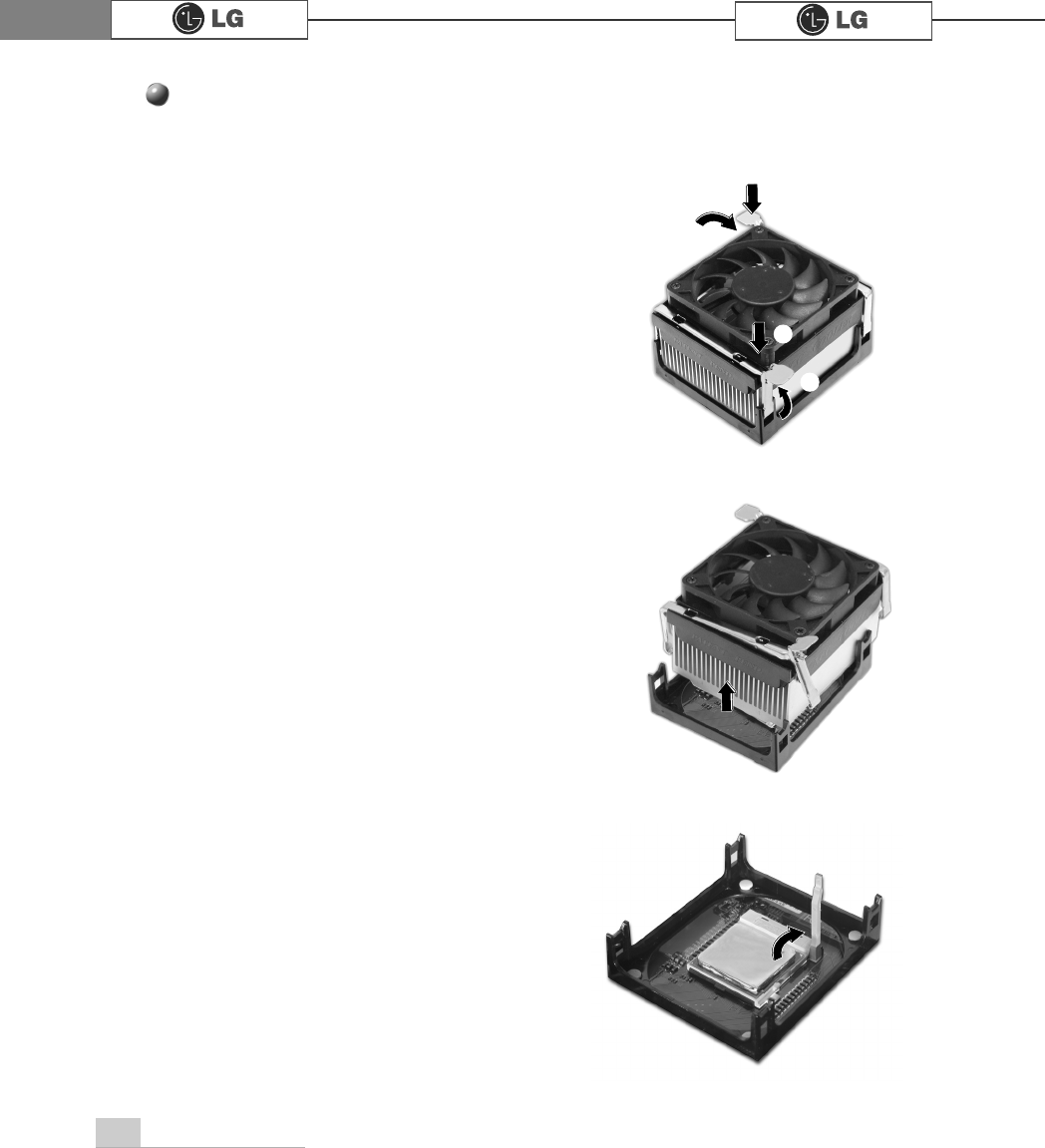
Replacing CPU
℘
℘
ℙ
ℙ
ⓞWhile pressing the both sides of the clamps as ℘, raise the fan to the direction
of ℙto release the clamps.
ⓟAfter releasing the clams, raise the CPU fan to remove.
ⓠRelease the CPU socket as the direction of arrow.
73System Expansion
ⓡRaise the CPU as the direction of arrrow.
ⓢGentely insert CPU in the right position and push the CPU socket to fasten.
ⓣPush the both side of clamps after align the grooves to the clamps.
Please gentely push the
clamps not to make it broken.

74 System Expansion
6-5. Increasing the memory
If you run out of memory while using the computer, you may want to increase the
amount of memory in your computer.
Your computer uses DDR(Double Data Rate) SDRAM DIMM(Dual In-Line Memory
Module) with 184 pins. Your computer supports Unbuffered DDR SDRAM DIMM of
128MB up to 1024MB in size in each socket, and 2048MB total.
ãAlways wear gloves to avoid injury when disassembling the computer
ãStatic electricity can damage memory modules be sure to minimize the static
electricity when replacing memory.
ãMake sure to replace the memory of the same type as the installed memory.
ãDIMM is different from SIMM in that it is configured for 64 bit operation; there
fore, your computer can operate with only one DIMM installed.
About Memory
Before increasing the memory
ãUse a 2.5V DDR SDRAM DIMM.(The shape of the memory may be different depending
on the model) DDR SDRAM enhances the rate of data transmission of the SDRAM and
looks different from SDRAM.
Note
DDR
ãWindows 95, 98SE, ME supports memory up to 512MB total. Increasing the memory
beyond 512MB in these systems may cause errors while using the computer.
Note
75System Expansion
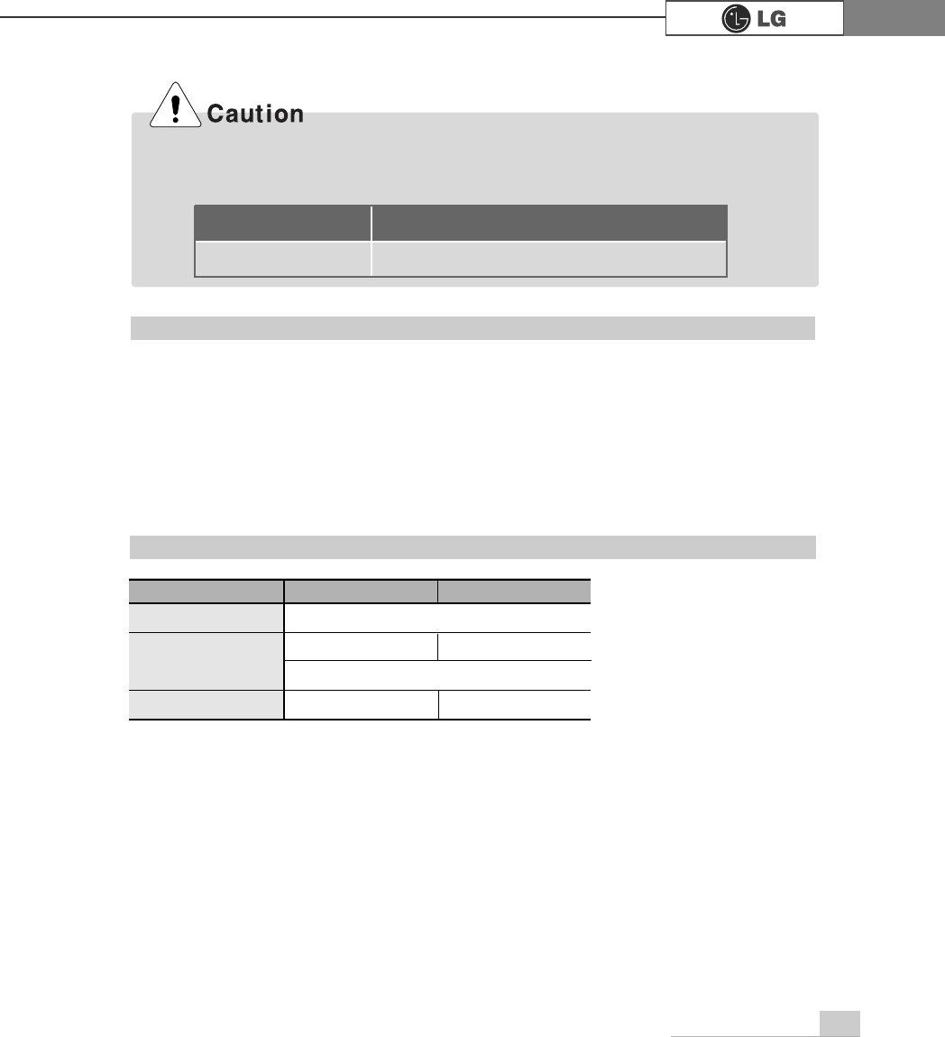
Check the type of memory installed in your computer and refer to the memory config-
uration chart before purchasing a memory.
Specification: PC2100/2700/3200(184 pin DDR SDRAM DIMM)
Speed : 266MHz(133MHz X 2), 333MHz(166MHz X 2), 400MHz(200 X 20)
Size : 256MB, 512MB
Total memory DIMM 1 DIMM 2
512MB
256MB 256MB
1024MB 512MB 512MB
256MB 256MB (One of two slots)
512MB (One of two slots)
Purchasing a memory
Memory configuration chart
ã
Your computer supports PC2100/2700/3200 DDR memory.
ã
Use Unbuffered DDR SDRAM DIMM only to increase the memory.
FSB Frequency
0+]
Supported memory type
3&''56'5$00+]
76 System Expansion
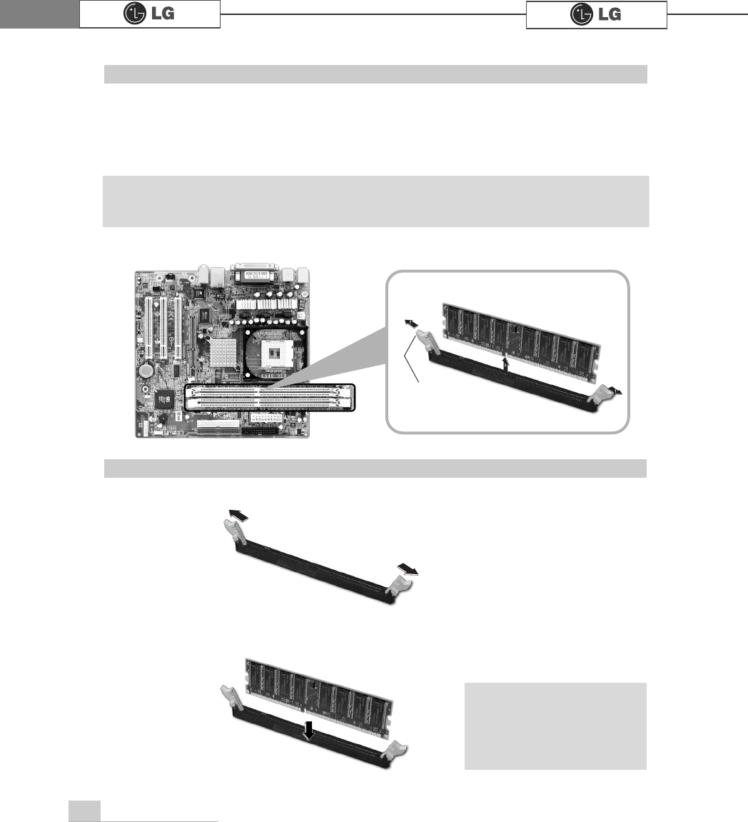
The main board configuration, memory socket, and the shape of memory may be dif-
ferent depending on the model.
ⓞRemove the screws on the real of the computer, and open the computer case.
ⓞPull the latch on each side of a memory socket.
ⓟPull the latch on each side of a memory socket to release the memory.
latch
Replacing the memory
ⓟAlign the notch at the bottom of the memory with a protrusion in the middle of the
socket, and then insert the memory straight down.
Installing a memory
ãPush the latch inward
so that the memory is
securely locked in the
socket.
Note
ãBefore opening the case, turn off the computer and peripheral devices, and remove the
power cords.
Note
77System Expansion
Checking the size of the installed memory
The computer automatically recognizes the newly installed memory; therefore, you do
not need to change the system setup. Follow the instruction below to check the size
of the installed memory.
ⓞConnect the power cord and other devices, and turn on the computer and monitor.
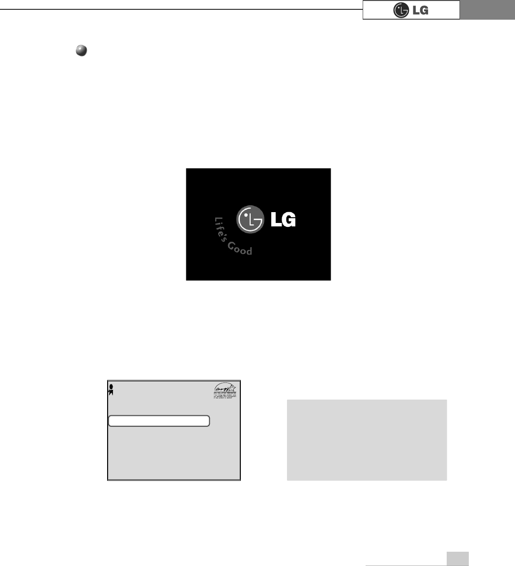
ⓟIf the following screen appears, press [Esc]. POST screen appears.
ⓠIf the following screen appears, press [Pause] key to pause the screen. Make
sure [Memory Testing : XXXXXX OK] appears.
ⓡPress [Esc] to continue the startup.
Award Modular BIOS vX.XXXX, An Energy Star Ally
Copyright(C) 1984-2004, Award Software, Inc.
Build ID : LG XXXX XX.XX XX:XX:XX
Main Processor : Intel(R) Pentium(R) X Processor XXXMHz
Memory Test : XXXXXX OK
Press DEL to enter SETUP
XX/XX/XX-XXXX-XXXX-XXXXXXXXX-XX
Memory Testing : XXXXXX OK ãTo stop the logo screen for a
moment, press [Delete] key ⎀
Advanced BIOS Features ⎀
Full Screen Logo Show
Selectable, and then select
Disable.
Note
78 System Expansion
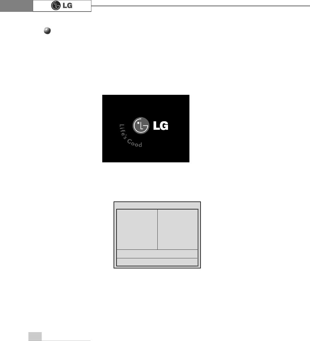
ⓞTurn on the computer and monitor.
ⓟPress [Delete] key when the logo screen appears.
ⓠThe CMOS Setup Utility opens.
ⓡ
Use arrow [êê@>ëë@>éé@>èè@keys to select Standard CMOS Features, and
press [Enter].
Phoenix-Award BIOS CMOS Setup Utility
ĚStandard CMOS Features Ě
PC Health Status
ĚAdvanced BIOS Features ĚFrequency/Voltage Control
ĚAdvanced Chipset Features Load Optimized Defaults
ĚIntegrated Peripherals Set Password
ĚPower Management Setup Save & Exit Setup
ĚPnP/PCI Configurations Exit Without Saving
Esc : Quit êëè é : Select ltem
F10 : Save & Exit Setup
Time, Date, Hard Disk Type.....
Hard disk drive setup
79System Expansion
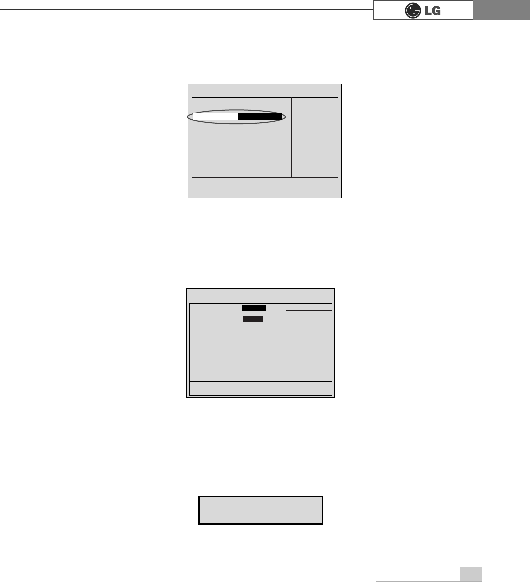
ⓢ
Use arrow [êê@>ëë@>éé@>èè@ keys to select IDE Primary Slave, and press
[Enter].
ⓣ
After setting IDE Primary Slave to Auto by pressing [Enter], press [Enter] in
IDE HDD Auto-Detection so the system automatically recognizes the newly
installed slave hard disk drive.
ⓤPress [F10] to save the new setting.
ⓥIf the following message appears, press [Enter]. The computer restarts.
Data (mm:dd:yy) XXX, XXX, XXXX
Time (hh:mm:ss) XX, XX, XX
ĚIDE Primary Master [ST340015A]
ĚIDE Primary Slave [None]
ĚIDE Secondary Master [HL-DT-ST RW/DVD
GCC-]
ĚIDE Secondary Slave [None]
Drive A [1.44M, 3.5 in.]
Drive B [None]
Floppy 3 Mode Support [Disabled]
Video [EGA/VGA]
Halt On [All, But Keyboard.]
Base Memory 640 K
Extended Memory 228352 K
Total Memory 229376 K
Item Help
Menu Level Ě
Press [Entre] to enter
next page for detail
this drive settings
êëèé:Move Enter:Select +/-/PU/PD:Value F10:Save ESC:Exit F1:General Help
F5:Previous Values F7:Optimized Defaults
>1RQH@
Ě
,'(3ULPDU\6ODYH
IDE HDD Auto-Detection
Press Enter
IDE Primary Slave Auto
Access Mode Auto
Capacity 0 MB
Cylinder 0
Head 0
Precomp 0
Lauding Zome 0
Sector 0
Item Help
Menu Level Ě
To auto-detect the
HDD±s size, head...on
this channel
êëèé:Move Enter:Select +/-/PU/PD:Value F10:Save ESC:Exit F1:General Help
F5:Previous Values F7:Optimized Defaults
$XWR
3UHVV(QWHU
SAVE to CMOS and EXIT(Y/N)? Y
Phoenix-Award BIOS CMOS Set up Utility
IDE Primary Slave
Phoenix-Award BIOS CMOS Set up Utility
Standard CMOS Features
80 System Expansion
Hard disk setup (Hard disk with factory default setting)
ࣝ ಶಮऍ 1
ڢܿીࡂ3
٩މ+
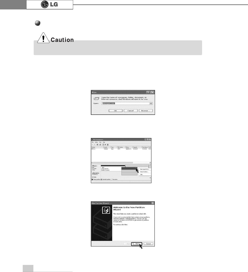
ⓞClick [Start] and [Run].
ⓟType 'diskmgmt.msc' and press [OK].
ⓠIf the following window appears, select disk1. Click right button on the mouse to
select New partition.
ⓡClick [Next] if the following message appears.
Be careful, Using <diskmgmt.msc> to divide partition delete data in a selected driver.
81System Expansion
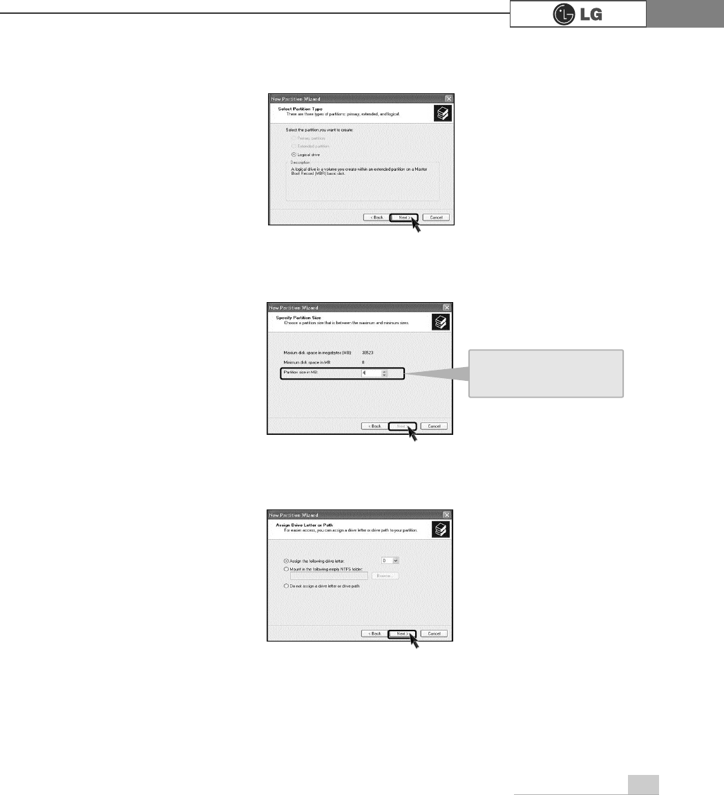
ⓢSelect a partition and click [Next].
ⓣSelect the maximum size and click [Next].
ⓤClick [Next] after selecting a drive value.
A selected space of the
disk will be available to
use.
82 System Expansion
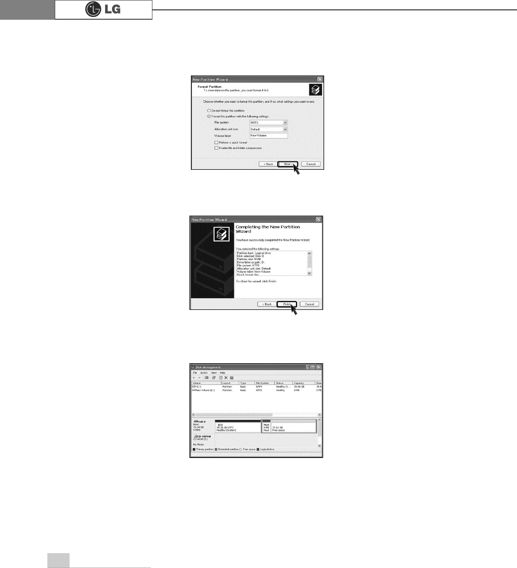
ⓥIf the following window appears, select File system, Allocation unit size and
Volume label ,and click [Next].
ⓦNew Partition Wizard is complete, click [Finish].
ⓧAfter the format is complete, the hard disk operates normally.
83System Expansion
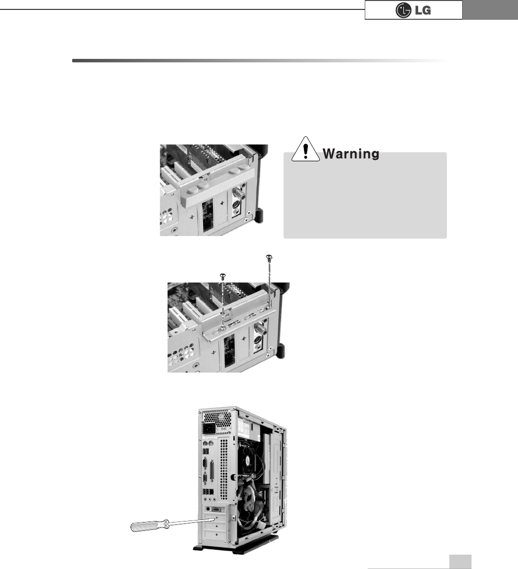
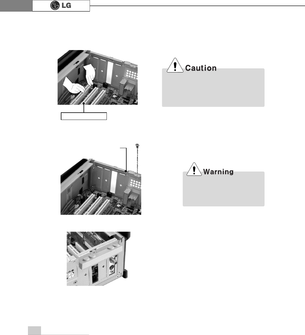
6-6.Installing expansion cards
When you are using the computer, you may need to install expansion cards to
improve funtionality. The following instruction describes how to install expansion
cards.
ⓞRefer to Opening the computer case to open the computer case cover.
ⓠRemove 2 screws as shown on the picture.
ⓡUse the driver and remove the metal slot cover.
(Remove it, only when installing an additional extension card.)
ãAlways use a screwdriver to open
the case cover. There is the risk of
injury.
ãIn order not to be injured when
disassembling the computer, wear
the gloves.
ⓟRemove the capas shown on the picture.
84 System Expansion
ⓥRefer to Closing the computer case to close the case cover of the computer.
ⓦInstall the driver program for the new expansion card.
ⓣFasten a screw after installing a metal bracket.
ⓢHold the expansion card with both hands and align the expansion card and slot.
Push down evenly to insert the card into the slot.
ãIncorrect installation of an expansion
card may damage the main board
and result in a computer malfunc
tion.
Using the computer without
closing the case may result in
fire, electric shock, injury, and/or
damage to the computer.
ⓤClose the cap in the same position as you removed it.
Expansion slot
metal bracket

85System Expansion
Specifications *
(+PRGHO
Floppy disk driver One 3.5inch 1.44MB drive
Keyboard PS/2 keyboard (104keys)
Mouse PS/2 mouse or USB (ball / wheel)
Video Integrated or external AGP graphic
Sound Built-in AC'97 audio. Support MIC-IN, SPEAKER-OUT and
LINE-IN.(Support virtual 5.1 channel output)
System memory
256MB (up to 2GB) - If built-in VGA is used, maximum 32MB
could be applied for the Video Frame Buffer and its size is con-
trolled by the system automatically.
CPU
Intel Pentium 4 / Celeron mPGA478 type (2.4GHz or above)
Cache memory L1: 16KB/36KB/or above, L2: 128KB/256KB/512KB/1024KB/or
above. Its size is different depending on the CPU.
Hard disk drive 40GB or above (E-IDE type)
LAN Integrated 10/100Base-T Ethernet
USB 6ports (support USB 2.0)
Serial I/O One RS-232C (9pins)
Parallel I/O One printer port (25pins)
Front I/O Two USB ports and audio ports (SPEAKER-OUT and MIC-IN)
Extension slot Three PCI slots, one AGP slot and two memory DIMM slots
Product size Width 136 x Height 354 x depth 378(mm)
Cable Power cable length 1.8m
Power spec Voltage: 100~127/200~240VAC
Frequency: 50/60 Hz

86 System Expansion
PHPR

memo 87
PHPR

memo88
PHPR